JP2009001138A - Instrument panel - Google Patents
Instrument panel Download PDFInfo
- Publication number
- JP2009001138A JP2009001138A JP2007163553A JP2007163553A JP2009001138A JP 2009001138 A JP2009001138 A JP 2009001138A JP 2007163553 A JP2007163553 A JP 2007163553A JP 2007163553 A JP2007163553 A JP 2007163553A JP 2009001138 A JP2009001138 A JP 2009001138A
- Authority
- JP
- Japan
- Prior art keywords
- tray
- instrument panel
- light source
- light
- panel
- Prior art date
- Legal status (The legal status is an assumption and is not a legal conclusion. Google has not performed a legal analysis and makes no representation as to the accuracy of the status listed.)
- Granted
Links
- 239000000463 material Substances 0.000 claims abstract description 10
- 230000005540 biological transmission Effects 0.000 description 8
- 210000000078 claw Anatomy 0.000 description 7
- 230000000694 effects Effects 0.000 description 4
- 238000004378 air conditioning Methods 0.000 description 3
- 230000007423 decrease Effects 0.000 description 3
- 230000002411 adverse Effects 0.000 description 2
- 238000004519 manufacturing process Methods 0.000 description 2
- 239000004743 Polypropylene Substances 0.000 description 1
- 230000003467 diminishing effect Effects 0.000 description 1
- 230000002093 peripheral effect Effects 0.000 description 1
- -1 polypropylene Polymers 0.000 description 1
- 229920001155 polypropylene Polymers 0.000 description 1
Images


Classifications
-
- B—PERFORMING OPERATIONS; TRANSPORTING
- B60—VEHICLES IN GENERAL
- B60Q—ARRANGEMENT OF SIGNALLING OR LIGHTING DEVICES, THE MOUNTING OR SUPPORTING THEREOF OR CIRCUITS THEREFOR, FOR VEHICLES IN GENERAL
- B60Q3/00—Arrangement of lighting devices for vehicle interiors; Lighting devices specially adapted for vehicle interiors
- B60Q3/10—Arrangement of lighting devices for vehicle interiors; Lighting devices specially adapted for vehicle interiors for dashboards
- B60Q3/12—Arrangement of lighting devices for vehicle interiors; Lighting devices specially adapted for vehicle interiors for dashboards lighting onto the surface to be illuminated
-
- B—PERFORMING OPERATIONS; TRANSPORTING
- B60—VEHICLES IN GENERAL
- B60Q—ARRANGEMENT OF SIGNALLING OR LIGHTING DEVICES, THE MOUNTING OR SUPPORTING THEREOF OR CIRCUITS THEREFOR, FOR VEHICLES IN GENERAL
- B60Q3/00—Arrangement of lighting devices for vehicle interiors; Lighting devices specially adapted for vehicle interiors
- B60Q3/20—Arrangement of lighting devices for vehicle interiors; Lighting devices specially adapted for vehicle interiors for lighting specific fittings of passenger or driving compartments; mounted on specific fittings of passenger or driving compartments
- B60Q3/225—Small compartments, e.g. glove compartments
Abstract
Description
本発明は、操作部に隣接した収納部を備えるインストルメントパネルに関し、更に詳しくは、特別に光源を設けることなく、前記収納部内を光で照らすことが可能なインストルメントパネルに関する。 The present invention relates to an instrument panel including a storage unit adjacent to an operation unit, and more particularly to an instrument panel that can illuminate the storage unit with light without providing a light source.
車両のインストルメントパネルには、車両の機器を制御可能にする各種操作部が設置され、多くの場合、乗員が操作部に設けられた操作パネルに触れて車両の機器を制御することとなる。このような操作部を有する機器としては、空調ユニット、オーディオ装置などが挙げられる。また、インストルメントパネルに、小物などを収納するための収納部が設置されているものがある。操作部および収納部にはそれぞれ光源が設けられており、夜間など暗がりで乗員が視認し易いように、それぞれの光源により操作パネルおよび収納部の内部を照らす機能を有している。 Various operation units that allow control of the vehicle equipment are installed on the instrument panel of the vehicle, and in many cases, a passenger touches the operation panel provided on the operation unit to control the vehicle equipment. Examples of the device having such an operation unit include an air conditioning unit and an audio device. Some instrument panels have storage units for storing small items. Each of the operation unit and the storage unit is provided with a light source, and has a function of illuminating the inside of the operation panel and the storage unit with each light source so that an occupant can easily see in the dark such as at night.
特に収納部に関しては、乗員が収納部の内部に入れた小物などを確実に確認できるように、収納部の内部を均一に光で照らすることが求められる。このような要求に対応したインストルメントパネルは特許文献1に開示されている。特許文献1のインストルメントパネルでは、収納部に開閉可能な蓋として構成されたパネル部が設けられ、パネル部の開閉に連動して移動する光源が設けられている。従って、パネル部の閉状態でパネル部自体が光源により照らされ、かつパネル部の開状態で収納部の内部が光源により照らされることとなる。
In particular, regarding the storage unit, it is required to uniformly illuminate the inside of the storage unit with light so that an occupant can surely check small items or the like put in the storage unit. An instrument panel corresponding to such a requirement is disclosed in
また、操作部および収納部を共に効率良く照明するために、同一の光源により操作部および収納部を照明することが行われており、このようなインストルメントパネルは特許文献2に開示されている。特許文献2のインストルメントパネルでは、オーディオ装置が装備され、このオーディオ装置のパネルがフィニッシャにより覆われており、このフィニッシャは、単一の光源より発せられた光を、オーディオの操作パネルの採光部を経由させ、収納部に配置された採光部まで伝達させるように構成されている。従って、操作パネルおよび収納部の両方が、それぞれの採光部から発せられる光により照らされることとなる。
Further, in order to efficiently illuminate both the operation unit and the storage unit, the operation unit and the storage unit are illuminated with the same light source, and such an instrument panel is disclosed in
しかしながら、特許文献1のインストルメントパネルでは、光源が収納部専用として設けられており、操作パネルを照明するためには、別途光源が必要である。そのため、部品点数が増加し、部品組立の工数が増加し、部品管理が難しくなり、これに伴いコストが増加することとなる。また、複数の光源を設けるためにはさらにスペースが必要となり、光源の配置スペースが増えることに伴って収納部の収納スペースが減少することとなる。
However, in the instrument panel of
また、特許文献2のインストルメントパネルでは、単一の光源を伝達するためのフィニッシャが複雑な形状となっている。そのため、フィニッシャの作製が難易化し、フィニッシャを作製するためのコストが増加することとなる。また、収納部の内部は採光部の光により照らされるが、採光部の周縁部分は採光部の光によって照らされ難く、収納部の内部が均一な明るさになり難くなっている。
Moreover, in the instrument panel of
そこで、本発明の課題は、特別な光源を設けることなく、収納部の内部を均一に明るくすることが可能なインストルメントパネルを提供することにある。 Then, the subject of this invention is providing the instrument panel which can make the inside of a storage part bright uniformly, without providing a special light source.
課題を解決するために本発明のインストルメントパネルは以下の特徴を有する。車両を制御するための操作パネルを有する操作部を備え、該操作部に前記操作パネルを光で照らすための光源を備え、前記操作部に隣接して配置された収納部を備えているインストルメントパネルにおいて、前記操作部と前記収納部との間に開口部を設け、該開口部と前記収納部との間に壁面としてトレーを設け、前記開口部を介して透過される前記光源の光を透過可能にする材料で前記トレーを形成している。 In order to solve the problems, the instrument panel of the present invention has the following features. An instrument comprising an operation unit having an operation panel for controlling a vehicle, a light source for illuminating the operation panel with light on the operation unit, and a storage unit disposed adjacent to the operation unit In the panel, an opening is provided between the operation unit and the storage unit, a tray is provided as a wall surface between the opening and the storage unit, and the light from the light source transmitted through the opening is transmitted. The tray is formed of a material that allows permeation.
また、本発明のインストルメントパネルでは、前記トレーの板厚が部分的に変化して形成されていてもよい。 In the instrument panel of the present invention, the tray thickness may be partially changed.
さらに、本発明のインストルメントパネルでは、前記収納部が車両後方側に開口端部を有する空間として形成され、前記光源および前記開口部が前記収納部の下方に配置され、前記トレーが前記空間の下側に配置され、前記開口端部の上側部分が前記トレーの形成する前記開口端部の下側部分より車両後方側に延出して形成されていてもよい。 Furthermore, in the instrument panel of the present invention, the storage portion is formed as a space having an opening end on the vehicle rear side, the light source and the opening are disposed below the storage portion, and the tray is disposed in the space. It is arranged on the lower side, and the upper part of the opening end part may be formed to extend to the vehicle rear side from the lower part of the opening end part formed by the tray.
さらに、本発明のインストルメントパネルでは、前記トレーが前記インストルメントパネルの本体と別部品として構成されていてもよい。 Furthermore, in the instrument panel of the present invention, the tray may be configured as a separate part from the main body of the instrument panel.
本発明によれば、以下の効果を得ることができる。本発明のインストルメントパネルは、車両を制御するための操作パネルを有する操作部を備え、該操作部に前記操作パネルを光で照らすための光源を備え、前記操作部に隣接して配置された収納部を備えているインストルメントパネルにおいて、前記操作部と前記収納部との間に開口部を設け、該開口部と前記収納部との間に壁面としてトレーを設け、前記開口部を介して透過される前記光源の光を透過可能にする材料で前記トレーを形成していることを特徴としている。そのため、複雑な構造の部品を用いずに、前記操作部および前記収納部の両方を同一の前記光源の光により照らすことが可能となる。その結果、部品の作製が容易になり、部品点数が減少し、部品組立の工数が減少し、部品管理が容易になり、これに伴いコストダウンが可能となる。 According to the present invention, the following effects can be obtained. The instrument panel of the present invention includes an operation unit having an operation panel for controlling a vehicle, and includes a light source for illuminating the operation panel with light in the operation unit, and is disposed adjacent to the operation unit. In an instrument panel including a storage portion, an opening is provided between the operation portion and the storage portion, a tray is provided as a wall surface between the opening and the storage portion, and the opening is provided via the opening. The tray is formed of a material that can transmit light from the light source that is transmitted. For this reason, it is possible to illuminate both the operation unit and the storage unit with the light of the same light source without using components having a complicated structure. As a result, parts can be easily manufactured, the number of parts is reduced, the number of parts assembly steps is reduced, parts management is facilitated, and costs can be reduced accordingly.
本発明のインストルメントパネルでは、前記トレーの板厚が部分的に変化して形成されていてもよく、板厚の変化に対応して前記光源の光の透過量を変化させることが可能となる。従って、必要に応じて前記収納部の部分ごとの明るさを調整することが可能である。 In the instrument panel of the present invention, the plate thickness of the tray may be partially changed, and the light transmission amount of the light source can be changed corresponding to the change of the plate thickness. . Therefore, it is possible to adjust the brightness of each portion of the storage portion as necessary.
本発明のインストルメントパネルでは、前記収納部が車両後方側に開口端部を有する空間として形成され、前記光源および前記開口部が前記収納部の下方に配置され、前記トレーが前記空間の下側に配置され、前記開口端部の上側部分が前記トレーの形成する前記開口端部の下側部分より車両後方側に延出して形成されていてもよく、前記収納部が前記操作部の上側に配置されることによって、下方から上方に向かう前記光源の光がインストルメントパネルの上側に配置されるフロントガラスに映し出される弊害を防止しながら、上述した効果を得ることが可能となる。 In the instrument panel of the present invention, the storage portion is formed as a space having an opening end on the vehicle rear side, the light source and the opening are disposed below the storage portion, and the tray is located below the space. The upper end portion of the opening end portion may be formed to extend to the vehicle rear side from the lower portion of the opening end portion formed by the tray, and the storage portion may be located above the operation portion. By disposing the light source, the above-described effects can be obtained while preventing the adverse effect of the light of the light source traveling from below to above being reflected on the windshield disposed above the instrument panel.
本発明のインストルメントパネルでは、前記トレーが前記インストルメントパネルの本体と別部品として構成されていてもよく、前記トレーを透過性の材料で作製し、かつインストルメントパネルの本体を別の材料で作製することが可能となる。 In the instrument panel of the present invention, the tray may be configured as a separate part from the instrument panel body, the tray is made of a permeable material, and the instrument panel body is made of another material. It can be produced.
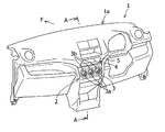
図1は、本発明の第一実施形態におけるインストルメントパネル1の全体を示しており、車両前側方向をFとする。本発明の第一実施形態では、図1より、インストルメントパネル1は本体1aを備え、インストルメントパネル1の車幅方向の中央部には、空調を制御するための空調ユニットの操作部2が設けられている。操作部2の車両後方側には、操作パネル3が配置されている。この操作パネル3は、一般にヒーターコントロールパネルと呼ばれるものであり、インストルメントパネル1の表面の一部として構成され、操作パネル3にはダイヤル3aなどの操作用部材が設けられている。ダイヤル3aの周囲を囲むように、光を透過可能な材料で作製された表示部3bが設けられている。
FIG. 1 shows the
また、インストルメントパネル1の操作部2の上側に隣接して、収納部4が設けられている。収納部4は略直方体の空間を有するように形成され、収納部4の車両後方側には開口端部5が設けられている。
A
図2は図1のA−A断面図であり、車両前側方向をFとする。図2より、操作部2の内部には光源6が配設されており、より具体的には、光源6は、操作パネル3から車両前後方向に間隔を空けて、かつ操作部2の上側部2a寄りの位置に配設されている。操作部2の上側部2aは光源6の上方に位置することとなり、上側部2aには開口部7が穿設されている。操作部2の上側部2aおよび開口部7の上方にはトレー8が配置されている。トレー8は、光を透過可能な半透明のポリプロピレン材により作製され、収納部4の下側壁面として、収納部4と一体になって構成されている。
2 is a cross-sectional view taken along the line AA in FIG. As shown in FIG. 2, a
このような構成により、光源6の光が、表示部3bを透過して操作パネル3を照らし、かつ開口部7を介してトレー8を透過して収納部4を照らすことが可能となる。従って、複雑な構造の部品を用いずに、操作パネル3および収納部4の両方を同一の光源6の光により照らすことが可能となる。その結果、部品の作製が容易になり、部品点数が減少し、部品組立の工数が減少し、部品管理が容易になり、これに伴いコストダウンが可能となる。
With this configuration, the light from the
また、トレー8の車両前後方向の後端部は、開口端部5の下側部分5aとして構成され、収納部4を構成する上側壁面4aの車両前後方向の後端部は、開口端部5の上側部分5bとして構成されており、上側部分5bは下側部分5aより車両後方側に延出して形成されている。
The rear end portion of the
従って、下方から上方に向かう光源6の光がインストルメントパネル1の上側に配置されるフロントガラス(図示せず)に映し出される弊害を防止することが可能となる。
Therefore, it is possible to prevent the adverse effect that the light of the
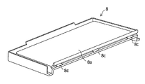
さらに図3より、トレー8は照明中心部8aを備え、照明中心部8aは、開口部7の上方に位置し、詳細にはトレー8の車幅方向中央でかつ車両後方側に寄って位置している。トレー8の板厚は照明中心部8aから平面方向に離れるに連れて薄くなるように形成されており、トレー8の平面全体を考慮して説明すると、トレー8は照明中心部8aから離れるに連れて平面方向に広がる放射状に薄くなって変化している。
Further, as shown in FIG. 3, the
そのため、トレー8の板厚の薄い部分では光源6の光の透過量が多く明るさが強くなり、トレー8の板厚の厚い部分では光源6の光の透過量が少なく明るさが弱まることとなる。一方で、開口部7から離れた箇所では光源6の光の強さは弱まっており、開口部7近傍の箇所では光源6の光の強さが強くなっている。従って、弱い光源6の光がトレー8の板厚の薄い部分を通過することにより、弱い光源6の光の透過量は減少せず、強い光源6の光がトレー8の板厚の厚い部分を通過することにより、強い光源6の光の透過量が減少して、収納部4に透過される光源6の光の透過量が均一に調節されることとなる。よって、収納部4を均一な明るさとすることが可能となる。
Therefore, the light transmission amount of the
次に、本発明の第二実施形態について説明する。図4は、本発明の第二実施形態における図2の収納部4を拡大した図であり、図5はトレー8全体の概略を示している。図4および図5より、トレー8の車両前後方向の前端部には前側爪部8bが設けられ、トレー8の車両前後方向の後端部には後側爪部8cが設けられている。図4より、収納部4を構成する車両前後方向の前側壁面4bの下端部にはトレー前側取付部4cが設けられ、トレー前側取付部4cはトレー8の前側爪部8bと嵌合可能に形成されている。さらに、操作パネル3の上端部にはトレー後側取付部3cが設けられ、トレー後側取付部3cはトレー8の後側爪部8cと嵌合可能に形成されている。このような構成により、前側爪部8bとトレー前側取付部4cとが嵌合し、後側爪部8cとトレー後側取付部3cとが嵌合して、トレー8がインストルメントパネル1の本体1aに取付けられることとなる。トレー8の板厚は照明中心部8aから離れるに連れて平面方向に広がる放射状に薄くなるように変化している。
Next, a second embodiment of the present invention will be described. FIG. 4 is an enlarged view of the
従って、トレー8とインストルメントパネル1の本体1aとが別部品で構成されることとなり、トレー8を透過性の材料で作製し、かつインストルメントパネルの本体1aを別の材料で作製することが可能となる。
Therefore, the
なお、第二実施形態は、トレー8とインストルメントパネル1の本体1aとが別部品として構成されている以外、第一実施形態と同様の形態である。
In addition, 2nd embodiment is a form similar to 1st embodiment except the
本発明の別の実施形態では、収納部4を操作部2の下側、車幅方向の左側または右側のいずれかに隣接して配置する構成としてもよく、インストルメントパネル1のデザインに合わせて配置位置を変更することにより、設計の自由度を高めることが可能となる。
In another embodiment of the present invention, the
本発明の別の実施形態では、収納部4の形状を略直方体以外にしてもよく、インストルメントパネル1のデザインに合わせて収納部4の形状を変更することにより、設計の自由度を高めることが可能となる。
In another embodiment of the present invention, the shape of the
本発明の別の実施形態では、トレー8の板厚の変化を収納部4の使用形態に合わせて適宜変更してもよく、収納部4の形状および配置位置の変化によって、収納部4の部分ごとで明るさが変化した場合に、光源6の光の透過量を調節することにより収納部4の内部の明るさを均一にすることが可能である。また、照明デザインなどの要求に応じて光源6の光の透過量を調節することも可能である。
In another embodiment of the present invention, the change in the thickness of the
1 インストルメントパネル
1a 本体
2 操作部
2a 上側部
3 操作パネル
3a ダイヤル
3b 表示部
3c トレー後側取付部
4 収納部
4a 上側壁面
4b 前側壁面
4c トレー前側取付部
5 開口端部
5a 下側部分
5b 上側部分
6 光源
7 開口部
8 トレー
8a 照明中心部
8b 前側爪部
8c 後側爪部
F 車両前側方向
DESCRIPTION OF
Claims (4)
前記操作部と前記収納部との間に開口部を設け、該開口部と前記収納部との間に壁面としてトレーを設け、前記開口部を介して透過される前記光源の光を透過可能にする材料で前記トレーを形成していることを特徴とするインストルメントパネル。 An instrument comprising an operation unit having an operation panel for controlling a vehicle, a light source for illuminating the operation panel with light on the operation unit, and a storage unit disposed adjacent to the operation unit In the panel,
An opening is provided between the operation unit and the storage unit, and a tray is provided as a wall surface between the opening and the storage unit so that light from the light source transmitted through the opening can be transmitted. An instrument panel, wherein the tray is formed of a material to be used.
Priority Applications (4)
| Application Number | Priority Date | Filing Date | Title |
|---|---|---|---|
| JP2007163553A JP4962858B2 (en) | 2007-06-21 | 2007-06-21 | instrument panel |
| DE102008001462A DE102008001462B4 (en) | 2007-06-21 | 2008-04-29 | dashboard |
| US12/139,019 US20090146446A1 (en) | 2007-06-21 | 2008-06-13 | Instrument Panel |
| US12/139,052 US7597377B2 (en) | 2007-06-21 | 2008-06-13 | Instrument panel |
Applications Claiming Priority (1)
| Application Number | Priority Date | Filing Date | Title |
|---|---|---|---|
| JP2007163553A JP4962858B2 (en) | 2007-06-21 | 2007-06-21 | instrument panel |
Publications (2)
| Publication Number | Publication Date |
|---|---|
| JP2009001138A true JP2009001138A (en) | 2009-01-08 |
| JP4962858B2 JP4962858B2 (en) | 2012-06-27 |
Family
ID=40030911
Family Applications (1)
| Application Number | Title | Priority Date | Filing Date |
|---|---|---|---|
| JP2007163553A Expired - Fee Related JP4962858B2 (en) | 2007-06-21 | 2007-06-21 | instrument panel |
Country Status (3)
| Country | Link |
|---|---|
| US (2) | US7597377B2 (en) |
| JP (1) | JP4962858B2 (en) |
| DE (1) | DE102008001462B4 (en) |
Cited By (2)
| Publication number | Priority date | Publication date | Assignee | Title |
|---|---|---|---|---|
| KR100978412B1 (en) * | 2009-01-30 | 2010-08-26 | 지엠대우오토앤테크놀로지주식회사 | Lighting Structure for Pocket Box in Vehicle |
| JP2015085793A (en) * | 2013-10-30 | 2015-05-07 | ダイハツ工業株式会社 | Housing part structure |
Families Citing this family (6)
| Publication number | Priority date | Publication date | Assignee | Title |
|---|---|---|---|---|
| EP1532974B1 (en) * | 2002-03-12 | 2008-12-17 | Galderma Research & Development | Composition comprising 6-[3-(1-adamantyl)-4-methoxyphenyl]-2-naphthoic acid for the treatment of dermatological disorders |
| DE102009001412B4 (en) * | 2009-03-09 | 2018-10-11 | Volkswagen Ag | Capacitive display and control element |
| US8474214B2 (en) * | 2011-01-26 | 2013-07-02 | Nissan North America, Inc. | Connecting structure for automotive trim panels |
| US8419103B2 (en) * | 2011-01-27 | 2013-04-16 | Nissan North America, Inc. | Panel assembly for a motor vehicle |
| USD837118S1 (en) * | 2016-11-14 | 2019-01-01 | Honda Motor Co., Ltd. | Instrument panel |
| JP6824308B2 (en) * | 2019-02-21 | 2021-02-03 | 本田技研工業株式会社 | Instrument panel member mounting structure |
Citations (5)
| Publication number | Priority date | Publication date | Assignee | Title |
|---|---|---|---|---|
| JPS5648600Y2 (en) * | 1977-10-07 | 1981-11-13 | ||
| JPS58116435U (en) * | 1982-02-04 | 1983-08-09 | 三菱自動車工業株式会社 | Globebox lighting system |
| JPS60163140U (en) * | 1984-04-10 | 1985-10-30 | 日産自動車株式会社 | finisher |
| JPS62203744U (en) * | 1986-06-17 | 1987-12-25 | ||
| JPH0876123A (en) * | 1994-09-02 | 1996-03-22 | Casio Comput Co Ltd | Illumination device |
Family Cites Families (18)
| Publication number | Priority date | Publication date | Assignee | Title |
|---|---|---|---|---|
| JPS6422758A (en) * | 1987-07-16 | 1989-01-25 | Meinan Machinery Works | Distributed transport device for board |
| US5273597A (en) * | 1988-11-26 | 1993-12-28 | Honda Giken Kogyo Kabushiki Kaisha | Trim member for motor vehicle and method of and system for manufacturing the same |
| SE466628B (en) * | 1988-12-30 | 1992-03-09 | Saab Scania Ab | COMMUNICATION UNIT FOR MOUNTING IN A VEHICLE |
| US5364159A (en) * | 1993-06-15 | 1994-11-15 | Davidson Textron Inc. | Structural instrument panel carrier assembly |
| US5775796A (en) * | 1996-04-12 | 1998-07-07 | Freightliner Corporation | Truck with overhead storage compartment lighting system |
| FR2763301B1 (en) * | 1997-05-14 | 1999-07-16 | Reydel Sa | DASHBOARD FOR VEHICLE, ESPECIALLY MOTOR VEHICLE |
| JP2002500131A (en) * | 1998-01-02 | 2002-01-08 | プリンス テクノロジー コーポレイション | Integrated modular instrument panel assembly |
| JP3867833B2 (en) * | 2000-03-23 | 2007-01-17 | 本田技研工業株式会社 | Vehicle display device |
| JP2001328460A (en) * | 2000-05-23 | 2001-11-27 | Denso Corp | Cockpit module assembly for vehicle and its assembling method |
| US6428072B1 (en) * | 2000-09-08 | 2002-08-06 | Auto Additions, Inc. | Vehicle equipment console |
| US6371551B1 (en) * | 2000-10-24 | 2002-04-16 | Ford Global Technologies, Inc. | Integrated steering column, instrument panel, and cowl body structure |
| DE60320332T2 (en) * | 2002-02-21 | 2009-07-09 | Calsonic Kansei Corp. | Dashboard for motor vehicle |
| US7036865B2 (en) * | 2004-04-08 | 2006-05-02 | Honda Motor Co., Ltd. | Automobile instrument panel structure |
| JP4243212B2 (en) * | 2004-04-12 | 2009-03-25 | 矢崎総業株式会社 | Storage box and instrument panel in which it is embedded |
| US7201420B2 (en) * | 2004-11-23 | 2007-04-10 | General Motors Corporation | Vehicle display screen |
| US7425891B2 (en) * | 2006-05-09 | 2008-09-16 | Lockheed Martin Corporation | Tactical truck system dashboard |
| US7507008B2 (en) * | 2007-01-29 | 2009-03-24 | Chrysler Llc | Accessory light |
| JP2009018612A (en) * | 2007-07-10 | 2009-01-29 | Toyoda Gosei Co Ltd | Vehicular center cluster panel |
-
2007
- 2007-06-21 JP JP2007163553A patent/JP4962858B2/en not_active Expired - Fee Related
-
2008
- 2008-04-29 DE DE102008001462A patent/DE102008001462B4/en not_active Expired - Fee Related
- 2008-06-13 US US12/139,052 patent/US7597377B2/en not_active Expired - Fee Related
- 2008-06-13 US US12/139,019 patent/US20090146446A1/en not_active Abandoned
Patent Citations (5)
| Publication number | Priority date | Publication date | Assignee | Title |
|---|---|---|---|---|
| JPS5648600Y2 (en) * | 1977-10-07 | 1981-11-13 | ||
| JPS58116435U (en) * | 1982-02-04 | 1983-08-09 | 三菱自動車工業株式会社 | Globebox lighting system |
| JPS60163140U (en) * | 1984-04-10 | 1985-10-30 | 日産自動車株式会社 | finisher |
| JPS62203744U (en) * | 1986-06-17 | 1987-12-25 | ||
| JPH0876123A (en) * | 1994-09-02 | 1996-03-22 | Casio Comput Co Ltd | Illumination device |
Cited By (2)
| Publication number | Priority date | Publication date | Assignee | Title |
|---|---|---|---|---|
| KR100978412B1 (en) * | 2009-01-30 | 2010-08-26 | 지엠대우오토앤테크놀로지주식회사 | Lighting Structure for Pocket Box in Vehicle |
| JP2015085793A (en) * | 2013-10-30 | 2015-05-07 | ダイハツ工業株式会社 | Housing part structure |
Also Published As
| Publication number | Publication date |
|---|---|
| US7597377B2 (en) | 2009-10-06 |
| US20090146446A1 (en) | 2009-06-11 |
| DE102008001462B4 (en) | 2012-12-27 |
| US20080315610A1 (en) | 2008-12-25 |
| JP4962858B2 (en) | 2012-06-27 |
| DE102008001462A1 (en) | 2008-12-24 |
Similar Documents
| Publication | Publication Date | Title |
|---|---|---|
| JP4962858B2 (en) | instrument panel | |
| JP4631838B2 (en) | Vehicle lighting | |
| US20100080010A1 (en) | Vehicle interior lighting device | |
| US20120002442A1 (en) | Display device for a vehicle and method for producing the display device | |
| JP2007196919A (en) | Lighting device for vehicle | |
| US8562058B1 (en) | Light module for upper and lower glove box bin | |
| JP2012148668A (en) | Defroster blowout port | |
| JP5227607B2 (en) | Vehicle storage box | |
| JP4656043B2 (en) | Door pocket lighting structure | |
| JP2009078794A (en) | Vehicle interior lighting system | |
| JP6246899B2 (en) | Decorative lighting structure | |
| JP2009096388A (en) | Vehicular cabin luminaire and its structure | |
| JP2016043729A (en) | Illumination device and illumination device for vehicle cabin | |
| JP2017010891A (en) | Vehicular lighting fixture | |
| JP5775405B2 (en) | Vehicle meter | |
| JP7333021B2 (en) | Vehicle storage box lighting structure | |
| JP2016047693A (en) | Illumination device for vehicle cabin | |
| JP2006196270A (en) | Push switch outer housing structure | |
| JP3595460B2 (en) | Cluster substructure | |
| JP5703708B2 (en) | Speaker grille assembly and speaker device including the same | |
| JP4853438B2 (en) | Vehicle interior lighting device | |
| JP2006321437A (en) | Canopy structure for vehicle | |
| JP2008087597A (en) | Structure of housing part inside cabin | |
| JP6167977B2 (en) | Lighting device | |
| JP2016112907A (en) | Vehicle cargo chamber lighting device |
Legal Events
| Date | Code | Title | Description |
|---|---|---|---|
| A621 | Written request for application examination |
Free format text: JAPANESE INTERMEDIATE CODE: A621 Effective date: 20100325 |
|
| A977 | Report on retrieval |
Free format text: JAPANESE INTERMEDIATE CODE: A971007 Effective date: 20110928 |
|
| A131 | Notification of reasons for refusal |
Free format text: JAPANESE INTERMEDIATE CODE: A131 Effective date: 20111104 |
|
| A521 | Request for written amendment filed |
Free format text: JAPANESE INTERMEDIATE CODE: A523 Effective date: 20111221 |
|
| A131 | Notification of reasons for refusal |
Free format text: JAPANESE INTERMEDIATE CODE: A131 Effective date: 20120117 |
|
| A521 | Request for written amendment filed |
Free format text: JAPANESE INTERMEDIATE CODE: A523 Effective date: 20120216 |
|
| TRDD | Decision of grant or rejection written | ||
| A01 | Written decision to grant a patent or to grant a registration (utility model) |
Free format text: JAPANESE INTERMEDIATE CODE: A01 Effective date: 20120302 |
|
| A01 | Written decision to grant a patent or to grant a registration (utility model) |
Free format text: JAPANESE INTERMEDIATE CODE: A01 |
|
| A61 | First payment of annual fees (during grant procedure) |
Free format text: JAPANESE INTERMEDIATE CODE: A61 Effective date: 20120315 |
|
| FPAY | Renewal fee payment (event date is renewal date of database) |
Free format text: PAYMENT UNTIL: 20150406 Year of fee payment: 3 |
|
| LAPS | Cancellation because of no payment of annual fees |