JP2009001073A - Pneumatic radial tire - Google Patents
Pneumatic radial tire Download PDFInfo
- Publication number
- JP2009001073A JP2009001073A JP2007161696A JP2007161696A JP2009001073A JP 2009001073 A JP2009001073 A JP 2009001073A JP 2007161696 A JP2007161696 A JP 2007161696A JP 2007161696 A JP2007161696 A JP 2007161696A JP 2009001073 A JP2009001073 A JP 2009001073A
- Authority
- JP
- Japan
- Prior art keywords
- tire
- layer
- pneumatic radial
- bead
- rubber
- Prior art date
- Legal status (The legal status is an assumption and is not a legal conclusion. Google has not performed a legal analysis and makes no representation as to the accuracy of the status listed.)
- Withdrawn
Links
Images

Classifications
-
- B—PERFORMING OPERATIONS; TRANSPORTING
- B60—VEHICLES IN GENERAL
- B60C—VEHICLE TYRES; TYRE INFLATION; TYRE CHANGING; CONNECTING VALVES TO INFLATABLE ELASTIC BODIES IN GENERAL; DEVICES OR ARRANGEMENTS RELATED TO TYRES
- B60C9/00—Reinforcements or ply arrangement of pneumatic tyres
- B60C9/02—Carcasses
- B60C9/14—Carcasses built-up with sheets, webs, or films of homogeneous material, e.g. synthetics, sheet metal, rubber
-
- B—PERFORMING OPERATIONS; TRANSPORTING
- B60—VEHICLES IN GENERAL
- B60C—VEHICLE TYRES; TYRE INFLATION; TYRE CHANGING; CONNECTING VALVES TO INFLATABLE ELASTIC BODIES IN GENERAL; DEVICES OR ARRANGEMENTS RELATED TO TYRES
- B60C15/00—Tyre beads, e.g. ply turn-up or overlap
- B60C15/0009—Tyre beads, e.g. ply turn-up or overlap features of the carcass terminal portion
- B60C15/0036—Tyre beads, e.g. ply turn-up or overlap features of the carcass terminal portion with high ply turn-up, i.e. folded around the bead core and terminating radially above the point of maximum section width
- B60C15/0045—Tyre beads, e.g. ply turn-up or overlap features of the carcass terminal portion with high ply turn-up, i.e. folded around the bead core and terminating radially above the point of maximum section width with ply turn-up up to the belt edges, i.e. folded around the bead core and extending to the belt edges
-
- B—PERFORMING OPERATIONS; TRANSPORTING
- B60—VEHICLES IN GENERAL
- B60C—VEHICLE TYRES; TYRE INFLATION; TYRE CHANGING; CONNECTING VALVES TO INFLATABLE ELASTIC BODIES IN GENERAL; DEVICES OR ARRANGEMENTS RELATED TO TYRES
- B60C9/00—Reinforcements or ply arrangement of pneumatic tyres
- B60C9/02—Carcasses
- B60C9/04—Carcasses the reinforcing cords of each carcass ply arranged in a substantially parallel relationship
- B60C9/08—Carcasses the reinforcing cords of each carcass ply arranged in a substantially parallel relationship the cords extend transversely from bead to bead, i.e. radial ply
-
- B—PERFORMING OPERATIONS; TRANSPORTING
- B60—VEHICLES IN GENERAL
- B60C—VEHICLE TYRES; TYRE INFLATION; TYRE CHANGING; CONNECTING VALVES TO INFLATABLE ELASTIC BODIES IN GENERAL; DEVICES OR ARRANGEMENTS RELATED TO TYRES
- B60C15/00—Tyre beads, e.g. ply turn-up or overlap
- B60C15/0009—Tyre beads, e.g. ply turn-up or overlap features of the carcass terminal portion
- B60C2015/009—Height of the carcass terminal portion defined in terms of a numerical value or ratio in proportion to section height
-
- Y—GENERAL TAGGING OF NEW TECHNOLOGICAL DEVELOPMENTS; GENERAL TAGGING OF CROSS-SECTIONAL TECHNOLOGIES SPANNING OVER SEVERAL SECTIONS OF THE IPC; TECHNICAL SUBJECTS COVERED BY FORMER USPC CROSS-REFERENCE ART COLLECTIONS [XRACs] AND DIGESTS
- Y10—TECHNICAL SUBJECTS COVERED BY FORMER USPC
- Y10T—TECHNICAL SUBJECTS COVERED BY FORMER US CLASSIFICATION
- Y10T152/00—Resilient tires and wheels
- Y10T152/10—Tires, resilient
- Y10T152/10495—Pneumatic tire or inner tube
- Y10T152/10819—Characterized by the structure of the bead portion of the tire
- Y10T152/10828—Chafer or sealing strips
-
- Y—GENERAL TAGGING OF NEW TECHNOLOGICAL DEVELOPMENTS; GENERAL TAGGING OF CROSS-SECTIONAL TECHNOLOGIES SPANNING OVER SEVERAL SECTIONS OF THE IPC; TECHNICAL SUBJECTS COVERED BY FORMER USPC CROSS-REFERENCE ART COLLECTIONS [XRACs] AND DIGESTS
- Y10—TECHNICAL SUBJECTS COVERED BY FORMER USPC
- Y10T—TECHNICAL SUBJECTS COVERED BY FORMER US CLASSIFICATION
- Y10T152/00—Resilient tires and wheels
- Y10T152/10—Tires, resilient
- Y10T152/10495—Pneumatic tire or inner tube
- Y10T152/10819—Characterized by the structure of the bead portion of the tire
- Y10T152/10837—Bead characterized by the radial extent of apex, flipper or chafer into tire sidewall
-
- Y—GENERAL TAGGING OF NEW TECHNOLOGICAL DEVELOPMENTS; GENERAL TAGGING OF CROSS-SECTIONAL TECHNOLOGIES SPANNING OVER SEVERAL SECTIONS OF THE IPC; TECHNICAL SUBJECTS COVERED BY FORMER USPC CROSS-REFERENCE ART COLLECTIONS [XRACs] AND DIGESTS
- Y10—TECHNICAL SUBJECTS COVERED BY FORMER USPC
- Y10T—TECHNICAL SUBJECTS COVERED BY FORMER US CLASSIFICATION
- Y10T152/00—Resilient tires and wheels
- Y10T152/10—Tires, resilient
- Y10T152/10495—Pneumatic tire or inner tube
- Y10T152/10855—Characterized by the carcass, carcass material, or physical arrangement of the carcass materials
- Y10T152/10864—Sidewall stiffening or reinforcing means other than main carcass plies or foldups thereof about beads
Abstract
Description
本発明は、空気入りラジアルタイヤに関し、更に詳細には、特にSUV車(Sports and Utility Vehicle)などの用途に使用される、タイヤ断面幅及び外径が特別に大きく設定されたタイヤの操縦安定性と軽量化とを両立させるようにした空気入りラジアルタイヤに関する。 TECHNICAL FIELD The present invention relates to a pneumatic radial tire, and more particularly, the steering stability of a tire in which a tire cross-sectional width and an outer diameter are set to be particularly large, particularly used in applications such as SUV vehicles (Sports and Utility Vehicles). The present invention relates to a pneumatic radial tire that balances weight reduction.
スポーツ走行とユーティリティーとを兼ね備える目的で設計されたSUV車用の空気入りラジアルタイヤには、タイヤ呼び幅(タイヤ断面幅)が255以上、かつタイヤ外径が720mm以上の大型で、扁平に構成されたタイヤが使用されている。このような大型タイヤは、タイヤ断面高さが大きいため周剛性を確保することが難しく、操縦安定性が十分に得られないという問題があった。このため、一般に、硬質ゴムからなるビードフィラーを大きくした上に、サイドウォール部のゴム構造を工夫する等して周剛性を高くし、操縦安定性を確保する手段が採られていた(例えば、特許文献1参照)。しかし、硬質ゴムで形成したビードフィラーは、これを大きくするとタイヤ重量を増加するため、燃費を悪化させる原因になっていた。 The pneumatic radial tire for SUV vehicles designed for the purpose of combining sports driving and utility is a large, flat tire with a nominal tire width (tire cross-sectional width) of 255 or more and an outer diameter of 720 mm or more. Tires are used. Such a large tire has a problem that it is difficult to ensure the circumferential rigidity because the tire cross-sectional height is large, and steering stability cannot be obtained sufficiently. For this reason, generally, after increasing the bead filler made of hard rubber, means for improving the circumferential rigidity by devising the rubber structure of the sidewall portion, etc., and ensuring the steering stability have been taken (for example, Patent Document 1). However, the bead filler formed of hard rubber increases the tire weight if it is increased, which causes a deterioration in fuel consumption.
したがって、軽量化のためにはビードフィラーを小型化すればよいが、ビードフィラーを小さくした場合には、周剛性の低下が避けられないので、操縦安定性が低下してしまうことになり、軽量化との両立が難しくなるという問題があった。
本発明の目的は、タイヤ呼び幅(断面幅)が255以上、かつタイヤ外径が720mm以上の大型構造の空気入りラジアルタイヤにおいて、操縦安定性と軽量化とを両立させるようにした空気入りラジアルタイヤを提供することにある。 An object of the present invention is a pneumatic radial tire that achieves both steering stability and weight reduction in a pneumatic radial tire having a large structure with a tire nominal width (cross-sectional width) of 255 or more and a tire outer diameter of 720 mm or more. To provide tires.
上記目的を達成する本発明の空気入りラジアルタイヤは、タイヤ断面幅の呼びが255以上、かつタイヤ外径が720mm以上の空気入りラジアルタイヤであって、左右一対のビードコア間に少なくとも1層のカーカス層を装架し、該カーカス層の両端部を前記ビードコアの周りにビードフィラーを挟むようにタイヤ内側から外側に折り返し、かつ該カーカス層の外周にベルト層を配置した空気入りラジアルタイヤにおいて、前記ビードフィラーのタイヤ径方向長さLbをタイヤ断面高さSHの5〜20%にし、前記カーカス層を荷重2.0cN/dtex負荷時における伸張率1〜5%の少なくとも1種の有機繊維からなる有機繊維コードで構成すると共に、前記カーカス層とサイドウォール部との間に該サイドウォール部のゴムよりもゴム硬度が大きく、かつ厚さが0.5〜2mmのシート状のゴム補強層を介在させたことを特徴とする。 A pneumatic radial tire of the present invention that achieves the above object is a pneumatic radial tire having a nominal tire cross-sectional width of 255 or more and a tire outer diameter of 720 mm or more, and at least one layer of a carcass between a pair of left and right bead cores. In a pneumatic radial tire in which a layer is mounted, both ends of the carcass layer are folded back from the inside of the tire so as to sandwich a bead filler around the bead core, and a belt layer is disposed on the outer periphery of the carcass layer, the tire radial direction length L b of the bead filler and 5 to 20% of the tire section height SH, at least one organic fiber extension ratio 1-5% of the carcass layer at the time of loading 2.0 cN / dtex load An organic fiber cord formed between the carcass layer and the sidewall portion, and more rubber than the rubber of the sidewall portion. Hardness is large and the thickness is characterized in that by interposing a sheet-like rubber reinforcing layer of 0.5 to 2 mm.
上記タイヤ構成において、有機繊維コードとしては、レーヨン繊維が好ましく使用することができる。 In the tire configuration, rayon fibers can be preferably used as the organic fiber cords.
ビードフィラーの硬度は、JIS K6253タイプAに準拠するゴム硬度で60〜75にし、ゴム補強層のゴム硬度は80〜95にするのがよい。 The bead filler has a rubber hardness in accordance with JIS K6253 type A of 60 to 75, and the rubber reinforcement layer preferably has a rubber hardness of 80 to 95.
前記ゴム補強層のタイヤ径方向の長さLrとしては、タイヤ断面高さSHの40〜60%の範囲にするとよい。また、前記ゴム補強層のタイヤ径方向外端と前記ベルト層の端部とのタイヤ径方向の距離h1は、タイヤ断面高さSHの5〜25%にすることが好ましく、及び/又は前記ゴム補強層のタイヤ径方向外端とキャップトレッドの端部とのカーカスラインに沿う距離は、5〜20mmの範囲にするとよい。 The length L r of the rubber reinforcing layer in the tire radial direction may be in the range of 40 to 60% of the tire cross-section height SH. The distance h 1 in the tire radial direction between the outer end in the tire radial direction of the rubber reinforcing layer and the end of the belt layer is preferably 5 to 25% of the tire cross-section height SH, and / or The distance along the carcass line between the outer end in the tire radial direction of the rubber reinforcing layer and the end of the cap tread may be in the range of 5 to 20 mm.
また、前記ビードフィラーのタイヤ径方向長さLbは更に短尺化して5〜25mmにするとよい。また、ビードコアの周りに前記ビードフィラーを包み込んでタイヤ内側から外側に折り返すように繊維補強層を配置することが好ましく、かつその繊維補強層のタイヤ径方向外端のビードシートからのタイヤ径方向高さhfは、タイヤ断面高さSHの30〜60%にするとよい。 Also, the tire radial length L b of the bead filler is better to 5~25mm further by shortening of. Further, it is preferable to wrap the bead filler around the bead core and arrange a fiber reinforcing layer so as to be folded back from the inside of the tire to the outside, and the tire radial height from the bead sheet at the outer end in the tire radial direction of the fiber reinforcing layer. is h f, we are preferable to 30 to 60% of the tire section height SH.
前記カーカス層は1層又は2層で構成することが好ましく、1層で構成するときは、その折り返し部の端部を、前記ベルト層の内側に挿入することが好ましい。また、前記カーカス層を2層で構成するときは、一方のカーカス層の折り返し部の端部を前記ベルト層の内側に挿入し、他方のカーカス層の折り返し部の端部はビード部又はサイドウォール部の領域に留めるようにするとよい。 The carcass layer is preferably composed of one or two layers. When the carcass layer is composed of one layer, it is preferable that the end of the folded portion is inserted inside the belt layer. When the carcass layer is composed of two layers, the end portion of the folded portion of one carcass layer is inserted inside the belt layer, and the end portion of the folded portion of the other carcass layer is a bead portion or a sidewall. It is better to keep it in the area of the part.
前記カーカス層を2層で構成した場合は、その折り返し部のうち外側に位置する折り返し部のタイヤ周方向に対するコード角度は84〜88°にし、内側に位置する折り返し部とのコード角度差が2°以上なるようにするとよい。 When the carcass layer is composed of two layers, the cord angle with respect to the tire circumferential direction of the folded portion located on the outer side of the folded portion is 84 to 88 °, and the cord angle difference with the folded portion located on the inner side is 2 It is better to make it more than °.
本発明の空気入りラジアルタイヤの扁平率としては55%以下のタイヤに適用することが好ましい。 The flattening ratio of the pneumatic radial tire of the present invention is preferably applied to a tire having 55% or less.
本発明の空気入りラジアルタイヤは、タイヤ断面幅の呼びが255以上、かつタイヤ外径が720mm以上の大型の空気入りラジアルタイヤにおいて、ビードフィラーのタイヤ径方向長さLbをタイヤ断面高さSHの5〜20%に短尺化すると共に、前記カーカス層を荷重2.0cN/dtex負荷時における伸張率1〜5%の少なくとも1種の有機繊維からなる有機繊維コードで構成し、さらにカーカス層とサイドウォール部との間にサイドウォール部のゴムよりもゴム硬度が大きく、かつ厚さが0.5〜2mmであるシート状のゴム補強層を設けたので、軽量化を図りながら高い操縦安定性を維持することができる。 The pneumatic radial tire of the present invention will be referred the tire section width is 255 or more, and the pneumatic radial tire for large outer diameter of the tire is not less than 720 mm, the tire radial direction of the bead filler length L b of the tire section height SH The carcass layer is composed of an organic fiber cord made of at least one organic fiber having an elongation of 1 to 5% when a load of 2.0 cN / dtex is applied. A sheet-like rubber reinforcement layer with a rubber hardness greater than that of the sidewall portion and a thickness of 0.5 to 2 mm is provided between the sidewall portion and high steering stability while reducing weight. Can be maintained.
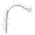
図1は、本発明の空気入りラジアルタイヤの実施形態の一例の子午線方向の半断面図を示す。 FIG. 1 shows a half sectional view in the meridian direction of an example of an embodiment of a pneumatic radial tire of the present invention.
図1において、空気入りラジアルタイヤはタイヤ断面幅の呼びが255以上、かつタイヤ外径が720mm以上の大型構造になっており、1はトレッド部、2はサイドウォール部、3はビード部である。タイヤ断面幅の呼びは、JATMA、ETRTO、TRAのいずれかの規格に規定されたものであればよい。 In FIG. 1, a pneumatic radial tire has a large structure with a tire cross-sectional width of 255 or more and a tire outer diameter of 720 mm or more. 1 is a tread portion, 2 is a sidewall portion, and 3 is a bead portion. . The name of the tire cross-section width may be any as long as it is defined in any standard of JATMA, ETRTO, and TRA.
左右一対のビード部3には、それぞれ環状のビードコア4が埋設され、そのビードコア4の外周に沿って、タイヤ径方向長さLbを短尺化した環状のビードフィラー5が設けられている。カーカス層6は2層で構成され、トレッド部1から左右のサイドウォール部2を経てビード部3に至るように装架され、その両端部がそれぞれビードコア4の周りにビードフィラー5を挟むようにタイヤ内側から外側に折り返されている。トレッド部1には、カーカス層6の外周側に、上下一対のベルト層8がタイヤ1周にわたって配置され、そのベルト層8の外側にベルト層8の全幅及びエッジ部を覆うように複数のベルトカバー層9が配置されている。
The pair of left and
2層のカーカス層6の折り返し部のうち、内層側のカーカス層の折り返し部はビードフィラー5の側面で終端しているが、外層側のカーカス層の折り返し部はベルト層8の端部の内側に挿入されている。このように配置されたカーカス層6とサイドウォール部2との間には、ゴム硬度がサイドウォール部2よりも大きいシート状のゴム補強層7が配置され、また、ビードコア4の周りに、上記カーカス層6よりも内側でビードフィラー5を包み込んでタイヤ内側から外側に折り返すように、ポリアミド繊維からなる繊維補強層10が配置されている。
Of the folded portions of the two carcass layers 6, the folded portion of the inner-layer-side carcass layer terminates at the side surface of the
本発明において、短尺化されたビードフィラー5は、タイヤ径方向長さLbがタイヤ断面高さSHの5〜20%になるように設定されている。さらに好ましくは、ビードフィラー5のタイヤ径方向長さLbを、5〜25mmにすることがよい。このようにビードフィラーを短尺化したことにより、大型化したタイヤの軽量化を可能にし、かつ大型化に伴う荷重負荷に対する荷重耐久性を向上することができる。
In the present invention, the
ビードフィラー5のゴム硬度は、JIS K6253タイプAに準拠するゴム硬度で60〜75にすることが好ましい。ビードフィラー5のゴム硬度をこのような範囲にすることにより、荷重耐久性を向上することができる。ここで、ゴム硬度とは、JIS K6253タイプAに準拠しデュロメータにより温度25℃で測定した値を意味する。
The rubber hardness of the
カーカス層6は、荷重2.0cN/dtex負荷時における伸張率1〜5%の少なくとも1種の有機繊維からなる有機繊維コードで構成する。伸張率がこのような範囲内の有機繊維コードを使用することにより、タイヤ重量を増大することなく周剛性を高くすることができる。このような有機繊維コードを構成する有機繊維としては、例えば、レーヨン繊維、アラミド繊維、ポリパラフェニレン・ベンツビス・オキサゾール(PBO)繊維、ポリケトン繊維などを挙げることができるが、これらのうちでもとりわけレーヨン繊維が好ましい。有機繊維コードは、上記の有機繊維のいずれか1種で構成してもよいが、複数種類を組み合わせて構成してもよい。また、上記に例示した有機繊維と、ナイロン繊維、ポリエステル繊維などその他の有機繊維とを組み合わせて構成してもよい。 The carcass layer 6 is composed of an organic fiber cord made of at least one organic fiber having an elongation rate of 1 to 5% when a load of 2.0 cN / dtex is applied. By using an organic fiber cord having an elongation rate within such a range, the circumferential rigidity can be increased without increasing the tire weight. Examples of the organic fiber constituting such an organic fiber cord include rayon fiber, aramid fiber, polyparaphenylene benzbis oxazole (PBO) fiber, and polyketone fiber. Among these, rayon is particularly preferable. Fiber is preferred. The organic fiber cord may be composed of any one of the above organic fibers, or may be composed of a combination of a plurality of types. Moreover, you may comprise combining the organic fiber illustrated above and other organic fibers, such as a nylon fiber and a polyester fiber.
カーカス層6とサイドウォール部2との間に配置したゴム補強層7は、そのゴム硬度をサイドウォール部2のゴムよりも大きく、かつ厚さが0.5〜2mmのシート状にしたものが使用される。ゴム補強層7のゴム硬度を大きくしたため、周剛性を高くし、タイヤの操縦安定性及び耐久性を向上することができる。ゴム補強層7のゴム硬度としては、JIS K6253タイプAに準拠するゴム硬度で80〜95にし、ビードフィラーよりも硬いゴムにすることが好ましい。このようにビードフィラー5のゴム硬度を低くし、ゴム補強層7のゴム硬度の方を高くしたことにより、タイヤ耐久性をより向上するようにしながらサイド部の周剛性を上げて、操縦安定性を向上することができる。ゴム補強層7の厚さは、0.5mmよりも薄くすると、操縦安定性の維持が難しくなり、また2mmより厚くするとタイヤ耐久性に悪影響を及ぼす。
The rubber reinforcing layer 7 disposed between the carcass layer 6 and the sidewall portion 2 is a sheet having a rubber hardness larger than that of the sidewall portion 2 and having a thickness of 0.5 to 2 mm. used. Since the rubber hardness of the rubber reinforcing layer 7 is increased, the circumferential rigidity can be increased, and the steering stability and durability of the tire can be improved. The rubber hardness of the rubber reinforcing layer 7 is preferably 80 to 95 in terms of rubber hardness according to JIS K6253 type A, and is preferably harder than the bead filler. By reducing the rubber hardness of the
また、ゴム補強層7のタイヤ径方向の長さLrは、タイヤ断面高さSHの40〜60%の範囲にするとよい。タイヤ断面高さSHの40%よりも短いとサイド部の周剛性が十分に得られなくなり、また60%よりも長くすると軽量化が得られなくなる。 The length L r of the rubber reinforcing layer 7 in the tire radial direction is preferably in the range of 40 to 60% of the tire cross-section height SH. If it is shorter than 40% of the tire cross-section height SH, the circumferential rigidity of the side portion cannot be sufficiently obtained, and if it is longer than 60%, weight reduction cannot be obtained.
上述のようにタイヤ径方向の長さLrを有するゴム補強層7のサイドウォール部における位置としては、ベルト層8との関係で設定することが好ましい。すなわち、ゴム補強層7のタイヤ径方向外端7aとベルト層8の端部8aとのタイヤ径方向の距離h1を、タイヤ断面高さSHの5〜25%にするとよい。ゴム補強層7の外端7aとベルト層端部8aとの距離をこのようにすることにより、操縦安定性及び耐久性を向上することができる。
As described above, the position of the rubber reinforcing layer 7 having the length L r in the tire radial direction in the sidewall portion is preferably set in relation to the
また、ゴム補強層7のタイヤ径方向外端7aは、トレット部1のキャップトレッド11に対しては、そのキャップトレッド11の端部とのカーカスラインに沿う距離h2を、5〜20mmの範囲にすることが好ましい。キャップトレッドの端部とゴム補強層7の外端7aとの距離h2を5mm以上にすることにより耐久性を維持し、かつ20mm以下にすることにより操縦安定性を向上することができる。
Also, the tire radial direction outer end 7a of the rubber reinforcement layer 7 is, for the
本発明において、カーカス層の層数は特に制限されるものではないが、好ましくは1層又は2層にするのがよい。カーカス層を1層で構成するときは、その折り返し部の端部を、ベルト層8の端部内側に挿入することが好ましい。このように、所謂ビッド構造にすることにより、操縦安定性及び耐久性を共に向上することができる。
In the present invention, the number of carcass layers is not particularly limited, but is preferably one or two. When the carcass layer is composed of one layer, it is preferable to insert the end portion of the folded portion inside the end portion of the
また、カーカス層を2層で構成するときは、図2に例示するように、2層の折り返し部ともビード部又はサイドウォール部の領域で終端させてもよいが、一方のカーカス層の折り返し部の端部をベルト層端部の内側へ挿入し、他方のカーカス層の折り返し部は、ビード部又はサイドウォール部の領域に留めることが好ましい。さらに好ましくは、ベルト層端部の内側へ挿入する折り返し部の方をタイヤ外側にし、ビード部又はサイドウォール部の領域に留める折り返し部の方をタイヤ内側にするように配置するとよい。これにより、操縦安定性と耐久性を共に向上することができる。 Further, when the carcass layer is composed of two layers, as shown in FIG. 2, both the folded portions of the two layers may be terminated in the region of the bead portion or the sidewall portion, but the folded portion of one carcass layer It is preferable to insert the end of the inside of the belt layer into the end of the belt layer, and to keep the folded portion of the other carcass layer in the region of the bead or sidewall. More preferably, the folded portion inserted into the belt layer end portion is arranged on the tire outer side, and the folded portion fastened in the region of the bead portion or the sidewall portion is arranged on the tire inner side. Thereby, both steering stability and durability can be improved.
カーカス層を2層設けた場合の折り返し部は、外側に位置する折り返し部のタイヤ周方向に対するコード角度は84〜88°、より好ましくは85〜87°にし、その内側に位置する折り返し部とのコード角度差を2°以上にするとよい。内側に位置する折り返し部のタイヤ周方向に対するコード角度としては88〜90°が好ましく、より好ましくは90°にするとよい。 In the case where two carcass layers are provided, the folded portion has a cord angle of 84 to 88 °, more preferably 85 to 87 ° with respect to the tire circumferential direction of the folded portion located on the outer side, and the folded portion located on the inner side. The cord angle difference should be 2 ° or more. The cord angle with respect to the tire circumferential direction of the folded portion located inside is preferably 88 to 90 °, and more preferably 90 °.
本発明において、ビードコア4の周りにビードフィラー5を包み込むように配置した繊維補強層10は、必ずしも必要ではない(図2参照)。しかし、これを設けることにより、軽量化を維持しながら操縦安定性を一層向上することができる。繊維補強層の材料としては、ポリアミド繊維がよい。この繊維補強層10は、図1のように、カーカス層6とビードコア4及びビードフィラー5との間に、介在させるのがよい。
In the present invention, the
繊維補強層10のタイヤ径方向外端10aのビードシートからのタイヤ径方向高さhfとしては、タイヤ断面高さSHの30〜60%にするとよい。このように、繊維補強層10を配置することにより、周剛性をさらに向上し、操縦安定性を向上すると共に、耐久性も向上することができる。
The tire radial direction height h f from the bead sheet of the tire radial direction
本発明の空気入りラジアルタイヤは、前述したようにJATMA、ETRTO、TRAのいずれかに規定されたタイヤ断面幅が255以上で、タイヤ外径が720mm以上の大型構造であるが、特に扁平率を55%以下にした扁平タイヤに適用する場合に、本発明の効果を一層顕著にすることができる。 As described above, the pneumatic radial tire of the present invention is a large structure having a tire cross-sectional width of 255 or more and a tire outer diameter of 720 mm or more as defined in any of JATMA, ETRTO, and TRA. The effect of the present invention can be made more conspicuous when applied to a flat tire of 55% or less.
以下、実施例によって本発明をさらに説明するが、本発明はこれらの実施例に限定されるものではない。 EXAMPLES Hereinafter, although an Example demonstrates this invention further, this invention is not limited to these Examples.
実施例1〜7、比較例1,2
タイヤ構造を図1を基本とし、タイヤサイズが255/55R18、タイヤ外径が730mmで、サイドウォール部ゴムのゴム硬度(JIS K6253タイプA)が56であることを共通条件とし、カーカス層のコードの種類及びカーカス層の構成、ビードフィラーのタイヤ径方向長さLb及びゴム硬度、ゴム補強層の有無及びゴム補強層を有する場合の構成並びにポリアミド繊維補強層の有無及び繊維補強層を有する場合の径方向外端の高さhfを表1に示すように異ならせた9種類の空気入りラジアルタイヤ(実施例1〜7、比較例1,2)を作製した。
Examples 1 to 7, Comparative Examples 1 and 2
The tire structure is based on FIG. 1, the tire size is 255 / 55R18, the tire outer diameter is 730 mm, and the rubber hardness of the sidewall rubber (JIS K6253 type A) is 56. Type and structure of carcass layer, tire radial length L b and rubber hardness of bead filler, presence / absence of rubber reinforcing layer and configuration with rubber reinforcing layer, presence / absence of polyamide fiber reinforcing layer and fiber reinforcing layer Nine types of pneumatic radial tires (Examples 1 to 7 and Comparative Examples 1 and 2) were produced in which the height h f of the radially outer end of each was varied as shown in Table 1.
得られた9種類の空気入りラジアルタイヤについて、下記の試験方法により操縦安定性及び軽量化を評価し、その結果を表1に示す。 For the nine types of pneumatic radial tires obtained, steering stability and weight reduction were evaluated by the following test methods, and the results are shown in Table 1.
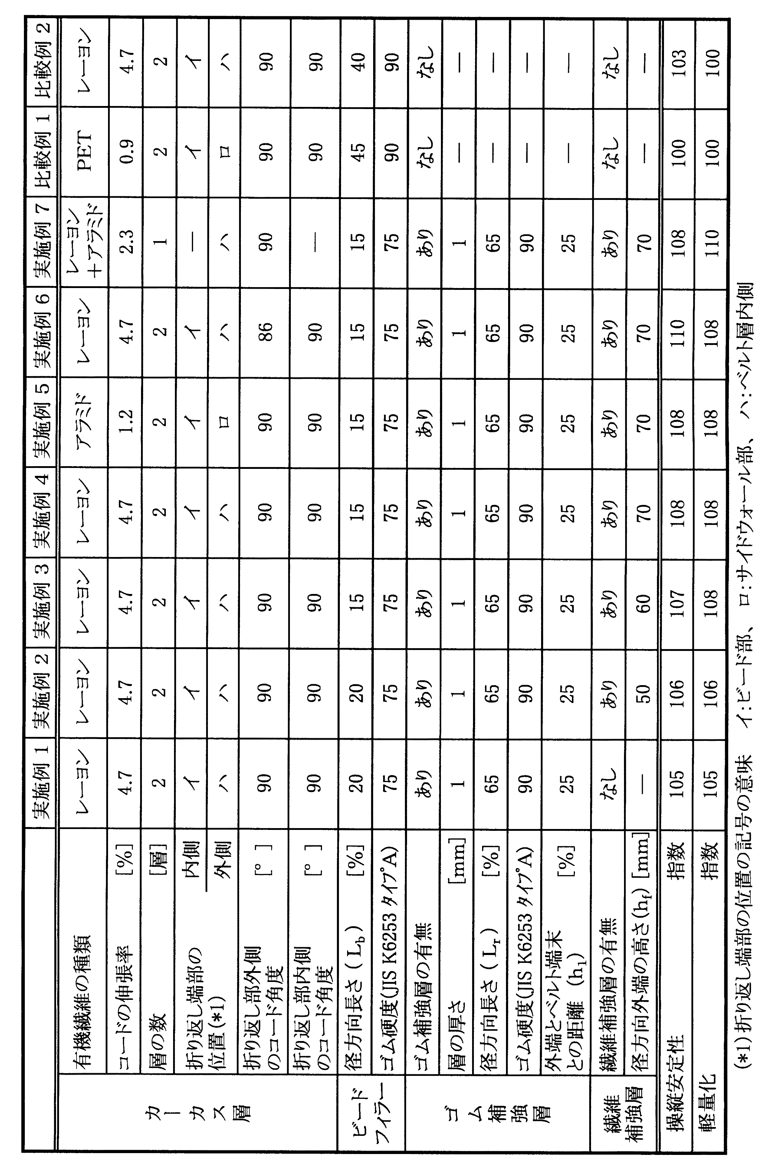
表1において、ビードフィラーのタイヤ径方向長さLb、ゴム補強層のタイヤ径方向長さLr、ゴム補強層のタイヤ径方向外端とベルト層端部との径方向距離h2及び繊維補強層のタイヤ径方向外端のビードシートからの径方向高さhfは、それぞれタイヤ断面高さSHに対する比率[%]で示した。また、カーカス層の折り返し部の端部の位置は、「イ」〜「ハ」の記号で表し、「イ」はカーカス層の折り返し部の端部がビード部で終端していること、「ロ」は折り返し部の端部がサイドウォール部で終端していること、「ハ」は折り返し部の端部がベルト層端部の内側に挿入していることを意味する。なお、カーカスコードの伸張率は、25℃で荷重2.0cN/dtex負荷時における伸張率を測定し、ビードフィラー及びゴム補強層のゴム硬度は、JIS K6253タイプAに準拠しデュロメータにより温度25℃で測定した。 In Table 1, the tire radial length L b of the bead filler, the tire radial direction length L r of the rubber reinforcing layer, the radial distance h 2 and fibers with the tire radial direction outer end and the belt layer end portion of the rubber reinforcing layer The radial height h f from the bead sheet at the outer end in the tire radial direction of the reinforcing layer is indicated by the ratio [%] to the tire cross-section height SH, respectively. In addition, the position of the end portion of the folded portion of the carcass layer is represented by symbols “a” to “c”, and “a” indicates that the end portion of the folded portion of the carcass layer is terminated at the bead portion. "" Means that the end portion of the folded portion is terminated at the sidewall portion, and "C" means that the end portion of the folded portion is inserted inside the belt layer end portion. The elongation of the carcass cord was measured at 25 ° C. under a load of 2.0 cN / dtex, and the rubber hardness of the bead filler and the rubber reinforcing layer was 25 ° C. using a durometer according to JIS K6253 type A. Measured with
操縦安定性
空気入りラジアルタイヤを、サイズ18×8Jのリムにリム組みし、空気圧260kPaにした。このタイヤの操縦安定性を、4.8L排気量の4輪駆動車に装着し、全長2kmのコースにおいて熟練したテストドライバーの官能評価により、走行した際のフィーリングを所定の基準タイヤとの比較において評価した。得られた結果を、比較例1のタイヤの評価結果を100とする指数で示す。この指数値が、大きいほど操縦安定性が優れることを表す。
Steering stability A pneumatic radial tire was assembled on a rim having a size of 18 × 8 J, and the air pressure was set to 260 kPa. Compared with a standard tire, the feeling of running is compared to a predetermined reference tire by the sensory evaluation of a test driver who is experienced in a 2km course, mounted on a 4-wheel drive vehicle with a 4.8L displacement. Evaluated. The obtained results are indicated by an index with the evaluation result of the tire of Comparative Example 1 as 100. The larger the index value, the better the steering stability.
軽量化
比較例1のタイヤ重量を、各実施例のタイヤ重量で割った値を百分率で示した。この値が、大きいほどタイヤ重量が軽いことを表す。
Weight reduction The value obtained by dividing the tire weight of Comparative Example 1 by the tire weight of each Example is shown as a percentage. The larger this value, the lighter the tire weight.
表1の結果から明らかなように、ビードフィラーのタイヤ径方向長さLbをタイヤ断面高さSHの5〜20%に短尺化すると共に、カーカス層を荷重2.0cN/dtex負荷時における伸張率1〜5%の有機繊維コードで構成し、さらにカーカス層とサイドウォール部との間にシート状のゴム補強層を設けたので、軽量化を図りながら高い操縦安定性を維持することが確認された(実施例1〜7)。なお、実施例1〜7の空気入りラジアルタイヤは、比較例1のタイヤと比べて、荷重耐久性が5%以上も向上することが確認された。 Table 1 As is apparent from the results, the tire radial direction length L b of the bead filler as well as shortening of the 5-20% of the tire section height SH, stretching the carcass layer at the time of loading 2.0 cN / dtex load Consists of organic fiber cords with a rate of 1 to 5%, and a sheet-like rubber reinforcement layer is provided between the carcass layer and the side wall, confirming that high steering stability is maintained while achieving weight reduction (Examples 1-7). In addition, it was confirmed that the pneumatic radial tires of Examples 1 to 7 improved the load durability by 5% or more as compared with the tire of Comparative Example 1.
1 トレッド部
2 サイドウォール部
3 ビード部
4 ビードコア
5 ビードフィラー
6 カーカス層
7 ゴム補強層
7a ゴム補強層の径方向外端
8 ベルト層
10 繊維補強層
10a 繊維補強層の径方向外端
DESCRIPTION OF SYMBOLS 1 Tread part 2
Claims (12)
前記ビードフィラーのタイヤ径方向長さLbをタイヤ断面高さSHの5〜20%にし、前記カーカス層を荷重2.0cN/dtex負荷時における伸張率1〜5%の少なくとも1種の有機繊維からなる有機繊維コードで構成すると共に、前記カーカス層とサイドウォール部との間に該サイドウォール部のゴムよりもゴム硬度が大きく、かつ厚さが0.5〜2mmのシート状のゴム補強層を介在させた空気入りラジアルタイヤ。 A pneumatic radial tire having a tire cross-sectional width of 255 or more and a tire outer diameter of 720 mm or more, wherein at least one carcass layer is mounted between a pair of left and right bead cores, and both ends of the carcass layer are In a pneumatic radial tire in which a bead filler is sandwiched around a bead core and folded from the inside to the outside, and a belt layer is arranged on the outer periphery of the carcass layer,
The tire radial direction length L b of the bead filler and 5 to 20% of the tire section height SH, at least one organic fiber extension ratio 1-5% of the carcass layer at the time of loading 2.0 cN / dtex load And a sheet-like rubber reinforcing layer having a rubber hardness between the carcass layer and the sidewall portion that is larger than the rubber of the sidewall portion and having a thickness of 0.5 to 2 mm. Pneumatic radial tire with intervening.
Priority Applications (4)
| Application Number | Priority Date | Filing Date | Title |
|---|---|---|---|
| JP2007161696A JP2009001073A (en) | 2007-06-19 | 2007-06-19 | Pneumatic radial tire |
| US12/128,162 US8025084B2 (en) | 2007-06-19 | 2008-05-28 | Pneumatic radial tire |
| DE602008000607T DE602008000607D1 (en) | 2007-06-19 | 2008-06-04 | Pneumatic radial tire |
| EP08010191A EP2006123B1 (en) | 2007-06-19 | 2008-06-04 | Pneumatic radial tire |
Applications Claiming Priority (1)
| Application Number | Priority Date | Filing Date | Title |
|---|---|---|---|
| JP2007161696A JP2009001073A (en) | 2007-06-19 | 2007-06-19 | Pneumatic radial tire |
Publications (1)
| Publication Number | Publication Date |
|---|---|
| JP2009001073A true JP2009001073A (en) | 2009-01-08 |
Family
ID=39739733
Family Applications (1)
| Application Number | Title | Priority Date | Filing Date |
|---|---|---|---|
| JP2007161696A Withdrawn JP2009001073A (en) | 2007-06-19 | 2007-06-19 | Pneumatic radial tire |
Country Status (4)
| Country | Link |
|---|---|
| US (1) | US8025084B2 (en) |
| EP (1) | EP2006123B1 (en) |
| JP (1) | JP2009001073A (en) |
| DE (1) | DE602008000607D1 (en) |
Cited By (8)
| Publication number | Priority date | Publication date | Assignee | Title |
|---|---|---|---|---|
| JP2011025823A (en) * | 2009-07-24 | 2011-02-10 | Bridgestone Corp | Pneumatic tire |
| JP2011093395A (en) * | 2009-10-28 | 2011-05-12 | Bridgestone Corp | Pneumatic tire |
| WO2011129444A1 (en) * | 2010-04-15 | 2011-10-20 | 株式会社ブリヂストン | Pneumatic tire |
| JP2011225007A (en) * | 2010-04-15 | 2011-11-10 | Bridgestone Corp | Pneumatic tire |
| JP2012056519A (en) * | 2010-09-10 | 2012-03-22 | Bridgestone Corp | Pneumatic radial tire |
| JP2012148682A (en) * | 2011-01-19 | 2012-08-09 | Bridgestone Corp | Pneumatic tire |
| WO2015008752A1 (en) | 2013-07-17 | 2015-01-22 | 株式会社ブリヂストン | Tire |
| US8991459B2 (en) | 2011-11-10 | 2015-03-31 | Bridgestone Americas Tire Operations, Llc | Reinforced radial tire |
Families Citing this family (4)
| Publication number | Priority date | Publication date | Assignee | Title |
|---|---|---|---|---|
| JP5277928B2 (en) * | 2008-12-15 | 2013-08-28 | 横浜ゴム株式会社 | Pneumatic tire |
| DE102014207193B4 (en) | 2014-04-15 | 2023-06-29 | Continental Reifen Deutschland Gmbh | Vehicle Pneumatic Tires |
| CN109835123B (en) * | 2019-01-29 | 2021-09-03 | 安徽佳通乘用子午线轮胎有限公司 | Pneumatic tire capable of reducing rolling resistance |
| JP2020203612A (en) * | 2019-06-18 | 2020-12-24 | 株式会社ブリヂストン | tire |
Family Cites Families (13)
| Publication number | Priority date | Publication date | Assignee | Title |
|---|---|---|---|---|
| JP2652856B2 (en) | 1987-09-22 | 1997-09-10 | 横浜ゴム株式会社 | Pneumatic tire |
| JPH045110A (en) * | 1990-04-20 | 1992-01-09 | Sumitomo Rubber Ind Ltd | Radial tire for motorcycle |
| DE4020531A1 (en) * | 1990-06-28 | 1992-01-02 | Continental Ag | VEHICLE TIRES |
| JP3226606B2 (en) * | 1992-06-19 | 2001-11-05 | 横浜ゴム株式会社 | Pneumatic tire |
| JP3229381B2 (en) * | 1992-08-27 | 2001-11-19 | 横浜ゴム株式会社 | Pneumatic radial tire |
| ES2133493T3 (en) * | 1993-10-12 | 1999-09-16 | Bridgestone Corp | MOLD FOR VULCANIZING A PNEUMATIC COVER. |
| JP3706181B2 (en) * | 1994-12-09 | 2005-10-12 | 株式会社ブリヂストン | Pneumatic radial tire |
| JP3703935B2 (en) | 1997-03-12 | 2005-10-05 | 株式会社ブリヂストン | Pneumatic radial tire |
| JP3868133B2 (en) * | 1998-12-11 | 2007-01-17 | 横浜ゴム株式会社 | Pneumatic radial tire |
| JP4179462B2 (en) * | 2003-06-17 | 2008-11-12 | 横浜ゴム株式会社 | Pneumatic tire |
| JP4464700B2 (en) * | 2004-01-28 | 2010-05-19 | 住友ゴム工業株式会社 | Pneumatic tire and manufacturing method thereof |
| JP4616627B2 (en) | 2004-12-02 | 2011-01-19 | 住友ゴム工業株式会社 | Pneumatic tire and manufacturing method thereof |
| JP4375804B2 (en) * | 2005-01-21 | 2009-12-02 | 株式会社ブリヂストン | Pneumatic tire |
-
2007
- 2007-06-19 JP JP2007161696A patent/JP2009001073A/en not_active Withdrawn
-
2008
- 2008-05-28 US US12/128,162 patent/US8025084B2/en not_active Expired - Fee Related
- 2008-06-04 EP EP08010191A patent/EP2006123B1/en not_active Expired - Fee Related
- 2008-06-04 DE DE602008000607T patent/DE602008000607D1/en active Active
Cited By (9)
| Publication number | Priority date | Publication date | Assignee | Title |
|---|---|---|---|---|
| JP2011025823A (en) * | 2009-07-24 | 2011-02-10 | Bridgestone Corp | Pneumatic tire |
| JP2011093395A (en) * | 2009-10-28 | 2011-05-12 | Bridgestone Corp | Pneumatic tire |
| WO2011129444A1 (en) * | 2010-04-15 | 2011-10-20 | 株式会社ブリヂストン | Pneumatic tire |
| JP2011225007A (en) * | 2010-04-15 | 2011-11-10 | Bridgestone Corp | Pneumatic tire |
| JP2012056519A (en) * | 2010-09-10 | 2012-03-22 | Bridgestone Corp | Pneumatic radial tire |
| JP2012148682A (en) * | 2011-01-19 | 2012-08-09 | Bridgestone Corp | Pneumatic tire |
| US8991459B2 (en) | 2011-11-10 | 2015-03-31 | Bridgestone Americas Tire Operations, Llc | Reinforced radial tire |
| WO2015008752A1 (en) | 2013-07-17 | 2015-01-22 | 株式会社ブリヂストン | Tire |
| JPWO2015008752A1 (en) * | 2013-07-17 | 2017-03-02 | 株式会社ブリヂストン | tire |
Also Published As
| Publication number | Publication date |
|---|---|
| DE602008000607D1 (en) | 2010-03-18 |
| EP2006123A1 (en) | 2008-12-24 |
| US20080314496A1 (en) | 2008-12-25 |
| EP2006123B1 (en) | 2010-01-27 |
| US8025084B2 (en) | 2011-09-27 |
Similar Documents
| Publication | Publication Date | Title |
|---|---|---|
| JP2009001073A (en) | Pneumatic radial tire | |
| EP0638445B2 (en) | Pneumatic radial tyre | |
| US20090095397A1 (en) | Floating two-ply tire | |
| JP2009035229A (en) | Pneumatic tire | |
| JP2018111433A (en) | Pneumatic tire for heavy load | |
| WO2019230773A1 (en) | Pneumatic tire | |
| JP2008279796A (en) | Pneumatic tire | |
| US8037913B2 (en) | Pneumatic tire with single non-continuous carcass ply | |
| EP3599111B1 (en) | Pneumatic tire | |
| JP2014051232A (en) | Pneumatic tire | |
| JP2009035230A (en) | Pneumatic tire | |
| JP7028225B2 (en) | Pneumatic tires | |
| JP2007153276A (en) | Pneumatic run flat radial tire | |
| JP6315651B2 (en) | Pneumatic tire | |
| JP2007276694A (en) | Pneumatic tire | |
| JP4586344B2 (en) | Pneumatic tire | |
| US20100051162A1 (en) | Modular two-ply tire with directional side plies | |
| JP2007030719A (en) | Pneumatic radial tire | |
| CN112996675B (en) | Run flat tire | |
| JP6087776B2 (en) | Pneumatic semi-radial tire | |
| JP2011126400A (en) | Pneumatic radial tire | |
| JP2006193126A (en) | Pneumatic tire | |
| JP2010132218A (en) | Pneumatic radial tire | |
| US20100051164A1 (en) | Modular ply tire with dissimilar materials | |
| JP6537184B2 (en) | Pneumatic tire |
Legal Events
| Date | Code | Title | Description |
|---|---|---|---|
| A521 | Written amendment |
Free format text: JAPANESE INTERMEDIATE CODE: A523 Effective date: 20081024 |
|
| A131 | Notification of reasons for refusal |
Free format text: JAPANESE INTERMEDIATE CODE: A131 Effective date: 20081118 |
|
| A761 | Written withdrawal of application |
Free format text: JAPANESE INTERMEDIATE CODE: A761 Effective date: 20090116 |