JP2008546918A - Fluid jet cutting method - Google Patents
Fluid jet cutting method Download PDFInfo
- Publication number
- JP2008546918A JP2008546918A JP2008517015A JP2008517015A JP2008546918A JP 2008546918 A JP2008546918 A JP 2008546918A JP 2008517015 A JP2008517015 A JP 2008517015A JP 2008517015 A JP2008517015 A JP 2008517015A JP 2008546918 A JP2008546918 A JP 2008546918A
- Authority
- JP
- Japan
- Prior art keywords
- fluid jet
- fluid
- cutting
- coating composition
- fiber
- Prior art date
- Legal status (The legal status is an assumption and is not a legal conclusion. Google has not performed a legal analysis and makes no representation as to the accuracy of the status listed.)
- Pending
Links
Images


Classifications
-
- B—PERFORMING OPERATIONS; TRANSPORTING
- B26—HAND CUTTING TOOLS; CUTTING; SEVERING
- B26F—PERFORATING; PUNCHING; CUTTING-OUT; STAMPING-OUT; SEVERING BY MEANS OTHER THAN CUTTING
- B26F3/00—Severing by means other than cutting; Apparatus therefor
-
- B—PERFORMING OPERATIONS; TRANSPORTING
- B26—HAND CUTTING TOOLS; CUTTING; SEVERING
- B26F—PERFORATING; PUNCHING; CUTTING-OUT; STAMPING-OUT; SEVERING BY MEANS OTHER THAN CUTTING
- B26F3/00—Severing by means other than cutting; Apparatus therefor
- B26F3/004—Severing by means other than cutting; Apparatus therefor by means of a fluid jet
-
- B—PERFORMING OPERATIONS; TRANSPORTING
- B24—GRINDING; POLISHING
- B24C—ABRASIVE OR RELATED BLASTING WITH PARTICULATE MATERIAL
- B24C5/00—Devices or accessories for generating abrasive blasts
- B24C5/02—Blast guns, e.g. for generating high velocity abrasive fluid jets for cutting materials
- B24C5/04—Nozzles therefor
-
- B—PERFORMING OPERATIONS; TRANSPORTING
- B26—HAND CUTTING TOOLS; CUTTING; SEVERING
- B26D—CUTTING; DETAILS COMMON TO MACHINES FOR PERFORATING, PUNCHING, CUTTING-OUT, STAMPING-OUT OR SEVERING
- B26D7/00—Details of apparatus for cutting, cutting-out, stamping-out, punching, perforating, or severing by means other than cutting
- B26D7/08—Means for treating work or cutting member to facilitate cutting
-
- B—PERFORMING OPERATIONS; TRANSPORTING
- B26—HAND CUTTING TOOLS; CUTTING; SEVERING
- B26D—CUTTING; DETAILS COMMON TO MACHINES FOR PERFORATING, PUNCHING, CUTTING-OUT, STAMPING-OUT OR SEVERING
- B26D7/00—Details of apparatus for cutting, cutting-out, stamping-out, punching, perforating, or severing by means other than cutting
- B26D7/27—Means for performing other operations combined with cutting
- B26D7/34—Means for performing other operations combined with cutting for applying a coating, such as butter, to cut product
-
- F—MECHANICAL ENGINEERING; LIGHTING; HEATING; WEAPONS; BLASTING
- F01—MACHINES OR ENGINES IN GENERAL; ENGINE PLANTS IN GENERAL; STEAM ENGINES
- F01N—GAS-FLOW SILENCERS OR EXHAUST APPARATUS FOR MACHINES OR ENGINES IN GENERAL; GAS-FLOW SILENCERS OR EXHAUST APPARATUS FOR INTERNAL COMBUSTION ENGINES
- F01N3/00—Exhaust or silencing apparatus having means for purifying, rendering innocuous, or otherwise treating exhaust
- F01N3/08—Exhaust or silencing apparatus having means for purifying, rendering innocuous, or otherwise treating exhaust for rendering innocuous
- F01N3/10—Exhaust or silencing apparatus having means for purifying, rendering innocuous, or otherwise treating exhaust for rendering innocuous by thermal or catalytic conversion of noxious components of exhaust
- F01N3/24—Exhaust or silencing apparatus having means for purifying, rendering innocuous, or otherwise treating exhaust for rendering innocuous by thermal or catalytic conversion of noxious components of exhaust characterised by constructional aspects of converting apparatus
- F01N3/28—Construction of catalytic reactors
- F01N3/2839—Arrangements for mounting catalyst support in housing, e.g. with means for compensating thermal expansion or vibration
- F01N3/2853—Arrangements for mounting catalyst support in housing, e.g. with means for compensating thermal expansion or vibration using mats or gaskets between catalyst body and housing
-
- Y—GENERAL TAGGING OF NEW TECHNOLOGICAL DEVELOPMENTS; GENERAL TAGGING OF CROSS-SECTIONAL TECHNOLOGIES SPANNING OVER SEVERAL SECTIONS OF THE IPC; TECHNICAL SUBJECTS COVERED BY FORMER USPC CROSS-REFERENCE ART COLLECTIONS [XRACs] AND DIGESTS
- Y10—TECHNICAL SUBJECTS COVERED BY FORMER USPC
- Y10T—TECHNICAL SUBJECTS COVERED BY FORMER US CLASSIFICATION
- Y10T29/00—Metal working
- Y10T29/49—Method of mechanical manufacture
- Y10T29/49345—Catalytic device making
-
- Y—GENERAL TAGGING OF NEW TECHNOLOGICAL DEVELOPMENTS; GENERAL TAGGING OF CROSS-SECTIONAL TECHNOLOGIES SPANNING OVER SEVERAL SECTIONS OF THE IPC; TECHNICAL SUBJECTS COVERED BY FORMER USPC CROSS-REFERENCE ART COLLECTIONS [XRACs] AND DIGESTS
- Y10—TECHNICAL SUBJECTS COVERED BY FORMER USPC
- Y10T—TECHNICAL SUBJECTS COVERED BY FORMER US CLASSIFICATION
- Y10T83/00—Cutting
- Y10T83/04—Processes
- Y10T83/0591—Cutting by direct application of fluent pressure to work
-
- Y—GENERAL TAGGING OF NEW TECHNOLOGICAL DEVELOPMENTS; GENERAL TAGGING OF CROSS-SECTIONAL TECHNOLOGIES SPANNING OVER SEVERAL SECTIONS OF THE IPC; TECHNICAL SUBJECTS COVERED BY FORMER USPC CROSS-REFERENCE ART COLLECTIONS [XRACs] AND DIGESTS
- Y10—TECHNICAL SUBJECTS COVERED BY FORMER USPC
- Y10T—TECHNICAL SUBJECTS COVERED BY FORMER US CLASSIFICATION
- Y10T83/00—Cutting
- Y10T83/364—By fluid blast and/or suction
Abstract
無機繊維材料物品のような繊維材料のための流体ジェット切断方法を提供する。流体ジェット切断方法に用いるための流体組成物も、提供する。切断流体組成物は、キャリア流体および繊維材料の切断面のためのコーティング組成物を含有する。繊維材料の流体ジェット切断方法を実施するための装置も、提供する。
【選択図】図2CA fluid jet cutting method for fiber materials such as inorganic fiber material articles is provided. A fluid composition for use in a fluid jet cutting method is also provided. The cutting fluid composition contains a coating composition for the carrier fluid and the cut surface of the fibrous material. An apparatus for performing a fluid jet cutting method of a textile material is also provided.
[Selection] Figure 2C
Description
流体ジェット切断方法を開示する。より詳細には、繊維材料のための流体ジェット切断方法および流体ジェット切断方法に用いるための流体組成物を開示する。 A fluid jet cutting method is disclosed. More particularly, fluid jet cutting methods for fiber materials and fluid compositions for use in fluid jet cutting methods are disclosed.
水ジェット切断あるいは液体ジェット切断としても知られる、流体ジェット切断の方法は、1970年代に開発された。その方法は、流体を、ほぼ約10,000乃至約60,000psi(6.9×10⁷乃至4.1×10⁸Pa)の範囲の圧力に加圧するステップと、加圧流体を流体ジェット装置のノズルから放出して材料を切断するステップと、を含む。 A method of fluid jet cutting, also known as water jet cutting or liquid jet cutting, was developed in the 1970s. The method includes the steps of pressurizing the fluid to a pressure in the range of about 10,000 to about 60,000 psi (6.9 × 10 7 to 4.1 × 10 8 Pa), and the pressurized fluid to the fluid jet apparatus. And discharging the material from the nozzle and cutting the material.
研磨ジェット切断の方法が、流体ジェット切断の方法に関連する。流体ジェット切断方法と同様に、流体は非常に高圧に加圧される。研磨粒子が、切断装置のノズルを出る前に、加圧流体中に同伴される。研磨粒子を切断流体に加えることにより、本方法で金属、金属合金、セラミック、およびプラスチックのような、より硬い材料を切り離すことができる。 The method of abrasive jet cutting is related to the method of fluid jet cutting. Similar to the fluid jet cutting method, the fluid is pressurized to a very high pressure. Abrasive particles are entrained in the pressurized fluid before exiting the nozzle of the cutting device. By adding abrasive particles to the cutting fluid, harder materials such as metals, metal alloys, ceramics, and plastics can be separated in this manner.
何年にもわたって、無機繊維材料は、断熱、電気的絶縁、および防音用途に利用されてきている。無機繊維材料は、また、自動車の排気ガス処理装置用途に用いられてきている。特定の用途に依存して、無機繊維材料を、ブランケット、板、フェルト、マット、産業織物などのようなあらゆる製品形態に加工することができる。 Over the years, inorganic fiber materials have been utilized for thermal insulation, electrical insulation, and soundproofing applications. Inorganic fiber materials have also been used in automotive exhaust gas treatment equipment applications. Depending on the specific application, the inorganic fiber material can be processed into any product form such as blankets, boards, felts, mats, industrial fabrics and the like.
自動車およびディーゼルエンジンの排気ガスを処理するための装置は、一般的に、ハウジングと、排気ガス中の一酸化炭素および炭化水素の酸化および窒素酸化物の還元をもたらすために用いられる触媒を保持するための脆弱触媒支持構造と、を収容する。脆弱触媒支持構造は、取付け材料あるいは支持材料によって、ハウジングの内面と脆弱触媒支持構造の外面との間のギャップあるいは空間内に取付けられる。 Apparatus for treating exhaust gases of automobiles and diesel engines generally holds a housing and a catalyst used to effect oxidation of carbon monoxide and hydrocarbons and reduction of nitrogen oxides in the exhaust gas And a brittle catalyst support structure for housing. The fragile catalyst support structure is mounted in a gap or space between the inner surface of the housing and the outer surface of the fragile catalyst support structure by an attachment material or support material.
脆弱触媒支持構造を、自動車あるいはディーゼルエンジンの通常の作動中経験される熱的衝撃および機械的衝撃および他のストレスから保護するために、無機繊維材料の少なくとも1つのプライあるいは層を、脆弱触媒支持構造とハウジングとの間のギャップ内に配置して、脆弱触媒支持構造を保護し、さもなければそれをハウジング内の所定の位置に保持することが知られている。 In order to protect the fragile catalyst support structure from thermal and mechanical shocks and other stresses experienced during normal operation of an automobile or diesel engine, at least one ply or layer of inorganic fiber material is supported by the fragile catalyst support. It is known to place in the gap between the structure and the housing to protect the brittle catalyst support structure or otherwise hold it in place in the housing.
脆弱触媒支持構造を排気ガス処理装置のハウジング内に取付けるために用いられる繊維材料は、一般的に、ダイカットあるいはスタンピングによって、排気ガス処理装置への組み込みに適したサイズおよび形状に加工される。無機繊維材料、例えば耐火セラミック繊維の比較的脆い性質により、ダイカットあるいはスタンピング加工により、飛散粒子塵を生じることがある。この粒子塵は、皮膚、目および気道を刺激することがあり、マットを製造する労働者および繊維マットを排気ガス処理装置の中に据付ける労働者に心配をもたらす。 The fiber material used to attach the fragile catalyst support structure within the housing of the exhaust gas treatment device is generally processed by die cutting or stamping to a size and shape suitable for incorporation into the exhaust gas treatment device. Due to the relatively brittle nature of inorganic fiber materials such as refractory ceramic fibers, die-cutting or stamping can cause scattered particulate dust. This particulate dust can irritate the skin, eyes and respiratory tract, and is a concern for workers who manufacture mats and workers who install fiber mats in exhaust gas treatment equipment.
従って、これらの無機材料のダイカットあるいはスタンピングと伝統的に関連した刺激性の飛散繊維塵の発生を最小にしながら、無機繊維材料の複雑且つ正確な切断を提供することのできる改良された方法の必要が当技術分野に存在する。 Accordingly, there is a need for an improved method that can provide complex and accurate cutting of inorganic fiber materials while minimizing the generation of irritating scattered fiber dust traditionally associated with die cutting or stamping of these inorganic materials. Exists in the art.
無機繊維材料の切断中、前記無機繊維材料からの塵発生を減じるための方法が提供され、前記方法は、前記無機繊維材料を加圧流体ジェットに接触させるステップと、前記無機繊維材料を前記流体ジェットで切断するステップと、を含む。 A method is provided for reducing dust generation from the inorganic fiber material during cutting of the inorganic fiber material, the method comprising contacting the inorganic fiber material with a pressurized fluid jet; Cutting with a jet.
流体ジェット切断方法が提供され、この方法は、繊維材料を加圧流体ジェットに接触させるステップを含み、前記流体ジェットは、キャリア流体および前記繊維材料のためのコーティング剤を含有し、前記繊維材料を前記流体ジェットで切断するステップを含む。 A fluid jet cutting method is provided, the method comprising contacting a fibrous material with a pressurized fluid jet, the fluid jet containing a carrier fluid and a coating agent for the fibrous material, Cutting with the fluid jet.
他の実施形態によれば、繊維材料の高圧流体ジェット切断のための流体組成物も、提供され、流体組成物は、キャリア流体および前記繊維材料のためのコーティング剤からなる。 According to another embodiment, a fluid composition for high pressure fluid jet cutting of a fiber material is also provided, the fluid composition comprising a carrier fluid and a coating agent for the fiber material.
更なる実施形態によれば、繊維材料の流体ジェット切断のための装置が提供され、前記装置は、加圧流体ジェットを作るためのポンプと、前記繊維材料のための切断流体を収容するリザーバと、コーティング組成物を選択的に有する前記切断流体と、前記切断流体を受け入れるための入口および前記切断流体を繊維基板上に放出するための出口を有するノズルと、を含む。 According to a further embodiment, an apparatus for fluid jet cutting of fiber material is provided, the apparatus comprising a pump for creating a pressurized fluid jet, and a reservoir containing cutting fluid for the fiber material. The cutting fluid selectively having a coating composition, and a nozzle having an inlet for receiving the cutting fluid and an outlet for discharging the cutting fluid onto a fiber substrate.
流体ジェット切断装置は、加圧流体ジェットを作るためのポンプと、前記切断流体および前記コーティング組成物を別々に収容するためのリザーバと、前記切断流体の加圧流体ジェットを受け入れるための第1の入口と、前記コーティング組成物を受け入れるための第2の入口と、前記切断流体およびコーティング組成物を合流させるための容積と、を有するノズルと、前記流体ジェットおよびコーティング組成物を放出する出口と、を含むのがよい。 A fluid jet cutting device includes a pump for creating a pressurized fluid jet, a reservoir for separately containing the cutting fluid and the coating composition, and a first for receiving a pressurized fluid jet of the cutting fluid. A nozzle having an inlet, a second inlet for receiving the coating composition, a volume for combining the cutting fluid and the coating composition, and an outlet for discharging the fluid jet and the coating composition; Should be included.
更なる実施形態によれば、流体ジェット切断方法は、繊維材料を加圧流体ジェットに接触させるステップを含み、前記流体ジェットは、キャリア流体および前記繊維材料のための所望の薬品を含有し、前記繊維材料を前記流体ジェットで切断するステップと、前記繊維材料の少なくとも一部分上に前記所望の薬品を付着させるステップと、を含む。 According to a further embodiment, a fluid jet cutting method includes contacting a fibrous material with a pressurized fluid jet, the fluid jet containing a carrier fluid and a desired chemical for the fibrous material, Cutting a fiber material with the fluid jet and depositing the desired chemical on at least a portion of the fiber material.
排気ガス処理装置のための流体ジェット切断繊維取付けマットも、提供され、前記取付けマットは、流体ジェット切断縁面の少なくとも一部分に付着したコーティングを含む。 A fluid jet cutting fiber mounting mat for an exhaust gas treatment device is also provided, the mounting mat including a coating deposited on at least a portion of the fluid jet cutting edge.
排気ガス処理装置は、ハウジングと、前記ハウジング内に弾性的に取付けられた脆弱触媒支持構造と、前記ハウジングと前記脆弱触媒支持構造との間のギャップに配置された流体ジェット切断無機繊維取付けマットと、を含み、前記取付けマットは、流体ジェット切断縁面の少なくとも一部分に付着したコーティングを更に含む。 An exhaust gas treatment device includes a housing, a brittle catalyst support structure elastically mounted in the housing, and a fluid jet cutting inorganic fiber mounting mat disposed in a gap between the housing and the brittle catalyst support structure. The mounting mat further includes a coating deposited on at least a portion of the fluid jet cutting edge.
流体ジェット切断方法は、繊維材料を切断するために利用される。流体ジェット切断方法は、繊維材料の表面を高圧流体ジェット流に接触させ、あるいはさもなければ曝すことと、繊維材料を所定の切断経路に沿って加圧流体ジェットで切断することと、を含む。流体ジェットは、繊維材料を所定の切断経路に沿って切り離すので、所望の薬品が流体ジェット切断方法によって露出された繊維材料の縁面の少なくとも一部分に同時に付着する。 The fluid jet cutting method is utilized to cut fiber material. The fluid jet cutting method includes contacting or otherwise exposing the surface of the fiber material to a high pressure fluid jet stream and cutting the fiber material with a pressurized fluid jet along a predetermined cutting path. The fluid jet cuts the fiber material along a predetermined cutting path so that the desired chemicals are simultaneously deposited on at least a portion of the edge of the fiber material exposed by the fluid jet cutting method.
例示的実施形態によれば、流体ジェット切断方法は、繊維材料の表面を高圧流体ジェット流に接触させ、あるいはさもなければ曝すことと、繊維材料を所定の切断経路に沿って加圧流体ジェットで切断することを含む。流体ジェットは、繊維材料を所定の切断経路に沿って切り離すので、コーティング剤が流体ジェット切断方法によって露出された繊維材料の縁面の少なくとも一部分に付着する。 According to an exemplary embodiment, a fluid jet cutting method includes contacting a fiber material surface with a high pressure fluid jet stream or otherwise exposing the fiber material with a pressurized fluid jet along a predetermined cutting path. Including cutting. The fluid jet cuts the fiber material along a predetermined cutting path so that the coating agent adheres to at least a portion of the edge of the fiber material exposed by the fluid jet cutting method.
繊維材料の縁面は、ウィッキング工程によってコーティング剤を吸収する。繊維材料を流体ジェット方法によって切断した後、繊維材料の切断ピースを、流体ジェット切断装置から取り出し、乾燥させて切断工程中吸収したいかなる余分な水分をも取り除く。切断繊維材料は、空気乾燥およびオーブンでの加熱乾燥のような、いかなる在来の乾燥処理によって乾燥することができる。一旦、切断繊維材料が乾燥したら、コーティング剤が繊維材料の露出した縁にシールを形成する。 The edge surface of the fiber material absorbs the coating agent by a wicking process. After the fiber material is cut by the fluid jet method, the cut piece of fiber material is removed from the fluid jet cutting device and dried to remove any excess moisture absorbed during the cutting process. The cut fiber material can be dried by any conventional drying process, such as air drying and oven drying. Once the cut fiber material is dry, the coating agent forms a seal on the exposed edge of the fiber material.
流体ジェット切断装置のポンプによって作られた流体ジェット流の、繊維基板を切断するために必要とされる最小圧力はない。ポンプによって作られ、且つ流体ジェット切断装置の出力ノズルから放出されたジェット流は、1枚の繊維基板あるいは、所望の用途耐性に適合するための所定の厚さを有するスタックあるいは複数の繊維基板を切断するのに十分な圧力まで簡単に加圧される。当業者は、流体ジェット切断装置で切断されることが望まれる繊維基板の厚さに基づいて適当な圧力を容易に選択することができる。 There is no minimum pressure required to cut the fiber substrate of the fluid jet stream created by the pump of the fluid jet cutting device. The jet stream produced by the pump and emitted from the output nozzle of the fluid jet cutting device can be a single fiber substrate or a stack or a plurality of fiber substrates having a predetermined thickness to meet the desired application tolerance. It is simply pressurized to a pressure sufficient to cut. One skilled in the art can readily select an appropriate pressure based on the thickness of the fiber substrate desired to be cut with the fluid jet cutting device.
限定されないある実施形態によれば、ポンプによって作られた、且つ流体ジェット切断装置のノズルから放出された流体ジェット流は、5,000psi(3.4×10⁷Pa)以上の圧力まで加圧される。他の実施形態によれば、ポンプによって作られた、且つ流体ジェット切断装置のノズルの出力から放出された流体ジェット流は、少なくとも10,000psi(6.9×10⁷Pa)の圧力まで加圧される。更なる実施形態によれば、流体ジェット流は、少なくとも60,000psi(4.1×10⁸Pa)の圧力まで加圧されるのがよい。加圧流体ジェット流を用いることによって、繊維材料物品の全体の厚さを通して正確な切断をすることができる。 According to one non-limiting embodiment, the fluid jet stream created by the pump and discharged from the nozzle of the fluid jet cutting device is pressurized to a pressure of 5,000 psi (3.4 × 10 7 Pa) or higher. The According to another embodiment, the fluid jet stream created by the pump and discharged from the output of the nozzle of the fluid jet cutting device is pressurized to a pressure of at least 10,000 psi (6.9 × 10 7 Pa). Is done. According to a further embodiment, the fluid jet stream may be pressurized to a pressure of at least 60,000 psi (4.1 × 10 8 Pa). By using a pressurized fluid jet stream, an accurate cut can be made through the entire thickness of the fibrous material article.
特定の用途に依存して、繊維材料は、広範な製品形態に切断することができる。従って、流体ジェット切断方法は、限定ではなく、繊維ブランケット、板、フェルト、マット、産業織物などのいかなる数の無機繊維材料製品形態を切断するのに適している。 Depending on the specific application, the fiber material can be cut into a wide variety of product forms. Thus, the fluid jet cutting method is suitable for cutting any number of inorganic fiber material product forms such as, but not limited to, fiber blankets, boards, felts, mats, industrial fabrics and the like.
高圧流体ジェット切断方法のための流体組成物は、キャリア流体および繊維材料のためのコーティング剤を含む。殆どの場合、流体ジェット切断組成物のキャリア流体は、水である、なぜならば水はコスト効率が良く、環境に優しく、流体ジェット切断装置の構成部品および繊維マットと化学的に不活性だからである。しかしながら、流体ジェット装置および切断されるべき繊維材料と化学的に不活性であるいかなる他のキャリア流体を利用することができることに留意すべきである。 The fluid composition for the high pressure fluid jet cutting method includes a carrier fluid and a coating agent for the fiber material. In most cases, the carrier fluid of the fluid jet cutting composition is water because it is cost effective, environmentally friendly and chemically inert with the components of the fluid jet cutting device and the fiber mat. . However, it should be noted that any other carrier fluid that is chemically inert with the fluid jet device and the fiber material to be cut can be utilized.
流体ジェット切断組成物は、また、本方法によって切断されるべき繊維材料のためのコーティング組成物を含有する。限定でなく、流体ジェット切断組成物に含まれるコーティング組成物は、キャリア流体と適合し、流体ジェット装置および切断されるべき繊維材料に化学的に不活性であり、且つ無機繊維材料の表面をコーティングするために伝統的に利用される、いかなるコーティング組成物からなってもよい。限定でなく、適当なコーティング組成物は、ポリマーコーティング材料溶液あるいは懸濁液を含む。限定でなく、流体ジェット切断組成物に含まれるのがよい適当なポリマーコーティング材料は、アクリルポリマー、メタクリルポリマー、ポリビニルアルコール、スターチポリマー、ウレタンポリマー、酢酸ビニルポリマー、およびラテックスの溶液あるいは懸濁液を含む。限定でなく、流体ジェット切断方法のコーティング組成物として利用することができる適当なラテックスは、アクリルラテックスである。ある実施形態によれば、流体ジェット切断組成物は、キャリア流体として水と、繊維材料のためのコーティング材料としてアクリルラテックスと、を含有する。 The fluid jet cutting composition also contains a coating composition for the fiber material to be cut by the present method. Without limitation, the coating composition included in the fluid jet cutting composition is compatible with the carrier fluid, is chemically inert to the fluid jet device and the fiber material to be cut, and coats the surface of the inorganic fiber material. It may consist of any coating composition traditionally utilized for Without limitation, suitable coating compositions include polymer coating material solutions or suspensions. Without limitation, suitable polymer coating materials that may be included in the fluid jet cutting composition include acrylic polymer, methacrylic polymer, polyvinyl alcohol, starch polymer, urethane polymer, vinyl acetate polymer, and latex solutions or suspensions. Including. A suitable latex that can be utilized as a coating composition for the fluid jet cutting process, without limitation, is an acrylic latex. According to certain embodiments, the fluid jet cutting composition contains water as the carrier fluid and acrylic latex as the coating material for the fiber material.
流体ジェット切断組成物は、研磨材料を含んでもよいし、含まなくてもよい。流体ジェット切断組成物が研磨材料を含有しないある実施形態によれば、そのような流体組成物を利用する切断方法は、非研磨流体ジェット切断方法と考えられる。流体ジェットに研磨材料を含ませることにより、この工程は、より厚い繊維材料を切断することができ、同時に、コーティング剤の層を繊維材料マットの露出した縁に沿って依然として付着させることができる。 The fluid jet cutting composition may or may not include an abrasive material. According to certain embodiments where the fluid jet cutting composition does not contain an abrasive material, a cutting method utilizing such a fluid composition is considered a non-abrasive fluid jet cutting method. By including the abrasive material in the fluid jet, this step can cut the thicker fibrous material while at the same time still depositing a layer of coating agent along the exposed edges of the fibrous material mat.
他の実施形態によれば、繊維材料の流体ジェット切断のための装置を提供する。流体ジェット切断装置は、高圧流体ジェットを作るためのポンプを含む。流体ジェット切断装置によって切断されるべき繊維材料のためのコーティング剤を貯蔵し且つ放出するためのリザーバが設けられる。第1の入口を有するノズルが、高圧流体ジェットを作るためのポンプと流通して設けられる。ノズルは、コーティング組成物を貯蔵するためのリザーバと流通する第2の入口を含む。ノズルの第1の入口は、ポンプから加圧流体ジェットを受け入れ、加圧流体ジェットは、ポンプとノズルとの間を流通する高圧配管あるいは導管を通して送出される。ノズルの第2の入口は、コーティング組成物のための保持リザーバから送出されたコーティング組成物を受け入れるためである。保持リザーバの出口は、適当な配管あるいは導管によってノズルの第2の入口に連結される。装置のノズル内で、流体ジェットおよびコーティング組成物が合流される。合流のキャリア流体、コーティング組成物、および選択的な研磨材料を含有する流体ジェットが、ノズルの出口を通して放出され、切断されるべき繊維材料物品の表面に向けられる。 According to another embodiment, an apparatus for fluid jet cutting of fiber material is provided. The fluid jet cutting device includes a pump for creating a high pressure fluid jet. A reservoir is provided for storing and releasing a coating for the fiber material to be cut by the fluid jet cutting device. A nozzle having a first inlet is provided in communication with a pump for creating a high pressure fluid jet. The nozzle includes a second inlet in communication with a reservoir for storing the coating composition. The first inlet of the nozzle receives a pressurized fluid jet from the pump, and the pressurized fluid jet is delivered through a high pressure line or conduit that circulates between the pump and the nozzle. The second inlet of the nozzle is for receiving a coating composition delivered from a holding reservoir for the coating composition. The outlet of the holding reservoir is connected to the second inlet of the nozzle by suitable piping or conduit. Within the nozzle of the device, the fluid jet and the coating composition are merged. A fluid jet containing the combined carrier fluid, coating composition, and optional abrasive material is emitted through the outlet of the nozzle and directed to the surface of the fibrous material article to be cut.
流体ジェット切断装置は、また、繊維材料に対してノズルの移動を制御するためのコントローラを含む。いかなる特定の実施形態に限定されることなく、流体ジェット切断装置のコントローラは、所定の切断経路に沿った、繊維材料に対する、装置の切断ノズルの移動を制御するための適当なソフトウェアあるいはファームウェアがインストールされたコンピュータあるいはプロセッサであるのがよい。 The fluid jet cutting device also includes a controller for controlling the movement of the nozzle relative to the fiber material. Without being limited to any particular embodiment, the fluid jet cutting device controller installs the appropriate software or firmware to control the movement of the cutting nozzle of the device relative to the fiber material along a predetermined cutting path. Preferably a computer or processor.
流体ジェット切断装置は、更に、流体ジェット切断方法によって切断されるべき繊維基板材料の厚さを切断流体が通るときに、切断流体を収集するのに適した容積を有する容器あるいは「キャッチタンク」を含むのがよい。容器は、切断方法で発生した切断流体の体積を収集することができ、同時に、容器に面する切断繊維材料の表面上への切断流体の跳ね返りを防止することができる。 The fluid jet cutting device further includes a container or “catch tank” having a volume suitable for collecting cutting fluid as the cutting fluid passes through the thickness of the fiber substrate material to be cut by the fluid jet cutting method. It is good to include. The container can collect the volume of cutting fluid generated by the cutting method and, at the same time, prevent the cutting fluid from bouncing onto the surface of the cutting fiber material facing the container.
より高圧のジェット流圧力を利用することができる更なる実施形態によれば、流体ジェット切断装置のキャッチタンクは、更に、流体ジェットが繊維材料切断部を切り離した後、流体ジェットのエネルギーを消散させるように機能する。殆どの場合、キャッチタンク内に収容されるのは、高圧流体ジェットからのエネルギーを消散させるのに十分な量の水である。高圧流体ジェットが繊維材料を切り離すとき、ジェットは、キャッチタンク中に差し向けられ続け、流体ジェットのエネルギーは、タンク内に収容された水によって吸収される。キャッチタンク内に収容された水の体積は、切断繊維材料の表面上へのキャッチタンクからの切断流体あるいは水の跳ね返りを避けながら、エネルギー消散を最大にするように最適化されるべきである。 According to a further embodiment in which a higher jet flow pressure can be utilized, the catch tank of the fluid jet cutting device further dissipates the energy of the fluid jet after the fluid jet has disconnected the fiber material cut. To function. In most cases, what is contained in the catch tank is a sufficient amount of water to dissipate the energy from the high pressure fluid jet. As the high pressure fluid jet cuts the fiber material, the jet continues to be directed into the catch tank and the energy of the fluid jet is absorbed by the water contained in the tank. The volume of water contained in the catch tank should be optimized to maximize energy dissipation while avoiding bouncing fluid or water from the catch tank onto the surface of the cut fiber material.
本方法、装置、およびマットを、図を参照してより詳細に記載する。しかしながら、開示された装置および切断方法は、図に示した例示的実施形態に限定されないことに留意すべきである。 The method, apparatus and mat are described in more detail with reference to the figures. However, it should be noted that the disclosed apparatus and cutting method is not limited to the exemplary embodiments shown in the figures.
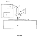
図1Aは、流体ジェット切断装置10の1つの例示的実施形態を示す。流体ジェット切断装置10は、高圧流体ジェットを作るためのポンプ12を含む。流体ジェット切断装置10によって切断されるべき繊維材料のためのコーティング組成物Cを貯蔵および放出するためのリザーバあるいは保持タンク14が、設けられる。第1の入口18および第2の入口20を有するノズル16が、高圧流体ジェットを作るためのポンプ12およびコーティング組成物Cを貯蔵するためのリザーバ14と流通する。ノズル16の第1の入口18は、ポンプ12から加圧流体ジェットJを受け入れる。加圧流体ジェットJは、ポンプ12とノズル16との間を流通する高圧配管あるいは導管22を通して送出される。
FIG. 1A shows one exemplary embodiment of a fluid
ノズル16の第2の入口24は、流体ジェット切断装置10のコーティング組成物保持リザーバ14からコーティング組成物Cを受け入れる。保持リザーバ14は、配管あるいは導管28によってノズル16の第2の入口24に連結された出口26を有する。装置10のノズル16内で、流体ジェットJおよびコーティング組成物Cは、合流して、ノズル16の出口30を通して繊維材料の表面の方向に放出される。
The
流体ジェット切断装置は、また、装置10によって切断されるべき繊維材料FMに対するノズル16の移動を制御するためのコントローラ32を含む。
The fluid jet cutting device also includes a
キャッチタンク34は、切断されるべき繊維材料FMの下方に配置される。流体ジェットが、繊維材料FMを切り離すとき、ジェットは、切断流体が収集されるタンク34中に流れ続け、選択的に流体のエネルギーがタンクの中の水Wによって吸収される。
The
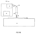
図1Bは、流体ジェット切断装置60の他の例示的実施形態を示す。流体ジェット切断装置60は、高圧流体ジェットを作るためのポンプ62を含む。図1Bの例示的実施形態によれば、コーティング組成物は、切断流体中にあらかじめ入れられるのがよい。従って、流体ジェット切断装置60によって切断されるべき繊維材料のためのコーティング組成物Cを貯蔵し且つ放出するための別々のリザーバあるいは保持タンクが必要とされない。入口66および出口68を有するノズル64は、高圧流体ジェットを作るためのポンプ62と流通する。ノズル64の入口66は、ポンプ62から加圧流体ジェットJを受け入れる。加圧流体ジェットJは、ポンプ62とノズル64との間を流通する高圧配管あるいは導管70を通して送出される。合流の切断流体およびコーティング組成物を含有する流体ジェットJが、ノズル64の出口68を通して繊維材料の表面の方向に放出される。
FIG. 1B shows another exemplary embodiment of a fluid jet cutting device 60. The fluid jet cutting device 60 includes a
流体ジェット切断装置は、また、装置60によって切断されるべき繊維材料FMに対してノズル64の移動を制御するためのコントローラ72を含む。キャッチタンク74は、切断されるべき繊維材料FMの下方に配置される。流体ジェットが、繊維材料FMを切り離すとき、ジェットは、切断流体が収集されるタンク75中に流れ続ける。ある実施形態では、流体ジェットのエネルギーは、タンクの中の水Wによって吸収される。
The fluid jet cutting device also includes a
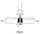
図2Aは、流体ジェットJがノズルの出口から放出される前の流体ジェット切断装置のノズル40の下方に配置された繊維材料マットMを示す。図2Bは、流体ジェット流Jがノズル40の出口42から放出され、切断経路Pに沿って繊維材料マットMに接触しているときの、図2Aの繊維材料マットMを示す。図2Cは、ノズル40から放出された流体ジェット流Jによって、全体の厚さを通して切断され、それによって2つの別々の繊維材料マットFM1、FM2を形成する、繊維材料マットMを示す。
FIG. 2A shows the fiber material mat M positioned below the
流体ジェット流Jが切断経路Pに沿って繊維材料マットMを切り離すとき、コーティング組成物、すなわちポリマーコーティング材料が、FM1の面50およびFM2の面52の少なくとも一部分上に同時に付着する。ある実施形態によれば、コーティング組成物Cのほぼ均一なコーティングは、繊維マットFM1の面50、FM2の面52のそれぞれ全領域に沿って付着する。繊維材料マットFMが2つの別々のマットFM1、FM2に分離された後、2つのマットは、無機繊維材料マットを乾燥する在来の方法によって乾燥される。マット乾燥工程中、面50、52上に付着したコーティング組成物Cは、マットFM1、FM2の露出された縁面にシールを提供する。切断マットの面50、52上の密封コーティングの形成により、通常、無機繊維材料のダイカットあるいはスタンピングと関連する、飛散粒子塵の可能性を実質的に除去する。
When the fluid jet stream J cuts the fiber material mat M along the cutting path P, the coating composition, ie the polymer coating material, is deposited simultaneously on at least a portion of the
流体ジェット切断方法によって切断された繊維取付けマットによってハウジング内に取付けられた脆弱触媒支持構造を有する排気ガス処理装置をも、開示する。取付けマットは、ディーゼル粒子トラップなどのような、いかなる脆弱構造をも取付けあるいは支持するために用いることができる。ディーゼル粒子トラップは、耐熱材料によってハウジング内に取付けられた1つ以上の多孔性の管状あるいは蜂の巣状構造(しかしながら、一端で閉じたチャネルを有する)を含む。粒子は、高温バーンアウト処理によって再生されるまで、排気ガスから多孔性構造中に収集される。用語「脆弱触媒支持構造」は、本質的に脆くあるいは壊れやすく、且つここに記載するような支持要素から利益を得るであろう、金属あるいはセラミックモノリスなどのような構造を意味し、且つ含むことを意図する。排気ガスを処理するための装置の1つの例示的形態は、触媒変換器である。触媒変換器は、一般的に管状ハウジングを含む。ハウジングは、一端に入口を、反対側の端に出口を含む。入口および出口は、一端および反対側の端の外側端に適当に形成され、内燃エンジンの排気システムの中の導管に固定されるのがよい。装置は、取付けマットによってハウジング内に支持され且つ制限される脆弱触媒支持構造を収容する。触媒支持体は、一端のその入口端面から反対側の端のその出口端面まで軸線方向に延びる複数のガス浸透通路を含む。触媒支持体は、既知の方法および形態で、適当な耐火金属あるいはセラミック材料から構成されるのがよい。 Also disclosed is an exhaust gas treatment device having a fragile catalyst support structure mounted within a housing by a fiber mounting mat cut by a fluid jet cutting method. The mounting mat can be used to mount or support any fragile structure, such as a diesel particle trap. Diesel particle traps include one or more porous tubular or honeycomb structures (however, having a closed channel at one end) attached within a housing by a refractory material. The particles are collected from the exhaust gas into the porous structure until regenerated by a high temperature burnout process. The term “brittle catalyst support structure” means and includes structures such as metals or ceramic monoliths that are inherently brittle or fragile and would benefit from support elements as described herein. Intended. One exemplary form of an apparatus for treating exhaust gas is a catalytic converter. A catalytic converter generally includes a tubular housing. The housing includes an inlet at one end and an outlet at the opposite end. The inlet and outlet are suitably formed at one end and the outer end of the opposite end and secured to a conduit in the exhaust system of the internal combustion engine. The apparatus houses a brittle catalyst support structure that is supported and limited within the housing by a mounting mat. The catalyst support includes a plurality of gas permeation passages extending axially from its inlet end face at one end to its outlet end face at the opposite end. The catalyst support may be constructed from a suitable refractory metal or ceramic material in a known manner and form.
触媒支持体は、距離あるいはギャップによってハウジングから間隔を隔てられ、距離あるいはギャップは、例えば、触媒変換器あるいはディーゼル粒子トラップなど利用する装置のタイプおよび設計により変化する。このギャップには、触媒支持体に弾性支持体を提供するために取付けマットが充填される。マットは、外部環境に断熱と、触媒支持構造に機械的支持の両方を提供し、脆弱構造を機械的衝撃から保護する。 The catalyst support is spaced from the housing by a distance or gap, which varies depending on the type and design of the equipment utilized, such as, for example, a catalyst converter or a diesel particle trap. This gap is filled with a mounting mat to provide an elastic support for the catalyst support. The mat provides both thermal insulation for the external environment and mechanical support for the catalyst support structure, protecting the fragile structure from mechanical shock.
以下の例示的実施例は、流体ジェット装置および流体ジェット切断方法を更に説明するために記載される。流体ジェット装置および切断方法は、いかなる方法でも例示的実施例に限定されるべきではないことに留意すべきである。 The following exemplary embodiments are described to further illustrate the fluid jet apparatus and fluid jet cutting method. It should be noted that the fluid jet device and cutting method should not be limited to the exemplary embodiments in any way.
(実施例1)
CC−MAX8HPの名称でユニフラックス社によって販売されている繊維材料マットのサンプルを流体ジェット装置および方法を用いて切断した。CC−MAX8HP繊維マットは、ガラス質のアルミノシリケート繊維の非膨張マットである。この繊維マットは、ニードルパンチされ、いかなるバインダー材料をも含有しない。CC−MAX8HP繊維マットは、セラミックおよび金属触媒支持基板を自動車の排気ガス処理装置の中に取付けるために用いられる。CC−MAX8HPは、自動車の排気ガス処理装置ハウジングと触媒支持基板との間の空間中に配置されて、触媒支持基板に熱的および機械的衝撃抵抗を提供する。
Example 1
A sample of a fiber mat sold by Uniflux Corporation under the name CC-MAX8HP was cut using a fluid jet apparatus and method. The CC-MAX8HP fiber mat is a non-intumescent mat of vitreous aluminosilicate fibers. This fiber mat is needle punched and does not contain any binder material. The CC-MAX8HP fiber mat is used to mount ceramic and metal catalyst support substrates in automobile exhaust gas treatment equipment. The CC-MAX8HP is disposed in the space between the automobile exhaust gas treatment device housing and the catalyst support substrate to provide thermal and mechanical impact resistance to the catalyst support substrate.
繊維マットの12×12インチサンプルを、流体ジェット切断装置の切断領域内に配置した。入口の水を60,000psi(4.1×10⁸Pa)の圧力まで加圧して高圧水ジェットを作った。流体ジェットのノズルを、切断されるべき繊維マットの上方に位置決めした。アクリルラテックスを収容するコーティング組成物保持リザーバを、装置のノズルと流通させて配置した。アクリルラテックスを、導管によって装置のノズルに送出し、加圧水と合流させた。一旦、ノズルを繊維マットの上方に適当に位置決めしたならば、水およびラテックス材料を含有する流体ジェットを装置のノズルから放出し、且つ繊維マットの表面上に差し向けた。流体ジェットの移動を、所定の切断経路に沿って導いて、切断繊維マットの実質的に正方形ピースを作った。 A 12 × 12 inch sample of fiber mat was placed in the cutting area of the fluid jet cutting device. The inlet water was pressurized to a pressure of 60,000 psi (4.1 × 10 8 Pa) to create a high pressure water jet. The nozzle of the fluid jet was positioned above the fiber mat to be cut. A coating composition holding reservoir containing acrylic latex was placed in communication with the nozzle of the apparatus. Acrylic latex was delivered by conduit to the apparatus nozzle and merged with pressurized water. Once the nozzle was properly positioned above the fiber mat, a fluid jet containing water and latex material was discharged from the nozzle of the device and directed onto the surface of the fiber mat. The movement of the fluid jet was guided along a predetermined cutting path to create a substantially square piece of cut fiber mat.
切断繊維マットピースを、流体ジェット切断装置から取り出し、乾燥させて、切断工程で吸収された水を除去した。繊維マットの切断および乾燥したサンプルを、流体ジェット切断工程による、露出された縁面上のコーティングの付着を分析した。切断工程によって露出された繊維面上に付着したコーティング組成物の量を分析するために、乾燥マットサンプルの重量を最初に得た。次いで、乾燥マットサンプルを約700℃の温度まで約2時間加熱した。マットサンプル上に付着した有機コーティング組成物を、マットの加熱中、焼き払った。マットサンプルの加熱に続いて、マットサンプルを再計量した。流体ジェット切断工程中、マットサンプルの露出した縁面上に付着したコーティングの量を、サンプルを700℃で2時間加熱する前後でのマットサンプルの重量間の差として計算した。 The cut fiber mat piece was removed from the fluid jet cutting device and dried to remove the water absorbed in the cutting process. Fiber mat cuts and dried samples were analyzed for coating adhesion on exposed edges by a fluid jet cutting process. To analyze the amount of coating composition deposited on the fiber surface exposed by the cutting process, the weight of the dry mat sample was first obtained. The dried mat sample was then heated to a temperature of about 700 ° C. for about 2 hours. The organic coating composition deposited on the mat sample was burned off while the mat was heated. Following heating of the mat sample, the mat sample was reweighed. During the fluid jet cutting process, the amount of coating deposited on the exposed edge of the mat sample was calculated as the difference between the weight of the mat sample before and after heating the sample at 700 ° C. for 2 hours.
(実施例2〜4)
繊維基板の縁面上の有機コーティング組成物の付着の効果を分析した。
(Examples 2 to 4)
The effect of adhesion of the organic coating composition on the edge of the fiber substrate was analyzed.
実施例2〜4の各々は、CC−MAX8HPの名称でユニフラックス社によって販売されている繊維材料マットを含んだ。CC−MAX8HP繊維マットは、ガラス質のアルミノシリケート繊維の非膨張マットである。この繊維マットは、ニードルパンチされ、いかなる有機バインダー材料も含有しない。 Each of Examples 2-4 included a fiber material mat sold by Uniflux Corporation under the name CC-MAX8HP. The CC-MAX8HP fiber mat is a non-intumescent mat of vitreous aluminosilicate fibers. This fiber mat is needle punched and does not contain any organic binder material.
比較例2をダイカット工程によって切断し、切断縁面に有機物コーティング組成物は付着しなかった。比較例3も、また、ダイカット工程によって切断した。付加的なおよび別々のステップで、実施例C3の繊維マットの切断縁面を有機コーティング組成物でスプレーコーティングした。実施例4を、流体ジェット切断方法によって切断し、それによって加圧流体流が繊維マットを切断し、同時に有機コーティング組成物が切断縁面に付着した。各切断繊維サンプルの強さを評価した。各繊維マットは、強さの程度に応じて、1乃至5の数字を割り当て、5が最強を示す。結果を以下の表1に示す。 Comparative Example 2 was cut by a die cutting process, and the organic coating composition did not adhere to the cut edge surface. Comparative Example 3 was also cut by a die cutting process. In an additional and separate step, the cut edge of the fiber mat of Example C3 was spray coated with the organic coating composition. Example 4 was cut by a fluid jet cutting method whereby a pressurized fluid stream cut the fiber mat while the organic coating composition adhered to the cutting edge. The strength of each cut fiber sample was evaluated. Each fiber mat is assigned a number from 1 to 5 according to the degree of strength, with 5 being the strongest. The results are shown in Table 1 below.

比較例2は、あまり強くなかった。繊維マットの切断縁面上に有機コーティングをスプレーコーティングした比較例3は、最初の強さから増大を示した。しかしながら、スプレーされた有機コーティングは、切断縁面から容易に剥がれたことに留意しなければならない。実施例4は、3つの試験繊維サンプルの最高の強さを示した。 Comparative Example 2 was not very strong. Comparative Example 3 spray coated with an organic coating on the cut edge of the fiber mat showed an increase from the initial strength. However, it should be noted that the sprayed organic coating easily peeled off the cut edge. Example 4 showed the highest strength of the three test fiber samples.
(実施例5−8)
飛散繊維の発生時、繊維基板の縁面上に有機コーティング組成物を付着させることの影響を分析した。触媒支持基板に繊維マットを巻くことによって飛散繊維の発生を評価した。基板を包囲環境内で巻き、発生した飛散繊維を標準空気監視フィルタ媒体上に収集した。飛散繊維を収集したフィルタ媒体を、NIOSH分析法マニュアルに記載された7400(b)計上方法に従って、測定した。
(Example 5-8)
The influence of depositing the organic coating composition on the edge surface of the fiber substrate was analyzed when the scattered fibers were generated. The generation of scattered fibers was evaluated by winding a fiber mat around the catalyst support substrate. The substrate was wound in an ambient environment and the generated scattered fibers were collected on a standard air monitoring filter medium. The filter media on which the scattered fibers were collected was measured according to the 7400 (b) counting method described in the NIOSH analysis method manual.
実施例C5および6は、CC−MAX8HPの名称でユニフラックス社によって販売されている繊維材料マットを含んだ。CC−MAX8HP繊維マットは、ガラス質のアルミノシリケート繊維の非膨張マットである。この繊維マットは、ニードルパンチされ、いかなる有機バインダー材料も含有しない。 Examples C5 and 6 included a fiber material mat sold by Uniflux Corporation under the name CC-MAX8HP. The CC-MAX8HP fiber mat is a non-intumescent mat of vitreous aluminosilicate fibers. This fiber mat is needle punched and does not contain any organic binder material.
実施例C7および8は、CC−MAX4HPの名称でユニフラックス社によって販売されている繊維材料マットを含んだ。CC−MAX4HP繊維マットは、ガラス質のアルミノシリケート繊維の非膨張マットである。この繊維マットをバインダーで処理した。実施例C7および8の繊維マットは、ほぼ等しい量のバインダーを含有する。CC−MAX4HP繊維マットは、また、マット構造の取り扱いやすさを増すための支持層を備える。 Examples C7 and 8 included a fiber material mat sold by Uniflux Corporation under the name CC-MAX4HP. The CC-MAX4HP fiber mat is a non-expandable mat of vitreous aluminosilicate fibers. This fiber mat was treated with a binder. The fiber mats of Examples C7 and 8 contain approximately equal amounts of binder. The CC-MAX4HP fiber mat also includes a support layer to increase the handleability of the mat structure.
比較例C5およびC7を、ダイカット工程によって切断し、切断縁面に有機コーティング組成物は付着しなかった。実施例6および8を流体ジェット切断方法によって切断し、それによって加圧流体流が繊維マットを切断し、同時に有機コーティング組成物が切断縁面上に付着した。切断工程中の飛散繊維の発生を評価した。結果を以下の表2に示す。 Comparative Examples C5 and C7 were cut by a die cutting process, and the organic coating composition did not adhere to the cut edge surface. Examples 6 and 8 were cut by a fluid jet cutting method whereby a pressurized fluid stream cut the fiber mat while the organic coating composition was deposited on the cutting edge. The generation of scattered fibers during the cutting process was evaluated. The results are shown in Table 2 below.
表2が示すように、従来のダイカット技術での切断繊維基板(比較例C5およびC7)は、大量の飛散繊維の発生をもたらす。一方、コーティングが切断縁面に同時に付着する流体ジェット切断方法によって切断した実施例6の繊維マットは、飛散繊維の発生を、ダイカットの比較例C5によって発生した繊維の25%未満に減じる。 As Table 2 shows, the cut fiber substrate (Comparative Examples C5 and C7) with the conventional die-cutting technique results in the generation of a large amount of scattered fibers. On the other hand, the fiber mat of Example 6 cut by the fluid jet cutting method where the coating simultaneously adheres to the cutting edge reduces the generation of scattered fibers to less than 25% of the fibers generated by the die cut Comparative Example C5.
実施例C7および8は、繊維を所定の位置に保持するためにバインダーで処理された繊維マットであるので、放出繊維は予期されないであろう。しかしながら、実施例8の繊維マットを流体ジェット切断することにより、飛散繊維の発生を、実施例C7の繊維マットをダイカットすることによって発生した飛散繊維の33%に減少させる。実施例C7および8の飛散繊維発生試験の結果は、さもなければ繊維の放出を予期できないであろうバインダー含有マット上にコーティングの縁処理を付着させることの利点を示す。 Since Examples C7 and 8 are fiber mats treated with a binder to hold the fibers in place, release fibers would not be expected. However, the fiber mat of Example 8 is fluid jet cut to reduce the generation of scattered fibers to 33% of the scattered fibers generated by die cutting the fiber mat of Example C7. The results of the scattered fiber generation test of Examples C7 and 8 show the benefit of depositing the coating edge treatment on a binder-containing mat that would otherwise have no expectation of fiber release.
流体ジェット切断方法の精度を、切断繊維マットサンプルを分析することによって評価した。CC−MAX8HPの名称でユニフラックス社によって販売されているマットからなる100個の繊維マットサンプルを流体ジェット切断装置および方法を用いて切断した。取付けマットを、噛み合いタブおよびスロット配置を有するマットを提供する方法で、切断した。各切断繊維マット上のタブおよびスロットの幅を測定した。切断繊維マットの測定は、タブの幅とスロットの幅との間の変化が、0.5mm以下であったことを示す。これらの結果は、流体ジェット切断方法が、少なくとも繊維マットの従来のダイカットによって達成できる精度と同じ精度である、正確な、きれいな切断部を有する繊維マット構造を提供することを示す。従って、減じられた飛散繊維の発生の利点が加えられて、流体ジェット切断方法を用いて、正確な切断を達成して、所定の用途の公差に適合させることができる。 The accuracy of the fluid jet cutting method was evaluated by analyzing cut fiber mat samples. 100 fiber mat samples consisting of a mat sold by Uniflux under the name CC-MAX8HP were cut using a fluid jet cutting apparatus and method. The mounting mat was cut in a manner that provided a mat with a mating tab and slot arrangement. The width of the tabs and slots on each cut fiber mat was measured. Measurement of the cut fiber mat indicates that the change between the tab width and the slot width was 0.5 mm or less. These results show that the fluid jet cutting method provides a fiber mat structure with an accurate, clean cut that is at least as accurate as can be achieved by conventional die cutting of the fiber mat. Thus, the advantage of reduced spatter fiber generation can be added, and fluid jet cutting methods can be used to achieve accurate cutting and to meet the tolerances of a given application.
上述の実施例によれば、流体ジェット切断方法を用いて、アルミノシリケート繊維からなる繊維材料物品を切断した。しかしながら、流体ジェット切断方法を用いて、限定でなく、アルミナ繊維、アルミナ−シリカ−マグネシア繊維、カルシア−マグネシア−シリカ繊維、マグネシア−シリカ繊維、カルシア−アルミナ繊維、Eガラス繊維、Sガラス繊維、ミネラルウール繊維、これらの組み合わせなどを含む無機繊維のいかなるタイプをも含有する繊維材料物品を切断することができることに留意すべきである。 According to the above-described embodiment, a fiber material article made of aluminosilicate fibers was cut using a fluid jet cutting method. However, using a fluid jet cutting method, it is not limited to alumina fiber, alumina-silica-magnesia fiber, calcia-magnesia-silica fiber, magnesia-silica fiber, calcia-alumina fiber, E glass fiber, S glass fiber, mineral It should be noted that fiber material articles containing any type of inorganic fibers including wool fibers, combinations thereof, etc. can be cut.
本方法は、また、繊維材料物品を切断し、同時に密封コーティング以外の所望の薬品あるいは材料を、流体ジェット流によって切断されるべき繊維材料物品の少なくとも一部分上に付着させるために利用することができる。例示として、および限定でなく、着色料あるいは染料のような材料を、流体ジェット流に含まれ、物品が流体ジェット流によって切断されるとき、繊維材料物品の一部分上に同時に付着させてもよい。他の実施形態によれば、流体ジェット切断方法によって接着剤を切断縁面に付着させてもよい。着色料あるいは染料の混和により、繊維材料物品のその後の識別が可能になる。 The method can also be utilized to cut a fibrous material article while simultaneously depositing a desired chemical or material other than a sealing coating on at least a portion of the fibrous material article to be cut by a fluid jet stream. . By way of illustration and not limitation, materials such as colorants or dyes may be included in the fluid jet stream and deposited simultaneously on a portion of the fibrous material article when the article is cut by the fluid jet stream. According to other embodiments, the adhesive may be applied to the cutting edge by a fluid jet cutting method. The incorporation of colorants or dyes allows subsequent identification of the fiber material article.
流体ジェット切断方法を、ある例示的実施形態に関連して上述してきたが、他の同様の実施形態を用いてもよいし、あるいは記載された実施形態から逸脱することなしに本方法の同じ機能を果たすために、変形および追加を記載された実施形態に行ってもよい。更に、様々な実施形態を結合して、所望の特性を提供することができるので、開示された全ての実施形態は必ずしも選択的ではない。本発明の精神および範囲から逸脱することなしに、当業者によって変形をなすことができる。従って、本方法は、いかなる単一の実施形態に限定されるべきでなく、添付した特許請求の範囲の記載による外延および範囲内に解釈されるべきである。 Although a fluid jet cutting method has been described above with respect to certain exemplary embodiments, other similar embodiments may be used, or the same functionality of the method without departing from the described embodiments. Variations and additions may be made to the described embodiments to accomplish this. Moreover, all disclosed embodiments are not necessarily selective, as various embodiments can be combined to provide desired properties. Modifications can be made by those skilled in the art without departing from the spirit and scope of the invention. Thus, the method should not be limited to any single embodiment, but should be construed within the extension and scope of the appended claims.
Claims (21)
前記流体ジェットは、キャリア流体および前記繊維材料上に付着させるための所望の薬品を含有し、
前記繊維材料を前記流体ジェットで切断するステップを含む、
ことを特徴とする流体ジェット切断方法。 Contacting the fibrous material with a pressurized fluid jet,
The fluid jet contains a carrier fluid and a desired chemical for deposition on the fiber material;
Cutting the fibrous material with the fluid jet,
A fluid jet cutting method.
前記流体ジェットは、キャリア流体および前記繊維材料のためのコーティング組成物を含有し、
前記繊維材料を前記流体ジェットで切断するステップと、
前記コーティング組成物を前記繊維材料の少なくとも一部分上に付着させるステップと、を含む、
請求項3に記載の流体ジェット切断方法。 Contacting the fibrous material with a pressurized fluid jet,
The fluid jet contains a carrier fluid and a coating composition for the fiber material;
Cutting the fibrous material with the fluid jet;
Depositing the coating composition on at least a portion of the fibrous material.
The fluid jet cutting method according to claim 3.
前記ハウジング内に弾性的に取付けられた脆弱触媒支持構造と、
請求項15に記載の流体ジェット切断無機繊維取付けマットと、を含み、
前記取付けマットは、前記脆弱触媒支持構造を前記ハウジング内に弾性的に保持するために、前記ハウジングと前記脆弱触媒支持構造との間のギャップの中に配置され、
前記取付けマットは、流体ジェット切断縁面の少なくとも一部分に付着したコーティングを含む、
ことを特徴とする排気ガス処理装置。 A housing;
A brittle catalyst support structure elastically mounted in the housing;
A fluid jet cutting inorganic fiber mounting mat according to claim 15;
The mounting mat is disposed in a gap between the housing and the fragile catalyst support structure to resiliently hold the fragile catalyst support structure within the housing;
The mounting mat includes a coating attached to at least a portion of the fluid jet cutting edge.
An exhaust gas treatment apparatus characterized by that.
加圧流体ジェットを作るためのポンプと、
前記繊維材料のための切断流体を収容するリザーバと、を含み、
前記切断流体は、コーティング組成物を選択的に有し、
前記切断流体を受け入れるための入口および前記切断流体を繊維基板上に放出するための出口を有するノズルと、を含む、
ことを特徴とする装置。 An apparatus for use in the fluid jet cutting method according to any one of claims 1 to 12,
A pump for making a pressurized fluid jet;
A reservoir containing a cutting fluid for the fiber material,
The cutting fluid selectively comprises a coating composition;
A nozzle having an inlet for receiving the cutting fluid and an outlet for discharging the cutting fluid onto a fiber substrate.
A device characterized by that.
前記切断流体の加圧流体ジェットを受け入れるための第1の入口と、前記コーティング組成物を受け入れるための第2の入口と、前記切断流体およびコーティング組成物を合流させるための容積と、を有するノズルと、
前記流体ジェットおよびコーティング組成物を放出する出口と、を含む、
請求項20に記載の装置。 A reservoir for separately containing the cutting fluid and the coating composition;
A nozzle having a first inlet for receiving a pressurized fluid jet of the cutting fluid, a second inlet for receiving the coating composition, and a volume for joining the cutting fluid and coating composition When,
An outlet for discharging the fluid jet and coating composition.
The apparatus of claim 20.
Applications Claiming Priority (2)
| Application Number | Priority Date | Filing Date | Title |
|---|---|---|---|
| US69023405P | 2005-06-14 | 2005-06-14 | |
| PCT/US2006/022981 WO2006138307A2 (en) | 2005-06-14 | 2006-06-14 | Fluid jet cutting process |
Related Child Applications (1)
| Application Number | Title | Priority Date | Filing Date |
|---|---|---|---|
| JP2012222343A Division JP2013040612A (en) | 2005-06-14 | 2012-10-04 | Fluid jet cutting process |
Publications (1)
| Publication Number | Publication Date |
|---|---|
| JP2008546918A true JP2008546918A (en) | 2008-12-25 |
Family
ID=37571068
Family Applications (4)
| Application Number | Title | Priority Date | Filing Date |
|---|---|---|---|
| JP2008517015A Pending JP2008546918A (en) | 2005-06-14 | 2006-06-14 | Fluid jet cutting method |
| JP2012222343A Pending JP2013040612A (en) | 2005-06-14 | 2012-10-04 | Fluid jet cutting process |
| JP2015112261A Pending JP2015206367A (en) | 2005-06-14 | 2015-06-02 | Fluid jet cutting process |
| JP2017097370A Active JP6360590B2 (en) | 2005-06-14 | 2017-05-16 | Fluid jet cutting method |
Family Applications After (3)
| Application Number | Title | Priority Date | Filing Date |
|---|---|---|---|
| JP2012222343A Pending JP2013040612A (en) | 2005-06-14 | 2012-10-04 | Fluid jet cutting process |
| JP2015112261A Pending JP2015206367A (en) | 2005-06-14 | 2015-06-02 | Fluid jet cutting process |
| JP2017097370A Active JP6360590B2 (en) | 2005-06-14 | 2017-05-16 | Fluid jet cutting method |
Country Status (12)
| Country | Link |
|---|---|
| US (1) | US7829036B2 (en) |
| EP (2) | EP3290171A1 (en) |
| JP (4) | JP2008546918A (en) |
| KR (1) | KR101370814B1 (en) |
| CN (1) | CN101316688B (en) |
| BR (1) | BRPI0612300A2 (en) |
| CA (1) | CA2635222C (en) |
| DE (1) | DE06773032T1 (en) |
| ES (1) | ES2304333T1 (en) |
| MX (1) | MX2007015983A (en) |
| WO (1) | WO2006138307A2 (en) |
| ZA (1) | ZA200800286B (en) |
Cited By (3)
| Publication number | Priority date | Publication date | Assignee | Title |
|---|---|---|---|---|
| JP2013040612A (en) * | 2005-06-14 | 2013-02-28 | Unifrax I Llc | Fluid jet cutting process |
| JP2015107542A (en) * | 2013-12-05 | 2015-06-11 | イビデン株式会社 | Method for cutting sheet-like member, mat, method for production of exhaust gas-purifying device, and exhaust gas-purifying device |
| KR101803008B1 (en) | 2011-05-04 | 2017-11-30 | 삼성디스플레이 주식회사 | Substrate processing apparatus and method of operating the same |
Families Citing this family (15)
| Publication number | Priority date | Publication date | Assignee | Title |
|---|---|---|---|---|
| US8517083B2 (en) * | 2007-12-14 | 2013-08-27 | Refractory Specialties, Incorporated | System, apparatus and method for manufacturing metal ingots |
| EP2177662B1 (en) * | 2008-10-16 | 2011-01-05 | 3con Anlagebau GmbH | Method and device for cutting knitted or woven goods and corresponding compound materials |
| US10422333B2 (en) * | 2010-09-13 | 2019-09-24 | Quantum Servo Pumping Technologies Pty Ltd | Ultra high pressure pump |
| US20130126168A1 (en) * | 2011-11-21 | 2013-05-23 | Express Energy Services Operating Lp | Rotary Fluid Jet Cutter |
| CN102672626B (en) * | 2012-05-28 | 2014-04-09 | 江苏大学 | Ultrahigh pressure water jet velocity optimal control method extracted based on voice characteristics |
| CN103397451A (en) * | 2013-07-30 | 2013-11-20 | 苏州豪建纺织有限公司 | Quick cloth breaking structure of weaving machine |
| DE102015118610A1 (en) * | 2015-10-30 | 2017-05-04 | Nienstedt Gmbh | Device for dividing food |
| JP7124272B2 (en) * | 2017-07-21 | 2022-08-24 | 株式会社三洋物産 | game machine |
| JP7124274B2 (en) * | 2017-07-21 | 2022-08-24 | 株式会社三洋物産 | game machine |
| JP7124271B2 (en) * | 2017-07-21 | 2022-08-24 | 株式会社三洋物産 | game machine |
| JP7124275B2 (en) * | 2017-07-21 | 2022-08-24 | 株式会社三洋物産 | game machine |
| CN108677515A (en) * | 2018-04-24 | 2018-10-19 | 深圳市金吉峰科技有限公司 | A kind of hot wind knife cuts cotton fibre technology |
| CN110948563B (en) * | 2019-12-09 | 2021-08-27 | 台州市黄岩金多塑业有限公司 | PVC foaming board high efficiency cutting dust collecting equipment |
| CN111633723A (en) * | 2020-06-11 | 2020-09-08 | 合肥市兴烨包装材料有限公司 | Cotton cutting device that uses of high strength pearl |
| CN115074984B (en) * | 2022-07-07 | 2023-11-14 | 湖北鱼鹤制衣有限公司 | Cloth cutting device |
Citations (4)
| Publication number | Priority date | Publication date | Assignee | Title |
|---|---|---|---|---|
| JPH06146872A (en) * | 1992-10-30 | 1994-05-27 | Asahi Glass Co Ltd | Heat-resistant seal member and seal structure |
| JP2000096355A (en) * | 1998-09-18 | 2000-04-04 | Mitsubishi Rayon Co Ltd | Production of staple fiber |
| US6103049A (en) * | 1994-05-31 | 2000-08-15 | Johns Manville International, Inc. | Method and apparatus for cutting, sealing and encapsulated fibrous products |
| JP2002539924A (en) * | 1999-03-24 | 2002-11-26 | フロー インターナショナル コーポレイション | Fluid jet forming method and apparatus |
Family Cites Families (20)
| Publication number | Priority date | Publication date | Assignee | Title |
|---|---|---|---|---|
| US3524367A (en) * | 1968-05-31 | 1970-08-18 | Norman C Franz | High velocity liquid jet |
| US3532014A (en) * | 1968-10-01 | 1970-10-06 | Norman C Franz | Method for the high velocity liquid jet cutting of soft materials |
| JPS569472A (en) * | 1979-07-03 | 1981-01-30 | Nat Jutaku Kenzai | Cutting of fibrous heat insulating material |
| DE4341870B4 (en) | 1992-12-08 | 2008-03-13 | Flow International Corp., Kent | Ultra high-pressure flat-jet nozzle |
| US5961053A (en) | 1994-02-18 | 1999-10-05 | Flow International Corporation | Ultrahigh-pressure fan jet nozzle |
| JP3007240B2 (en) * | 1993-04-02 | 2000-02-07 | 東芝モノフラックス株式会社 | Inorganic fiber molding |
| JPH06294071A (en) * | 1993-04-08 | 1994-10-21 | Chubu Kogyo Kk | Prevention of skin stimulation and scattering of inorganic fiber |
| US6299510B1 (en) | 1998-04-28 | 2001-10-09 | Flow International Corporation | Abrasive removal system for use with high-pressure fluid-jet cutting device |
| JP2002066331A (en) * | 2000-08-25 | 2002-03-05 | Nichias Corp | Catalyst carrier holding member, its production process and catalytic converter |
| US7524546B2 (en) | 2000-12-28 | 2009-04-28 | 3M Innovative Properties Company | Thermal insulating material and pollution control device using the same |
| DE10113475A1 (en) * | 2001-03-13 | 2002-09-19 | D Wuestenberg Fachbereich Masc | Cutting fluid for maintained coherence passes fluid through evacuated or under pressurized space en route to workpiece held with stream in closed or evacuated container |
| JP4993816B2 (en) * | 2001-05-25 | 2012-08-08 | イビデン株式会社 | Alumina-silica fiber and method for producing the same, holding seal material for catalytic converter |
| US6766216B2 (en) | 2001-08-27 | 2004-07-20 | Flow International Corporation | Method and system for automated software control of waterjet orientation parameters |
| US7464630B2 (en) | 2001-08-27 | 2008-12-16 | Flow International Corporation | Apparatus for generating and manipulating a high-pressure fluid jet |
| JP4221179B2 (en) * | 2002-01-22 | 2009-02-12 | イビデン株式会社 | Holding sealing material |
| US6688947B2 (en) | 2002-02-05 | 2004-02-10 | The Johns Hopkins University | Porous, lubricated nozzle for abrasive fluid suspension jet |
| JP4452030B2 (en) * | 2002-04-03 | 2010-04-21 | 新日本製鐵株式会社 | Refractory reinforced with rod-shaped molded body made of inorganic fiber and method for producing the same |
| US6835413B2 (en) | 2002-09-17 | 2004-12-28 | Owens Corning Fiberglas Technology, Inc. | Surface coating for insulation pack |
| DE10257113A1 (en) * | 2002-12-05 | 2004-06-24 | Emitec Gesellschaft Für Emissionstechnologie Mbh | Particle trap with coated fiber layer |
| JP2008546918A (en) * | 2005-06-14 | 2008-12-25 | ユニフラックス I リミテッド ライアビリティ カンパニー | Fluid jet cutting method |
-
2006
- 2006-06-14 JP JP2008517015A patent/JP2008546918A/en active Pending
- 2006-06-14 DE DE2006773032 patent/DE06773032T1/en active Pending
- 2006-06-14 US US11/452,802 patent/US7829036B2/en active Active
- 2006-06-14 EP EP17158745.4A patent/EP3290171A1/en not_active Withdrawn
- 2006-06-14 BR BRPI0612300-7A patent/BRPI0612300A2/en not_active Application Discontinuation
- 2006-06-14 CN CN2006800294901A patent/CN101316688B/en active Active
- 2006-06-14 ES ES06773032T patent/ES2304333T1/en active Pending
- 2006-06-14 CA CA 2635222 patent/CA2635222C/en not_active Expired - Fee Related
- 2006-06-14 WO PCT/US2006/022981 patent/WO2006138307A2/en active Application Filing
- 2006-06-14 KR KR1020087000840A patent/KR101370814B1/en active IP Right Grant
- 2006-06-14 MX MX2007015983A patent/MX2007015983A/en active IP Right Grant
- 2006-06-14 EP EP06773032A patent/EP1899123A4/en not_active Ceased
-
2008
- 2008-01-09 ZA ZA200800286A patent/ZA200800286B/en unknown
-
2012
- 2012-10-04 JP JP2012222343A patent/JP2013040612A/en active Pending
-
2015
- 2015-06-02 JP JP2015112261A patent/JP2015206367A/en active Pending
-
2017
- 2017-05-16 JP JP2017097370A patent/JP6360590B2/en active Active
Patent Citations (4)
| Publication number | Priority date | Publication date | Assignee | Title |
|---|---|---|---|---|
| JPH06146872A (en) * | 1992-10-30 | 1994-05-27 | Asahi Glass Co Ltd | Heat-resistant seal member and seal structure |
| US6103049A (en) * | 1994-05-31 | 2000-08-15 | Johns Manville International, Inc. | Method and apparatus for cutting, sealing and encapsulated fibrous products |
| JP2000096355A (en) * | 1998-09-18 | 2000-04-04 | Mitsubishi Rayon Co Ltd | Production of staple fiber |
| JP2002539924A (en) * | 1999-03-24 | 2002-11-26 | フロー インターナショナル コーポレイション | Fluid jet forming method and apparatus |
Cited By (4)
| Publication number | Priority date | Publication date | Assignee | Title |
|---|---|---|---|---|
| JP2013040612A (en) * | 2005-06-14 | 2013-02-28 | Unifrax I Llc | Fluid jet cutting process |
| JP2015206367A (en) * | 2005-06-14 | 2015-11-19 | ユニフラックス ワン リミテッド ライアビリティ カンパニー | Fluid jet cutting process |
| KR101803008B1 (en) | 2011-05-04 | 2017-11-30 | 삼성디스플레이 주식회사 | Substrate processing apparatus and method of operating the same |
| JP2015107542A (en) * | 2013-12-05 | 2015-06-11 | イビデン株式会社 | Method for cutting sheet-like member, mat, method for production of exhaust gas-purifying device, and exhaust gas-purifying device |
Also Published As
| Publication number | Publication date |
|---|---|
| DE06773032T1 (en) | 2008-10-09 |
| EP3290171A1 (en) | 2018-03-07 |
| ES2304333T1 (en) | 2008-10-16 |
| JP2017141841A (en) | 2017-08-17 |
| ZA200800286B (en) | 2008-12-31 |
| JP2013040612A (en) | 2013-02-28 |
| WO2006138307A2 (en) | 2006-12-28 |
| EP1899123A4 (en) | 2011-08-17 |
| US20070006699A1 (en) | 2007-01-11 |
| US7829036B2 (en) | 2010-11-09 |
| BRPI0612300A2 (en) | 2010-11-03 |
| CA2635222C (en) | 2013-04-30 |
| CN101316688A (en) | 2008-12-03 |
| JP2015206367A (en) | 2015-11-19 |
| CA2635222A1 (en) | 2006-12-28 |
| KR101370814B1 (en) | 2014-03-07 |
| MX2007015983A (en) | 2008-03-07 |
| CN101316688B (en) | 2013-08-21 |
| JP6360590B2 (en) | 2018-07-18 |
| EP1899123A2 (en) | 2008-03-19 |
| KR20080034432A (en) | 2008-04-21 |
| WO2006138307A3 (en) | 2007-06-07 |
Similar Documents
| Publication | Publication Date | Title |
|---|---|---|
| JP6360590B2 (en) | Fluid jet cutting method | |
| JP6129814B2 (en) | Mounting mat provided with flexible edge protecting agent and exhaust gas treatment apparatus incorporating the mounting mat | |
| US8133443B2 (en) | Pollution control device and inorganic fiber sheet material with a fused edge | |
| EP1931862B1 (en) | Holding material for pollution control element and pollution control apparatus | |
| EP1772600B1 (en) | Holding sealer and exhaust gas processing device | |
| CN104941571B (en) | Adsorption catalyst and its preparation method and application and a kind of air cleaning unit and air purification method and its application | |
| KR20060128742A (en) | A supporting sealant and a method for the preparation thereof | |
| JP2005074243A (en) | Contamination controlling element-holding material and contamination controlling apparatus | |
| EP1848879A2 (en) | Pollution control element-mounting member and pollution control device | |
| JPH09201514A (en) | Catalyst converter and manufacture thereof | |
| EP2143902B1 (en) | Holding sealing material, exhaust gas purifying apparatus and method for manufacturing exhaust gas purifying apparatus | |
| JP2014034968A (en) | Method for manufacturing exhaust gas purification device and exhaust gas purification device |
Legal Events
| Date | Code | Title | Description |
|---|---|---|---|
| A131 | Notification of reasons for refusal |
Free format text: JAPANESE INTERMEDIATE CODE: A131 Effective date: 20101129 |
|
| A601 | Written request for extension of time |
Free format text: JAPANESE INTERMEDIATE CODE: A601 Effective date: 20110225 |
|
| A602 | Written permission of extension of time |
Free format text: JAPANESE INTERMEDIATE CODE: A602 Effective date: 20110304 |
|
| A521 | Request for written amendment filed |
Free format text: JAPANESE INTERMEDIATE CODE: A523 Effective date: 20110530 |
|
| A131 | Notification of reasons for refusal |
Free format text: JAPANESE INTERMEDIATE CODE: A131 Effective date: 20111031 |
|
| A521 | Request for written amendment filed |
Free format text: JAPANESE INTERMEDIATE CODE: A523 Effective date: 20120131 |
|
| A02 | Decision of refusal |
Free format text: JAPANESE INTERMEDIATE CODE: A02 Effective date: 20120604 |
|
| A601 | Written request for extension of time |
Free format text: JAPANESE INTERMEDIATE CODE: A601 Effective date: 20130228 |
|
| A602 | Written permission of extension of time |
Free format text: JAPANESE INTERMEDIATE CODE: A602 Effective date: 20130305 |
|
| A521 | Request for written amendment filed |
Free format text: JAPANESE INTERMEDIATE CODE: A523 Effective date: 20130603 |
|
| A601 | Written request for extension of time |
Free format text: JAPANESE INTERMEDIATE CODE: A601 Effective date: 20131007 |
|
| A602 | Written permission of extension of time |
Free format text: JAPANESE INTERMEDIATE CODE: A602 Effective date: 20131010 |
|
| A521 | Request for written amendment filed |
Free format text: JAPANESE INTERMEDIATE CODE: A523 Effective date: 20131107 |