【0001】
【発明の属する技術分野】
本発明は、汚染コントロール要素の保持材に関し、さらに詳しく述べると、触媒担体やフィルター要素のような汚染コントロール要素の保持材に関する。本発明は特に、触媒担体を巻回し保持した状態で触媒コンバータのケーシングに挿入する時に作業性がよく、挿入中に触媒担体と触媒担体保持材とが分離することがなく、しかも耐熱性、面圧保持性、そして耐風蝕性に優れた触媒担体保持材に関する。本発明はまた、かかる汚染コントロール要素の保持材を備えた汚染コントロール装置、具体的には、触媒担体保持材を装填した触媒コンバータやフィルター要素の保持材を備えた排気浄化装置に関する。例えば、本発明の触媒コンバータは、自動車やその他の内燃機関において、その排気ガスの処理に有利に使用することができる。
【0002】
【従来の技術】
自動車のエンジンからの排気ガスにおいて、それに含まれる一酸化炭素(CO)、炭化水素(HC)、窒素酸化物(NOx)等を除去するための手段として、セラミック触媒コンバータを用いた排気ガス浄化システムがよく知られている。セラミック触媒コンバータは、基本的に、金属製のケーシング、換言すればハウジング内に、例えばハニカム状のセラミック製触媒担体(「触媒要素」とも呼ばれる)を収容したものである。
【0003】
周知のように、セラミック触媒コンバータにはいろいろな種類のものがあるが、通常、それに収容された触媒担体とケーシングとの隙間を、無機繊維と、有機繊維及び/又は一般的には液体又はペースト状の有機バインダとを組み合わせて典型的に構成された断熱材によって埋め尽くす構成を採用している(特許文献1、2及び3)。その結果、隙間を埋めた断熱材が触媒担体を保持し、衝撃、振動等による機械的なショックが触媒担体に不用意に加わるのを防止できる。このような構成の触媒コンバータでは、したがって、触媒担体の破壊や移動が起こらないので、所期の作用を長期間にわたって実現することができる。なお、上記のような断熱材は、触媒担体を保持する機能を有しているので、一般的には触媒担体保持材とも呼ばれている。
【0004】
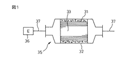
ところで、触媒担体をケーシングに装填する場合、触媒担体の外周に触媒担体保持材を巻回して一体化した後、それを円筒形ケーシングに加圧下に挿入する圧入方式が一般的に採用されている。現在、圧入方式で触媒担体を装填(キャンニングという)する場合の作業性を改善し、触媒担体保持材のクッション性(嵩高性)を高め、さらには触媒担体保持材を構成する無機繊維の空中飛散を防止するため、いろいろなタイプの触媒担体保持材が提案されている。例えば、図1に示すような、触媒担体33と、触媒担体33の外周を覆う金属シェル(ケーシング)32と、触媒担体33とケーシング32との間に配置される保持シール材(触媒担体保持材)31とから構成される触媒コンバータ35において、100cm2の中に50〜3000個の密度でニードルパンチ処理された無機質繊維マットからなり、有機質の含有量が0を超えて大きくかつ2重量%以下であり、かつ0.15〜0.45g/cm3の充填密度において300〜1000℃の間に加熱したときに5〜500kPaの面圧を発生することを特徴とする触媒担体保持材を使用することが提案されている(特許文献4)。触媒コンバータ35は、図示のように、自動車のエンジン36からの排気パイプ37の途中に設けられる。また、キャンニング工程は、図2に示すように、触媒担体保持材31を巻回させた触媒担体33をケーシング32の端部の開口から加圧下に押し込むようにして実施される。
【0005】
また、上記と同様な構成の触媒コンバータにおいて、無機繊維をマット状に配してなるマット状物に0.5〜20重量%の有機バインダ又は無機バインダからなるバインダを添着してなるとともに、組み付け後の充填密度が0.1〜0.6g/cm3の範囲にあるように調整されており、かつ、マット状物に添着されたバインダの固形分割合を厚さ方向に3等分(上部、中部、下部)して評価した場合、上部及び下部におけるバインダの固形分割合が中部のそれに較べて高いことを特徴とする触媒担体保持材を使用することも提案されている(特許文献5)。
【0006】
【特許文献1】
特開昭57−61686号公報(特許請求の範囲)
【特許文献2】
特開昭59−10345号公報(特許請求の範囲)
【特許文献3】
特開昭61−239100号公報(特許請求の範囲)
【特許文献4】
特開2001−259438号公報(特許請求の範囲、図1、図4)
【特許文献5】
特開2002−4848号公報(特許請求の範囲、図1、図3)
【0007】
【発明が解決しようとする課題】
圧入構造を採用した従来の触媒コンバータにおいては、上記したように、通常マットの形で使用される触媒担体保持材にいろいろな改良が施されているけれども、依然として作業性が十分でなく、特性面でもさらなる改良が必要である。例えば、マットの嵩高性を改良したり無機繊維の飛散を防止したりするために有機バインダをマットに含浸したり塗布していることは上記の通りであるが、マット中に含まれる有機バインダが、キャンニング工程におけるマットとケーシングの間の密着を引き起こし、マットの滑りを低下させるために、より大きな圧入荷重が必要となる。また、マットとケーシングの間の密着の度合いが強すぎると、マットとそれに巻回された触媒担体との間に滑りが発生し、触媒担体をケーシングに挿入できない状態が発生する。さらに、マット本体は大きなせん断応力を受けて変形するため、無機繊維の圧壊やそれに伴う保持力の低下、耐風蝕性の低下等も発生する。
【0008】
本発明の目的は、したがって、触媒担体を巻回し保持した状態で触媒コンバータのケーシングに挿入する時に作業性がよく、挿入中に触媒担体と触媒担体保持材とが分離することがなく、しかも耐熱性、面圧保持性、そして耐風蝕性に優れた触媒担体保持材を提供することにある。
【0009】
また、本発明の目的は、構造が簡単であり、製造が容易であり、しかも触媒担体保持材が耐熱性、面圧保持性、そして耐風蝕性に優れた触媒コンバータを提供することにある。
【0010】
さらに、本発明の目的は、触媒担体以外の汚染コントロール要素、例えばフィルター要素などを保持するための汚染コントロール要素の保持材や、そのような保持材を備えた汚染コントロール装置を提供することにある。
【0011】
本発明の上記した目的やその他の目的は、以下の詳細な説明から容易に理解することができるであろう。
【0012】
【課題を解決するための手段】
本発明は、その1つの面において、ケーシング内で汚染コントロール要素を巻回して保持するためのものであって、所定の厚さをもった繊維材料のマットからなり、前記マットのケーシング側の外周面及び汚染コントロール要素側の内周面のそれぞれにおいて少なくとも、高温条件下で分解して消散可能なラテックスからなる摩擦力/密着力コントロール剤が含浸されておりかつ、その際、前記マットの内周面に含浸された前記摩擦力/密着力コントロール剤の固形分含有量が、前記マットの外周面に含浸された前記摩擦力/密着力コントロール剤の固形分含有量よりも大であり、かつ約15〜50g/m2の範囲にあることを特徴とする汚染コントロール要素の保持材にある。
【0013】
また、本発明は、そのもう1つの面において、ケーシングと、該ケーシング内に設置された汚染コントロール要素と、前記ケーシングと前記汚染コントロール要素との間に配置された汚染コントロール要素の保持材とを備える汚染コントロール装置であって、
前記汚染コントロール要素の保持材が、上記のような本発明による汚染コントロール要素の保持材であることを特徴とする汚染コントロール装置にある。
【0014】
【発明の実施の形態】
本発明による汚染コントロール要素保持材及び汚染コントロール装置は、それぞれ、いろいろな形態で有利に実施することができる。例えば、汚染コントロール要素は、触媒担体(あるいは触媒要素)、フィルター要素(例えば、エンジン用排気浄化フィルターなど)あるいはその他の任意の汚染コントロール要素であることができる。同様に、汚染コントロール装置は、それに取り付けられた汚染コントロール要素に応じて、触媒コンバータ、排気浄化装置、例えばエンジン用排気浄化装置(例えば、ディーゼルパティキュレートフィルター装置)あるいはその他の任意の汚染コントロール装置であることができる。以下では特に、触媒担体保持材と触媒コンバータを参照して本発明の実施を説明するが、本発明はこれらの形態にのみ限定されるものではない。
【0015】
本発明による触媒コンバータは、自動車やその他の内燃機関において排気ガスを処理するために特に有利に用いられるものであって、ケーシングと、ケーシング内に設置された触媒担体(触媒要素)とを少なくとも含んでなるように構成される。また、ケーシングと触媒担体との間には、触媒担体の外周面を巻回するようにして、以下において詳細に説明するところの本発明による触媒担体保持材が装着される。なお、従来の触媒コンバータの場合には、触媒担体と触媒担体保持材とを接着剤、粘着テープ等の接合手段を介在させて接合することが一般的であったが、本発明の触媒コンバータの場合、触媒担体保持材自体で十分な密着力を発現することができるので、構成及び製造の複雑化や製造コストの増加を引き起こす接合手段の介在は不要である。また、触媒担体保持材は、通常、触媒担体の実質的に全部を巻回して用いられるけれども、必要ならば、触媒担体の一部のみに装着して用いてもよい。さらに、必要に応じて、ワイヤメッシュなどの固定手段を補助的に使用してもよい。
【0016】
触媒担体保持材は、それをケーシング内に装着した場合に適切な嵩密度となるように、適度に圧縮して使用するのが好ましい。圧縮の手法には、クラムシェル圧縮、スタッフィング圧縮、ターニキット圧縮などがある。本発明の触媒担体保持材は、スタッフィング圧縮などのように、例えば円筒形のケーシングに触媒担体保持材を加圧下に押し込む、いわゆる圧入構造の触媒コンバータの製造において有利に使用することができる。クラムシェル圧縮のように開放可能なケーシングを使用する場合には、円筒形のケーシングに触媒担体保持材を押し込む際に摩擦などの問題が発生しないからである。
【0017】
本発明の触媒コンバータは、それが圧入構造を採用している限り、いろいろなタイプの触媒コンバータを包含することができる。触媒コンバータは、好ましくは、モノリス状に成形された触媒要素を備えた触媒コンバータ、すなわち、モノリス型触媒コンバータである。この触媒コンバータは、ハニカム状の断面の小さな通路を有する触媒要素からなるので、従来のペレット型触媒コンバータに比較して小型であり、排気ガスとの接触面積を十分に確保しながら、排気抵抗を小さく抑えることができ、よって、より効率よく排気ガスの処理を行うことができる。
【0018】
本発明の触媒コンバータは、各種の内燃機関と組み合わせて、その排気ガスの処理に有利に使用することができる。特に、乗用車、バス、トラック等の自動車の排気システムに本発明の触媒コンバータを搭載した時に、その優れた作用効果を十分に発揮させることができる。
【0019】
図3は、本発明による触媒コンバータの典型的な一例を示した側面図であり、構成の容易な理解のため、触媒コンバータの主要部を切断した状態が示されている。また、図4は、図3の触媒コンバータを線分A−Aにそって切断した断面図である。これらの図面から理解されるように、触媒コンバータ10は、金属ケーシング4と、その金属ケーシング4内に配置されたモノリスの固体触媒担体1と、金属ケーシング4と触媒担体1との間に配置された本発明の触媒担体保持材2とを備える。触媒担体保持材2は、以下において図5を参照して詳細に説明するように、所定の厚さをもった繊維材料のマットからなり、前記マットのケーシング側の外周面及び触媒担体側の内周面のそれぞれにおいて少なくとも、高温条件下で分解して消散可能なラテックスからなる摩擦力/密着力コントロール剤が含浸されておりかつ、その際、前記マットの内周面に含浸された前記摩擦力/密着力コントロール剤の固形分含有量が、前記マットの外周面に含浸された前記摩擦力/密着力コントロール剤の固形分含有量よりも大であり、かつ約15〜50g/m2の範囲にあることを特徴とする。触媒コンバータ10には、円錐台の形をした排気ガス流入口12及び排気ガス流出口13が取り付けられている。
【0020】
先に説明したように、本発明の触媒コンバータ10の場合、基本的には触媒担体1と触媒担体保持材2との間に接着剤や粘着シートのような接合手段を介在させることは不要である。しかし、もしも本発明の作用効果に対して悪影響がでず、むしろ触媒担体1と触媒担体保持材2の密着性を改善し、キャンニング作業を促進する効果が期待されるのであるならば、そのような接合手段を補助的に使用してもよい。接合手段は、通常、部分的に使用するのが好ましい。また、触媒担体保持材2は、一般的には必要ないけれども、その表面を損傷などから保護するために保護コーティングを備えていてもよい。
【0021】
さらに具体的に説明すると、金属ケーシング内の固体触媒担体は、通常、複数の排気ガス流路を有するハニカム構造のセラミック製触媒担体からなる。この触媒担体を巻回して、本発明の触媒担体保持材が配置される。触媒担体保持材は、断熱材として機能することの他、触媒担体を金属ケーシングの内部に保持し、触媒担体と金属ケーシングの間にできた隙間を封止しているので、排気ガスが触媒担体をバイパスして流動することを防止するかもしくは、少なくとも、そのような不所望な流動を最小にすることができる。また、触媒担体は、金属ケーシング内においてしっかりと、しかも弾性的に支持される。
【0022】
本発明の触媒コンバータにおいて、その金属ケーシングは、当業界で公知のいろいろな金属材料から、所望とする作用効果などに応じて任意の形状で作製することができる。好適な金属ケーシングは、ステンレス鋼製で、図3に示したような形状を備えたものである。もちろん、必要に応じて、鉄、アルミニウム、チタンなどの金属やその合金などから、任意の適当な形状をもった金属ケーシングを作製してもよい。
【0023】
金属ケーシングと同様に、固体触媒担体も、常用の触媒コンバータにおいて採用されているものと同様な材料から、同様な形状で作製することができる。適切な触媒担体は、当業者に周知であって、金属、セラミックなどから製造されたものを包含する。有用な触媒担体は、例えば、米国再発行特許第27,747号明細書に開示されている。また、セラミック製の触媒担体は、例えば、米国在のコーニング社(Corning Inc.)から商業的に入手可能である。例えば、ハニカム状のセラミック製触媒担体は、コーニング社から「CELCOR」の商品名で、また、NGK社(NGK Insulated Ltd.)から「HONEYCERAM」の商品名で、それぞれ入手可能である。金属製の触媒担体は、例えば、ドイツ在のベール社(Behr GmbH and Co. )から商業的に入手可能である。なお、触媒モノリスについての詳細な説明は、例えば、SAE 技術書の文献第900500号のStroomらの「Systems Approach to Packaging Design for Automotive Catalytic Converters 」、SAE 技術書の文献第800082号のHowittの「Thin Wall Ceramics as Monolithic Catalyst Support 」及びSAE 技術書の文献第740244号のHowittらの「Flow Effect in Monolithic Honeycomb Automotive Catalytic Converter 」を参照されたい。
【0024】
上述のような触媒担体に担持されるべき触媒は、通常、金属(例えば、白金、ルテニウム、オスミウム、ロジウム、イリジウム、ニッケル、パラジウムなど)及び金属酸化物(例えば、五酸化バナジウム、二酸化チタンなど)であり、好ましくは、コーティングの形で用いられる。なお、このような触媒のコーティングについての詳細な説明は、例えば、米国特許第3,441,381号明細書を参照されたい。
【0025】
本発明の実施において、触媒コンバータは、本発明の範囲を逸脱しない限り、いろいろな構成及び方法で任意に製造することができる。触媒コンバータは、基本的に、金属製のケーシングに、例えばハニカム状のセラミック製触媒担体を収容することによって作製し、かつ例えばハニカム状のセラミック製モノリスに、白金、ロジウム及びパラジウムのような貴金属からなる触媒層(触媒のコーティング)を担持させることによって最終的な触媒担体(触媒要素)を作製することが、特に好適である。このような構成を採用することによって、比較的高温で効果的な触媒作用を発現させることができる。
【0026】
本発明に従うと、金属ケーシングとその内部の触媒要素との間に、本発明による触媒担体保持材が配置される。触媒担体保持材は、所定の厚さをもった繊維材料のマット、ブランケット等からなる。触媒担体保持材は、1個の部材から構成されていてもよく、2個もしくはそれ以上の部材から、積層、接合などで構成されていてもよい。触媒担体保持材は、通常、マット、ブランケットなどの形態を有しているのが、取り扱い性などの面から有利であるが、必要ならば、その他の形態であってもよい。触媒担体保持材のサイズは、その使用目的などに応じて、広い範囲で変更することができる。例えば、マット状の触媒担体保持材を自動車の触媒コンバータに装填して使用するような場合には、その保持材は、通常、約1.5〜15mmのマット厚、約200〜500mmの幅、そして約100〜1500mmの長さである。かかる保持材は、必要に応じて、はさみ、カッター等で所望の形状及びサイズに切断して使用してもよい。
【0027】
触媒担体保持材は、好ましくは、無機繊維材料から構成され、さらに好ましくは、アルミナ繊維を含む無機繊維材料から構成される。また、無機繊維材料は、アルミナ繊維とのみ組み合わせて使用してもよいけれども、必要ならばその他の無機材料をさらに併用してもよい。併用可能な無機材料は、以下に列挙するものに限定されるわけではないけれども、シリカ繊維、ガラス繊維、ベントナイト、バーミキュライト、黒鉛などを包含する。これらの無機材料は、単独で使用してもよく、2種以上を混合して一緒に使用してもよい。
【0028】
触媒担体保持材を構成する無機繊維は、好ましくは、アルミナ(Al2O3)とシリカ(SiO2)を含む無機繊維から構成される。ここで、無機繊維は、アルミナ繊維とシリカ繊維の2成分からなり、その際、アルミナ繊維とシリカ繊維の配合比率が、約40:60〜96:4の範囲にあることが好ましい。アルミナ繊維とシリカ繊維の配合比率がこのような範囲を外れると、例えばアルミナ繊維の配合比率が40%を下回ると、耐熱性の悪化といった不具合が発生する。
【0029】
無機繊維は、特にその太さ(平均直径)が限定されないけれども、好適には、約2〜7μm の平均直径を有する。無機繊維が約2μm より小さい平均直径を有していると、脆くて強度不足になる傾向にあり、反対に、約7μm より大きい平均直径を有していると、保持材の成形を困難にする傾向にある。
【0030】
また、太さと同様に、無機繊維の長さも特に限定されるものではない。しかし、無機繊維は、好適には、約0.5〜50mmの平均長さを有する。無機繊維の平均長さが約0.5mmより小さいと、それを使用して保持材を形成した効果などを出すことができなくなり、反対に、約50mmより大きいと、取り扱い性が劣ってくるので、保持材の製造プロセスをスムースに進行することが困難になる。
【0031】
別法によれば、本発明の実施において、主としてアルミナ繊維の積層シートからなるアルミナ質繊維マットもまた触媒担体保持材として有利に使用することができる。このようなアルミナ質繊維マットにおいて、アルミナ繊維の平均長さは、通常、約20〜200mmの範囲であり、また、繊維の太さ(平均直径)は、通常、約1〜40μmの範囲である。また、アルミナ繊維は、Al2O3/SiO2重量比(Al2O3/SiO2)=約70/30〜74/26のムライト組成であることが好ましい。
【0032】
上記のアルミナ質繊維のマットは、例えば、オキシ塩化アルミニウム等のアルミナ源、シリカゾル等のシリカ源、ポリビニルアルコール等の有機バインダ及び水の混合物から成る紡糸原液を使用して製造することができる。すなわち、紡糸したアルミナ繊維前駆体を積層してシート化し、次いで、好ましくはニードルパンチングを施した後、通常、約1000〜1300℃の高温で焼成する。
【0033】
上記のニードルパンチング処理は、繊維の一部を積層面に対して縦方向に配向させる効果がある。従って、シート内のアルミナ繊維前駆体の一部がシートを貫通して縦方向に配向してシートを緊縛するため、シートの嵩比重が高められ、また、層間の剥離や層間のずれが防止される。ニードルパンチングの密度は、広い範囲にわたって変更することができるけれども、通常、約1〜50打/cm2の範囲であり、ニードルパンチングの密度により、マットの厚さ、嵩比重、強度などが調節される。
【0034】
上記したようなアルミナ質繊維マットの製造において、アルミナ繊維にその他のセラミック繊維や無機膨張材を補助的に添加してもよい。この場合、添加材をマットに均一に混合してもよいが、特に加熱される個所を避けて局在させることにより、添加材の性能を維持しつつ低コスト化することが可能である。上記のセラミック繊維としては、シリカ繊維、ガラス繊維などが挙げられ、無機膨張材としては、ベントナイト、膨張性バーミキュライト、膨張性黒鉛などが挙げられる。
【0035】
本発明による触媒担体保持材は、従来の触媒担体保持材が湿式法(無機繊維と有機バインダの混合、無機繊維の開繊、スラリーの調製、抄紙による成形、成形体のプレスの各工程を含む)によって製造されていたのとは対照的に、乾式法で製造される。乾式法は、基本的に、周知かつ慣用の方法に従って実施することができる。典型的には、上記したように、ニードルパンチ等を利用した乾式法が有利である。
【0036】
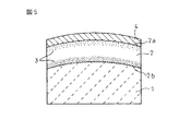
本発明の触媒担体保持材は、図5に模式的に示すように、ケーシング4と、その内部に装填され触媒担体1の間に、触媒担体1の外周面を巻回した状態で挿入された、所定の厚さをもった繊維材料のマット2からなる。このマット状触媒担体保持材2には、ケーシング4の側の外周面2a及び触媒担体1の側の内周面2bのそれぞれにおいて少なくとも、高温条件下で分解して消散可能なラテックスからなる摩擦力/密着力コントロール剤3が含浸されている。なお、ここで、「少なくとも」というのは、摩擦力/密着力コントロール剤3が触媒担体保持材2の厚みの全体にわたって含浸されている状態ばかりでなく、部分的に含浸されている状態、例えば図示のように触媒担体保持材2の中央部に摩擦力/密着力コントロール剤3が含浸されていない状態も本発明の範囲に包含されるからである。なお、摩擦力/密着力コントロール剤3の含浸方法にもよるけれども、摩擦力/密着力コントロール剤3の含浸量は、通常、触媒担体保持材2の表面(外周面、内周面)から内側に向かって減少していく。
【0037】
また、摩擦力/密着力コントロール剤3の含浸は、本発明に従い触媒担体保持材2の外周面2aの側及び内周面2bの側において含浸量に差があるように配慮して行うことが必要である。具体的には、本発明の触媒担体保持材2の場合、その内周面2bの側に含浸された摩擦力/密着力コントロール剤3の固形分含有量が、その外周面2aの側における含有量よりも大である。
【0038】
触媒担体保持材2において、摩擦力/密着力コントロール剤3の含有量の差は特に限定されるわけではないけれども、通常、触媒担体保持材2の内周面2bの側における摩擦力/密着力コントロール剤3の固形分含有量が、約15〜50g/m2の範囲にあることが好ましく、さらに好ましくは、約25〜50g/m2の範囲である。一方、触媒担体保持材2の外周面2aにおける摩擦力/密着力コントロール剤3の固形分含有量は、通常、約2〜8g/m2の範囲にあることが好ましい。なお、触媒担体保持材2における摩擦力/密着力コントロール剤3の固形分含有量が0(ゼロ)である場合には、繊維が飛散する量が多くなり、作業上の環境を考慮すると、好ましくない。
【0039】
本発明の触媒担体保持材において、それに含浸せしめられる摩擦力/密着力コントロール剤は、触媒コンバータの運転時の適用されるような高温条件下で、発生した任意の反応の下で分解して消散可能なラテックスからなる。ここで使用し得るラテックスは、天然もしくは合成の高分子材料、好ましくは例えばブタジエン−スチレン樹脂、ポリスチレン樹脂、ポリ酢酸ビニル樹脂、アクリル樹脂等の樹脂材料を水性媒体あるいはその他の媒体に分散させて得たコロイド状分散液、あるいはポリビニルアルコール等の有機材料である。摩擦力/密着力コントロール剤として、アクリル樹脂を使用したアクリル系のラテックスをとりわけ有利に使用することができる。
【0040】
触媒担体保持材に対する摩擦力/密着力コントロール剤の上述のような含浸は、周知・慣用の技術、すなわち、噴霧、塗布等によって有利に実施することができる。例えば噴霧法は、スプレーを用意して、アクリル系のラテックスなどを触媒担体保持材の両面に順次あるいは同時に噴霧するだけでよいので、作業が簡単であり、経済的でもある。噴霧後のラテックスなどは、自然乾燥してもよく、適温まで加熱して乾燥してもよい。
【0041】
本発明によると、作製後の触媒担体保持材において、アクリル系のラテックスあるいはその他の摩擦力/密着力コントロール剤を上記したように触媒担体の側とケーシングの側とで含浸量が異なるように適用したので、触媒担体保持材と触媒担体の間の密着性をより大きく調整するとができ、かつ触媒担体保持材とケーシングの間では、反対に、両者の間の摩擦力を低減して、キャンニング時、触媒担体保持材がケーシング内を滑りやすくすることができ、また、その結果として、圧入荷重や触媒担体保持材の変形(伸び)を小さく抑えることができる。さらに、触媒担体保持材の圧入を変形を伴わずに行うことができるので、作業性が顕著に改善される。さらにまた、触媒担体保持材の変形量が小さくなったことから、触媒担体保持材自体の保持力特性や耐風蝕性も格段と改善される。
【0042】
【実施例】
引き続いて、本発明をその実施例を参照して説明する。なお、本発明は、これらの実施例によって限定されるものでないことは言うまでもない。
触媒担体保持材(マット)の作製:
マット面密度を異にする3種類のニードルパンチされたアルミナ繊維マット(商品名「マフテック」、三菱化学産資社製)を用意した。これらのアルミナ繊維マットのサイズは、長さ260mm×幅90mm×厚さ12.5mmであった。次いで、それぞれのアルミナ繊維マットの触媒担体(モノリス)との接触面及びケーシングとの接触面のそれぞれに、アクリル系ラテックス(商品名「ニッポールLX816」、日本ゼオン社製)を下記の第1表に記載されるように異なる塗布量(固形分基準)でスプレー塗布した。スプレー濃度は8.4%であった。アクリル系ラテックスを含浸させたアルミナ繊維マットをオーブンに入れ、130℃で20分間加熱乾燥した。
【0043】
別に用意した円筒形状で、外径78mm×長さ100mmの日本碍子社製モノリス体の外周に乾燥後のアルミナ繊維マットを巻き付けた。次いで、アルミナ繊維マットで巻回された触媒担体を、内径84mm×長さ120mmの円筒形ステンレス製ケーシングの内部にガイドコーンを用いて40mm/秒で圧入した。このキャンニング工程において、モノリスとケーシングの間のギャップ(間隙)は、3mmであった。
【0044】
上記のキャンニング工程において、それぞれのアルミナ繊維マットについて最大圧入荷重を測定したところ、下記の第1表にまとめて記載するような測定結果が得られた。また、アルミナ繊維マットの圧入が完了した後、ケーシング内に装填したアルミナ繊維マットの変形量(伸び)をケーシングの端面より測定したところ、下記の第1表にまとめて記載するような測定結果が得られた。
【0045】
【表1】
【0046】
上記第1表に記載の測定結果から理解されるように、アルミナ繊維マットの表面に例えばアクリル系ラテックスのような摩擦力/密着力コントロール剤を異なる量で含浸させることによって、アルミナ繊維マットのキャンニング作業を有意に向上させることができる。
【0047】
特に、アルミナ繊維マットのケーシング側において、アクリル系ラテックスの含浸量を2〜8g/m2の範囲に調整することで、圧入荷重を最適化し、マットの変形を抑制することができる。ラテックスの含浸量が2g/m2を下回ると、アルミナ繊維の飛散を防止できなくなり、反対にラテックスの含浸量が12g/m2もしくはそれ以上となると、マットとケーシングの接着が発生し、含浸量が8g/m2の場合に比較して、圧入荷重やマットの変形が急激に大きくなる。10mm以上の変形は、アルミナ繊維の圧壊や、それに伴う保持力及び耐風蝕性の低下が引き起こされることを意味している。
【0048】
また、アルミナ繊維マットのモノリス側において、アクリル系ラテックスの含浸量を15〜50g/m2の範囲に調整することで、マットとモノリスの密着力を最適化することができ、また、したがって、粘着テープなどの接合手段の使用を不要とすることができる。これに対して、アクリル系ラテックスの含浸量を12g/m2とした時、密着力の最適化を得ることができなかった。これは、ラテックスの含浸量を15〜50g/m2の範囲に調整した時、含浸させたラテックスがマットの表面から内部に向かって固化する傾向にあり、圧入荷重やマットの変形を抑える効果が発現したけれども、アクリル系ラテックスの含浸量を12g/m2とした時にはそのような効果が発現しなかったためであると考察される。
【0049】
【発明の効果】
以上に詳細に説明したように、本発明によれば、触媒担体を巻回し保持した状態で触媒コンバータのケーシングに装入する時に作業性がよく、挿入中に触媒担体と触媒担体保持材とが分離することがなく、しかも耐熱性、面圧保持性、そして耐風蝕性に優れた触媒担体保持材を提供することができる。
【0050】
また、本発明によれば、挿入された触媒担体保持材が断熱、触媒担体保持等面ですぐれている触媒コンバータを提供することができる。
【0051】
さらに、本発明によれば、自動車やその他の内燃機関において、その排気ガスの処理に有利に使用することができる触媒コンバータを提供することができる。
【0052】
さらにまた、本発明は、触媒コンバータ以外の汚染コントロール装置、例えばディーゼルパティキュレートフィルターやその他の排気浄化装置などにおいても上述のようなすぐれた効果を実現することができる。
【図面の簡単な説明】
【図1】従来の触媒コンバータの構成を示した断面図である。
【図2】図1の触媒コンバータにおいて、金属製ケーシングに触媒担体を装填する方法を示した斜視図である。
【図3】本発明による触媒コンバータの構成を示した断面図である。
【図4】図3の触媒コンバータの線分A−Aにそった断面図である。
【図5】図3の触媒コンバータにおいて、触媒担体保持材における摩擦力/密着力コントロール剤の含浸状態を示した断面図である。
【符号の説明】
1…触媒担体
2…触媒担体保持材
3…摩擦力/密着力コントロール剤
4…ケーシング
10…触媒コンバータ[0001]
BACKGROUND OF THE INVENTION
The present invention relates to a holding material for a pollution control element, and more particularly to a holding material for a pollution control element such as a catalyst carrier and a filter element. In particular, the present invention has good workability when inserted into the casing of the catalytic converter in a state where the catalyst carrier is wound and held, the catalyst carrier and the catalyst carrier holding material are not separated during insertion, and the heat resistance, surface The present invention relates to a catalyst carrier holding material excellent in pressure holding property and wind erosion resistance. The present invention also relates to a pollution control device including such a pollution control element holding material, and more specifically, to an exhaust gas purification device including a catalytic converter loaded with a catalyst carrier holding material and a filter element holding material. For example, the catalytic converter of the present invention can be advantageously used for the treatment of exhaust gas in automobiles and other internal combustion engines.
[0002]
[Prior art]
Exhaust gas purification system using ceramic catalytic converter as means for removing carbon monoxide (CO), hydrocarbon (HC), nitrogen oxide (NOx), etc. contained in exhaust gas from automobile engine Is well known. The ceramic catalytic converter basically has a metal casing, in other words, a housing containing, for example, a honeycomb-shaped ceramic catalyst carrier (also referred to as “catalyst element”).
[0003]
As is well known, there are various types of ceramic catalytic converters, but usually the gap between the catalyst support and the casing contained therein, inorganic fibers, organic fibers and / or generally liquids or pastes. The structure which fills up with the heat insulating material typically comprised combining the organic binder in the shape (patent documents 1, 2, and 3) is employ | adopted. As a result, the heat insulating material that fills the gap holds the catalyst carrier, and it is possible to prevent a mechanical shock due to impact, vibration, or the like from being inadvertently applied to the catalyst carrier. In the catalytic converter having such a configuration, therefore, destruction or movement of the catalyst carrier does not occur, so that an intended action can be realized over a long period of time. In addition, since the above heat insulating materials have the function to hold | maintain a catalyst carrier, it is generally called the catalyst carrier holding material.
[0004]
By the way, when the catalyst carrier is loaded in the casing, a press-fitting method is generally adopted in which the catalyst carrier holding material is wound around the outer periphery of the catalyst carrier and integrated, and then inserted into the cylindrical casing under pressure. . Currently, the workability when loading a catalyst carrier by the press-fitting method (referred to as canning) is improved, the cushioning property (bulkyness) of the catalyst carrier holding material is improved, and the inorganic fibers constituting the catalyst carrier holding material are in the air Various types of catalyst carrier holding materials have been proposed to prevent scattering. For example, as shown in FIG. 1, a catalyst carrier 33, a metal shell (casing) 32 that covers the outer periphery of the catalyst carrier 33, and a holding seal material (catalyst carrier holding material) disposed between the catalyst carrier 33 and the casing 32. ) 31 in a catalytic converter 35 comprising 100 cm 2 The inorganic fiber mat is needle punched at a density of 50 to 3000, and the organic content is greater than 0 and less than 2% by weight, and 0.15 to 0.45 g / cm. 3 It has been proposed to use a catalyst carrier holding material characterized by generating a surface pressure of 5 to 500 kPa when heated at a packing density of 300 to 1000 ° C. (Patent Document 4). As shown in the figure, the catalytic converter 35 is provided in the middle of an exhaust pipe 37 from an automobile engine 36. As shown in FIG. 2, the canning step is performed by pressing the catalyst carrier 33 around which the catalyst carrier holding material 31 is wound from the opening of the end portion of the casing 32 under pressure.
[0005]
Moreover, in the catalytic converter having the same configuration as described above, the matte material in which inorganic fibers are arranged in a mat shape is attached with a binder of 0.5 to 20% by weight of an organic binder or an inorganic binder and assembled. Subsequent packing density is 0.1-0.6 g / cm 3 When the solid content ratio of the binder attached to the mat-like material is divided into three equal parts (upper part, middle part, lower part) in the thickness direction, the upper and lower parts are evaluated. It has also been proposed to use a catalyst carrier holding material characterized in that the solid content ratio of the binder is higher than that of the middle part (Patent Document 5).
[0006]
[Patent Document 1]
JP-A-57-61686 (Claims)
[Patent Document 2]
JP 59-10345 A (Claims)
[Patent Document 3]
JP 61-239100 A (Claims)
[Patent Document 4]
JP 2001-259438 A (Claims, FIGS. 1 and 4)
[Patent Document 5]
Japanese Patent Laying-Open No. 2002-4848 (Claims, FIGS. 1 and 3)
[0007]
[Problems to be solved by the invention]
In the conventional catalytic converter adopting the press-fitting structure, as described above, although various improvements have been made to the catalyst carrier holding material that is usually used in the form of a mat, the workability is still insufficient, and the characteristic aspect But further improvements are needed. For example, as described above, the mat is impregnated with or coated with an organic binder in order to improve the bulkiness of the mat or prevent scattering of inorganic fibers, but the organic binder contained in the mat is as described above. In order to cause close contact between the mat and the casing in the canning process and to reduce the sliding of the mat, a larger press-fitting load is required. If the degree of close contact between the mat and the casing is too strong, slippage occurs between the mat and the catalyst carrier wound around the mat, and a state in which the catalyst carrier cannot be inserted into the casing occurs. Furthermore, since the mat body is deformed by receiving a large shear stress, the inorganic fibers are crushed, the holding force is lowered, and the erosion resistance is lowered.
[0008]
Therefore, the object of the present invention is to improve the workability when inserting the catalyst carrier into the catalytic converter casing in a state where the catalyst carrier is wound and held, and the catalyst carrier and the catalyst carrier holding material are not separated during the insertion, and the heat resistance is high. It is an object to provide a catalyst carrier holding material having excellent properties, surface pressure holding properties, and wind erosion resistance.
[0009]
Another object of the present invention is to provide a catalytic converter that has a simple structure, is easy to manufacture, and has a catalyst carrier holding material that is excellent in heat resistance, surface pressure holding ability, and wind erosion resistance.
[0010]
Furthermore, an object of the present invention is to provide a pollution control element holding material for holding a pollution control element other than the catalyst carrier, for example, a filter element, and a pollution control device provided with such a holding material. .
[0011]
These and other objects of the present invention will be readily understood from the following detailed description.
[0012]
[Means for Solving the Problems]
In one aspect thereof, the present invention is for winding and holding a pollution control element in a casing, comprising a mat of fiber material having a predetermined thickness, the outer periphery of the mat on the casing side Each of the surface and the inner peripheral surface on the contamination control element side is impregnated with at least a frictional force / adhesion force control agent made of latex that can be decomposed and dissipated under high temperature conditions, and at that time, the inner periphery of the mat The solid content of the friction force / adhesion force control agent impregnated on the surface is greater than the solid content of the friction force / adhesion force control agent impregnated on the outer peripheral surface of the mat, and about 15-50 g / m 2 It is in the holding | maintenance material of the pollution control element characterized by being in the range of.
[0013]
According to another aspect of the present invention, there is provided a casing, a contamination control element installed in the casing, and a contaminant control element holding member disposed between the casing and the contamination control element. A pollution control device comprising:
In the pollution control device, the holding material for the pollution control element is the holding material for the pollution control element according to the present invention as described above.
[0014]
DETAILED DESCRIPTION OF THE INVENTION
Each of the contamination control element holding member and the contamination control device according to the present invention can be advantageously implemented in various forms. For example, the pollution control element can be a catalyst carrier (or catalyst element), a filter element (eg, an engine exhaust purification filter, etc.) or any other pollution control element. Similarly, the pollution control device may be a catalytic converter, an exhaust purification device, such as an engine exhaust purification device (eg, a diesel particulate filter device) or any other pollution control device, depending on the pollution control element attached thereto. Can be. In the following, the implementation of the present invention will be described with reference to the catalyst carrier holding material and the catalytic converter, but the present invention is not limited to these embodiments.
[0015]
The catalytic converter according to the present invention is particularly advantageously used for treating exhaust gas in automobiles and other internal combustion engines, and includes at least a casing and a catalyst carrier (catalyst element) installed in the casing. It is comprised so that it may become. A catalyst carrier holding material according to the present invention, which will be described in detail below, is mounted between the casing and the catalyst carrier so as to wind the outer peripheral surface of the catalyst carrier. In the case of the conventional catalytic converter, the catalyst carrier and the catalyst carrier holding material are generally joined together with a joining means such as an adhesive or an adhesive tape. In this case, since the catalyst carrier holding material itself can exhibit a sufficient adhesion force, it is not necessary to intervene a joining means that causes a complicated configuration and an increase in manufacturing cost. Further, the catalyst carrier holding material is usually used by winding substantially the whole catalyst carrier, but if necessary, it may be used by being attached to only a part of the catalyst carrier. Furthermore, you may use fixing means, such as a wire mesh, auxiliary as needed.
[0016]
The catalyst carrier holding material is preferably used after being appropriately compressed so as to have an appropriate bulk density when it is mounted in the casing. Compression methods include clamshell compression, stuffing compression, and Tanikit compression. The catalyst carrier holding material of the present invention can be advantageously used in the production of a so-called press-fitted catalytic converter in which the catalyst carrier holding material is pushed into a cylindrical casing under pressure, such as stuffing compression. This is because when a casing that can be opened, such as clamshell compression, is used, problems such as friction do not occur when the catalyst carrier holding material is pushed into the cylindrical casing.
[0017]
The catalytic converter of the present invention can include various types of catalytic converters as long as it employs a press-fit structure. The catalytic converter is preferably a catalytic converter comprising a monolithic catalytic element, ie a monolithic catalytic converter. Since this catalytic converter is composed of a catalytic element having a small passage having a honeycomb-like cross section, it is smaller than a conventional pellet type catalytic converter, and has an exhaust resistance while ensuring a sufficient contact area with the exhaust gas. Thus, the exhaust gas can be treated more efficiently.
[0018]
The catalytic converter of the present invention can be advantageously used for treating exhaust gas in combination with various internal combustion engines. In particular, when the catalytic converter of the present invention is mounted on an exhaust system of an automobile such as a passenger car, a bus, or a truck, the excellent operational effects can be sufficiently exhibited.
[0019]
FIG. 3 is a side view showing a typical example of the catalytic converter according to the present invention, in which the main part of the catalytic converter is cut for easy understanding of the configuration. FIG. 4 is a cross-sectional view of the catalytic converter of FIG. 3 cut along the line AA. As can be understood from these drawings, the catalytic converter 10 is disposed between the metal casing 4, the monolithic solid catalyst support 1 disposed in the metal casing 4, and the metal casing 4 and the catalyst support 1. And a catalyst carrier holding material 2 of the present invention. As will be described in detail below with reference to FIG. 5, the catalyst carrier holding material 2 is composed of a mat of fiber material having a predetermined thickness, and the inner surface on the casing side and the inner side of the catalyst carrier side of the mat. Each of the peripheral surfaces is impregnated with at least a friction force / adhesion force control agent composed of latex that can be decomposed and dissipated under high temperature conditions, and the friction force impregnated on the inner peripheral surface of the mat at that time The solid content of the adhesion control agent is greater than the solid content of the friction force / adhesion control agent impregnated on the outer peripheral surface of the mat, and about 15 to 50 g / m 2 It is characterized by being in the range of An exhaust gas inlet 12 and an exhaust gas outlet 13 in the shape of a truncated cone are attached to the catalytic converter 10.
[0020]
As described above, in the case of the catalytic converter 10 of the present invention, basically, it is unnecessary to interpose a joining means such as an adhesive or an adhesive sheet between the catalyst carrier 1 and the catalyst carrier holding material 2. is there. However, if the effect of the present invention is not adversely affected, but rather the effect of improving the adhesion between the catalyst carrier 1 and the catalyst carrier holding material 2 and promoting the canning operation is expected. Such a joining means may be used as an auxiliary. The joining means is usually preferably used partially. The catalyst carrier holding material 2 may be provided with a protective coating in order to protect its surface from damage and the like although it is not generally necessary.
[0021]
More specifically, the solid catalyst carrier in the metal casing is usually composed of a ceramic catalyst carrier having a honeycomb structure having a plurality of exhaust gas passages. The catalyst carrier holding material of the present invention is arranged by winding the catalyst carrier. In addition to functioning as a heat insulating material, the catalyst carrier holding material holds the catalyst carrier inside the metal casing and seals the gap formed between the catalyst carrier and the metal casing, so that the exhaust gas is contained in the catalyst carrier. Can be prevented from flowing, or at least such unwanted flow can be minimized. In addition, the catalyst carrier is firmly and elastically supported in the metal casing.
[0022]
In the catalytic converter of the present invention, the metal casing can be made from various metal materials known in the art in any shape depending on the desired effect. A suitable metal casing is made of stainless steel and has a shape as shown in FIG. Of course, if necessary, a metal casing having any appropriate shape may be produced from a metal such as iron, aluminum, titanium, or an alloy thereof.
[0023]
Similar to the metal casing, the solid catalyst carrier can also be made in the same shape from the same material used in conventional catalytic converters. Suitable catalyst supports are well known to those skilled in the art and include those made from metals, ceramics, and the like. Useful catalyst supports are disclosed, for example, in US Reissue Pat. No. 27,747. Ceramic catalyst supports are commercially available from, for example, Corning Inc., USA. For example, a honeycomb-shaped ceramic catalyst support is available from Corning under the trade name “CELCOR” and from NGK (NGK Insulated Ltd.) under the trade name “HONEYCERAM”. Metal catalyst supports are commercially available from, for example, Behr GmbH and Co., Germany. A detailed description of the catalyst monolith can be found in, for example, “Systems Approach to Packing Design for Catalytic Converters” of SAE Technical Document No. 900500 of SAE Technical Document, “h” of Technical Document No. 800082 of SAE Technical Document. See Wall Ceramics as Monolithic Catalytic Support, and "Effective in Monolithic Automatic Catalytic Converter" by Howitt et al. In SAE Technical Document No. 740244.
[0024]
The catalyst to be supported on the catalyst carrier as described above is usually a metal (eg, platinum, ruthenium, osmium, rhodium, iridium, nickel, palladium, etc.) and a metal oxide (eg, vanadium pentoxide, titanium dioxide, etc.). And is preferably used in the form of a coating. For a detailed description of such a catalyst coating, see, for example, US Pat. No. 3,441,381.
[0025]
In the practice of the present invention, the catalytic converter can be arbitrarily manufactured in various configurations and methods without departing from the scope of the present invention. Catalytic converters are basically made by housing, for example, a honeycomb-shaped ceramic catalyst carrier in a metal casing, and from a noble metal such as platinum, rhodium and palladium, for example, in a honeycomb-shaped ceramic monolith. It is particularly suitable to produce the final catalyst support (catalyst element) by supporting the resulting catalyst layer (catalyst coating). By adopting such a configuration, an effective catalytic action can be exhibited at a relatively high temperature.
[0026]
According to the invention, the catalyst carrier holding material according to the invention is arranged between the metal casing and the catalyst element inside. The catalyst carrier holding material is made of a fiber material mat, blanket or the like having a predetermined thickness. The catalyst carrier holding material may be composed of one member, or may be composed of two or more members by lamination, bonding, or the like. The catalyst carrier holding material is usually in the form of a mat, a blanket, etc., which is advantageous from the standpoint of handleability, but may be in other forms if necessary. The size of the catalyst carrier holding material can be changed in a wide range according to the purpose of use. For example, when a mat-like catalyst carrier holding material is used by being loaded into an automobile catalytic converter, the holding material usually has a mat thickness of about 1.5 to 15 mm, a width of about 200 to 500 mm, And it is about 100-1500 mm in length. Such a holding material may be used after being cut into a desired shape and size with scissors, a cutter or the like, if necessary.
[0027]
The catalyst carrier holding material is preferably made of an inorganic fiber material, and more preferably made of an inorganic fiber material containing alumina fibers. Further, the inorganic fiber material may be used only in combination with the alumina fiber, but if necessary, other inorganic material may be further used in combination. Inorganic materials that can be used in combination include, but are not limited to, those listed below, and include silica fiber, glass fiber, bentonite, vermiculite, graphite, and the like. These inorganic materials may be used alone or in combination of two or more.
[0028]
The inorganic fiber constituting the catalyst carrier holding material is preferably alumina (Al 2 O 3 ) And silica (SiO 2 ). Here, the inorganic fiber is composed of two components, an alumina fiber and a silica fiber, and the blending ratio of the alumina fiber and the silica fiber is preferably in the range of about 40:60 to 96: 4. When the mixing ratio of the alumina fiber and the silica fiber is out of such a range, for example, when the mixing ratio of the alumina fiber is less than 40%, a problem such as deterioration of heat resistance occurs.
[0029]
The inorganic fiber is not particularly limited in its thickness (average diameter), but preferably has an average diameter of about 2 to 7 μm. If the inorganic fiber has an average diameter smaller than about 2 μm, it tends to be brittle and insufficient in strength, whereas if it has an average diameter larger than about 7 μm, it becomes difficult to mold the holding material. There is a tendency.
[0030]
Further, like the thickness, the length of the inorganic fiber is not particularly limited. However, the inorganic fibers preferably have an average length of about 0.5-50 mm. If the average length of the inorganic fibers is less than about 0.5 mm, the effect of forming a holding material using the inorganic fibers cannot be obtained. On the other hand, if the average length is greater than about 50 mm, the handleability is inferior. This makes it difficult to smoothly advance the manufacturing process of the holding material.
[0031]
According to another method, in the practice of the present invention, an alumina fiber mat mainly composed of a laminated sheet of alumina fibers can also be advantageously used as a catalyst carrier holding material. In such an alumina fiber mat, the average length of the alumina fibers is usually in the range of about 20 to 200 mm, and the thickness (average diameter) of the fibers is usually in the range of about 1 to 40 μm. . Alumina fiber is Al 2 O 3 / SiO 2 Weight ratio (Al 2 O 3 / SiO 2 ) = Preferred mullite composition of about 70/30 to 74/26.
[0032]
The above-mentioned alumina fiber mat can be produced, for example, by using a spinning dope comprising a mixture of an alumina source such as aluminum oxychloride, a silica source such as silica sol, an organic binder such as polyvinyl alcohol, and water. That is, the spun alumina fiber precursor is laminated to form a sheet, and then preferably subjected to needle punching, and is usually fired at a high temperature of about 1000 to 1300 ° C.
[0033]
Said needle punching process has the effect of orienting a part of fiber to the vertical direction with respect to the lamination surface. Therefore, a part of the alumina fiber precursor in the sheet penetrates the sheet and is oriented in the longitudinal direction to bind the sheet, so that the bulk specific gravity of the sheet is increased, and delamination and delamination between layers are prevented. The Needle punching density can vary over a wide range, but is typically about 1-50 strokes / cm. 2 The mat thickness, bulk specific gravity, strength, etc. are adjusted by the density of needle punching.
[0034]
In the production of the alumina fiber mat as described above, other ceramic fibers or inorganic expansion material may be supplementarily added to the alumina fibers. In this case, the additive may be uniformly mixed in the mat, but it is possible to reduce the cost while maintaining the performance of the additive by avoiding a particularly heated portion and localizing it. Examples of the ceramic fiber include silica fiber and glass fiber, and examples of the inorganic expansion material include bentonite, expandable vermiculite, and expandable graphite.
[0035]
In the catalyst carrier holding material according to the present invention, the conventional catalyst carrier holding material includes each step of a wet method (mixing of inorganic fibers and organic binders, opening of inorganic fibers, preparation of slurry, molding by papermaking, and pressing of the molded body). In contrast to those produced by). The dry method can be basically carried out according to a well-known and conventional method. Typically, as described above, a dry method using a needle punch or the like is advantageous.
[0036]
As schematically shown in FIG. 5, the catalyst carrier holding material of the present invention is inserted between the casing 4 and the catalyst carrier 1 loaded in the casing 4 in a state where the outer peripheral surface of the catalyst carrier 1 is wound. And a mat 2 of a fiber material having a predetermined thickness. The mat-like catalyst carrier holding material 2 has a frictional force composed of latex that can be decomposed and dissipated at high temperatures on at least the outer peripheral surface 2a on the casing 4 side and the inner peripheral surface 2b on the catalyst carrier 1 side. / The adhesion control agent 3 is impregnated. Here, “at least” means not only a state where the friction force / adhesion force control agent 3 is impregnated over the entire thickness of the catalyst carrier holding material 2 but also a state where it is partially impregnated, for example, This is because a state in which the friction force / adhesion force control agent 3 is not impregnated in the central portion of the catalyst carrier holding material 2 as shown in the drawing is also included in the scope of the present invention. Although depending on the impregnation method of the friction force / adhesion force control agent 3, the amount of impregnation of the friction force / adhesion force control agent 3 is usually from the surface (outer peripheral surface, inner peripheral surface) of the catalyst carrier holding material 2 to the inside. It decreases toward.
[0037]
Further, the impregnation of the friction force / adhesion force control agent 3 is performed in consideration of the difference in the impregnation amount on the outer peripheral surface 2a side and the inner peripheral surface 2b side of the catalyst carrier holding material 2 according to the present invention. is necessary. Specifically, in the case of the catalyst carrier holding material 2 of the present invention, the solid content of the frictional force / adhesion force control agent 3 impregnated on the inner peripheral surface 2b side is contained on the outer peripheral surface 2a side. Greater than the amount.
[0038]
The difference in the content of the friction force / adhesion force control agent 3 in the catalyst carrier holding material 2 is not particularly limited. The solid content of the control agent 3 is about 15 to 50 g / m. 2 Preferably in the range of about 25 to 50 g / m. 2 Range. On the other hand, the solid content of the friction force / adhesion force control agent 3 on the outer peripheral surface 2a of the catalyst carrier holding material 2 is usually about 2 to 8 g / m. 2 It is preferable that it exists in the range. In addition, when the solid content of the friction force / adhesion force control agent 3 in the catalyst carrier holding material 2 is 0 (zero), the amount of scattered fibers increases, which is preferable in consideration of the working environment. Absent.
[0039]
In the catalyst carrier holding material of the present invention, the friction force / adhesion force control agent impregnated therein decomposes and dissipates under any reaction that occurs under high temperature conditions as applied during operation of the catalytic converter. Made of possible latex. The latex that can be used here is obtained by dispersing a natural or synthetic polymer material, preferably a resin material such as butadiene-styrene resin, polystyrene resin, polyvinyl acetate resin, or acrylic resin, in an aqueous medium or other medium. A colloidal dispersion or an organic material such as polyvinyl alcohol. As a friction force / adhesion force control agent, an acrylic latex using an acrylic resin can be used particularly advantageously.
[0040]
The above-described impregnation of the friction force / adhesion force control agent with respect to the catalyst carrier holding material can be advantageously carried out by well-known and conventional techniques, that is, spraying, coating, and the like. For example, the spraying method is simple and economical because it is only necessary to prepare a spray and spray an acrylic latex or the like sequentially or simultaneously on both sides of the catalyst carrier holding material. The latex after spraying may be naturally dried or dried by heating to an appropriate temperature.
[0041]
According to the present invention, in the prepared catalyst carrier holding material, acrylic latex or other friction force / adhesion force control agent is applied so that the impregnation amount is different between the catalyst carrier side and the casing side as described above. As a result, the adhesion between the catalyst carrier holding material and the catalyst carrier can be adjusted to a greater degree, and between the catalyst carrier holding material and the casing, on the contrary, the frictional force between the two can be reduced and the canning can be performed. At this time, the catalyst carrier holding material can be easily slid in the casing, and as a result, the press-fitting load and the deformation (elongation) of the catalyst carrier holding material can be kept small. Furthermore, since the press-fitting of the catalyst carrier holding material can be performed without deformation, workability is remarkably improved. Furthermore, since the amount of deformation of the catalyst carrier holding material is reduced, the holding force characteristics and wind erosion resistance of the catalyst carrier holding material itself are remarkably improved.
[0042]
【Example】
Subsequently, the present invention will be described with reference to examples thereof. Needless to say, the present invention is not limited to these examples.
Preparation of catalyst carrier holding material (mat):
Three types of needle-punched alumina fiber mats (trade name “Maftec”, manufactured by Mitsubishi Chemical Corporation) with different mat surface densities were prepared. The size of these alumina fiber mats was 260 mm long × 90 mm wide × 12.5 mm thick. Next, acrylic latex (trade name “Nippol LX816”, manufactured by Nippon Zeon Co., Ltd.) is applied to each of the contact surface of each alumina fiber mat with the catalyst carrier (monolith) and the contact surface with the casing in Table 1 below. Spray coating was performed at different coating amounts (based on solids) as described. The spray concentration was 8.4%. The alumina fiber mat impregnated with the acrylic latex was put in an oven and dried by heating at 130 ° C. for 20 minutes.
[0043]
A dried alumina fiber mat was wound around the outer periphery of a monolith body manufactured by Nippon Choshi Co., Ltd. having an outer diameter of 78 mm and a length of 100 mm. Next, the catalyst support wound with an alumina fiber mat was press-fitted at 40 mm / second into a cylindrical stainless steel casing having an inner diameter of 84 mm and a length of 120 mm using a guide cone. In this canning process, the gap (gap) between the monolith and the casing was 3 mm.
[0044]
In the above canning process, when the maximum press-fitting load was measured for each alumina fiber mat, the measurement results as summarized in Table 1 below were obtained. Further, after the press-fitting of the alumina fiber mat was completed, the deformation amount (elongation) of the alumina fiber mat loaded in the casing was measured from the end surface of the casing. Obtained.
[0045]
[Table 1]
[0046]
As understood from the measurement results shown in Table 1, the alumina fiber mat can be impregnated by impregnating the surface of the alumina fiber mat with different amounts of friction / adhesion force control agents such as acrylic latex. The ning operation can be significantly improved.
[0047]
Particularly, on the casing side of the alumina fiber mat, the impregnation amount of the acrylic latex is 2 to 8 g / m. 2 By adjusting to this range, the press-fit load can be optimized and deformation of the mat can be suppressed. Latex impregnation amount is 2 g / m 2 If it is less than 1, the dispersion of alumina fibers cannot be prevented, and the amount of latex impregnation is 12 g / m. 2 Otherwise, the mat and the casing are bonded, and the impregnation amount is 8 g / m. 2 Compared with the case, the press-fitting load and the deformation of the mat are rapidly increased. The deformation of 10 mm or more means that the alumina fiber is crushed and the accompanying holding force and wind erosion resistance are reduced.
[0048]
Moreover, the impregnation amount of acrylic latex is 15 to 50 g / m on the monolith side of the alumina fiber mat. 2 By adjusting to this range, it is possible to optimize the adhesion between the mat and the monolith, and it is therefore possible to eliminate the use of a joining means such as an adhesive tape. In contrast, the amount of acrylic latex impregnated was 12 g / m. 2 As a result, it was impossible to optimize the adhesion. This is a latex impregnation amount of 15-50 g / m 2 When adjusted to the above range, the impregnated latex tends to solidify from the surface of the mat toward the inside, and the effect of suppressing the press-fitting load and the deformation of the mat is expressed, but the impregnation amount of the acrylic latex is 12 g / m. 2 It is considered that this is because such an effect did not appear.
[0049]
【The invention's effect】
As described above in detail, according to the present invention, when the catalyst carrier is wound and held, it is easy to work when inserted into the casing of the catalytic converter, and the catalyst carrier and the catalyst carrier holding material are inserted during insertion. It is possible to provide a catalyst carrier holding material that does not separate and is excellent in heat resistance, surface pressure holding property, and wind erosion resistance.
[0050]
Further, according to the present invention, it is possible to provide a catalytic converter in which the inserted catalyst carrier holding material is excellent in heat insulation, catalyst carrier holding and the like.
[0051]
Furthermore, according to the present invention, it is possible to provide a catalytic converter that can be used advantageously in the treatment of exhaust gas in automobiles and other internal combustion engines.
[0052]
Furthermore, the present invention can achieve the above-described excellent effects even in pollution control devices other than catalytic converters, such as diesel particulate filters and other exhaust purification devices.
[Brief description of the drawings]
FIG. 1 is a cross-sectional view showing a configuration of a conventional catalytic converter.
2 is a perspective view showing a method for loading a catalyst carrier into a metal casing in the catalytic converter of FIG. 1; FIG.
FIG. 3 is a cross-sectional view showing a configuration of a catalytic converter according to the present invention.
4 is a cross-sectional view taken along line AA of the catalytic converter of FIG. 3. FIG.
5 is a cross-sectional view showing an impregnation state of a friction force / adhesion force control agent in a catalyst carrier holding material in the catalytic converter of FIG. 3;
[Explanation of symbols]
1 ... Catalyst carrier
2 ... Catalyst carrier holding material
3. Friction / adhesion strength control agent
4 ... Casing
10 ... Catalytic converter