JP2008544453A - Hydrogen generating fuel cell cartridge - Google Patents
Hydrogen generating fuel cell cartridge Download PDFInfo
- Publication number
- JP2008544453A JP2008544453A JP2008517030A JP2008517030A JP2008544453A JP 2008544453 A JP2008544453 A JP 2008544453A JP 2008517030 A JP2008517030 A JP 2008517030A JP 2008517030 A JP2008517030 A JP 2008517030A JP 2008544453 A JP2008544453 A JP 2008544453A
- Authority
- JP
- Japan
- Prior art keywords
- fuel component
- reaction chamber
- gas generator
- fuel
- gas
- Prior art date
- Legal status (The legal status is an assumption and is not a legal conclusion. Google has not performed a legal analysis and makes no representation as to the accuracy of the status listed.)
- Pending
Links
Images


Classifications
-
- H—ELECTRICITY
- H01—ELECTRIC ELEMENTS
- H01M—PROCESSES OR MEANS, e.g. BATTERIES, FOR THE DIRECT CONVERSION OF CHEMICAL ENERGY INTO ELECTRICAL ENERGY
- H01M8/00—Fuel cells; Manufacture thereof
- H01M8/04—Auxiliary arrangements, e.g. for control of pressure or for circulation of fluids
- H01M8/04082—Arrangements for control of reactant parameters, e.g. pressure or concentration
- H01M8/04201—Reactant storage and supply, e.g. means for feeding, pipes
- H01M8/04208—Cartridges, cryogenic media or cryogenic reservoirs
-
- H—ELECTRICITY
- H01—ELECTRIC ELEMENTS
- H01M—PROCESSES OR MEANS, e.g. BATTERIES, FOR THE DIRECT CONVERSION OF CHEMICAL ENERGY INTO ELECTRICAL ENERGY
- H01M8/00—Fuel cells; Manufacture thereof
- H01M8/04—Auxiliary arrangements, e.g. for control of pressure or for circulation of fluids
-
- B—PERFORMING OPERATIONS; TRANSPORTING
- B01—PHYSICAL OR CHEMICAL PROCESSES OR APPARATUS IN GENERAL
- B01J—CHEMICAL OR PHYSICAL PROCESSES, e.g. CATALYSIS OR COLLOID CHEMISTRY; THEIR RELEVANT APPARATUS
- B01J7/00—Apparatus for generating gases
- B01J7/02—Apparatus for generating gases by wet methods
-
- B—PERFORMING OPERATIONS; TRANSPORTING
- B01—PHYSICAL OR CHEMICAL PROCESSES OR APPARATUS IN GENERAL
- B01J—CHEMICAL OR PHYSICAL PROCESSES, e.g. CATALYSIS OR COLLOID CHEMISTRY; THEIR RELEVANT APPARATUS
- B01J8/00—Chemical or physical processes in general, conducted in the presence of fluids and solid particles; Apparatus for such processes
- B01J8/08—Chemical or physical processes in general, conducted in the presence of fluids and solid particles; Apparatus for such processes with moving particles
- B01J8/082—Controlling processes
-
- C—CHEMISTRY; METALLURGY
- C01—INORGANIC CHEMISTRY
- C01B—NON-METALLIC ELEMENTS; COMPOUNDS THEREOF; METALLOIDS OR COMPOUNDS THEREOF NOT COVERED BY SUBCLASS C01C
- C01B3/00—Hydrogen; Gaseous mixtures containing hydrogen; Separation of hydrogen from mixtures containing it; Purification of hydrogen
- C01B3/02—Production of hydrogen or of gaseous mixtures containing a substantial proportion of hydrogen
- C01B3/06—Production of hydrogen or of gaseous mixtures containing a substantial proportion of hydrogen by reaction of inorganic compounds containing electro-positively bound hydrogen, e.g. water, acids, bases, ammonia, with inorganic reducing agents
- C01B3/065—Production of hydrogen or of gaseous mixtures containing a substantial proportion of hydrogen by reaction of inorganic compounds containing electro-positively bound hydrogen, e.g. water, acids, bases, ammonia, with inorganic reducing agents from a hydride
-
- C—CHEMISTRY; METALLURGY
- C01—INORGANIC CHEMISTRY
- C01B—NON-METALLIC ELEMENTS; COMPOUNDS THEREOF; METALLOIDS OR COMPOUNDS THEREOF NOT COVERED BY SUBCLASS C01C
- C01B3/00—Hydrogen; Gaseous mixtures containing hydrogen; Separation of hydrogen from mixtures containing it; Purification of hydrogen
- C01B3/02—Production of hydrogen or of gaseous mixtures containing a substantial proportion of hydrogen
- C01B3/32—Production of hydrogen or of gaseous mixtures containing a substantial proportion of hydrogen by reaction of gaseous or liquid organic compounds with gasifying agents, e.g. water, carbon dioxide, air
-
- C—CHEMISTRY; METALLURGY
- C10—PETROLEUM, GAS OR COKE INDUSTRIES; TECHNICAL GASES CONTAINING CARBON MONOXIDE; FUELS; LUBRICANTS; PEAT
- C10J—PRODUCTION OF PRODUCER GAS, WATER-GAS, SYNTHESIS GAS FROM SOLID CARBONACEOUS MATERIAL, OR MIXTURES CONTAINING THESE GASES; CARBURETTING AIR OR OTHER GASES
- C10J3/00—Production of combustible gases containing carbon monoxide from solid carbonaceous fuels
- C10J3/02—Fixed-bed gasification of lump fuel
- C10J3/06—Continuous processes
-
- F—MECHANICAL ENGINEERING; LIGHTING; HEATING; WEAPONS; BLASTING
- F16—ENGINEERING ELEMENTS AND UNITS; GENERAL MEASURES FOR PRODUCING AND MAINTAINING EFFECTIVE FUNCTIONING OF MACHINES OR INSTALLATIONS; THERMAL INSULATION IN GENERAL
- F16L—PIPES; JOINTS OR FITTINGS FOR PIPES; SUPPORTS FOR PIPES, CABLES OR PROTECTIVE TUBING; MEANS FOR THERMAL INSULATION IN GENERAL
- F16L37/00—Couplings of the quick-acting type
- F16L37/28—Couplings of the quick-acting type with fluid cut-off means
- F16L37/30—Couplings of the quick-acting type with fluid cut-off means with fluid cut-off means in each of two pipe-end fittings
- F16L37/32—Couplings of the quick-acting type with fluid cut-off means with fluid cut-off means in each of two pipe-end fittings at least one of two lift valves being opened automatically when the coupling is applied
- F16L37/34—Couplings of the quick-acting type with fluid cut-off means with fluid cut-off means in each of two pipe-end fittings at least one of two lift valves being opened automatically when the coupling is applied at least one of the lift valves being of the sleeve type, i.e. a sleeve is telescoped over an inner cylindrical wall
-
- H—ELECTRICITY
- H01—ELECTRIC ELEMENTS
- H01M—PROCESSES OR MEANS, e.g. BATTERIES, FOR THE DIRECT CONVERSION OF CHEMICAL ENERGY INTO ELECTRICAL ENERGY
- H01M8/00—Fuel cells; Manufacture thereof
- H01M8/06—Combination of fuel cells with means for production of reactants or for treatment of residues
- H01M8/0606—Combination of fuel cells with means for production of reactants or for treatment of residues with means for production of gaseous reactants
- H01M8/065—Combination of fuel cells with means for production of reactants or for treatment of residues with means for production of gaseous reactants by dissolution of metals or alloys; by dehydriding metallic substances
-
- C—CHEMISTRY; METALLURGY
- C01—INORGANIC CHEMISTRY
- C01B—NON-METALLIC ELEMENTS; COMPOUNDS THEREOF; METALLOIDS OR COMPOUNDS THEREOF NOT COVERED BY SUBCLASS C01C
- C01B2203/00—Integrated processes for the production of hydrogen or synthesis gas
- C01B2203/06—Integration with other chemical processes
- C01B2203/066—Integration with other chemical processes with fuel cells
-
- F—MECHANICAL ENGINEERING; LIGHTING; HEATING; WEAPONS; BLASTING
- F17—STORING OR DISTRIBUTING GASES OR LIQUIDS
- F17C—VESSELS FOR CONTAINING OR STORING COMPRESSED, LIQUEFIED OR SOLIDIFIED GASES; FIXED-CAPACITY GAS-HOLDERS; FILLING VESSELS WITH, OR DISCHARGING FROM VESSELS, COMPRESSED, LIQUEFIED, OR SOLIDIFIED GASES
- F17C11/00—Use of gas-solvents or gas-sorbents in vessels
- F17C11/005—Use of gas-solvents or gas-sorbents in vessels for hydrogen
-
- Y—GENERAL TAGGING OF NEW TECHNOLOGICAL DEVELOPMENTS; GENERAL TAGGING OF CROSS-SECTIONAL TECHNOLOGIES SPANNING OVER SEVERAL SECTIONS OF THE IPC; TECHNICAL SUBJECTS COVERED BY FORMER USPC CROSS-REFERENCE ART COLLECTIONS [XRACs] AND DIGESTS
- Y02—TECHNOLOGIES OR APPLICATIONS FOR MITIGATION OR ADAPTATION AGAINST CLIMATE CHANGE
- Y02E—REDUCTION OF GREENHOUSE GAS [GHG] EMISSIONS, RELATED TO ENERGY GENERATION, TRANSMISSION OR DISTRIBUTION
- Y02E60/00—Enabling technologies; Technologies with a potential or indirect contribution to GHG emissions mitigation
- Y02E60/30—Hydrogen technology
- Y02E60/32—Hydrogen storage
-
- Y—GENERAL TAGGING OF NEW TECHNOLOGICAL DEVELOPMENTS; GENERAL TAGGING OF CROSS-SECTIONAL TECHNOLOGIES SPANNING OVER SEVERAL SECTIONS OF THE IPC; TECHNICAL SUBJECTS COVERED BY FORMER USPC CROSS-REFERENCE ART COLLECTIONS [XRACs] AND DIGESTS
- Y02—TECHNOLOGIES OR APPLICATIONS FOR MITIGATION OR ADAPTATION AGAINST CLIMATE CHANGE
- Y02E—REDUCTION OF GREENHOUSE GAS [GHG] EMISSIONS, RELATED TO ENERGY GENERATION, TRANSMISSION OR DISTRIBUTION
- Y02E60/00—Enabling technologies; Technologies with a potential or indirect contribution to GHG emissions mitigation
- Y02E60/30—Hydrogen technology
- Y02E60/36—Hydrogen production from non-carbon containing sources, e.g. by water electrolysis
-
- Y—GENERAL TAGGING OF NEW TECHNOLOGICAL DEVELOPMENTS; GENERAL TAGGING OF CROSS-SECTIONAL TECHNOLOGIES SPANNING OVER SEVERAL SECTIONS OF THE IPC; TECHNICAL SUBJECTS COVERED BY FORMER USPC CROSS-REFERENCE ART COLLECTIONS [XRACs] AND DIGESTS
- Y02—TECHNOLOGIES OR APPLICATIONS FOR MITIGATION OR ADAPTATION AGAINST CLIMATE CHANGE
- Y02E—REDUCTION OF GREENHOUSE GAS [GHG] EMISSIONS, RELATED TO ENERGY GENERATION, TRANSMISSION OR DISTRIBUTION
- Y02E60/00—Enabling technologies; Technologies with a potential or indirect contribution to GHG emissions mitigation
- Y02E60/30—Hydrogen technology
- Y02E60/50—Fuel cells
Abstract
ガス発生装置(10)は、固体燃料成分(24)を内包する反応室部(18)および液体燃料成分(22)を有し、これが流路、例えば、チューブ、ノズル、またはバルブにより反応室部に案内される。液体燃料の固体燃料への流れは自己調整される。ガス発生装置の他の実施例も開示される。
【選択図】 図13The gas generator (10) has a reaction chamber (18) containing a solid fuel component (24) and a liquid fuel component (22), which is a reaction chamber by a channel, for example, a tube, a nozzle, or a valve. Be guided to. The flow of liquid fuel to solid fuel is self-regulating. Other embodiments of the gas generator are also disclosed.
[Selection] FIG.
Description
この出願は2005年6月13日出願の「水素発生燃料電池カートリッジ」というタイトルで出願番号60/689,539の仮特許出願の優先権を主張し、また、2005年2月25日出願の「水素発生燃料電池カートリッジ」というタイトルで出願番号11/067,167の本出願人の特許出願の一部継続出願である。これら特許出願の内容は参照してここに組み入れる。 This application claims priority to the provisional patent application with application number 60 / 689,539 entitled “Hydrogen Fuel Cell Cartridge” filed on June 13, 2005, and “ This is a continuation-in-part of the applicant's patent application with application number 11 / 067,167 entitled “Hydrogen Fuel Cell Cartridge”. The contents of these patent applications are incorporated herein by reference.
この発明は全体として燃料電池用の燃料サプライに関する。具体的には、この発明は必要時に燃料ガスを生成するように構成された、燃料電池用の燃料カートリッジに関する。 The present invention relates generally to fuel supplies for fuel cells. Specifically, the present invention relates to a fuel cartridge for a fuel cell configured to generate fuel gas when necessary.
燃料電池は、直接すなわち、反応物質、すなわち燃料および酸素の化学エネルギを直流(DC)電気に直接変換する装置である。多くの漸増している用途において、燃料電池は、化石燃料の燃焼などの従来の発電よりも効率的であり、リチウムイオンバッテリーなどの携帯型蓄電池より効率的である。 A fuel cell is a device that directly converts the chemical energy of the reactants, ie fuel and oxygen, directly into direct current (DC) electricity. In many increasing applications, fuel cells are more efficient than conventional power generation, such as fossil fuel combustion, and more efficient than portable storage batteries, such as lithium ion batteries.
一般に、燃料電池技術はアルカリ燃料電池、高分子電解質燃料電池、りん酸燃料電池、溶融炭酸塩燃料電池、固体酸化物燃料電池、および酵素燃料電池のような様々な異なった燃料電池を含む。今日のより重要な燃料電池は、3つのカテゴリ、すなわち、(i)圧縮水素(H2)を燃料として利用する燃料電池、(ii)水素燃料に改質されるメタノール(CH3OH)、水素化ホウ素ナトリウム(NaBH4)、炭化水素(例えばブタン)又は他の燃料を利用する陽子交換膜(PEM)燃料電池、(iii)直接に非水素燃料を消費できるPEM燃料電池すなわち直接酸化燃料電池、および、(iv)炭化水素燃料を高熱で直接に電気に変換する固体酸化物燃料電池(SOFC)に分けることができる。 In general, fuel cell technology includes a variety of different fuel cells such as alkaline fuel cells, polymer electrolyte fuel cells, phosphoric acid fuel cells, molten carbonate fuel cells, solid oxide fuel cells, and enzyme fuel cells. Today's more important fuel cells are divided into three categories: (i) fuel cells that use compressed hydrogen (H 2 ) as fuel, (ii) methanol (CH 3 OH) reformed to hydrogen fuel, hydrogen Proton exchange membrane (PEM) fuel cells utilizing sodium borohydride (NaBH 4 ), hydrocarbons (eg butane) or other fuels, (iii) PEM fuel cells that can consume non-hydrogen fuel directly, ie direct oxidation fuel cells, And (iv) It can be divided into a solid oxide fuel cell (SOFC) that converts hydrocarbon fuel directly into electricity with high heat.
圧縮された水素は一般に、高い圧力の下で保たれ、そのため、扱いが難しい。その上、大きい貯蔵タンクが通常必要で、消費者向け電子製品用に十分小さくすることができない。従来の改質燃料電池は、燃料を水素に変換させて燃料電池内で酸素と反応させるために改質材や気化および補助システムを必要とする。最近の進歩により、改質材または改質燃料電池が消費者向け電子製品に有望になっている。最も一般的な直接酸化燃料電池は、ダイレクトメタノール燃料電池すなわちDMFCである。他の直接酸化燃料電池は、ダイレクトエタノール燃料電池およびダイレクトテトラメチルオルトカーボネート燃料電池を含む。DMFCでは、メタノールが直接に燃料電池中で酸素と反応し、このDMFCは、最も簡単で可能性としては最も小さくなる燃料電池であり、消費者向け電子製品用の電力供給に最も有望である。SOFCは炭化水素例えばブタンを高熱で変換して電気を生じる。SOFCは、燃料電池反応を起こさせるために1000°Cの範囲の比較的高温を必要とする。 Compressed hydrogen is generally kept under high pressure and is therefore difficult to handle. Moreover, large storage tanks are usually required and cannot be made small enough for consumer electronic products. Conventional reformed fuel cells require reformers, vaporization and auxiliary systems to convert the fuel to hydrogen and react with oxygen in the fuel cell. Recent advances have made reformate or reformed fuel cells promising for consumer electronic products. The most common direct oxidation fuel cell is a direct methanol fuel cell or DMFC. Other direct oxidation fuel cells include direct ethanol fuel cells and direct tetramethyl orthocarbonate fuel cells. In a DMFC, methanol directly reacts with oxygen in the fuel cell, which is the simplest and possibly the smallest fuel cell and is the most promising power supply for consumer electronic products. SOFC generates electricity by converting hydrocarbons such as butane with high heat. SOFCs require relatively high temperatures in the 1000 ° C. range to cause fuel cell reactions.
電気を発生させる化学反応は燃料電池のそれぞれのタイプごとに異なる。DMFCでは、各電極での化学電気反応と燃料電池に関する総合的な反応は以下の通り記述される:
アノードでの半反応:
CH3OH + H2O → CO2 + 6H+ + 6e−
カソードでの半反応:
1.5 O2 + 6 H+ + 6e− → 3H2O
全体の燃料電池反応:
CH3OH + 1.5O2 → CO2 + 2H2O
The chemical reaction that generates electricity is different for each type of fuel cell. In DMFC, the chemical and electrical reactions at each electrode and the overall reaction for the fuel cell are described as follows:
Half reaction at the anode:
CH 3 OH + H 2 O → CO 2 + 6H + + 6e −
Half reaction at the cathode:
1.5 O 2 + 6 H + + 6e − → 3H 2 O
Overall fuel cell reaction:
CH 3 OH + 1.5O 2 → CO 2 + 2H 2 O
PEMを通る水素イオン(H+)がアノードからカソードを通り抜けてマイグレーションするために、また、自由電子(e−)がPEMを通り抜けられないため、電子は外部回路を通って流れなければならず、外部回路を通して電流を生じさせる。この外部回路は、モバイルすなわちセル電話、計算機、パーソナルデジタツアシスタンツ、ラップトップコンピュータ、電力ツールなどの有益な消費者向けの電子製品であってよい。 In order for hydrogen ions (H + ) passing through the PEM to migrate from the anode through the cathode and because free electrons (e − ) cannot pass through the PEM, the electrons must flow through an external circuit; An electric current is generated through an external circuit. This external circuit may be a valuable consumer electronic product such as a mobile or cell phone, a calculator, a personal digital assistant, a laptop computer, a power tool and the like.
DMFCは、特許文献1および特許文献2に開示されており、詳細はこれらに記載のとおりである。一般に、PEMはNafion(商標)などの高分子から作られており、DuPontから入手可能であり、厚さが約0.05mm〜約0.50mmの範囲のペルフルオ化合物材料、その他である。アノードは、典型的には、白金ルテニウムなどの触媒の薄層によってサポートされたテフロン(Teflonized)のカーボン紙から製造される。カソードは、典型的には、白金粒子が膜の一面に接着されるガス拡散電極である。 DMFC is disclosed in Patent Document 1 and Patent Document 2, and details thereof are described in these documents. Generally, PEMs are made from polymers such as Nafion ™, are available from DuPont, and are perfluorinated compound materials with thicknesses ranging from about 0.05 mm to about 0.50 mm, and others. The anode is typically made from Teflonized carbon paper supported by a thin layer of catalyst, such as platinum ruthenium. The cathode is typically a gas diffusion electrode in which platinum particles are adhered to one side of the membrane.
化学金属水素燃料電池では、一般に、液体の水素化ホウ素ナトリウムが改質され、つぎのように反応する。
NaBH4+2H2O→(加熱または触媒)→4(H2)+(NaBO2)
アノードでの半反応:
H2→2H++2e−
カソードでの半反応:
2(2H++2e−)+O2→2H2O
In chemical metal hydrogen fuel cells, liquid sodium borohydride is generally reformed and reacts as follows.
NaBH 4 + 2H 2 O → (heating or catalyst) → 4 (H 2 ) + (NaBO 2 )
Half reaction at the anode:
H 2 → 2H + + 2e −
Half reaction at the cathode:
2 (2H + + 2e − ) + O 2 → 2H 2 O
適切な触媒は白金およびルテニウム、その他である。水素化ホウ素ナトリウムを改質して生成された水素燃料は燃料電池中で、酸化剤例えばO2と反応させられ、電気(すなわち電子の流れ)および水の副産物を生成する。ホウ酸ナトリウム(NaBO2)の副産物も改質プロセスで生成される。水素化ホウ素ナトリウム燃料電池は特許文献3に検討されており、参照してここに組み入れる。 Suitable catalysts are platinum and ruthenium, etc. Hydrogen fuel produced by reforming sodium borohydride is reacted with an oxidant, such as O 2 , in a fuel cell to produce electricity (ie, a flow of electrons) and water by-products. A by-product of sodium borate (NaBO 2 ) is also produced in the modification process. A sodium borohydride fuel cell has been discussed in US Pat.
燃料電池応用のための最も重要な機構の1つは、燃料貯蔵である。他の重要な機構は、燃料の燃料カートリッジから燃料電池への搬送を安定化させることである。商業的に有用にするために、燃料電池、例えば、DMFCまたはPEMシステムは消費者の通常の使用を満足させるに足る量の燃料を貯蔵する能力を有さなければならない。例えば、モバイルまたはセルラー電話、ノートブックコンピュータ、パーソナルデジタルアシスタンツ(PDA)のために、燃料電池は、少なくとも現行のバッテリーと同じくらい長く、好ましくはより長く、これら装置を給電できなくてはならない。さらに、燃料電池は、容易に交換可能または再充填かのうな燃料タンクを伴って、現行の再充電可能なバッテリーに必要とされる長時間の充電を最小化または省略する必要がある。 One of the most important mechanisms for fuel cell applications is fuel storage. Another important mechanism is to stabilize the transport of fuel from the fuel cartridge to the fuel cell. In order to be commercially useful, a fuel cell, such as a DMFC or PEM system, must be capable of storing an amount of fuel sufficient to satisfy a consumer's normal use. For example, for mobile or cellular phones, notebook computers, personal digital assistants (PDAs), fuel cells must be able to power these devices at least as long as current batteries, preferably longer. Furthermore, fuel cells need to minimize or eliminate the long-term charging required for current rechargeable batteries, with fuel tanks such as easily replaceable or refillable.
既知の水素ガス生成器の1つの共通する不利益は、一旦、反応が開始されると、ガス生成カートリッジは反応を制御できないということである。そのため、反応は、反応物の供給が終了するまで、または反応物源が遮断されるまで、継続する。 One common disadvantage of known hydrogen gas generators is that once the reaction is initiated, the gas generating cartridge cannot control the reaction. Thus, the reaction continues until the reactant feed is complete or the reactant source is shut off.
したがって、少なくとも1つの反応物の反応室部への流れを自己調整することが可能な水素発生器を実現することが望まれる。
この発明の一側面は、ガス発生装置に向けられており、これは固体燃料成分を含む反応室部と液体燃料成分を含む貯蔵部を有する。液体燃料成分を反応室部に案内するための流体経路が設けられる。液体燃料成分は反応室部内の圧力に応じて案内される。 One aspect of the present invention is directed to a gas generator, which has a reaction chamber containing a solid fuel component and a reservoir containing a liquid fuel component. A fluid path is provided for guiding the liquid fuel component to the reaction chamber. The liquid fuel component is guided according to the pressure in the reaction chamber.
この発明の他の側面はガス発生装置に向けられており、ここでは、液体反応物の反応室部への流れが自己調整される。 Another aspect of the present invention is directed to a gas generator where the flow of liquid reactant to the reaction chamber is self-regulating.
この発明のこれらの特徴および他の特徴、側面、および利点は、以下の詳細な説明を添付図面を参照して読むときに、よりよく理解でき、図面において、同様な参照符号は同様な部分を示す。 These and other features, aspects, and advantages of the present invention will be better understood when the following detailed description is read with reference to the accompanying drawings, in which like reference numerals refer to like parts, and in which: Show.
添付の図面に示され以下に詳細に検討するように、この発明は燃料サプライに向けられており、この燃料サプライは燃料電池燃料、例えば、メタノールおよび水、メタノール/水の混合物、メタノール/水の種々の濃度の混合物、純粋なメタノール、および/または、米国特許第5,364,977号および同第6,512,005B2号に説明されるメチルクラスレートを貯蔵する。これら特許の内容は参照してここに組み入れる。メタノールまたは他のアルコールは多くの種類の燃料電池、例えば、DMFC、酵素燃料電池、および改質燃料電池、その他において使用可能である。燃料サプライは他の種類の燃料電池燃料、例えば、エタノールまたはアルコール、水素化物、例えば、水素化ホウ素ナトリウム、水素へと改質可能な他の化学物質、または燃料電池の改質または効率を改善する他の化学物質を含んでよい。燃料は、また、水酸化カリウム(KOH)電解質を含み、これは金属燃料電池またはアルカリ燃料電池とともに使用でき、燃料サプライに貯蔵可能である。金属燃料電池に対しては、燃料は、KOH電解質反応溶液中に浸漬された流体担持亜鉛粒子の形態であり、電池キャビティ内のアノードは亜鉛粒子から生成された粒子アノードである。KOH電解質溶液は、2003年4月24日に発行された「1またはそれ以上の負荷に電力を供給するよう構成された燃料電池システムの使用方法」と題された米国特許出願公開第2003/007493号に開示されており、その内容は参照してここに組み入れる。燃料は、また、メタノール、過酸化水素、および硫酸の混合物を含み、これはシリコンチップ状に形成された触媒を通過して流れ燃料電池反応を生成する。燃料は、また、メタノール、水素化ホウ素ナトリウム、電解質、および他の化合物、例えば、米国特許第6,554,877号、同第6,562,497号、および同第6,758,871号に説明されているもののブレンドまたは混合物を含み、これらは参照してその内容をここに組みこむ。燃料は、また、米国特許第6,773,470号に説明されている、溶媒中に部分的に溶解し、部分的に懸濁するもの、ならびに、米国特許出願公開2002/076602に説明されている、液体燃料および固体燃料を含むものを含む。適切な燃料は、また、2005年6月13日出願の「水素発生燃料電池カートリッジ」というタイトルで出願番号60/689,539の仮特許出願に開示されている。これらは参照してその内容をここに組みこむ。 As shown in the accompanying drawings and discussed in detail below, the present invention is directed to a fuel supply, which is a fuel cell fuel such as methanol and water, a methanol / water mixture, methanol / water. Store various concentrations of mixtures, pure methanol, and / or methyl clathrate described in US Pat. Nos. 5,364,977 and 6,512,005B2. The contents of these patents are incorporated herein by reference. Methanol or other alcohols can be used in many types of fuel cells, such as DMFCs, enzyme fuel cells, reformed fuel cells, and others. Fuel supply improves the reforming or efficiency of other types of fuel cell fuels such as ethanol or alcohol, hydrides such as sodium borohydride, other chemicals that can be reformed to hydrogen, or fuel cells Other chemicals may be included. The fuel also includes potassium hydroxide (KOH) electrolyte, which can be used with metal fuel cells or alkaline fuel cells and can be stored in a fuel supply. For metal fuel cells, the fuel is in the form of fluid-supported zinc particles immersed in a KOH electrolyte reaction solution, and the anode in the cell cavity is a particle anode generated from zinc particles. KOH electrolyte solution is published in US Patent Application Publication No. 2003/007493 entitled “How to Use a Fuel Cell System Configured to Power One or More Loads” issued April 24, 2003. The contents of which are incorporated herein by reference. The fuel also includes a mixture of methanol, hydrogen peroxide, and sulfuric acid, which flows through a catalyst formed in a silicon chip to produce a fuel cell reaction. Fuels also include methanol, sodium borohydride, electrolytes, and other compounds, such as US Pat. Nos. 6,554,877, 6,562,497, and 6,758,871. This includes blends or mixtures of what has been described, which are incorporated herein by reference. Fuels are also described in US Pat. No. 6,773,470, partially dissolved and partially suspended in solvent, as well as described in US 2002/076602. Including liquid fuels and solid fuels. Suitable fuels are also disclosed in a provisional patent application having application number 60 / 689,539 entitled “Hydrogen Fuel Cell Cartridge” filed on June 13, 2005. These are incorporated herein by reference.
燃料は、また、上述のように、水素化ホウ素ナトリウム(NaBH4)のような金属水素化物および水を含む。燃料は、さらに、炭化水素燃料を含み、炭化水素燃料は、これに限定されないが、ブタン、灯油、アルコール、および天然ガスを含み、これは、「液体ヘテロインタフェース燃料電池デバイス」という題名で、2003年5月22日に公開された米国特許出願公開2003/0096150に開示されており、参照してここに組みこむ。燃料は、また、燃料と反応する液体酸化物を含む。したがって、この発明は、サプライ中に含有され、また、その他、燃料電池システムにより使用される、任意のタイプの燃料、電解質溶液、酸化物溶液または液体または固体に制約されない。ここで使用される用語「燃料」は、燃料電池または燃料サプライ中で反応することができるすべての燃料を含み、また、上述の適切な燃料、電解質溶液、酸化物溶液、液体、固体および/または化学物質ならびにこれらの混合物のすべてを含むが、これに限定されない。 The fuel also includes a metal hydride such as sodium borohydride (NaBH 4 ) and water, as described above. The fuel further includes a hydrocarbon fuel, which includes, but is not limited to, butane, kerosene, alcohol, and natural gas, which is entitled “Liquid Heterointerface Fuel Cell Device” in 2003. U.S. Patent Application Publication No. 2003/0096150 published May 22, 2003, incorporated herein by reference. The fuel also includes a liquid oxide that reacts with the fuel. Thus, the present invention is not limited to any type of fuel, electrolyte solution, oxide solution or liquid or solid contained in the supply and otherwise used by the fuel cell system. As used herein, the term “fuel” includes all fuels that can react in a fuel cell or fuel supply, and are also suitable fuels, electrolyte solutions, oxide solutions, liquids, solids and / or above Including, but not limited to, chemicals as well as all of these mixtures.
ここで使用される用語「燃料サプライ」は、これに限定されないが、使い捨てカートリッジ、再充填可能/再使用可能カートリッジ、電子製品内に配置されるカートリッジ、電子製品の外部に配置されるカートリッジ、燃料タンク、燃料リザーバ、燃料再充填タンク、燃料を貯蔵する他のコンテナ、および、燃料タンク、コンテナ、燃料電池または燃料電池が給電する電子製品に結合された管材を含む。1のカートリッジがこの発明の例示的な実施例との関連で以下に説明されるが、これら実施例は他の燃料サプライにも適用可能であり、この発明は燃料サプライのいかなる特定のタイプにも限定されないことに留意されたい。 The term “fuel supply” as used herein includes, but is not limited to, disposable cartridges, refillable / reusable cartridges, cartridges disposed within electronic products, cartridges disposed outside electronic products, fuel Tanks, fuel reservoirs, fuel refill tanks, other containers for storing fuel, and tubing coupled to the fuel tanks, containers, fuel cells or electronic products powered by the fuel cells. One cartridge is described below in connection with an exemplary embodiment of the present invention, but these embodiments are applicable to other fuel supplies, and the present invention is applicable to any particular type of fuel supply. Note that it is not limited.
この発明の燃料サプライは、燃料電池で使用されない燃料を貯蔵するのに使用しても良い。これらの用途は、これに限定されないが、シリコンチップ上に構築されたマイクロガスタービン用の炭化水素および水素燃料を貯蔵することであり、”Here Come the Microengines”、The Industrial Physicist(2001年12月/2002年1月)、pp.20−25に検討されている。この出願の目的に関し、「燃料電池」はこれらマイクロエンジンも含む。他の用途は、内燃機関エンジン用の伝統的な燃料や、ポケットおよび実用ライター用の炭化水素例えばブタンおよび液体プロパンを貯蔵することである。 The fuel supply of the present invention may be used to store fuel that is not used in a fuel cell. These applications include, but are not limited to, storing hydrocarbon and hydrogen fuel for micro gas turbines built on silicon chips, “Here Come the Microengines”, The Industrial Physicist (December 2001). / January 2002), pp. 20-25. For the purposes of this application, “fuel cell” also includes these micro engines. Other uses are for storing traditional fuels for internal combustion engines and hydrocarbons for pockets and utility lighters such as butane and liquid propane.
適切な既知の水素発生装置は、本出願人の出願に係る2003年10月6日出願の米国特許出願10/679,756、2004年5月24日出願の10/854,540、2005年2月25日出願の11/067,167、および2005年2月25日出願の11/066,573に開示されている。その内容は参照してここに組み入れる。
Suitable known hydrogen generators are
この発明のガス発生装置は、オプションの第1の反応物を含む反応室部、および第2の反応物を具備する貯蔵部を有して良い。第1および第2の反応物は金属水素化物、例えば、水素化ホウ素ナトリウム、および水であってよい。両反応物は、気体、液体、含水、固体の形態であって良い。好ましくは、反応室部に蓄えられる第1の反応物は、固体金属水素化物または金属ホウ化水素であり、第2の反応物はオプションとして添加物または触媒を混合した水である。反応物の1つは、メチルクラスレートを含んでよく、これは、基本的には、他の化合物内に包含またはトラップされたメタノールを含む。この発明の水および金属水素化物は反応して水素ガスを生成し、これが燃料電池で消費されて電気を生成する。他の適切な反応物または試薬は以下に検討され、’540出願にも開示されており、その内容はすでにここに組みこんでいる。 The gas generator according to the present invention may include a reaction chamber portion including an optional first reactant and a storage portion including a second reactant. The first and second reactants can be metal hydrides, such as sodium borohydride, and water. Both reactants may be in the form of a gas, liquid, water, or solid. Preferably, the first reactant stored in the reaction chamber is a solid metal hydride or metal borohydride, and the second reactant is water optionally mixed with an additive or catalyst. One of the reactants may include methyl clathrate, which basically includes methanol encapsulated or trapped within other compounds. The water and metal hydride of this invention react to produce hydrogen gas, which is consumed in the fuel cell to produce electricity. Other suitable reactants or reagents are discussed below and are also disclosed in the '540 application, the contents of which are already incorporated herein.
さらに、ガス発生装置は貯蔵部から反応室部への第2の反応物の搬送を制御できるデバイスまたはシステムを含んで良い。反応室部および/または貯蔵部内の動作条件、好ましくは、反応室部内の圧力が、貯蔵部内の第2の反応物の反応室部への搬送を制御できる。例えば、反応室部内の圧力が予め定められた値より小さいとき、好ましくは、貯蔵部内の圧力より小さいとき、さらに好ましくは、貯蔵部内の圧力より予め定められた量だけ小さいときに、貯蔵部内の第2の反応物が反応室部へ案内されてよい。第2の反応物の貯蔵部から反応室部への流れは自己調整されることが好ましい。そのため、反応室部が予め定められた圧力、好ましくは、貯蔵部内の圧力より大きな予め定められた圧力に到達したときに、第2の反応物の貯蔵部から反応室部への流れが停止されて水素ガスの生成が停止されてよい。同様に、反応室部の圧力が減少して貯蔵部の圧力を下回ると、好ましくは、予め定められた量だけ貯蔵部の圧力を下回ると、第2の反応物が貯蔵部から反応室部へ流れて良い。貯蔵部内の第2の反応物は任意の既知の手法で反応室部内へ案内でき、この手法は、これに限定されないが、ポンピング、浸透作用、毛細管現象、圧力差分、バルブ、またはこれらの組み合わせを含む。 Furthermore, the gas generator may include a device or system that can control the transport of the second reactant from the reservoir to the reaction chamber. The operating conditions in the reaction chamber and / or the reservoir, preferably the pressure in the reaction chamber, can control the transport of the second reactant in the reservoir to the reaction chamber. For example, when the pressure in the reaction chamber is less than a predetermined value, preferably less than the pressure in the storage, and more preferably when the pressure in the storage is smaller by a predetermined amount than the pressure in the storage. The second reactant may be guided to the reaction chamber. The flow of the second reactant from the reservoir to the reaction chamber is preferably self-regulating. Therefore, the flow of the second reactant from the reservoir to the reaction chamber is stopped when the reaction chamber reaches a predetermined pressure, preferably a predetermined pressure greater than the pressure in the reservoir. Thus, the production of hydrogen gas may be stopped. Similarly, when the pressure in the reaction chamber decreases and falls below the pressure in the reservoir, preferably the second reactant is transferred from the reservoir to the reaction chamber when it falls below the pressure in the reservoir by a predetermined amount. You can flow. The second reactant in the reservoir can be guided into the reaction chamber by any known technique, including but not limited to pumping, osmosis, capillary action, pressure differential, valves, or combinations thereof. Including.
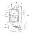
図1を参照すると、燃料サプライシステム10が示される。システム10はガス発生装置12を含み、これが燃料管16およびバルブ34を介して燃料電池(図示しない)に結合されている。好ましくは、燃料管16はガス発生装置12内において出発し、バルブ34はその側壁21bに配される。燃料管16は好ましくは可撓性のチューブであり、その長さはガス派生装置12の長さより若干短い。
Referring to FIG. 1, a
ガス発生装置12は、側壁内に、好ましくは3つの個別の室部、すなわち、流体燃料成分貯蔵部44、反応室部18、および中空部45を有し、反応室部18は、貯蔵部44および中空部45の間に封止されつつかつ滑動可能に配置される。貯蔵部44は、好ましくは、側壁21aおよび反応室部18の第1の側壁20aの間に形成される空間である。ただし、貯蔵部44はブラダーまたは類似の流体コンテナを含んでよい。流体燃料成分22、好ましくは、水および/または添加物/触媒が、貯蔵部44内に存在する。付加的な適切な流体燃料成分および添加物がさらにここで検討される。流体燃料成分22は加圧されて良いけれども、好ましくは非加圧である。中空部45は好ましくは反応室部18と対向する側の空洞な空間である。燃料または反応物への適切な添加物/触媒は、これに限定されないが、凍結抑制剤(例えば、メタノール、エタノール、プロパノール、および他のアルコール)、触媒(例えば、塩化コバルトおよび他の既知の触媒)、pH調整剤(例えば硫酸のような酸、その他の良く知られた酸)を含む。
The
反応室部18は、好ましくは、流体非浸透性材料、例えば、ステンレス鋼またはプラスチックから製造される4つの側壁20a−dを有する。反応室部18は屈曲可能部材38により装置側壁内に封止され、これはO−リングまたはガスケットであってよい。反応室部18はバイアスバネ30により後方の装置側壁21bに結合される。バイアスバネ30は当業界で知られた任意の適切なバネでよく、反応室部18を貯蔵部44にバイアスする力を実現する。バネ30を、加圧ガスまたは液体、例えば、ブタン、プロパン、またはイソ−プロパンに置換でき、また、バネ30を用いて部分的な真空が形成されるのを再層化するときには、中空部45を雰囲気へと開放してよい。
The
反応室部18内に固体燃料成分24が配される。固体燃料成分24は、好ましくは、NaBH4のタブレットである。ただし、粒状、塊状、または手の形態の固定材料も適切である。付加的な適切な固体燃料成分はここでさらに検討される。フィラー、添加物、または他の試薬および化学薬品を固体燃料NaBH4に添加して液体反応物との接触を改善させて良い。
A
燃料管16用の連結点が反応室部18の後方側壁20cに形成される。連結点17は、単に、後方の側壁20cを通る穴でよく、好ましくは、これがその頂部の位置またはその近くに配置される。このような場合、燃料管16は好ましくは連結点17に、またはその内部に、例えば接着剤を用いて固定して取り付けられる。ただし、連結点17は、燃料管16を圧縮はめ込みできるノズルを有し、この後、オプションとして、接着剤または類似の材料で固定される。また、気体透過性、液体非透過性の膜32を連結点17の反応室部対向面の上に取り付けて良い。膜32は液体すなわち副産物が燃料管16を介して燃料電池へ搬送されるのを防止する。フィラーまたは発泡体を膜に組み合わせて採用して液体すなわち副産物を保持させて目詰まりを抑制する。膜32は当業者に知られている任意の液体非硬化性、気体透過性材料から製造してよい。そのような材料は、これに限定されないが、これに限定されないが、アルケン基を具備する撥水性材料を含む。より具体的な例は、これに限定されないが、ポリエチレン組成物、ポリテトラフルオロエチレン、ポリプロピレン、ポリグラクチン(VICRY、商標)、凍結乾燥硬膜、またはこれらの組み合わせを含む。気体透過性部材30は、多硬質部材を被覆する気体透過/液体非透過性膜であってもよい。そのような膜の例は、CELGARD(商標)およびGORE−TEX(商標)である。この発明に利用可能な他の気体透過、液体非透過性部材は、これに限定されないが、約0.1μmから約0.45μmの孔サイズのSURBENT(商標)ポリビニリデンフルオライド(PVDF)であり、これはMillipore社から入手できる。SURBENT(商標)PVDFの孔サイズは、システムから出る水の量を調整する。W.L.Gore & Associates社から入手可能な0.2μmハイドロの電子ベントタイプ材料のような材料もこの発明に使用してよい。さらに、GenPore社から入手可能な約10μmの孔サイズの0.25インチ直径のロッド、または約0.3μmの厚さの2インチ直径のディスク、およびApplied Porous Technologies社から入手可能な約10μm未満の孔サイズの焼結および/またはセラミック多硬質材料もこの発明に使用できる。さらに、Bell Labs社からのナノガラス材料も液体をフィルタするのに使用できる。ナノガラスは、ガラスの刃に類似した特別に加工したシリコン表面に電荷を印可して小さな液体滴の挙動を制御する。さらに、または代替的に、本出願人の出願の米国特許出願10/356,793に開示された気体透過、液体非透過性材料もこの発明に使用でき、その内容は参照してここに組み入れる。そのような膜32はここで検討される任意の実施例において使用可能である。
A connection point for the
流体案内バルブ26が反対の反応室部側壁20aに配される。流体案内バルブ26は、好ましくは逆止バルブであり、流体燃料成分22が貯蔵部44から反応室部18へと搬送されるのと制御する。バルブ26は当業界で知られている任意の圧力開成、一方向バルブでよく、例えば、逆止バルブ、または圧力反応膜を具備して閾値圧力に達したときに開成するバルブである。反応室部18内で、バルブ26は好ましくはノズル28を有して流体燃料成分22を南欧室部18内にまき散らす。当業者に理解されるように、バルブ26は図2に示すように省略して良い。その実施例は図1に示す実施例と他の点では同一であり、ただし、小さな直径の穴28aが圧力トリガーノズルとして作用して流体燃料成分22を燃料室部18内にまき散らす。穴28aは好ましくは室部18の底部に位置決めされ、ガスが貯蔵部44は進入するのを最小化する。代替的には、固体燃料成分24は穴28aの近傍に位置決めされ、ガスの貯蔵部44への進入を最小化する。
A
燃料電池が水素ガスを必要とすると、オン/オフまたは遮断バルブ36が図1に示すように開となる。オン/オフバルブ36は当業界で知られている任意のバルブでよく、これに限定されないが、ソレノイドバルブ、逆止バルブ、その他を含み、ユーザにより手作業で、または燃料電池を制御するコントローラによって開成してよい。ガスを発生させて燃料電池用の燃料として使用させるために、流体燃料成分22が反応室部18に搬送されて固体燃料成分24と反応する。ガス発生装置12はこれを自動的に行なう。バネ30が反応室部18を定常的な力Fで貯蔵部44に向けて押す。力Fは、貯蔵部44内の静水圧HPと組合わさって、全貯蔵部圧力P22をバルブ26の貯蔵部44の側に形成する。オン/オフバルブ36が開となっている間、反応室部18内の反応室部の圧力P18は、ガスが生成され、その後、燃料かん16を通じて搬送される際に、動的に高から低に循環する。全貯蔵部圧力P22が反応室部の圧力P18より大きいときに、バルブ26は開となり、流体燃料成分が反応室部18へと流れ、これが側壁21aへと移動する。全貯蔵部圧力P22と反応室部の圧力P18との間の差分がバルブ26のトリガー点を下回ると、バルブ26が閉となり、反応室部18が移動するのを停止し、その間、その内部にガスが累積される。反応室部の圧力P18がトリガー圧力TPに至ると、燃料バルブ34が開となり、燃料ガスが反応室部18から流れだし始める。十分な燃料ガスが反応室部18から搬出されると、燃料バルブ26が開となり付加的な流体燃料成分22が反応室部18に流入し、この間、ガスは依然として反応室部18から燃料管16を通じて搬出される。最終的に、反応室部の圧力P18が落ち込んで、燃料搬送バルブ34を開に保持するトリガー圧力TPを下回る。これにより、燃料ガスを反応室部18内に累積することが可能となり、最終的に流体搬送バルブ26を閉にする。このサイクルは、以下の表1にまとめられる。

図3は、ガス発生装置212を有する燃料サプライ210の他の実施例を示し、この図において、流体燃料成分222は先に検討した流体燃料成分22と類似であり、これが貯蔵部2442内に保持され、反応室部218へ搬送され、この反応室部218は先に検討した固体燃料成分24と類似の固体燃料成分224を内包する。この実施例では、反応室部218が3つの側壁220a−cから形成される。反応室部218の底部は固体燃料キャリア225によって封止され、これは側壁220b、220cの間のぴったりとフィットしてスライド可能である。固体燃料成分225は屈曲可能部材238によって開口中に封止される。これはO−リング、ガスケット等であってよい。代替的には、固体燃料キャリア225はそれ自体が屈曲可能な適切な封止材料から製造されて良く、ただし、キャリア225は好ましくは堅固な材料、例えば、ステンレス鋼またはプラスチックから製造される。キャリア225は固体燃料成分224、例えばタブレットまたは粒状の水素化ホウ素ナトリウムが満たされる開口コンテナ部分を有する。
FIG. 3 shows another embodiment of a
キャリア225はバイアスバネ230によって反応室部218へとバイアスされ、このバネは当業界で知られている任意のタイプのバネで良い。バイアスバネ230はベース231、例えば燃料サプライ210、燃料電池、または他の同様の基本骨格の側壁に固定して実装されており、バイアスバネ230はキャリア225に定常的な力を与える。
The
キャリア225の底部にはクランクアーム242が固定して結合されている。クランクアーム242はキャリア225の底部から伸び、貯蔵部244の封止開口を通り、貯蔵部244および反応室部218の境界の上に位置するストッパ240として、または当該境界に形成された流体伝送穴226として終端する。クランクアーム242は流体燃料成分222と反応しない堅固な材料から製造して良いけれども、ストッパ240は好ましくは屈曲可能材料、例えばゴムまたはシリコーンの外部コーティングを有し、穴226を封止可能である。
A
流体搬送穴226が上部側壁220aを通じて流体燃料成分貯蔵部244を反応室部218に結合する。先に図1を参照して検討した実施例と同様に、反応室部218へと入る流体搬送穴226の端部が好ましくはノズル228を構成し、流体搬送穴226を通過するどのような流体燃料成分も反応室部218内にまき散らされるようになっている。また燃料搬送バルブ234が上方の側壁220aに設けられ、これが反応室部を燃料管216に結合する。先に検討したバルブ34と同様に、燃料伝送バルブ234は好ましくは圧力トリガーバルブ、例えば逆止バルブであり、オプションとして、気体透過性、液体非透過性の膜232により被覆されており、これは当業界で知られている任意のそのような膜で良い。
A
図1を参照して先に検討した実施例と同様に、ガス発生装置212は好ましくは装置212内部の圧力および力のバランスにより自動的に制御され循環させられる。反応室部の圧力P218は反応室部218内における燃料ガスの発生、および燃料ガスの燃料伝送バルブ234を通じた燃料電池(図示しない)への伝送に起因して動的に変化する。バネ230は定常的な力Fをキャリア225に対して上方向に加える。P218からの力がFより大きいと、キャリア225が下方に押されて、クランクアーム242を同様に可能に移動させる。最終的に、キャリア225が圧力P218に起因して十分に移動してストッバ240を押し込み、これにより流体燃料成分の反応室部218への流入が遮断される。燃料伝送バルブ234はP218がトリガー圧力TPより大きいときのみ開となる。
Similar to the embodiment discussed above with reference to FIG. 1, the
好ましくは、反応室部218は燃料または不活性ガスで充填されてキャリア225の所期状態が下方位置であり、バネ30が圧縮されている。代替的には、ユーザが手作業でストッパ240を既知の機械手段(例えば、引っ張りタブ、スライド等)により封止解除してよく、また、ストッパ240は念ン両電池に結合されるときに自動的に除去され、所期状態を不必要にする。
Preferably, the
1実施例において、流体燃料成分222はブラダー(図示しない)にストアされ、また、貯蔵部244は、加圧ガス、液化ガス、圧縮発泡体または荷重バネにより加圧され、貯蔵部244がどのような配向であっても、流体成分222が貯蔵部244から出ることが可能になっている。
In one embodiment, the
また、好ましくは、P218がバルブ234のトリガー圧力TPより大きい。燃料電池に結合されたとき、ガスは反応室部218から搬送され、P218を減少させる。最終的に、十分なガスが搬送されて、バネからの力FがP218からの力に打ち勝つようになり、キャリア225を上方へ押して、この結果、クランクアーム242を介してストッパ240を流体伝送穴226から外す。そして流体222がノズル228を通じて反応室部218へ散布される。ただし、ガスは、P218が落ちてTPを下回るまで、バルブ234を通じて反応室部218から搬送され続ける。バルブが閉になると、反応室部218内の圧力が、P218からの力がバネ230からの力に打ち勝つまで、再び形成されていき、ストッパ240が再び流体搬送穴226に栓をする。このサイクルは表2にまとめられている。
反応室部218の圧力を制御する他の手法は、図3に示すように第2の燃料電池214’を配置することである。第2の燃料電池214’は、遮断バルブ236が閉じているときに、過剰な水素を消費して圧力P218を最小化する。図示のとおり、第2の燃料電池214’は側壁220b上に配置されアノード211側を反応室部218に対面させ、水素ガスと接触させ、カソード209側を雰囲気空気側に対面させ酸素と接触させる。好ましくは、可動カバーゲート213が設けられ、水素発生装置が作動中にカソード側をカバーさせて、燃料電池214’に空気が到達せず、主燃料電池(図示しない)により必要とされるときに、第2の燃料電池214’により水素が無駄に消費されないようになっている。ユーザまたはコントローラがバルブ236を開にすると、ゲート213が動かされて第2の燃料電池214’をカバーする。ユーザまたはコントローラがバルブ236を閉にすると(または圧力P218が閾値レベルを上回ると)、ゲート213が動かされて空気がカソードに接触可能となり、過剰な水素を消費する。電気エネルギ消費装置、例えば抵抗器215、発光ダイオード、または電気消費および/または電気消散回路が、模式的に示されるように設けられて、燃料電池214’により生成される電気を消費する。第2の燃料電池214’およびカバー213はこの発明の実施例のいずれにも使用できる。
Another technique for controlling the pressure in the
図4は図3を参照して先に示し検討したものと類似なガス発生装置212を示す。ただし、この実施例では、キャリア225の底部に直接に結合されているクランクアームに代えて、軸247をヒンジによりキャリア225の底部およびクランクホイール246に結合している。バイアスバネ230がクランクホイール246とその一端で固定して取り付けられ、他端で固体ベース231に固定して取り付けられている。バイアスバネ230は定常的な力Fを実現し、この力がクランクホイール246を時計回り方向に押す傾向がある。
FIG. 4 shows a
クランクアーム242は、クランクホイール246の下側端で当該クランクホイール246に固定して取り付けられる。クランクアーム242の上側端はヒンジにより連結点239でチューブ241に結合され、これはスライド可能なストッパ240を内包する。チューブ241の他端は流体伝送穴226の上方でヒンジによりアクセス点237に取り付けられる。ストッパ240がチューブ241内で容易に移動でき、穴226に栓をすることができる範囲で、ストッパ240の材料または形状を任意にしてよい。
The
クランクホイール246が回転すると、クランクアーム242が垂直面において移動する。クランクホイール246が時計回りに回転すると、クランクアーム242がベース231に向かって下方に移動する。このようにクランクアーム242が下方に移動すると、チューブ241が引かれて、連結点239がアクセス点237の下側に位置決めされる。チューブ241がこの態様で配向されると、ストッパ240が連結点239方向へスライドして穴226の栓を外す。クランクホイール246が反時計回り方向に回転すると、クランクアーム242が上方向へ移動して、基部231から離れる。チューブ241は再び傾斜されて連結点239がアクセス点237の上側に位置決めされる。チューブ241がこの態様で配向されると、ストッパ240がアクセス点237へとスライドして穴226の栓をする。
As the
図3に示される実施例と同様に、このプロセスは好ましくはガス発生装置212内の圧力および力のバランスにより自動的に制御される。例えば、反応室部218は好ましくは初期状態では充填状態であり、反応室部218内のP218に起因する力がキャリア225を下方にかなり十分に押して、クランクアーム242がチューブ241を傾斜させてストッパ240をアクセス点237方向へスライドさせて穴226を塞ぐようになっている。また、P218がTPを上回っており、そのため燃料電池に結合したときにバルブ234が開であり、燃料ガスが反応室部218から流れ出す。この時点で、反応室部218内のガスの発生は遅く、最終的に、P218を減少させるのと停止させる。P218は、最終的に、P218からの力がもはやFに打ち勝つのに十分でなくなる点へと減少し、これがクランクホイール246を時計回りに回転させる。この動きにより、チューブ241がクランクアーム242を介して傾斜させられ、ストッパ240を連結点239へとスライドさせ、燃料伝送穴226の栓を外し、これにより、流体燃料成分222がノズル228を通じて反応室部218へと流れていく。ガスが再び燃料室部218内で生成される。ガスは燃料室部218からバルブ234を介して好ましくは反応室部218内でガスが生成続けられる速度よりも遅い速度で除去され、P218が成長する。P218がTPを下回っていると、バルブ234が閉であり、これによりガスが反応室部218内で累積可能である。この圧力および力のサイクルは表3に求められる。
図5は側壁320により形成される反応室部318を具備するさらに他のガス発生装置312を示し、これは図1−4を参照して先に説明したものと類似している。燃料搬送バルブ334、例えば逆止バルブは側壁320の1つを横切り反応室部318内に形成された燃料ガスをそれを通じて燃料管316へと通過させることが可能であり、これは図3および4を参照して先に説明した燃料管と類似である。
FIG. 5 shows yet another
流体搬搬送チューブ部350は側壁、好ましくは上側側壁を通じて反応室部318へ入る。流体搬送チューブはその一端で貯蔵部(図示しない)に結合され、貯蔵部は流体燃料成分を貯蔵する。流体燃料成分は好ましくは上述した流体燃料成分と類似である。
The fluid carrying
流体搬送チューブ350は反応室部318へと伸びる。流体搬送チューブ350の長さ方向に沿ってその先端に向かって、いくつかの流れチャンネル穴352が形成される。流体燃料成分は流体搬送チューブ350を通じて搬送され、流体燃料成分が流れチャンネル穴352から流れ出すことが可能になっている。
The
固体燃料成分324と、液体燃料成分を吸収し固体燃料成分を通じて引き上げる材料354とからなるカバーが流れチャンネル穴352を被覆している。好ましくは、固体燃料成分324は粒状形態であり液体燃料成分がそれを容易に通過できるようになっている。好ましくは、材料354は液体を吸収できるけれども、これは当該材料を通じてガスが通過できるようにしている。このような材料の一例は、ポリアクリレートナトリウム結晶を含有する紙製の綿毛であり、そのような材料はおむつに広く使用されている。他の例は、これに限定されないが、フィラーおよび発泡体を含む。一例において、図6に示すように、固体燃料成分のいくつかの層324a、324bおよび材料354a、354bが流体搬送チューブ350の周りに券回されている。ただし、1層程度を採用しても良い。流体燃料成分が固体燃料成分を通じて引かれるときに、燃料ガスが生成されて材料354を通じて反応室部318へと進む。さらに、流体がフィラーまたは発泡体まず接触し、この後、毛細管現象により固体燃料へと搬送される。
Covering the
ポリアクリレートナトリウムの結晶が水とともにゲルを形成し、この水ゲルが金属水素化物と反応し、これは本出願人の2006年3月15日出願の連続番号60/782,632の米国特許出願「燃料電池用の燃料組成物およびこれを利用したガス発生器」に示されるとおりである。’632出願は参照してここに組み入れる。 Crystals of sodium polyacrylate form a gel with water that reacts with the metal hydride, which is a serial number 60 / 782,632 application filed on March 15, 2006 by the applicant, As shown in “Fuel composition for fuel cell and gas generator using the same”. The '632 application is incorporated herein by reference.
流体制御バルブ326が好ましくは燃料搬送チューブ350内に配されて、流体燃料成分の流れチャンネル352への流れを制御する。流体制御バルブ326は好ましくは圧力トリガーのバルブであり、これは反応室部318内の圧力P318に応じて開成または閉成される。圧力搬送チューブ356により、反応室部318内で生成された燃料ガスの一部が流体制御バルブに露呈するのが可能になる。P318が流体制御バルブ326のトリガー圧力より大きいと、流体制御バルブ326が閉となり、流体燃料成分の流体伝送チューブ350を通じた流れが遮断される。P318が落ち込んで流体制御バルブ326のトリガー圧力を下回ると、流体制御バルブ326が開となり、より多くの流体燃料成分が流体伝送チューブ350へ流れることが可能になる。
A
同様に、燃料伝送バルブ334の動作もP318に制御される。P318が燃料制御バルブ334のトリガー圧力より大きいと、燃料制御バルブ334が開となり、燃料ガスが燃料管316を通り燃料電池に流れることが可能になる。P318が落ち込んで燃料制御バルブ334のトリガー圧力を下回ると、燃料制御バルブ326が閉となり、反応室部内でのガス圧の成長が可能となる。先に検討した実施例と同様に、反応室部は好ましくは製造時に充填状態とされ、ガスの発生を初期化できるようにする。
Similarly, the operation of the
図7および8は、燃料サプライ410のガス発生装置412のさらに他の実施例を示す。この実施例では、反応室部418が拡張可能なブラダー458により形成される。拡張可能なブラダー458は、外部から力を加えなくても、拡大および縮小可能な任意のタイプの材料から製造してよい。例えば、拡張可能なブラダー458はゴムまたはラテックスから製造された風船状の構造体であってよい。代替的には、拡張可能なブラダー458は、空のときに元の形状に復帰するように熱設定されて良いプラスチック材料、例えば、PETから製造されて良い。
7 and 8 show yet another embodiment of the
拡張可能なブラダー458は、ガス発生装置412の中央近くに、サポート460上でぶら下げられている。拡張可能なブラダー458は、サポート460から伸びているケージ462を封止状態で包囲し、ケージ462は固体燃料成分、例えば水素化ホウ素ナトリウムで満たされている。好ましくは、固体燃料成分は粒状であるけれども、固体タブレットまたは小塊であってもよい。ケージ462は固体燃料成分および液体燃料成分422と不活性な任意の材料から製造されて良く、当該液体燃料成分422も拡張可能なブラダー458内に配される。例えば、ケージ462はステンレス鋼またはプラスチックから製造されて良い。穴464がケージ462に形成され液体燃料成分422が固体燃料成分462と接触可能になっている。液体燃料成分422は先の実施例で検討した液体燃料成分と類似である。
An
拡張可能なブラダー458の第2の端部は燃料管416に結合され、これが、反応室部418内で生成されたガスを燃料電池へ運ぶように構成されている。燃料管416は、図3−6に示される実施例を参照して先に検討した燃料管と類似である。燃料搬送バルブ434は、好ましくは、逆止バルブのような圧力トリガーバルブであり、燃料ガスの反応室部418からの流れだしを制御するように構成されている。
The second end of the
動作においては、拡張可能なブラダー458が当初押しつぶされた行動であり、これは図7に示すようなものである。押しつぶされているときに、液体燃料成分422はケージ462と接触している。そのため、液体燃料成分422は穴464を介して流れて固体燃料成分と反応することが可能である。燃料ガス、例えば水素が生成される。燃料ガスが反応室部418内に累積されると、拡張可能なブラダー458が拡大する。反応室部418内のRCPが燃料搬送バルブ434のトリガー圧力TPを上回ると、燃料搬送バルブ434が開となって反応室部418から燃料電池へと燃料ガスを搬送可能にする。拡張可能なブラダー458が、例えば図8に示すように、限界サイズに至ると、液体燃料成分422のすべてが拡張可能なブラダー458の底部に収集されて、ケージ462内の固定燃料成分ともやや接触しなくなる。このため、十分なガスが反応室部418から燃料電池へ搬送され終わるまで、液体燃料成分と固体燃料成分との間でさらなる反王が起こることがない。オプションとして一方向開放バルブ430を含ませて、例えば、燃料ガスを雰囲気中へ排出することにより、拡張可能なブラダー458の過剰な圧縮を阻止して良い。当業者に理解されるように、ガス発生装置412は任意の配向であって良い。
In operation, the
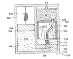
図9および10は、燃料管516を介して燃料電池(図示しない)に結合されるように適合化された燃料サプライ510のガス発生装置512のさらに他の実施例を示す。ガス発生装置512が、側壁520内に形成された2つの室部、すなわち、加圧液体燃料成分室部544および反応室部518を有する。側壁520は、加圧液体燃料成分室部544内に内包された液体燃料成分522、例えば、水または添加物含有の水や、反応室部518内に内包された固体燃料成分524、例えば水素化ホウ素ナトリウムに対して不活性な材料から、好ましくは形成される。流体搬送管588は加圧液体燃料成分室部544および反応室部518を連結する。先に検討した実施例と同様に、燃料搬送バルブ534、好ましくは逆止バルブのような圧力トリガーバルブや、バルブ534の下流のオン/オフバルブ36(図示しない)により、反応室部518から燃料管516さらには燃料電池への搬送が可能になる。
FIGS. 9 and 10 show yet another embodiment of a
バネ荷重ピストン584が、封止状態、かつスライド可能に、当初では、過ある液体燃料成分室部544の頂部またはその近くに配される。好ましくは、ピストン584は潤滑封止材料586、例えばワセリンで封止されるけれども、他の封止部品、例えばO−リングまたはガスケットを採用して良い。バイアスバネ530は連続的な力Fをピストン584に加え液体燃料成分522が定常的に反応室部518側に押されるようになっている。先に検討して場合と同様に、バネ530は加圧材料、例えば液体/気体炭化水素、具体的にはブタン、プロパン、またはイソプロパンで置換できる。
A spring-loaded
可撓性のある流体チューブ582が、以下に検討するように、流体伝送管588と流体連通され、反応室部518内でノズルまたは開口528で終端している。流体燃料成分522は可撓性のある流体チューブ582を通じて選択的に反応室部518へと至る。可撓性のある流体チューブ582はメッシュピストン580を通り抜け、あるいは、これと接触する。メッシュピストン580はバイアスバネ572により燃料成分524へとバイアスされている。バイアスバネ572は連続的に力をメッシュピストン580に付与してこれを燃料成分524内へ、燃料管516側にバイアスする。メッシュピストン580は固体燃料成分524とバネ572により接触し続け、この固体燃料成分524は好ましくはピストン580のメッシュを通過しないほど大きな粒から形成される。ただし、流体燃料成分522がノズル528を通じて反応室部518へ流入して固体燃料524と反応するとき、図10に示すように、燃料ガスおよびスラリー590、例えば、液状ホウ酸塩が形成される。スラリー590はピストン580のメッシュを通じて流れてメッシュピストン580の下に累積可能である。そして、バネ572は連続してメッシュピストン580を未反応部分の固体燃料成分524中へと押し込んでいく。このため、ノズル528から流出する流体燃料成分は、比較的副産物を含まない、新たな固体燃料成分524と連続して接触する。
A
先に検討した実施例と同様に、ガス発生装置512も自己制御される。メッシュピストン580の下側に配置された膜574、オプションのバネ573、およびバネ526反応室部518内の圧力P518に露呈される。流体管575は膜574を通り抜けて形成され、流体管588を可撓性のあるチューブ582に流体的に結合する。反応室部518内で圧力が成長すると、最終的に、これが膜574のトリガー圧力TPに至る。これが膜574のトリガー圧力に到達すると、膜574は曲がってバルブ526を閉にし(図示しない)、これにより流体燃料成分の反応室部518への流れを遮断する。燃料ガスは、P518が減少してTPを下回るまで、燃料伝送バルブから流れだし、下回った時点で、膜574が再び開となり、付加的な液体燃料成分522を反応室部518へ案内することにより、燃料ガスの生成が開始される。バネ573は膜574が開位置に復帰するのを支援する。バルブ526は、膜574がP518、例えば、逆止バルブに対して作用して開および閉となることができる任意のバルブであってよい。
Similar to the previously discussed embodiment, the
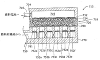
図11は、燃料管616を介して燃料電池(図示しない)に結合されるように適合化されたガス発生装置612のさらに他の実施例を示す。この実施例において、反応室部618は大量の固体燃料成分624を含み、これは好ましくは粒状または紛状の形態である。反応室部618は2つの対抗する側壁620を有し、これらは、先に検討したものと類似の固体の非反応性の材料から製造される。ただし、反応室部618の底部680は好ましくは多孔質の非反応性の材料、例えば、メッシュまたは穴を配した材料からなるシートから製造される。ファイバーグラスは底部680に適した多くの材料のうちの1つである。底部680の穴の寸法は、固体燃料成分624の個々の粒が当該穴を通過しないようなものとなっている。
FIG. 11 shows yet another embodiment of a
反応室部618の頂部632は好ましくは気体透過性、液体非透過性の膜、例えば、図1を参照して先に説明した膜32から製造される。適切な材料の例はCELGARD(商標)およびGORE−TEX(商標)を含む。燃料ガス貯蔵部619が頂部の膜632に隣接して配置されて反応室部618内で生成され膜632を通過してくる燃料ガスを収容する。バルブ634、例えば逆止バルブが燃料ガス貯蔵部619から燃料管6196への燃料ガスの流出を制御する。バルブ634は当業界で知られている任意のタイプのバルブであってよく、図1を参照して先に説明したバルブ34とデザインおよび機能の点で類似している。
The top 632 of the
マニホールド679が底部680に隣接して配置される。好ましくは、いくつかの流れチャンネル652a−fがマニホールド679内に形成される。当業者に理解されるように、流れチャンネルの数は、燃料のタイプ、燃料電池のタイプ、および燃料電池により駆動されるデバイスを含むファクタに左右されて幅広く変化する。好ましくは、流れチャンネルの数は2から100であり、より好ましくは、約50から約75である。
A manifold 679 is disposed adjacent to the bottom 680. Preferably,
流れチャンネル652a−fは流体的に供給チューブ650に結合され、これを通じて流体燃料成分(図示しない)が貯蔵部(図示しない)から供給される。供給チューブ650を介する燃料の流れは、好ましくは、コントローラにより制御され、このコントローラが付加的な燃料が必要なことを通知して流体貯蔵部および供給チューブ650の間に配されたバルブ(図示しない)を開にする。代替的には、ユーザがスイッチをトリガーしてそのようなバルブをカイトして流れを開始させて良い。マニホールド679は、いずれの所与の時点でも、流れチャンネル652a−fの1つのみが供給チューブ650から流体燃料成分を受け取り固体燃料成分624の異なる領域が順次に反応されるように構成されている。換言すると、流体燃料成分が流れチャンネル652aを流れるのならば、流れチャンネル652b−fは流体燃料成分を含まず、使用されていない流れチャンネル652b−fの上に配置されている固体燃料成分624は乾燥したままで非反応である。
この一連の流れチャンネル652a−fの使用は、好ましくは、部分的には、各流れチャンネルの径を他の流れチャンネルと異ならせることにより実現される。好ましくは、流れチャンネル652aは最も大きな径をもち、各流れチャンネルが流れの方向に順次に少しずつ径を小さくする。換言すれば、流れチャンネル652bの径は流れチャンネル652cの径より大きく、以下同様である。当業界で知られているように、流体は最も抵抗の小さい経路を流れる。下流側に位置するつぎの流れチャンネルのより狭い径により、基本的に、流体の流れが制約されるので、流体は最も大きな利用可能なチャンネルを通じた経路を流れる傾向がある。例えば、流れチャンネル652aまたは流れチャンネル652bを通る流路がある場合には、ほとんどの流体は流れチャンネル652aを通る。
The use of this series of
流体が最も大きな利用可能なチャンネルを通じて流れるというこの傾向は、オプションとして、供給チューブ652を段階的な構造に形成することにより、助長され、この場合、供給チューブ650の径は、つぎに継続する流れチャンネル652に至る直前で若干増大する。例えば、供給チューブ650は、比較的幅のある流れチャンネル652aの近傍で比較的狭く、供給チューブ650中の流体は、供給チューブ65に沿って流れ続けるのでなく流れチャンネル652aは入っていく傾向がある。
This tendency for fluid to flow through the largest available channel is optionally facilitated by forming the supply tube 652 in a stepped structure, where the diameter of the
流体燃料成分が反応室部618へ流れチャンネル652aを通じて流れるときに、流体燃料成分は固体燃料624と反応する。例えば、固体燃料成分624が水素化ホウ素ナトリウムであり、流体燃料成分が水またはドーピングした水であると、水素ガスおよび液状ホウ酸塩のスラリーが生成される。スラリーが流れチャンネル652aの口部から除去されないなら、スラリーがコンクリートのように硬くなる傾向がある。この硬化スラリーが最終的に完全に流れチャンネル652aを塞ぐ。流れチャンネル652aがブロックされると、供給チューブ650中の流体は次の利用可能な経路、すなわち流れチャンネル652bへ流れる。流体の幾分かは流れチャンネル652bを越えて流れ縷々けれども、この流量は、流れチャンネル652bも硬化スラリーによりふさがれるまで、残りの流れチャンネル652c−fのいずれにも流れ入るには十分でないと考えられる。このプロセスはすべての流れチャンネル652a−fがふさがれ、および/または、すべての固定燃料成分624が消費されるまで継続する。
The fluid fuel component reacts with the
オプションとして、第2のメッシュ681を流れチャンネル652a−fのそれぞれの入口に配置する。第2のメッシュ681の孔サイズは極めて小さく、流体は通過するけれども、反応室部618を抜け出すどのようなスラリーも捕捉して流体燃料成分を汚染したり、または供給チューブ650を塞がないようになっている。当業者に理解されるように、流れチャンネル652の他の水力パラメータを変更して流体が特定の流路を選択する傾向を操作して良く、例えば、流れチャンネルの高さを操作してよく、この場合、下流の流れチャンネルが茶園こうする流れチャンネルより順番に高くなる。水力パラメータの任意の組み合わせを採用して良い。
Optionally, a
図12を参照すると、順番に流れチャンネル752a−fをアクセスすることを可能にするガス発生装置712の他の構造が示される。この実施例は図11の実施例と類似しており、この実施例では、下流の流れチャンネル752b−cのアクセスが一連のバルブ753a−eにより制御される。バルブ753a−eは好ましくは圧縮トリガーのバルブ、例えば逆止バルブまたは隔膜バルブである。流体が供給チューブ750を通って流れるとき、すべてのバルブ753a−eが閉とされて流体が流れチャンネル752aに流入するようになす。先に説明したように、流れチャンネル752aは硬化スラリーによりふさがれる。流れチャンネル753aがブロックされたとき、供給チューブ750内の流体の圧力が第1のバルブ752aを開にするまで、増大する。その時点で流体は流れチャンネル752bへ流れる。好ましくは、バルブ753aが開になると、例えば、内部の壊れ易い部材を具備することにより、新たな流路が開となって流れの圧力が典型的には減少しても、これは閉に復帰しない。当業者が理解するように、各バルブ753a−eはオプションとして壊れ易い膜により置換されて良い。流れチャンネル752a−fがふさがれ、バルブが開となり、壊れ易い膜が破壊されるというこのプロセスは、流れチャンネル752a−fがすべてふさがれ、および/または、すべての固体燃料成分724が消費されるまで継続される。
Referring to FIG. 12, another structure of
図13を参照すると、さらに他のガス発生装置812が示される。先の実施例と同様に、反応室部818はハウジング820内に含まれる。ハウジング820はガス発生反応を包み込むことが可能な任意の材料から製造されて良く、好ましくは、反応に対して不活性な材料、例えばプラスチックまたはステンレス鋼から製造されて良い。ハウジング820の一端は、ストッパ840により封止されている。ストッパ840は、ハウジング820を封止して、反応時に生成されるガスや液体燃料成分822が逃げ出すのを阻止できる任意の材料から製造する。ハウジング820の他端はバルブ834を含み、燃料電池(図示しない)、または、燃料電池へ向かう燃料管(図示しない)に向かっている。バルブ834はここで検討した他のバルブと類似であり、好ましくは逆止バルブまたは遮断バルブである。
Referring to FIG. 13, yet another
固体燃料成分824、例えば水素化ホウ素ナトリウムがハウジング820の側壁に並んでいる。好ましくは、固体燃料成分824は粉状または粒状の形態であるけれども、固体燃料成分824はタブレットの形態でも良い。固体燃料成分824が粉状または粒状の形態で提供されるならば、スクリーンまたはメッシュ827を固体燃料成分824の上に設ける。メッシュ827の孔サイズは、液体燃料成分824が固体燃料成分824にアクセス可能にするのに十分な程小さい。ただし、固体燃料成分824は保持する。また、固体燃料成分824は、分割部材825によりいくつかの室部に分割されて良い。分割部材825は各室部を封止して液体燃料成分822が1の分割部材から隣の分割部材に進入できないようにできる材料から製造される。オプションとして、固体燃料成分824の粒を持続放出型の材料でカプセル化してよく、この場合、異なる持続放出型材料、例えば、厚さが異なる水溶解材料を採用する。このため、固体燃料成分824のいくつかは早期に使用され、残りの固体燃料成分824は時間的に遅れた時点での使用に留保できる。
A
液体燃料材料822は好ましくは水または水ベースのゲルであり、これは先に検討した液体燃料成分と類似である。水ベースのゲルは、水に親水性の化合物、例えばポリアクリレートナトリウム結晶を混合させて製造できる。水ゲルは先に検討し’632特許出願に開示されており、すでに参照してここに組みこんでいる。液体燃料成分822はブラダー844内に含まれる。ブラダー844は屈曲可能な材料により製造され、これは実質的に液体燃料成分822と不活性な材料であり、例えば、ゴム、シリコーン、または薄肉のプラスチックである。好ましくは、ブラダー844は複数の襞を具備するように構成され、ブラダー844が容易に、かつ制御された態様でつぶれるようになっている。
The
ブラダー844には流体管882が流体的に結合され、これがノズル828で終端する。流体管882およびノズル828は流路を形成して液体燃料成分822を固体燃料成分824の特性のセクション、例えば、1の室部に方向づける。好ましくは、流体管882およびノズル828は比較的小さな口径の部品であり、ほんの少ない量の液体燃料成分822しか任意の所定の時点で消費されない。図13においてはノズル828は単一の点のノズルとして示されているけれども、図13Aに示すように、流体管882’に結合されているノズル828’は複数の出口を含んで良く、これは、例えば、ブラダー844に流体的に結合された、複数の同時的な流体出口として働く複数の穴を具備する、空洞のリングであってよい。
A
バネ830がブラダー844の端部に、流体管882およびノズル828と対向して配置されている。バネ830は好ましくは定荷重バネである。バネ830は一定の引っ張り力を実現できる任意のタイプのバネ、例えば、板バネまたはゼンマイバネであってよい。好ましくは、バネ830は液体燃料成分822に対して実質的に不活性な材料、例えばプラスチックまたはステンレス鋼から製造される。バネ830の一端はブラダー844の一端を通って伸びブラダー844の他端に流体管882の位置またはその近くで固定して結合される。このため、バネ830はブラダー844のノズル端をストッパ840へ引っ張る。バネ830の引っ張りにより、ブラダー844が絞られ、これによって、液体燃料成分822を流体管882を通じてノズル828から押し出して固体燃料成分822へと案内する。反応室部818内でガスが発生する。反応室部818内の圧力が閾値レベルに到達すると、バルブ834が開となり、ガスを燃料電池へと搬送可能にする。代替的には、バルブ834が遮断バルブであり、ユーザまたはコントローラにより開にできる。ブラダー844が空になると、ノズル828が以下にさらに検討するようにストッパ840へ移動し、液体燃料成分822が確実に固体燃料成分824の新たなセクションに案内されるようにする。
A
バネ830がブラダー844を引くときに、液体燃料成分822が固体燃料成分824に案内され、これによりガスが連続して生成される。ただし、中断させることなしにガスを生成することが望まれなくてもよい。例えば、遮断バルブ例えばバルブ834が閉のときに水素ガスの発生を停止させなくてはならない。そのようなバルブは、例えば、ユーザにより、または燃料電池による燃料の使用を監視するコントローラを介して、手作業でトリガーされてよい。そのような遮断バルブが閉のときに、ガスはハウジング820から燃料電池へと搬送できない。そのため、生成ガスからの圧力が反応室部818内またはハウジング820内で成長する。圧力は例えば圧力解放逆止バルブ(図示しない)または第2の燃料電池により開放してよく、これは先に検討し、ハウジング820の側壁内に配置されるけれども、ガスの生成を遮断バルブの閉止の後に停止すべきである。
When the
そのため、ガス発生装置812に、好ましくは、バネ830を巻くのを停止するように構成された圧力反応スリーブ832が設けられる。圧力反応スリーブ832がストッパ840に隣接して設けられ、少なくともバネ830に隣接する。圧力反応スリーブ832は好ましくはハウジング820内で圧力により容易に平行移動させられる堅固な材料、例えば、プラスチック、金属、その他から製造される。圧力反応スリーブ832はストッパ840と離間してハウジング820内でスライド可能に配されてギャップ831を生成して圧力反応スリーブ832が自由にハウジング820内でギャップ831を出入りするように自由に平行移動するようになっている。圧力形成バルブ832はバネ829によりストッパ840から離れるようにバイアスされ、これは当業界で知られている任意のタイプのバネ、例えばコイル圧縮バネまたは液体炭化水素であってよい。
To this end, the
反応室部818内の圧力が閾値に到達すると、圧力反応スリーブ832をバイアスしてストッパから遠ざけている、バネ829により付与される圧力が、打ち負かされ、圧力反応スリーブ832がストッパ832へと平行移動する。この移動の際、圧力反応スリーブ832はバネ830を絞り、これによりバネ830がさらに巻き取られるのを阻止する。このようにして、バネ830はもはやブラダー844を引くことができず、さらなる液体燃料成分がブラダー844から追い出すことがない。ガスが再びハウジング820から開放されて圧力が下がって閾値レベルを下回ると、バネ829は拡大して、圧力反応スリーブ832が平行移動して元の位置に戻って、これにより、バネ830を開放させる。バネ830は再びブラダー844のノズル端を引いて、付加的なガスを生成させてよい。
When the pressure in the
さらに他のガス発生装置912を図14に示す。ガス発生装置912は、先に示し検討した他のガス発生装置用のハウジングと類似なハウジング920を有する。ハウジング920は、全体として、固体燃料成分924、例えば水素化ホウ素ナトリウムを包含する反応室部918と、液体燃料成分922、例えば水を内包する液体燃料成分室部944とを形成するように構成されている。当業者に理解されるように、この出願で検討される任意の固体または液体の燃料成分がこの実施例に使用して好適である。
Yet another
ハウジング920内でスライド可能に配置されるピストン980がハウジング920の内部を液体燃料室部944および反応室部918に分割する。ピストン980は、ハウジング920内に封止状態で配される。そのため、ピストン980は好ましくは液体燃料成分922、固体燃料成分924、またはそれらの間の反応により生成されたガスに対して非反応な屈曲可能材料から製造され、また、ピストン980の封止性およびそのスライド動作を助長するゲル状の材料、例えば、ワセリンにより被覆される。代替的には、図14に示すように、先に検討した屈曲材料と同様に非反応性である、任意の堅固な材料から製造されてよいけれども、少なくとも1つの封止部品938、例えば、ゴム、またはシリコーンO−リングまたはゲル状の潤滑材料、例えばワセリンを有する。輪留め981または類似の構造を反応室部918内にピストン980に隣接して設けてピストン980が値気体燃料成分室部944の方向にのみスライド可能にする。輪留め981は好ましくはプラスチックまたは金属の窪んだディスクであり、そのエッジが鋭くなって、ハウジング920の側壁を把持またはアンカー止めして凹んだ方向と反対の方向への移動を阻止するようになっている。
A
ハウジング920の一端はストッパ940により封止され、液体燃料成分室部944がストッパ940、ハウジング920、およびピストン980におり形成される。ストッパ940は、反応時に生成さえるガスまたは液体燃料成分922を逃さないようにハウジング920を封止することが可能な任意の材料、例えば、ゴム、シリコーンまたはその他から製造される。液体燃料成分922は好ましくは液体燃料成分室部944を完全に満たす。さらに、液体燃料成分922は水素または他の類似の燃料ガスで加圧されて液体燃料成分922が液体燃料成分室部944から流れだすのを助長するようになっていてよい。加圧ガスは、液体燃料成分室部944に配された弾性ブラダー内に含まれ、液体燃料成分922を液体燃料成分室部944から追い出すように拡大するようになっていてよい。オプションとして、逆止バルブまたは圧力開放バルブ(図示しない)を、液体燃料成分室部944を形成する、ハウジング920の側壁に設け、空気または他の環境ガスが液体燃料成分室部944へ案内可能にしてその内部に真空ができ、ピストン980の移動が停止されるのを阻止する。
One end of the
ハウジング920の他端は第2のストッパ935を有し、その構造および材料はストッパ940と類似である。このため、反応室部918が第2のストッパ935、ハウジング920、およびピストン940により形成される。ただし、バルブ934が第2のストッパ935に配されて燃料電池(図示しない)または燃料電池へ進む管(図示しない)への流路を形成する。バルブ934はここで検討された他のバルブと類似であり、好ましくは、反応室部918内の圧力が閾値レベルに到達したときにのみ開となるように構成された遮断バルブまたは逆止バルブである。固体燃料成分924が反応室部内で第2のストッパ935の位置または近くでハウジング920の側壁に配される。好ましくは、固体燃料成分924は、ハウジング920の側壁へ圧接、その他、接着されたタブレット形態でリング状の構造を形成する。代替的には、固体燃料成分924は粒状または粉状の形態でありメッシュまたはスクリーンによりハウジング920の側壁に固定して保持され、メッシュまたはスクリーンの穴サイズは、固体燃料成分924の粒が穴を通過しないけれども、液体燃料成分922がそこを通り抜けて固体燃料成分924と反応できるように選択される。
The other end of the
流体搬送チューブ982がピストン980を通って設けられ、液体燃料成分室部944を反応室部918と流体的に結合する。流体搬送チューブ982は液体燃料成分022を固体燃料成分924へ搬送できる任意のタイプのチューブまたはパイプであってよい。ただし、流体搬送チューブ982は、好ましくは、液体燃料成分922、固体燃料成分924、およびそれらの反応により生成されたガスに対して実質的に不活性な材料から製造された小さな穴の、堅固なチューブである。好ましくは、流体搬送チューブ982の穴は約0.001インチおよび0.01インチの間であり、さらに好ましくは流体搬送チューブ982の穴は約0.005インチである。
A
流体搬送チューブ982の長さは、ピストン980のストッパ940の方向への移動により、一滴の流体のみしか流体搬送チューブ982から固体燃料成分924へ放出されないように選択される。流体搬送チューブ982は好ましくは十分な長さを有し、当初の位置において、流体搬送チューブ982の自由端が固体燃料成分924を通ってストッパ935の位置またはその近くの点へ伸びるようになっている。このため、ピストン980が移動するとき、流体搬送チューブ982が固体燃料成分924の新鮮な供給位置へと移動される。また、代替的には、例えば、液体燃料成分922が液体燃料成分室部944内に設けられ液化炭化水素により満たされたブラダーにより加圧されるならば、ピストン980は度どうする必要がない。この場合、液化炭化水素は定圧で伸びて液体燃料成分922を液体燃料成分室部944から放出する。
The length of the
動作では、液体燃料成分922が、当初、トリガーされ、これは、例えばユーザが液体燃料成分922を加圧し、または流体搬送チューブ982を被覆しているシール(図示しない)を破いたり、除去したりする。すると、液体燃料成分922が流体搬送チューブ982を通じて反応室部へ流入し固体燃料成分状へ落ちる。液体燃料成分922および固体燃料成分924が反応して水素を発生する。反応室部918内で十分な圧力が成長すると、逆止バルブ934が開となり燃料ガスを燃料電池(図示しない)に流すことが可能となり、または、代替的には、ユーザまたはコントローラが遮断バルブを開にする。反応室部918内の圧力がさらに増加すると、反応室部の圧力P918が、最終的に、反応室部の圧力P918がピストン980をストッパ940へ押すレベルに到達する。ただし、反応室部の圧力P918がさらに増加すると、最終的に、さらなる液体燃料成分922が流体搬送チューブ982を通じて流れるのを阻止する。これは、反応室部の圧力P918が液体燃料成分室部の圧力P944より大きくなると、液体燃料成分922が圧力勾配により反応室部918に流入できないからである。換言すれば、液体燃料成分室部の圧力P944は反応室部の圧力P918より少なくとも固定量、例えばXpsiだけ大きくなくてはならない。流体伝送チューブ982は好ましくは十分に長く、Xが2psiに等しく、例えば、流体が流体伝送チューブ982を通じて流れるようになっている。例えば、反応室部からのバルブ934を通じた伝送により、反応室部の圧力P918が小さくなると、液体燃料成分922が再び流体伝送通路982を介して流れて付加的なガスが生成されてよい。換言すれば、生成された水素がガス発生装置912から十分な速度で搬出され反応室部の圧力P918が比較的地位差のマニの維持される限り、液体燃料成分922が反応室部918に搬送され続ける。
In operation, the
この発明において利用可能な燃料の例は、これに限定されないが、元素周期表のIA−IVAのグループの元素の水素化物およびその混合物、例えば、アルカリ性またはアルカリ金属水素化物、またはこれらの混合物を含む。他の化合物、例えばアルカリ金属水素物(アラネート)および水素化ホウ素アルカリ金属も採用して良い。金属水素化物のより具体的な例は、これに限定されないが、リチウム水素化物、リチウム・アルミニウム水素化物、水素化ホウ素リチウム、ナトリウム水素化物、水素化ホウ素ナトリウム、カリウム水素化物、水素化ホウ素カリウム、マグネシウム水素化物、カルシウム水素化物、およびこれらの塩および/または誘導物を含む。好ましい水素化物は、水素化ホウ素ナトリウム、水素化ホウ素マグネシウム、水素化ホウ素リチウム、および水素化ホウ素カリウムである。好ましくは、水素担持燃料はNaBH4、またはMg(BH4)2の固定形態であり、また、メタノールクラスレート化合物(MCC)はメタノールを有する固体である。固体形態において、NaBH4は水なしには加水分解せず、このためカートリッジの保管寿命を改善する。ただし、液体形態の水素担持燃料、例えば、液体のNaBH4もこの発明に採用できる。液体形態のNaBH4を採用するときには、液体形態のNaBH4を含む室部が安定剤も含む。例示的な安定剤は、これに限定されないが、金属、水酸化金属、例えば、アルカリ金属水酸化物を含んで良い。このような安定剤は、米国特許第6,683,025号に説明されており、その内容は参照してここに組み入れる。好ましくは、安定剤はNaOHである。 Examples of fuels that can be used in this invention include, but are not limited to, hydrides of elements of groups IA-IVA of the Periodic Table of Elements and mixtures thereof, such as alkaline or alkali metal hydrides, or mixtures thereof. . Other compounds such as alkali metal hydrides (alanate) and alkali metal borohydrides may also be employed. More specific examples of metal hydrides include, but are not limited to, lithium hydride, lithium aluminum hydride, lithium borohydride, sodium hydride, sodium borohydride, potassium hydride, potassium borohydride, Magnesium hydride, calcium hydride, and salts and / or derivatives thereof are included. Preferred hydrides are sodium borohydride, magnesium borohydride, lithium borohydride, and potassium borohydride. Preferably, the hydrogen-carrying fuel is a fixed form of NaBH 4 or Mg (BH 4 ) 2 and the methanol clathrate compound (MCC) is a solid with methanol. In the solid form, NaBH 4 does not hydrolyze without water, thus improving the shelf life of the cartridge. However, a liquid form of hydrogen-carrying fuel, for example, liquid NaBH 4 can also be employed in the present invention. When liquid form NaBH 4 is employed, the chamber containing liquid form NaBH 4 also contains a stabilizer. Exemplary stabilizers may include, but are not limited to, metals, metal hydroxides, such as alkali metal hydroxides. Such stabilizers are described in US Pat. No. 6,683,025, the contents of which are hereby incorporated by reference. Preferably, the stabilizer is NaOH.
固体形態の水素担持燃料は液体形態より好ましい。一般的に、固体燃料は液体燃料より有益である。なぜならば、液体燃料は固体燃料より少ないエネルギしか含まず、液体燃料は対応する固体燃料より不安定であるからである。したがって、この発明において最も好ましい燃料は粉末化または凝集粉の水素化ホウ素ナトリウムである。 A solid form of hydrogen-supported fuel is preferred over a liquid form. In general, solid fuel is more beneficial than liquid fuel. This is because liquid fuel contains less energy than solid fuel, and liquid fuel is more unstable than the corresponding solid fuel. Thus, the most preferred fuel in this invention is powdered or agglomerated sodium borohydride.
この発明によれば、液体反応物は好ましくはオプションの触媒の存在下で水素担持燃料と反応して水素を生成できる薬剤を有する。好ましくは、薬剤は、これに限定されないが、水、アルコール、および/または希釈酸を含む。最も一般的な薬剤は水である。先に、または以下の式において示すように、水は、オプションとしての触媒の存在下で、水素担持燃料、例えばNABH4と反応して水素を発生する。
X(BH4)y + 2H2O → X(BO)2 + 4H2
ただし、Xは、これに限定されないが、Na、Mg、Li、およびすべてのアルカリ金属を含み、Yは整数である。
According to this invention, the liquid reactant preferably has an agent capable of reacting with a hydrogen-supported fuel to produce hydrogen in the presence of an optional catalyst. Preferably, the drug includes, but is not limited to, water, alcohol, and / or diluted acid. The most common drug is water. As shown earlier or in the following equation, water reacts with a hydrogen-supported fuel, such as NABH 4 , to generate hydrogen in the presence of an optional catalyst.
X (BH 4 ) y + 2H 2 O → X (BO) 2 + 4H 2
However, X includes, but is not limited to, Na, Mg, Li, and all alkali metals, and Y is an integer.
反応物は溶液のpHを増加させ、または減少させるオプションの添加物を含んでも良い。反応物のpHは水素を生成する速度を決定できる。例えば、反応物のpHを減少させる添加物は、水素発生速度を大きくする。このような添加物は、これに限定されないが、酸、例えば酢酸を含む。逆に、pHを増大させる添加物は水素が殆ど生成されないレベルまで反応速度を遅くする。この発明の溶液は、7未満の任意のpHを有して良く、例えば、約1から約6までのpHであり、好ましくは、約3から約5のpHである。適切なpHのさらなる検討は本出願人の出願’572に見いだせ、これについては既に参照してここに組み入れた。 The reactants may include optional additives that increase or decrease the pH of the solution. The pH of the reactant can determine the rate at which hydrogen is produced. For example, additives that reduce the pH of the reactants increase the rate of hydrogen generation. Such additives include, but are not limited to, acids such as acetic acid. Conversely, additives that increase the pH slow the reaction rate to a level where little hydrogen is produced. The solution of this invention may have any pH of less than 7, for example, a pH of about 1 to about 6, and preferably a pH of about 3 to about 5. Further discussion of suitable pH can be found in Applicant's application '572, which has already been incorporated herein by reference.
いくつかの事例的な実施例において、反応物は、水素の発生を開始させ、および/または、反応物が反応する速度を増大させることにより水素の発生を容易にする触媒を含んでよい。これら事例的な実施例のオプションの触媒は、所望の反応を支援できるいかなる形状またはサイズを含んでよい。例えば、触媒は粉末の形態をとるほど小さくて良く、また、反応室部と同じくらいに大きくて良い。いくつかの事例的な実施例では、触媒は触媒床である。この触媒は、反応物または燃料成分の少なくとも一方が触媒に接するようになる限り、反応室部の内部に、または反応室部の近傍にあってよい。 In some exemplary embodiments, the reactants may include a catalyst that initiates hydrogen generation and / or facilitates hydrogen generation by increasing the rate at which the reactants react. The optional catalyst in these example embodiments may include any shape or size that can support the desired reaction. For example, the catalyst can be small enough to take powder form and can be as large as the reaction chamber. In some example embodiments, the catalyst is a catalyst bed. The catalyst may be inside the reaction chamber or in the vicinity of the reaction chamber as long as at least one of the reactants or fuel components comes into contact with the catalyst.
この発明の触媒は、元素の周期律表のVIIIB族からの1またはそれ以上の遷移金属を含んでよい。例えば、触媒は、遷移金属、例えば、鉄(Fe)、コバルト(Co)、ニッケル(Ni)、ルテニウム(Ru)、ロジウム(Rh)、プラチナ)Pt)、パラジウム(Pd)、オスミウム(Os)、イリジウム(Ir)を含んで良い。さらに、IB族の遷移金属、すなわち、銅(Cu)、銀(Ag)、および金(Au)、およびIIBの遷移金属、例えば、亜鉛(Zn)、カドミウム(Cd)、および水銀(Hg)をこの発明の触媒として採用しても良い。触媒の一部として採用できる、他の遷移金属は、これに限定されないが、スカンジウム(Sc)、チタン(Ti)、バナジウム(V)、クロム(Cr)、およびマンガン(Mn)を含む。この発明の触媒システムに使用して有益な遷移金属は、米国特許第5,804,329号に説明されており、その内容は参照してここに組み入れる。この発明の好ましい触媒はCoCl2である。 The catalyst of this invention may comprise one or more transition metals from group VIIIB of the periodic table of elements. For example, the catalyst may be a transition metal such as iron (Fe), cobalt (Co), nickel (Ni), ruthenium (Ru), rhodium (Rh), platinum) Pt), palladium (Pd), osmium (Os), Iridium (Ir) may be included. In addition, group IB transition metals, ie, copper (Cu), silver (Ag), and gold (Au), and IIB transition metals, such as zinc (Zn), cadmium (Cd), and mercury (Hg). You may employ | adopt as a catalyst of this invention. Other transition metals that can be employed as part of the catalyst include, but are not limited to, scandium (Sc), titanium (Ti), vanadium (V), chromium (Cr), and manganese (Mn). Useful transition metals for use in the catalyst system of the present invention are described in US Pat. No. 5,804,329, the contents of which are hereby incorporated by reference. The preferred catalyst of this invention is CoCl 2.
この発明の触媒のいくつかは一般に次の式で定義される。
MaXb
ただし、Mは遷移金属の陽イオン、Xは陰イオン、「a」および「b」は、遷移金属錯体の電荷をバランスさせるのに必要な1から6の整数である。
Some of the catalysts of this invention are generally defined by the following formula:
M a X b
Where M is a cation of a transition metal, X is an anion, and “a” and “b” are integers of 1 to 6 necessary for balancing the charge of the transition metal complex.
適切な遷移金属の陽イオンは、これに限定されないが、鉄(II)(Fe2+)、鉄(III)(Fe3+)、コバルト(Co2+)、ニッケル(II)(Ni2+)、ニッケル(III)(Ni3+)、ルテニウム(III)(Ru3+)、ルテニウム(IV)(Ru4+)、ルテニウム(V)(Ru5+)、ルテニウム(VI)(Ru6+)、ルテニウム(VIII)(Ru8+)、ロジウム(III)(Rh3+)、ロジウム(IV)(Rh4+)、ロジウム(VI)(Rh6+)、パラジウム(Pd2+)、オスミウム(III)(Os3+)、オスミウム(IV)(Os4+)、オスミウム(V)(Os5+)、オスミウム(VI)(Os6+)、オスミウム(VIII)(Os8+)、イリジウム(III)(Ir3+)、イリジウム(IV)(Ir4+)、イリジウム(VI)(Ir6+)、プラチナ(II)(Pt2+)、プラチナ(III)(Pt3+)、プラチナ(IV)(Pt4+)、プラチナ(VI)(Pt6+)、銅(I)(Cu+)、銅(II)(Cu2+)、銀(I)(Ag+)、銀(II)(Ag2+)、金(I)(Au+)、金(III)(Au3+)、亜鉛(Zn2+)、カドミウム(Cd2+)、水銀(I)(Hg+)、水銀(II)(Hg2+)、その他を含む。 Suitable transition metal cations include, but are not limited to, iron (II) (Fe 2+ ), iron (III) (Fe 3+ ), cobalt (Co 2+ ), nickel (II) (Ni 2+ ), nickel ( III) (Ni 3+ ), ruthenium (III) (Ru 3+ ), ruthenium (IV) (Ru 4+ ), ruthenium (V) (Ru 5+ ), ruthenium (VI) (Ru 6+ ), ruthenium (VIII) (Ru 8+ ), Rhodium (III) (Rh 3+ ), rhodium (IV) (Rh 4+ ), rhodium (VI) (Rh 6+ ), palladium (Pd 2+ ), osmium (III) (Os 3+ ), osmium (IV) (Os 4+), osmium (V) (Os 5+), osmium (VI) (Os 6+), osmium (VIII) (Os 8+), iridium ( II) (Ir 3+), iridium (IV) (Ir 4+), iridium (VI) (Ir 6+), platinum (II) (Pt 2+), platinum (III) (Pt 3+), platinum (IV) (Pt 4+ ), Platinum (VI) (Pt 6+ ), copper (I) (Cu + ), copper (II) (Cu 2+ ), silver (I) (Ag + ), silver (II) (Ag 2+ ), gold (I ) (Au + ), gold (III) (Au 3+ ), zinc (Zn 2+ ), cadmium (Cd 2+ ), mercury (I) (Hg + ), mercury (II) (Hg 2+ ), and others.
適切な陰イオンは、これに限定されないが、水素化物(H−)、フッ化物(F−)、塩化物(Cl−)、臭素化物(Br−)、ヨウ化物(I−),酸化物(O2−)、硫化物(S2−)、窒化物(N3−)、リン化物(P4−)、次亜塩素酸塩(ClO−)、亜塩素酸塩(ClO2 −)、塩素酸塩(ClO3 −)、過塩素酸塩(ClO4 −)、亜硫酸塩(SO3 2−)、硫酸塩(SO4 2−)、硫酸水素塩(HSO4 −)、水酸化物(OH−)、シアン化物(CN−)、チオシアネート(SCN−)、シアネート(OCN−)、過酸化物(O2 2−)、マンガン酸塩(MnO4 2−)、過マンガン酸塩(MnO4 −)、ジクロメート(Cr2O7 2−)、炭酸塩(CO3 2−)、炭酸水素塩(HCO3 −)、燐酸塩(PO4 2−)、燐酸水素塩(HPO4 −)、燐酸二水素塩(H2PO4 −)、アルミン酸塩(Al2O4 2−)、ヒ酸塩(AsO4 3−)、硝酸塩(NO3 −)、酢酸塩(CH3COO−)、蓚酸塩(C2O4 2−)、その他を含む。好ましい触媒は、塩化コバルトである。 Suitable anions include, but are not limited to, hydride (H − ), fluoride (F − ), chloride (Cl − ), bromide (Br − ), iodide (I − ), oxide ( O 2− ), sulfide (S 2− ), nitride (N 3− ), phosphide (P 4− ), hypochlorite (ClO − ), chlorite (ClO 2 − ), chlorine Acid salt (ClO 3 − ), perchlorate (ClO 4 − ), sulfite (SO 3 2− ), sulfate (SO 4 2− ), hydrogen sulfate (HSO 4 − ), hydroxide (OH − ), Cyanide (CN − ), thiocyanate (SCN − ), cyanate (OCN − ), peroxide (O 2 2− ), manganate (MnO 4 2− ), permanganate (MnO 4 − ), dichromate (Cr 2 O 7 2-), carbonate (CO 3 2-), bicarbonate (H O 3 -), phosphate (PO 4 2-), hydrogen phosphates (HPO 4 -), dihydrogenphosphate (H 2 PO 4 -), aluminate (Al 2 O 4 2-), arsenates (AsO 4 3− ), nitrate (NO 3 − ), acetate (CH 3 COO − ), oxalate (C 2 O 4 2− ), and others. A preferred catalyst is cobalt chloride.
いくつかの例示的な実施例において、オプションの添加物は、反応物および/または反応室部の内部にあってよい。このオプションの添加物は、反応物および/または燃料成分の凝固を実質的に防止できる、すなわちその凝固点を小さくできる任意の組成物である。いくつかの例示的な実施例では、添加物はアルコールベースの組成物、例えば、凍結防止剤であってよい。好ましくは、この発明の添加物はCH3OHである。ただし、上述のとおり、反応物12および/または燃料成分の凝固点を小さくできる任意の添加物を採用できる。
In some exemplary embodiments, the optional additive may be inside the reactant and / or reaction chamber. This optional additive is any composition that can substantially prevent the solidification of the reactants and / or fuel components, ie, reduce its freezing point. In some exemplary embodiments, the additive may be an alcohol-based composition, such as a cryoprotectant. Preferably, the additive of this invention is CH 3 OH. However, as described above, any additive capable of reducing the freezing point of the
上述の明細書およびここで開示された発明の実践を考慮することにより、当業者にはこの発明の他の実施例が明らかであろう。この明細書および例は事例としてのみ考慮すべきであり、この発明の範囲および精神は特許請求の範囲およびその均等物により示されるべきであることに留意されたい。 Other embodiments of the invention will be apparent to those skilled in the art from consideration of the foregoing specification and practice of the invention disclosed herein. It should be noted that the specification and examples should be considered as examples only, and the scope and spirit of the invention should be indicated by the appended claims and their equivalents.
ここに開示されたこの発明の事例的な実施例はこの発明の目的を達成するけれども、多くの変更および他の実施例を当業者が工夫することができることは明らかである。例えば、ここにおけるにんいのバルブは電子コントローラ例えばマイクロプロセッサによってトリガーされてよい。さらに、逆止バルブ(34、234、334、434、534、634、834、934)および/または遮断バルブ(36、834、934)を含む実施例において、1または複数のバルブを省略し、および/または、逆止バルブおよび遮断バルブを交換してよい。さらに、任意の実施例の特徴および/または要素を単独で、または他の実施例の特徴および/または要素と組み合わせて採用してよい。したがって、添付の特許請求の範囲はすべてのそのような変更例および実施例をカバーするように意図されており、これらはこの発明の精神および範囲に含まれる。これに限定されないが、特許、特許出願、論文、および書籍を含む、ここで検討されたすべての刊行物は参照してここに組み入れられる。 Although the exemplary embodiments of the invention disclosed herein achieve the objectives of the invention, it will be apparent that many modifications and other embodiments can be devised by those skilled in the art. For example, the light bulb here may be triggered by an electronic controller such as a microprocessor. Further, in embodiments including check valves (34, 234, 334, 434, 534, 634, 834, 934) and / or shut-off valves (36, 834, 934), one or more valves are omitted, and Alternatively, the check valve and shutoff valve may be exchanged. Further, the features and / or elements of any embodiment may be employed alone or in combination with the features and / or elements of other embodiments. Accordingly, the appended claims are intended to cover all such modifications and embodiments, which are within the spirit and scope of this invention. All publications discussed herein, including but not limited to patents, patent applications, papers, and books, are hereby incorporated by reference.
812 ガス発生装置
818 反応室部
820 ハウジング
822 流体燃料成分
824 固体燃料成分
844 ブラダー
828 ノズル
882 流体管
812
Claims (34)
液体燃料成分を内包する貯蔵部と、
上記液体燃料成分を上記反応室部へ案内する流路と、
上記液体燃料成分の上記反応室部への流れを制御する手段を有することを特徴とするガス発生装置。 A reaction chamber containing a solid fuel component;
A reservoir containing the liquid fuel component;
A flow path for guiding the liquid fuel component to the reaction chamber,
A gas generator having means for controlling the flow of the liquid fuel component to the reaction chamber.
液体燃料成分を内包する貯蔵部と、
上記液体燃料成分を上記反応室部へ案内する流路とを有し、
上記反応室部内の圧力に応じて上記液体燃料成分が上記反応室部へ案内されることを特徴とするガス発生装置。 A reaction chamber containing a solid fuel component;
A reservoir containing the liquid fuel component;
A flow path for guiding the liquid fuel component to the reaction chamber,
The gas generator according to claim 1, wherein the liquid fuel component is guided to the reaction chamber in accordance with a pressure in the reaction chamber.
かつ、上記固体燃料成分および芯材が上記自由端に結合されている請求項2記載のガス発生装置。 The flow path includes a tubular member having a free end extending to the reaction chamber, and at least one port is disposed at the free end.
The gas generator according to claim 2, wherein the solid fuel component and the core material are coupled to the free end.
上記メッシュピストンを通り、上記流路をなす可撓性チューブと、
上記メッシュピストンを上記固体燃料成分の方向へバイアスするバネとをさらに有する請求項2記載のガス発生装置。 A mesh piston that is slidably disposed in the reaction chamber and is in contact with the solid fuel component, and is configured to pass a by-product generated by a reaction between the solid fuel component and the liquid fuel component. And what
A flexible tube passing through the mesh piston and forming the flow path;
The gas generator according to claim 2, further comprising a spring biasing the mesh piston toward the solid fuel component.
Applications Claiming Priority (2)
| Application Number | Priority Date | Filing Date | Title |
|---|---|---|---|
| US68953905P | 2005-06-13 | 2005-06-13 | |
| PCT/US2006/023025 WO2006135896A2 (en) | 2005-06-13 | 2006-06-12 | Hydrogen generating fuel cell cartridges |
Related Child Applications (1)
| Application Number | Title | Priority Date | Filing Date |
|---|---|---|---|
| JP2012267355A Division JP5791585B2 (en) | 2005-06-13 | 2012-12-06 | Hydrogen generating fuel cell cartridge |
Publications (2)
| Publication Number | Publication Date |
|---|---|
| JP2008544453A true JP2008544453A (en) | 2008-12-04 |
| JP2008544453A5 JP2008544453A5 (en) | 2009-07-30 |
Family
ID=37532901
Family Applications (2)
| Application Number | Title | Priority Date | Filing Date |
|---|---|---|---|
| JP2008517030A Pending JP2008544453A (en) | 2005-06-13 | 2006-06-12 | Hydrogen generating fuel cell cartridge |
| JP2012267355A Expired - Fee Related JP5791585B2 (en) | 2005-06-13 | 2012-12-06 | Hydrogen generating fuel cell cartridge |
Family Applications After (1)
| Application Number | Title | Priority Date | Filing Date |
|---|---|---|---|
| JP2012267355A Expired - Fee Related JP5791585B2 (en) | 2005-06-13 | 2012-12-06 | Hydrogen generating fuel cell cartridge |
Country Status (12)
| Country | Link |
|---|---|
| EP (3) | EP3006803B1 (en) |
| JP (2) | JP2008544453A (en) |
| KR (1) | KR101330058B1 (en) |
| CN (2) | CN103213944B (en) |
| AR (1) | AR055968A1 (en) |
| AU (1) | AU2006257838A1 (en) |
| BR (1) | BRPI0612134A2 (en) |
| CA (1) | CA2620962C (en) |
| MX (1) | MX2007015798A (en) |
| MY (1) | MY162216A (en) |
| TW (1) | TWI369812B (en) |
| WO (1) | WO2006135896A2 (en) |
Cited By (6)
| Publication number | Priority date | Publication date | Assignee | Title |
|---|---|---|---|---|
| JP2009523299A (en) * | 2006-01-06 | 2009-06-18 | ソシエテ ビック | Hydrogen generating fuel cell cartridge |
| JP2009143791A (en) * | 2007-11-21 | 2009-07-02 | Seiko Instruments Inc | Apparatus for generating hydrogen and fuel battery system |
| JP2012076992A (en) * | 2010-09-30 | 2012-04-19 | Young Green Energy Co | Apparatus for producing hydrogen, apparatus for adding hydrogen, and hydrogen-added product |
| KR20130034006A (en) * | 2010-02-08 | 2013-04-04 | 에버레디 배터리 컴퍼니, 인크. | Fuel cell cartridge |
| JP2015042615A (en) * | 2009-03-30 | 2015-03-05 | インテリジェント エナジー リミテッドIntelligent Energy Limited | Hydrogen generation system and method using sodium silicide and sodium silica gel substance |
| JP2018538475A (en) * | 2015-11-25 | 2018-12-27 | イソカレント エナジー インコーポレーテッド | Variable pressure vessel |
Families Citing this family (20)
| Publication number | Priority date | Publication date | Assignee | Title |
|---|---|---|---|---|
| US8124288B2 (en) * | 2007-02-02 | 2012-02-28 | SOCIéTé BIC | Portable fuel cell power source |
| FR2918583B1 (en) * | 2007-07-13 | 2011-06-10 | Commissariat Energie Atomique | PORTABLE GAS GENERATING DEVICE AND FUEL CELL POWER SUPPLY PROVIDED WITH SUCH A DEVICE |
| KR100959116B1 (en) | 2007-10-30 | 2010-05-25 | 삼성에스디아이 주식회사 | Fuel Tank and Fuel Cell System with the same |
| KR100968626B1 (en) * | 2008-05-27 | 2010-07-08 | 삼성전기주식회사 | Housing, apparatus for generating hydrogen and fuel cell power generation system having the same |
| WO2010035077A1 (en) | 2008-09-29 | 2010-04-01 | SOCIéTé BIC | Hydrogen generating fuel cell cartridges |
| BRPI0921811A2 (en) | 2008-11-03 | 2016-01-12 | SOCIéTé BIC | gas generating apparatus. |
| US9102528B2 (en) | 2009-03-30 | 2015-08-11 | Intelligent Energy Limited | Hydrogen generation systems and methods utilizing sodium silicide and sodium silica gel materials |
| IT1397223B1 (en) * | 2009-12-30 | 2013-01-04 | St Microelectronics Srl | CARTRIDGE FOR HYDROGEN PRODUCTION, HYDROGEN PRODUCTION SYSTEM AND RELATIVE PRODUCTION METHOD |
| US8895204B2 (en) | 2010-11-08 | 2014-11-25 | Intelligent Energy Limited | Water reactive hydrogen fuel cell power system |
| CN102442639A (en) * | 2010-10-11 | 2012-05-09 | 扬光绿能股份有限公司 | Hydrogen generating device, hydrogen adding device and hydrogen additive |
| US9023122B2 (en) | 2011-07-26 | 2015-05-05 | Intelligent Energy Limited | Hydrogen generator with improved fluid distribution |
| JP6499836B2 (en) * | 2014-08-01 | 2019-04-10 | 永井 一弘 | Gas generator |
| CN106887648B (en) * | 2015-12-16 | 2019-07-12 | 中国科学院大连化学物理研究所 | A kind of zinc/air cell group |
| BR112018017308B1 (en) * | 2016-02-23 | 2023-12-19 | Chairman, Defence Research & Development Organisation | AIR-INDEPENDENT PROPULSION (AIP) SYSTEM FOR SUBMARINES |
| CN106353121B (en) * | 2016-09-20 | 2019-06-25 | 天津航天瑞莱科技有限公司 | Large-scale environmental test chamber bearing structure |
| FR3059992B1 (en) * | 2016-12-08 | 2019-01-25 | Commissariat A L'energie Atomique Et Aux Energies Alternatives | DEVICE FOR GENERATING DIHYDROGEN BY CATALYTIC HYDROLYSIS OF HYDRIDES |
| SE541354C2 (en) * | 2017-06-26 | 2019-08-13 | Myfc Ab | Fuel cell based charger for electronic equipment with sliding fuel cell unit |
| US11466815B2 (en) | 2017-10-06 | 2022-10-11 | Black & Decker Inc. | Hydrogen fuel canister |
| US20210155476A1 (en) | 2018-04-17 | 2021-05-27 | Electriq-Global Energy Solutions Ltd. | Batch systems and methods for hydrogen gas extraction from a liquid hydrogen carrier |
| CN114923118B (en) * | 2022-05-19 | 2023-03-21 | 中康长和健康科技(深圳)有限公司 | Metal hydride hydrogen storage tank |
Citations (3)
| Publication number | Priority date | Publication date | Assignee | Title |
|---|---|---|---|---|
| JP2003297411A (en) * | 2002-03-29 | 2003-10-17 | Sharp Corp | Fuel cartridge for fuel cell and portable electronic apparatus using fuel cartridge |
| JP2004281384A (en) * | 2003-02-24 | 2004-10-07 | Seiko Instruments Inc | Fuel cell system |
| JP2005089253A (en) * | 2003-09-18 | 2005-04-07 | Iwatani Internatl Corp | Method and device for generating hydrogen |
Family Cites Families (34)
| Publication number | Priority date | Publication date | Assignee | Title |
|---|---|---|---|---|
| US3174833A (en) * | 1962-05-15 | 1965-03-23 | Richard H Blackmer | Hydrogen generating canister |
| US4261956A (en) | 1979-06-13 | 1981-04-14 | Engelhard Minerals & Chemicals Corporation | Cartridge for gas generator |
| CA1313027C (en) * | 1987-10-15 | 1993-01-26 | George Plester | Supply of controlled medium-pressure co -gas in simple convenient disposable packaging |
| US5364977A (en) | 1992-12-01 | 1994-11-15 | Nippon Soda Co., Ltd. | Clathrate compounds comprising tetrakisphenols as host |
| US5593640A (en) * | 1995-06-07 | 1997-01-14 | Ball Corporation | Portable hydrogen generator |
| US5804329A (en) | 1995-12-28 | 1998-09-08 | National Patent Development Corporation | Electroconversion cell |
| US5945231A (en) | 1996-03-26 | 1999-08-31 | California Institute Of Technology | Direct liquid-feed fuel cell with membrane electrolyte and manufacturing thereof |
| EP0930095A1 (en) * | 1998-01-16 | 1999-07-21 | The Procter & Gamble Company | Gas generating device with flooding chamber |
| US5992008A (en) | 1998-02-10 | 1999-11-30 | California Institute Of Technology | Direct methanol feed fuel cell with reduced catalyst loading |
| AU7827100A (en) * | 1999-09-03 | 2001-04-10 | Thomas W. Bergman | Hydrogen delivery and carbon dioxide free delivery system for an electrochemicalcell |
| US6534033B1 (en) | 2000-01-07 | 2003-03-18 | Millennium Cell, Inc. | System for hydrogen generation |
| WO2001074710A1 (en) | 2000-03-30 | 2001-10-11 | Manhattan Scientifics, Inc. | Portable chemical hydrogen hydride system |
| AU2001275513A1 (en) * | 2000-06-06 | 2001-12-17 | Thomas W. Bergman | Hydrogen gas generator |
| DE10050554A1 (en) * | 2000-10-12 | 2002-04-25 | Novars Ges Fuer Neue Technolog | Hydrogen source used for operating fuel cell comprises a chemical hydride bound in an organic substance which reacts with water forming gaseous hydrogen |
| US6657305B1 (en) | 2000-11-01 | 2003-12-02 | International Business Machines Corporation | Semiconductor recessed mask interconnect technology |
| US20020076602A1 (en) | 2000-12-18 | 2002-06-20 | More Energy Ltd. | Direct liquid fuel cell and a novel binary electrode therefor |
| FR2818808B1 (en) * | 2000-12-22 | 2006-07-14 | Commissariat Energie Atomique | FUEL CELL FOR THE POWER SUPPLY OF ELECTRONIC DEVICES, ESPECIALLY PORTABLE |
| US6554877B2 (en) | 2001-01-03 | 2003-04-29 | More Energy Ltd. | Liquid fuel compositions for electrochemical fuel cells |
| US6773470B2 (en) | 2001-01-03 | 2004-08-10 | More Energy Ltd. | Suspensions for use as fuel for electrochemical fuel cells |
| US6512005B2 (en) | 2001-02-28 | 2003-01-28 | Taro Pharmaceutical Industries, Ltd. | Process for synthesis of pure warfarin acid, warfarin alkali metal salts and corresponding clathrates |
| US6645651B2 (en) * | 2001-06-01 | 2003-11-11 | Robert G. Hockaday | Fuel generator with diffusion ampoules for fuel cells |
| US6746790B2 (en) | 2001-08-15 | 2004-06-08 | Metallic Power, Inc. | Power system including heat removal unit for providing backup power to one or more loads |
| US6686077B2 (en) | 2001-11-21 | 2004-02-03 | The Boeing Company | Liquid hetero-interface fuel cell device |
| US6746496B1 (en) * | 2002-01-15 | 2004-06-08 | Sandia Corporation | Compact solid source of hydrogen gas |
| JP4140253B2 (en) * | 2002-03-15 | 2008-08-27 | 日産自動車株式会社 | Fuel reforming system |
| US6716705B1 (en) | 2002-06-03 | 2004-04-06 | Lattice Semiconductor Corporation | EEPROM device having a retrograde program junction region and process for fabricating the device |
| US7097813B2 (en) * | 2002-06-21 | 2006-08-29 | Hewlett-Packard Development Company, L.P. | Hydrogen generating apparatus |
| US6758871B2 (en) | 2002-11-20 | 2004-07-06 | More Energy Ltd. | Liquid fuel compositions for electrochemical fuel cells |
| EP1568093A2 (en) * | 2002-12-02 | 2005-08-31 | Polyfuel, Inc. | Fuel cell cartridge for portable electronic device |
| US7544431B2 (en) * | 2003-04-10 | 2009-06-09 | Hewlett-Packard Development Company, L.P. | Regulated hydrogen production system |
| US7481858B2 (en) * | 2005-02-25 | 2009-01-27 | Societe Bic | Hydrogen generating fuel cell cartridges |
| US7344571B2 (en) * | 2003-08-14 | 2008-03-18 | The Gillette Company | Hydrogen generator |
| TW200644324A (en) * | 2005-06-13 | 2006-12-16 | Bic Soc | Hydrogen generating fuel cell cartridges |
| JP4899474B2 (en) * | 2005-08-03 | 2012-03-21 | セイコーインスツル株式会社 | Fuel cell system |
-
2006
- 2006-06-12 WO PCT/US2006/023025 patent/WO2006135896A2/en active Application Filing
- 2006-06-12 CN CN201310078400.XA patent/CN103213944B/en not_active Expired - Fee Related
- 2006-06-12 TW TW095120781A patent/TWI369812B/en not_active IP Right Cessation
- 2006-06-12 EP EP15195906.1A patent/EP3006803B1/en not_active Not-in-force
- 2006-06-12 JP JP2008517030A patent/JP2008544453A/en active Pending
- 2006-06-12 KR KR1020077029224A patent/KR101330058B1/en active IP Right Grant
- 2006-06-12 AU AU2006257838A patent/AU2006257838A1/en not_active Abandoned
- 2006-06-12 EP EP14164943.4A patent/EP2775189B1/en not_active Not-in-force
- 2006-06-12 CA CA2620962A patent/CA2620962C/en not_active Expired - Fee Related
- 2006-06-12 EP EP06784836.6A patent/EP1891363A4/en not_active Withdrawn
- 2006-06-12 CN CN2006800293326A patent/CN101243162B/en not_active Expired - Fee Related
- 2006-06-12 BR BRPI0612134-9A patent/BRPI0612134A2/en not_active IP Right Cessation
- 2006-06-12 MX MX2007015798A patent/MX2007015798A/en active IP Right Grant
- 2006-06-13 AR ARP060102483A patent/AR055968A1/en unknown
- 2006-06-13 MY MYPI20062770A patent/MY162216A/en unknown
-
2012
- 2012-12-06 JP JP2012267355A patent/JP5791585B2/en not_active Expired - Fee Related
Patent Citations (3)
| Publication number | Priority date | Publication date | Assignee | Title |
|---|---|---|---|---|
| JP2003297411A (en) * | 2002-03-29 | 2003-10-17 | Sharp Corp | Fuel cartridge for fuel cell and portable electronic apparatus using fuel cartridge |
| JP2004281384A (en) * | 2003-02-24 | 2004-10-07 | Seiko Instruments Inc | Fuel cell system |
| JP2005089253A (en) * | 2003-09-18 | 2005-04-07 | Iwatani Internatl Corp | Method and device for generating hydrogen |
Cited By (9)
| Publication number | Priority date | Publication date | Assignee | Title |
|---|---|---|---|---|
| JP2009523299A (en) * | 2006-01-06 | 2009-06-18 | ソシエテ ビック | Hydrogen generating fuel cell cartridge |
| JP2009143791A (en) * | 2007-11-21 | 2009-07-02 | Seiko Instruments Inc | Apparatus for generating hydrogen and fuel battery system |
| JP2015042615A (en) * | 2009-03-30 | 2015-03-05 | インテリジェント エナジー リミテッドIntelligent Energy Limited | Hydrogen generation system and method using sodium silicide and sodium silica gel substance |
| KR20130034006A (en) * | 2010-02-08 | 2013-04-04 | 에버레디 배터리 컴퍼니, 인크. | Fuel cell cartridge |
| JP2013518805A (en) * | 2010-02-08 | 2013-05-23 | エバレデイ バツテリ カンパニー インコーポレーテツド | Fuel cell cartridge |
| JP2015131759A (en) * | 2010-02-08 | 2015-07-23 | インテリジェント エナジー, インコーポレイテッド | fuel cell cartridge |
| KR101881172B1 (en) * | 2010-02-08 | 2018-07-23 | 인텔리전트 에너지, 인크. | Fuel cell cartridge |
| JP2012076992A (en) * | 2010-09-30 | 2012-04-19 | Young Green Energy Co | Apparatus for producing hydrogen, apparatus for adding hydrogen, and hydrogen-added product |
| JP2018538475A (en) * | 2015-11-25 | 2018-12-27 | イソカレント エナジー インコーポレーテッド | Variable pressure vessel |
Also Published As
| Publication number | Publication date |
|---|---|
| KR101330058B1 (en) | 2013-11-18 |
| EP3006803B1 (en) | 2017-08-09 |
| CN101243162B (en) | 2013-04-24 |
| JP2013116471A (en) | 2013-06-13 |
| MX2007015798A (en) | 2008-03-04 |
| BRPI0612134A2 (en) | 2010-10-19 |
| MY162216A (en) | 2017-05-31 |
| WO2006135896A2 (en) | 2006-12-21 |
| JP5791585B2 (en) | 2015-10-07 |
| TWI369812B (en) | 2012-08-01 |
| TW200703762A (en) | 2007-01-16 |
| CN103213944A (en) | 2013-07-24 |
| EP1891363A4 (en) | 2013-10-30 |
| KR20080014870A (en) | 2008-02-14 |
| EP1891363A2 (en) | 2008-02-27 |
| AU2006257838A1 (en) | 2006-12-21 |
| CN101243162A (en) | 2008-08-13 |
| EP2775189B1 (en) | 2016-02-03 |
| WO2006135896A3 (en) | 2007-05-03 |
| EP2775189A1 (en) | 2014-09-10 |
| EP3006803A1 (en) | 2016-04-13 |
| CN103213944B (en) | 2015-07-29 |
| CA2620962A1 (en) | 2006-12-21 |
| AR055968A1 (en) | 2007-09-12 |
| CA2620962C (en) | 2014-02-25 |
Similar Documents
| Publication | Publication Date | Title |
|---|---|---|
| JP5791585B2 (en) | Hydrogen generating fuel cell cartridge | |
| US7896934B2 (en) | Hydrogen generating fuel cell cartridges | |
| JP5631324B2 (en) | Gas generator | |
| JP5779570B2 (en) | Pressure adjustment valve | |
| JP5154233B2 (en) | Hydrogen generating fuel cell cartridge | |
| JP2008546523A (en) | Hydrogen generating fuel cell cartridge |
Legal Events
| Date | Code | Title | Description |
|---|---|---|---|
| A521 | Written amendment |
Free format text: JAPANESE INTERMEDIATE CODE: A523 Effective date: 20090609 |
|
| A621 | Written request for application examination |
Free format text: JAPANESE INTERMEDIATE CODE: A621 Effective date: 20090609 |
|
| A977 | Report on retrieval |
Free format text: JAPANESE INTERMEDIATE CODE: A971007 Effective date: 20120306 |
|
| A131 | Notification of reasons for refusal |
Free format text: JAPANESE INTERMEDIATE CODE: A131 Effective date: 20120313 |
|
| A02 | Decision of refusal |
Free format text: JAPANESE INTERMEDIATE CODE: A02 Effective date: 20120821 |
|
| A521 | Written amendment |
Free format text: JAPANESE INTERMEDIATE CODE: A523 Effective date: 20121206 |
|
| A911 | Transfer of reconsideration by examiner before appeal (zenchi) |
Free format text: JAPANESE INTERMEDIATE CODE: A911 Effective date: 20121214 |
|
| A912 | Removal of reconsideration by examiner before appeal (zenchi) |
Free format text: JAPANESE INTERMEDIATE CODE: A912 Effective date: 20130208 |