JP2008544141A - Liquid ring compressor - Google Patents
Liquid ring compressor Download PDFInfo
- Publication number
- JP2008544141A JP2008544141A JP2008516499A JP2008516499A JP2008544141A JP 2008544141 A JP2008544141 A JP 2008544141A JP 2008516499 A JP2008516499 A JP 2008516499A JP 2008516499 A JP2008516499 A JP 2008516499A JP 2008544141 A JP2008544141 A JP 2008544141A
- Authority
- JP
- Japan
- Prior art keywords
- casing
- impeller
- lrrcc
- shaft
- blades
- Prior art date
- Legal status (The legal status is an assumption and is not a legal conclusion. Google has not performed a legal analysis and makes no representation as to the accuracy of the status listed.)
- Pending
Links
Images


Classifications
-
- F—MECHANICAL ENGINEERING; LIGHTING; HEATING; WEAPONS; BLASTING
- F04—POSITIVE - DISPLACEMENT MACHINES FOR LIQUIDS; PUMPS FOR LIQUIDS OR ELASTIC FLUIDS
- F04C—ROTARY-PISTON, OR OSCILLATING-PISTON, POSITIVE-DISPLACEMENT MACHINES FOR LIQUIDS; ROTARY-PISTON, OR OSCILLATING-PISTON, POSITIVE-DISPLACEMENT PUMPS
- F04C19/00—Rotary-piston pumps with fluid ring or the like, specially adapted for elastic fluids
- F04C19/002—Rotary-piston pumps with fluid ring or the like, specially adapted for elastic fluids with rotating outer members
-
- F—MECHANICAL ENGINEERING; LIGHTING; HEATING; WEAPONS; BLASTING
- F01—MACHINES OR ENGINES IN GENERAL; ENGINE PLANTS IN GENERAL; STEAM ENGINES
- F01C—ROTARY-PISTON OR OSCILLATING-PISTON MACHINES OR ENGINES
- F01C17/00—Arrangements for drive of co-operating members, e.g. for rotary piston and casing
- F01C17/02—Arrangements for drive of co-operating members, e.g. for rotary piston and casing of toothed-gearing type
-
- F—MECHANICAL ENGINEERING; LIGHTING; HEATING; WEAPONS; BLASTING
- F01—MACHINES OR ENGINES IN GENERAL; ENGINE PLANTS IN GENERAL; STEAM ENGINES
- F01C—ROTARY-PISTON OR OSCILLATING-PISTON MACHINES OR ENGINES
- F01C21/00—Component parts, details or accessories not provided for in groups F01C1/00 - F01C20/00
- F01C21/08—Rotary pistons
- F01C21/0809—Construction of vanes or vane holders
-
- F—MECHANICAL ENGINEERING; LIGHTING; HEATING; WEAPONS; BLASTING
- F04—POSITIVE - DISPLACEMENT MACHINES FOR LIQUIDS; PUMPS FOR LIQUIDS OR ELASTIC FLUIDS
- F04C—ROTARY-PISTON, OR OSCILLATING-PISTON, POSITIVE-DISPLACEMENT MACHINES FOR LIQUIDS; ROTARY-PISTON, OR OSCILLATING-PISTON, POSITIVE-DISPLACEMENT PUMPS
- F04C19/00—Rotary-piston pumps with fluid ring or the like, specially adapted for elastic fluids
- F04C19/004—Details concerning the operating liquid, e.g. nature, separation, cooling, cleaning, control of the supply
-
- F—MECHANICAL ENGINEERING; LIGHTING; HEATING; WEAPONS; BLASTING
- F04—POSITIVE - DISPLACEMENT MACHINES FOR LIQUIDS; PUMPS FOR LIQUIDS OR ELASTIC FLUIDS
- F04C—ROTARY-PISTON, OR OSCILLATING-PISTON, POSITIVE-DISPLACEMENT MACHINES FOR LIQUIDS; ROTARY-PISTON, OR OSCILLATING-PISTON, POSITIVE-DISPLACEMENT PUMPS
- F04C19/00—Rotary-piston pumps with fluid ring or the like, specially adapted for elastic fluids
- F04C19/005—Details concerning the admission or discharge
- F04C19/008—Port members in the form of conical or cylindrical pieces situated in the centre of the impeller
-
- F—MECHANICAL ENGINEERING; LIGHTING; HEATING; WEAPONS; BLASTING
- F04—POSITIVE - DISPLACEMENT MACHINES FOR LIQUIDS; PUMPS FOR LIQUIDS OR ELASTIC FLUIDS
- F04C—ROTARY-PISTON, OR OSCILLATING-PISTON, POSITIVE-DISPLACEMENT MACHINES FOR LIQUIDS; ROTARY-PISTON, OR OSCILLATING-PISTON, POSITIVE-DISPLACEMENT PUMPS
- F04C7/00—Rotary-piston machines or pumps with fluid ring or the like
-
- F—MECHANICAL ENGINEERING; LIGHTING; HEATING; WEAPONS; BLASTING
- F04—POSITIVE - DISPLACEMENT MACHINES FOR LIQUIDS; PUMPS FOR LIQUIDS OR ELASTIC FLUIDS
- F04C—ROTARY-PISTON, OR OSCILLATING-PISTON, POSITIVE-DISPLACEMENT MACHINES FOR LIQUIDS; ROTARY-PISTON, OR OSCILLATING-PISTON, POSITIVE-DISPLACEMENT PUMPS
- F04C29/00—Component parts, details or accessories of pumps or pumping installations, not provided for in groups F04C18/00 - F04C28/00
- F04C29/04—Heating; Cooling; Heat insulation
- F04C29/042—Heating; Cooling; Heat insulation by injecting a fluid
Abstract
【課題】液体リング圧縮機
【解決手段】シャフトと;シャフトに回転可能に連結された、コア及び複数の放射状に伸びる羽根とを持つ羽根車と;羽根車に対して内方表面と外方表面とを偏心的に回転可能に配置させた円筒形ケーシングと;羽根に、及び/またはコアに側面で連結された円盤状部分と;を含む液体リング回転ケーシング圧縮機(LRRCC)を提供する。ケーシングは羽根車と共に、羽根の縁部がケーシングの内方表面に次第に接近して回転する圧縮領域と、羽根の縁部がケーシングの内方表面に沿って次第に離間した状態で回転する拡張領域とを画成する。入口ポートは拡張領域と連通し、出口ポートは圧縮領域と連通する。さらにケーシングに回転運動を与える駆動装置も設けられる。
【選択図】図3LIQUID RING COMPRESSOR United States Patent Application 20110290125 Kind Code: A1 An impeller having a shaft and a core and a plurality of radially extending blades rotatably connected to the shaft; an inner surface and an outer surface relative to the impeller A liquid ring rotary casing compressor (LRRCC) comprising: a cylindrical casing arranged eccentrically and rotatably; and a disc-like portion connected laterally to the vanes and / or the core. The casing, together with the impeller, has a compression region in which the blade edge gradually rotates closer to the inner surface of the casing, and an expansion region in which the blade edge rotates in a state of being gradually separated along the inner surface of the casing. Is defined. The inlet port communicates with the expansion region and the outlet port communicates with the compression region. A drive device is also provided for imparting rotational movement to the casing.
[Selection] Figure 3
Description
本発明は液体リング圧縮機(LRC)、特に回転するケーシングを持つLRCに関する。 The present invention relates to a liquid ring compressor (LRC), and in particular to an LRC with a rotating casing.
本願にその内容を引用して援用する米国特許第5,636,523号が開示したLRCとエキスパンダは、回転するジャケットを有する。
ところが既知のこのLRCには幾つか欠点がある。すなわち、回転子で駆動される液体リングによりジャケットが自由に回転する間に、回転ケーシングの速度は回転子の先端より遅れて流れを不安定にさせる。特に角運動量が大半径とともに小さくなると、慣性不安定の原因となる(半径rに位置する液体要素の角運動量は積u・rで定義される。ここでuは接線速度)。ジャケット近傍の液体速度がジャケットの速度に従うにつれて、ジャケットの速度が回転子の速度より遅れると、液体とジャケットとの間でおこる摩擦と、液体リングと回転子の羽根との間の液体とは圧縮機の不安定さの要因となる。 However, this known LRC has several drawbacks. That is, while the jacket is freely rotated by the liquid ring driven by the rotor, the speed of the rotating casing is delayed from the tip of the rotor and the flow becomes unstable. In particular, when the angular momentum decreases with a large radius, it causes inertial instability (the angular momentum of the liquid element located at the radius r is defined by the product u · r, where u is the tangential velocity). As the liquid velocity near the jacket follows the jacket velocity, the friction between the liquid and the jacket and the liquid between the liquid ring and the rotor blades compress as the jacket speed lags the rotor speed. It becomes a factor of machine instability.
さらに従来技術のLRCでは、圧縮機の側方の円盤状壁部は静止している。このため、湿れた静止壁部に沿って回転する液体リングもまた摩擦を生じさせ、圧縮機全体の効率を低減させる。 Furthermore, in the prior art LRC, the disk-shaped wall on the side of the compressor is stationary. For this reason, the liquid ring rotating along the wet stationary wall also causes friction and reduces the overall efficiency of the compressor.
したがって本発明の一般的な目的は上述した欠点を解消し、液体リングと回転ケーシングとの摩擦が最小になる液体リング回転ケーシング圧縮機(LRRCC)を提供することにある。 Accordingly, it is a general object of the present invention to provide a liquid ring rotary casing compressor (LRRRCC) that eliminates the above-mentioned drawbacks and minimizes friction between the liquid ring and the rotary casing.
本発明のさらなる目的は、摩擦を軽減するために側方壁が静止しないLRRCCを提供することにある。 It is a further object of the present invention to provide an LRRCC in which the side walls are not stationary to reduce friction.
本発明のまたさらなる目的は、羽根車の速度の70%より早い速度でケーシングを駆動するLRRCCを提供することにある。 A still further object of the present invention is to provide an LRRCC that drives the casing at a speed greater than 70% of the speed of the impeller.
本発明の別の目的は、外部手段によりケーシングを制御可能に駆動するLRRCCを提供することにある。 Another object of the present invention is to provide an LRRCC that drives a casing controllable by external means.
本発明によればこのために、シャフトと;前記シャフトに回転可能に連結された、コア及び複数の放射状に延びる羽根とを有する羽根車と;前記羽根車に対して内方表面と外方表面とを偏心的に回転可能に配置させた円筒形のケーシングであって、前記羽根車と共に、前記羽根の縁部がケーシングの内方表面に次第に接近して回転する圧縮領域と、前記羽根の縁部がケーシングの内方表面に沿って次第に離間した状態で回転する拡張領域とを画成する円筒形ケーシングと;前記羽根に及び/または前記コアに側面で連結された円盤状部分と;前記拡張領域と連通する入口ポートと;前記圧縮領域と連通する出口ポートと;前記ケーシングに回転運動を与える駆動装置と;を具備する液体リング回転ケーシング圧縮機(LRRCC)が提供される。 To this end, according to the invention, a shaft; an impeller having a core and a plurality of radially extending blades rotatably connected to the shaft; an inner surface and an outer surface relative to the impeller And a compression region in which the edge of the blade gradually rotates closer to the inner surface of the casing together with the impeller, and the edge of the blade. A cylindrical casing defining an extended region rotating in a progressively spaced manner along an inner surface of the casing; a disc-shaped portion connected laterally to the vanes and / or to the core; There is provided a liquid ring rotary casing compressor (LRRCC) comprising: an inlet port in communication with the region; an outlet port in communication with the compression region; and a drive for providing rotational movement to the casing. .
本発明のより完全な理解のために、本発明を以下の例示的図面を参照しながら一定の好ましい実施形態について記述する。 For a more complete understanding of the present invention, the present invention will be described with respect to certain preferred embodiments with reference to the following illustrative drawings.
図面について細かく説明すると、図示した細目は専ら本発明の好ましい実施形態の例示のため、また説明的議論のためであり、本発明の原理と概念的態様について最も役に立ちかつ容易に理解される説明と思われるものを提供するために示してある。これに関連して、本発明の基本的理解に必要とされる以上には、本発明の構造的細目を示していない。図面と併せた説明は、本発明の幾つかの形態が実地にどう具体化できるかを当業者に明らかにしよう。 Detailed Description of the Drawings The details shown are solely for the purpose of illustrating the preferred embodiment of the invention and for the purpose of descriptive discussion, and are the most useful and easily understood description of the principles and conceptual aspects of the invention. Shown to provide what you think. In this context, no structural details of the present invention are shown beyond what is required for a basic understanding of the present invention. The description in conjunction with the drawings will make apparent to those skilled in the art how some aspects of the invention may be embodied in practice.
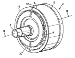
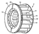
図1に、本発明のLRRCC2の、一部を露出させた斜視図が示してある。概ね円筒形状の圧縮機2は3つの主たる部品から成る。すなわちシャフト6に取り付けた内部の羽根車4と円筒体の湾曲表面として構成したケーシング8。シャフト6は静止し有利に中空にされ、これに、図3で詳しく見るように羽根車4を回転可能に連結する。図2に示す羽根車4は、コア14の周りに取り付けた複数の放射状に延びる羽根10と、同心の内方縁部16と外方縁部16'とを持つ環状の側壁12とから成る。図から分かるように、羽根10は以下に議論する理由により外方縁部16より短寸に終端させるのが得策である。さらに図1には、羽根車4に対して偏心的に回転可能に連結され、羽根10の外方縁部を跨いで両側壁12間に渡されるケーシング8が示してある。随意に、ケーシング8は機械的に羽根車4に連結される。この目的のため、これには内側の歯20を持つ側方リング18が取り付けてあり、内側の歯20が、側壁12の外側に取り付けるリング24に作られた外側の歯22と噛み合うようにされている。したがって、歯20と22とが噛み合うと、羽根車4はケーシング8の速度に対して一定の速度でシャフト6の周りを回転する。好ましくは、ケーシング8の速度は羽根車4の速度の70%より大きくすべきである。
FIG. 1 is a perspective view in which a part of the LRRCC 2 of the present invention is exposed. The generally cylindrical compressor 2 consists of three main parts. That is, a
羽根車4に対するケーシング8の偏心ecrは、式:
ecr<(1−c)/3
で与える。ここでecr=e/R。eは羽根車とケーシング軸との距離、cはシャフト6の半径Cとケーシング8の半径Rとの比である。
The eccentricity ecr of the
ecr <(1-c) / 3
Give in. Where ecr = e / R. e is the distance between the impeller and the casing shaft, and c is the ratio of the radius C of the shaft 6 to the radius R of the
図3、4も併せて参照すれば分かるように、シャフトに取り付けた羽根車とケーシングとを組み立てると、ケーシング8の内部には、ケーシング8の内方表面と羽根車4とで画成される2つの別領域、すなわち羽根10の縁部がケーシング8の内方表面に次第に接近して配され回転する圧縮領域Zcomと、羽根10の縁部がケーシング8の内方表面に沿って次第に離間した状態で配され回転する拡張領域Zexとが形成される。図3にはまた、羽根車4をシャフト6に連結する軸受26と、中空シャフトの入口部分6inと、仕切り28により入口部分6inから隔離される出口部分6outも示してある。
3 and 4, when the impeller attached to the shaft and the casing are assembled, the inside of the
本発明によれば、ケーシング8はモーター(図示せず)などの外部駆動手段により駆動され、駆動手段はベルト、ギア等の任意適当な手段でケーシングに連結される。図3に、軸受32を介してシャフト6に取り付けたケーシング/駆動装置連結手段30が示してある。駆動装置連結手段30はケーシング8のどちらかの側部、または(図示したように)両側部に設けることができる。または別法として、ケーシング8はその外側表面に設けた手段で駆動してもよい。突条34にはモーターにつながる案内駆動ベルト(図示せず)が設けられる。
According to the present invention, the
圧縮領域Zcomと拡張領域Zexとの境界近傍での半径方向の液体の流れは、羽根10とケーシング8との各区画間の液体速度の大きなばらつきと関連する。この接線速度のばらつきは散逸的である。散逸速度を減じるために、本発明では羽根10の端部を羽根車の側壁12に比して短くしてある。こうすることで、羽根10の端部とケーシング8との間の間隔が大きくなり、散逸速度は減じられて効率が増す。
Radial liquid flow in the vicinity of the boundary between the compression region Z com and the extended region Z ex is associated with large variations in the liquid velocity between each section of the
圧縮領域Zcomでシャフトの仕事は熱に変換される。本発明の別の特徴によれば、圧縮領域Zcomに低温の流体を導入でき、熱は圧縮領域から低温の液体により取り出される。こうして圧縮ガスは低温となり、高温のガスでなく低温のガスの圧縮にシャフトの仕事は少ししか要しないから、圧縮機の効率はさらに高まる。 The shaft work is converted into heat in the compression zone Zcom . According to another feature of the invention, a cold fluid can be introduced into the compression zone Zcom and heat is extracted from the compression zone by a cold liquid. Thus, the compressed gas becomes low temperature, and the efficiency of the compressor is further increased because only a little work of the shaft is required to compress the low temperature gas instead of the high temperature gas.
好ましい実施形態では、流体(通常低温の水)を噴霧化して直接圧縮領域Zcomに吹き付ける。効果的には、液滴容積の平均直径を200ミクロンより小径にするのが得策である。発生した熱の大部分を取り出し気温を低レベルで保つために、液体のマスフローml(kg/s)を空気のマスフローと比較できるように例えばml>ma/3にすべきである。 In a preferred embodiment, sprayed in direct compression region Z com by spraying the fluid (usually cold water). Effectively, it is advisable to make the average diameter of the droplet volume smaller than 200 microns. In order to extract most of the generated heat and keep the temperature low, the liquid mass flow ml (kg / s) should be, for example, ml> ma / 3 so that it can be compared with the air mass flow.
図4に、周りに羽根10を取り付けたコア14内に形成される吹付けノズル36が示してある。図から分かるように、吹付けノズル36は仕切り28上に形成され、噴霧化流体を2方向に仕向けることができる。
FIG. 4 shows a
2領域の境界または界面近傍の圧縮領域Zcomでは、液体の波が発生する。波は、本来散逸的な、拡張領域Zexへの圧縮空気の漏れと連動する。波の振幅に加えて漏れは、隣接する2つの羽根の間隔と共に大きくなる。この漏れを少なくするために、羽根の数は10より多数にすべきである。さらに、漏れた空気は拡張領域Zexに広がる要がある。このため、羽根10は中心シャフト6に接近させて、羽根とダクトとの間隔を小さくし、狭隘個所Tecと低圧の入口の開放部Teとの角度αは1/2ラジアンを超えるようにすべきである。
In the compression region Zcom near the boundary between the two regions or the interface, a liquid wave is generated. Waves, of inherently dissipative, in conjunction with the leakage of the compressed air to the expansion region Z ex. In addition to wave amplitude, leakage increases with the spacing between two adjacent vanes. To reduce this leakage, the number of blades should be greater than ten. Furthermore, the leaked air needs to spread to the expansion region Zex . For this reason, the
当業者には明らかなように、本発明は上述の説明的実施形態の細目に限定されず、また本発明は本発明の精神または本質的特性から逸脱することなくその他の具体的形態で具現化できる。したがって本発明の実施形態は全ての点で説明のためであって限定するものではない。本発明の範囲は上述の説明ではなく添付クレームにより示され、したがってクレーム等価物の意味と範囲とに入る全ての変更はクレームに包含されるものとする。 As will be apparent to those skilled in the art, the present invention is not limited to the details of the illustrative embodiments described above, and the invention may be embodied in other specific forms without departing from the spirit or essential characteristics of the invention. it can. Accordingly, the embodiments of the present invention are illustrative in all respects and not limiting. The scope of the invention is indicated by the appended claims rather than the foregoing description, and all changes that come within the meaning and scope of the claims equivalents are therefore intended to be embraced by the claims.
2 LRRCC
4 羽根車
6 シャフト
6in シャフト入口部分
6out シャフト出口部分
8 ケーシング
10 羽根
12 環状側壁
26、32 軸受
28 仕切り
30 駆動装置連結手段
34 突条
Zcom 圧縮領域
Zex 拡張領域
2 LRRCC
4 impeller 6 shaft 6 in- shaft inlet portion 6 out-
10
Claims (10)
前記シャフトに回転可能に連結された、コア及び複数の放射状に伸びる羽根とを有した羽根車と;
前記羽根車に対して内方表面と外方表面とを偏心的に回転可能に配置させた円筒形ケーシングであって、前記羽根車と共に、前記羽根の縁部がケーシングの内方表面に次第に接近して回転する圧縮領域と、前記羽根の縁部がケーシングの内方表面に沿って次第に離間した状態で回転する拡張領域とを画成する円筒形ケーシングと;
前記羽根に及び/または前記コアに側面で連結される円盤状部分と;
前記拡張領域と連通する入口ポートと;
前記圧縮領域と連通する出口ポートと;
前記ケーシングに回転運動を与える駆動装置と;を具備することを特徴とする液体リング回転ケーシング圧縮機(LRRCC)。 A shaft;
An impeller having a core and a plurality of radially extending blades rotatably coupled to the shaft;
A cylindrical casing in which an inner surface and an outer surface are arranged to be eccentrically rotatable with respect to the impeller, and together with the impeller, the edge of the blade gradually approaches the inner surface of the casing. A cylindrical casing defining a rotating compression area and an expansion area rotating with the blade edges gradually spaced along the inner surface of the casing;
A disc-like portion connected to the blades and / or to the core on the side;
An inlet port in communication with the expansion area;
An outlet port in communication with the compression region;
A liquid ring rotary casing compressor (LRRRCC), comprising: a drive device that imparts rotational motion to the casing.
Applications Claiming Priority (2)
| Application Number | Priority Date | Filing Date | Title |
|---|---|---|---|
| IL169162A IL169162A (en) | 2005-06-15 | 2005-06-15 | Liquid ring compressor |
| PCT/IL2006/000680 WO2006134590A1 (en) | 2005-06-15 | 2006-06-12 | Liquid ring compressor |
Publications (2)
| Publication Number | Publication Date |
|---|---|
| JP2008544141A true JP2008544141A (en) | 2008-12-04 |
| JP2008544141A5 JP2008544141A5 (en) | 2009-08-06 |
Family
ID=36933489
Family Applications (1)
| Application Number | Title | Priority Date | Filing Date |
|---|---|---|---|
| JP2008516499A Pending JP2008544141A (en) | 2005-06-15 | 2006-06-12 | Liquid ring compressor |
Country Status (6)
| Country | Link |
|---|---|
| US (2) | US9181948B2 (en) |
| EP (1) | EP1896726A1 (en) |
| JP (1) | JP2008544141A (en) |
| CN (1) | CN101198792B (en) |
| IL (1) | IL169162A (en) |
| WO (1) | WO2006134590A1 (en) |
Cited By (2)
| Publication number | Priority date | Publication date | Assignee | Title |
|---|---|---|---|---|
| JP2011511208A (en) * | 2008-02-07 | 2011-04-07 | レスキネン,ペカ | Device for evenly distributing flow between two or more objects |
| JP2012087783A (en) * | 2010-10-11 | 2012-05-10 | General Electric Co <Ge> | Liquid ring compressor for subsea compression of wet gas |
Families Citing this family (10)
| Publication number | Priority date | Publication date | Assignee | Title |
|---|---|---|---|---|
| IL169162A (en) | 2005-06-15 | 2013-04-30 | Agam Energy Systems Ltd | Liquid ring compressor |
| IL204389A (en) | 2010-03-09 | 2013-07-31 | Agam Energy Systems Ltd | Liquid ring rotating casing steam turbine and method of use thereof |
| WO2012071538A2 (en) * | 2010-11-23 | 2012-05-31 | The Ohio State University | Liquid ring heat engine |
| EP2783115B1 (en) * | 2011-11-24 | 2018-06-27 | Sterling Industry Consult GmbH | Liquid ring vacuum pump |
| TWI471487B (en) * | 2012-09-14 | 2015-02-01 | Tekomp Technology Co Ltd | Screw Rotor Type Liquid Ring Compressor |
| US8695335B1 (en) * | 2012-11-23 | 2014-04-15 | Sten Kreuger | Liquid ring system and applications thereof |
| TWM483123U (en) * | 2014-03-11 | 2014-08-01 | Trusval Technology Co Ltd | Generation device for gas dissolution into liquid and fluid nozzle |
| US10837443B2 (en) * | 2014-12-12 | 2020-11-17 | Nuovo Pignone Tecnologic - SRL | Liquid ring fluid flow machine |
| RU2614112C1 (en) * | 2016-03-09 | 2017-03-22 | Федеральное государственное бюджетное образовательное учреждение высшего образования "Тамбовский государственный технический университет" (ФГБОУ ВО ТГТУ) | Liquid ring machine with thermal accumulator |
| GB2610324B (en) * | 2022-10-24 | 2023-08-30 | Paul Kelsall Richard | A liquid ring rotor |
Citations (5)
| Publication number | Priority date | Publication date | Assignee | Title |
|---|---|---|---|---|
| US953222A (en) * | 1904-04-13 | 1910-03-29 | Nash Engineering Co | Displacement structure. |
| US2201575A (en) * | 1938-03-04 | 1940-05-21 | Ernest R Corneil | Machine for transferring fluids |
| US4112688A (en) * | 1976-10-08 | 1978-09-12 | Shaw John B | Positive displacement gas expansion engine with low temperature differential |
| JPH03505901A (en) * | 1988-06-08 | 1991-12-19 | ペンタモ オイ | liquid ring compressor |
| JPH10512643A (en) * | 1995-01-17 | 1998-12-02 | エナジー コンバーターズ エルティーデー | Liquid annular compressor and turbine and air conditioning system using them |
Family Cites Families (13)
| Publication number | Priority date | Publication date | Assignee | Title |
|---|---|---|---|---|
| US1463646A (en) * | 1923-03-06 | 1923-07-31 | Chilowsky Constantin | Apparatus for performing cycles of compression, expansion, combustion, suction, exhaust, and the like |
| FR865434A (en) | 1940-05-04 | 1941-05-23 | Crompressor and rotary motor | |
| FR999464A (en) * | 1949-10-26 | 1952-01-31 | Ile D Etudes Et De Rech S Meca | Improvements to liquid ring type pumps |
| US2937499A (en) * | 1956-03-09 | 1960-05-24 | Inst Schienenfahrzeuge | Liquid ring gaseous fluid displacing device |
| US4122688A (en) * | 1976-07-30 | 1978-10-31 | Hitachi, Ltd. | Refrigerating system |
| US4747752A (en) * | 1987-04-20 | 1988-05-31 | Somarakis, Inc. | Sealing and dynamic operation of a liquid ring pump |
| DE3718551A1 (en) | 1987-06-03 | 1988-12-15 | Wilhelm Dipl Ing Hettenhausen | Liquid-ring expansion engine with condensate return |
| US4981413A (en) * | 1989-04-27 | 1991-01-01 | Ahlstrom Corporation | Pump for and method of separating gas from a fluid to be pumped |
| US5100300A (en) * | 1990-12-28 | 1992-03-31 | The Nash Engineering Company | Liquid ring pumps having rotating lobe liners with end walls |
| US5722255A (en) * | 1996-12-04 | 1998-03-03 | Brasz; Joost J. | Liquid ring flash expander |
| US6412291B1 (en) * | 2000-09-05 | 2002-07-02 | Donald C. Erickson | Air compression improvement |
| IL169162A (en) | 2005-06-15 | 2013-04-30 | Agam Energy Systems Ltd | Liquid ring compressor |
| DE102006049944A1 (en) | 2006-08-29 | 2008-03-06 | Gerhold, Richard, Dr. | Heat engine has three liquid ring compressors and has throttle between compressors with which compressed air is released into compressor, cooled and determined by expansion, releases fluid as condensate behind throttle |
-
2005
- 2005-06-15 IL IL169162A patent/IL169162A/en not_active IP Right Cessation
-
2006
- 2006-06-12 CN CN2006800212653A patent/CN101198792B/en active Active
- 2006-06-12 EP EP06745142A patent/EP1896726A1/en not_active Withdrawn
- 2006-06-12 JP JP2008516499A patent/JP2008544141A/en active Pending
- 2006-06-12 US US11/917,153 patent/US9181948B2/en active Active
- 2006-06-12 WO PCT/IL2006/000680 patent/WO2006134590A1/en not_active Application Discontinuation
-
2014
- 2014-09-22 US US14/492,325 patent/US9556871B2/en not_active Expired - Fee Related
Patent Citations (5)
| Publication number | Priority date | Publication date | Assignee | Title |
|---|---|---|---|---|
| US953222A (en) * | 1904-04-13 | 1910-03-29 | Nash Engineering Co | Displacement structure. |
| US2201575A (en) * | 1938-03-04 | 1940-05-21 | Ernest R Corneil | Machine for transferring fluids |
| US4112688A (en) * | 1976-10-08 | 1978-09-12 | Shaw John B | Positive displacement gas expansion engine with low temperature differential |
| JPH03505901A (en) * | 1988-06-08 | 1991-12-19 | ペンタモ オイ | liquid ring compressor |
| JPH10512643A (en) * | 1995-01-17 | 1998-12-02 | エナジー コンバーターズ エルティーデー | Liquid annular compressor and turbine and air conditioning system using them |
Cited By (2)
| Publication number | Priority date | Publication date | Assignee | Title |
|---|---|---|---|---|
| JP2011511208A (en) * | 2008-02-07 | 2011-04-07 | レスキネン,ペカ | Device for evenly distributing flow between two or more objects |
| JP2012087783A (en) * | 2010-10-11 | 2012-05-10 | General Electric Co <Ge> | Liquid ring compressor for subsea compression of wet gas |
Also Published As
| Publication number | Publication date |
|---|---|
| EP1896726A1 (en) | 2008-03-12 |
| US20150017027A1 (en) | 2015-01-15 |
| US9556871B2 (en) | 2017-01-31 |
| IL169162A (en) | 2013-04-30 |
| CN101198792B (en) | 2012-05-16 |
| US20090290993A1 (en) | 2009-11-26 |
| WO2006134590A1 (en) | 2006-12-21 |
| CN101198792A (en) | 2008-06-11 |
| US9181948B2 (en) | 2015-11-10 |
Similar Documents
| Publication | Publication Date | Title |
|---|---|---|
| JP2008544141A (en) | Liquid ring compressor | |
| JP4695097B2 (en) | Centrifugal fan, pump or turbine housing | |
| JP2008544141A5 (en) | ||
| CN102356214B (en) | Reaction turbine | |
| US20020157636A1 (en) | Two-dimensional positive rotary displacement engine | |
| US6976486B2 (en) | Apparatus and method for heating fluids | |
| US5704774A (en) | Pump with twin cylindrical impellers | |
| KR102540138B1 (en) | Dual impeller | |
| JP2016522357A (en) | Centrifugal rotor | |
| EA012818B1 (en) | Rotor for rotary machine and a rotary machine | |
| JP2000310197A (en) | Centrifugal blast impeller | |
| US4422832A (en) | Liquid ring pump with vanes in liquid ring | |
| JP2005537420A (en) | Centrifugal impeller and pump device | |
| JPH09100797A (en) | Impeller of centrifugal compressor | |
| US4531887A (en) | Continuous blade multi-stage pump | |
| JPH02149276A (en) | Precession type centrifugal pump | |
| RU2132973C1 (en) | Centrifugal reaction impeller | |
| JPH11294392A (en) | Centrifugal compressor | |
| JP2002227795A (en) | Centrifugal pump | |
| JP2660793B2 (en) | Blood circulation assist pump installed in the body | |
| RU10803U1 (en) | JET PUMP COMPRESSOR UNIT | |
| JP3794543B2 (en) | Centrifugal compressor | |
| SU1751416A1 (en) | Axial-flow pump | |
| KR100300344B1 (en) | Pump | |
| JP2003343484A (en) | Centrifugal blower and power working machine |
Legal Events
| Date | Code | Title | Description |
|---|---|---|---|
| A521 | Written amendment |
Free format text: JAPANESE INTERMEDIATE CODE: A523 Effective date: 20090612 |
|
| A621 | Written request for application examination |
Free format text: JAPANESE INTERMEDIATE CODE: A621 Effective date: 20090612 |
|
| A977 | Report on retrieval |
Free format text: JAPANESE INTERMEDIATE CODE: A971007 Effective date: 20111019 |
|
| A131 | Notification of reasons for refusal |
Free format text: JAPANESE INTERMEDIATE CODE: A131 Effective date: 20111026 |
|
| A601 | Written request for extension of time |
Free format text: JAPANESE INTERMEDIATE CODE: A601 Effective date: 20120126 |
|
| A602 | Written permission of extension of time |
Free format text: JAPANESE INTERMEDIATE CODE: A602 Effective date: 20120202 |
|
| A521 | Written amendment |
Free format text: JAPANESE INTERMEDIATE CODE: A523 Effective date: 20120426 |
|
| A02 | Decision of refusal |
Free format text: JAPANESE INTERMEDIATE CODE: A02 Effective date: 20121025 |
|
| A521 | Written amendment |
Free format text: JAPANESE INTERMEDIATE CODE: A821 Effective date: 20130226 |