JP2008542829A - Microlithography projection objective - Google Patents
Microlithography projection objective Download PDFInfo
- Publication number
- JP2008542829A JP2008542829A JP2008513975A JP2008513975A JP2008542829A JP 2008542829 A JP2008542829 A JP 2008542829A JP 2008513975 A JP2008513975 A JP 2008513975A JP 2008513975 A JP2008513975 A JP 2008513975A JP 2008542829 A JP2008542829 A JP 2008542829A
- Authority
- JP
- Japan
- Prior art keywords
- projection objective
- shield
- objective lens
- light
- projection
- Prior art date
- Legal status (The legal status is an assumption and is not a legal conclusion. Google has not performed a legal analysis and makes no representation as to the accuracy of the status listed.)
- Pending
Links
Images


Classifications
-
- G—PHYSICS
- G03—PHOTOGRAPHY; CINEMATOGRAPHY; ANALOGOUS TECHNIQUES USING WAVES OTHER THAN OPTICAL WAVES; ELECTROGRAPHY; HOLOGRAPHY
- G03F—PHOTOMECHANICAL PRODUCTION OF TEXTURED OR PATTERNED SURFACES, e.g. FOR PRINTING, FOR PROCESSING OF SEMICONDUCTOR DEVICES; MATERIALS THEREFOR; ORIGINALS THEREFOR; APPARATUS SPECIALLY ADAPTED THEREFOR
- G03F7/00—Photomechanical, e.g. photolithographic, production of textured or patterned surfaces, e.g. printing surfaces; Materials therefor, e.g. comprising photoresists; Apparatus specially adapted therefor
- G03F7/70—Microphotolithographic exposure; Apparatus therefor
- G03F7/70216—Mask projection systems
- G03F7/70225—Optical aspects of catadioptric systems, i.e. comprising reflective and refractive elements
-
- G—PHYSICS
- G02—OPTICS
- G02B—OPTICAL ELEMENTS, SYSTEMS OR APPARATUS
- G02B17/00—Systems with reflecting surfaces, with or without refracting elements
- G02B17/08—Catadioptric systems
-
- G—PHYSICS
- G03—PHOTOGRAPHY; CINEMATOGRAPHY; ANALOGOUS TECHNIQUES USING WAVES OTHER THAN OPTICAL WAVES; ELECTROGRAPHY; HOLOGRAPHY
- G03F—PHOTOMECHANICAL PRODUCTION OF TEXTURED OR PATTERNED SURFACES, e.g. FOR PRINTING, FOR PROCESSING OF SEMICONDUCTOR DEVICES; MATERIALS THEREFOR; ORIGINALS THEREFOR; APPARATUS SPECIALLY ADAPTED THEREFOR
- G03F7/00—Photomechanical, e.g. photolithographic, production of textured or patterned surfaces, e.g. printing surfaces; Materials therefor, e.g. comprising photoresists; Apparatus specially adapted therefor
- G03F7/70—Microphotolithographic exposure; Apparatus therefor
- G03F7/70058—Mask illumination systems
- G03F7/702—Reflective illumination, i.e. reflective optical elements other than folding mirrors, e.g. extreme ultraviolet [EUV] illumination systems
-
- G—PHYSICS
- G03—PHOTOGRAPHY; CINEMATOGRAPHY; ANALOGOUS TECHNIQUES USING WAVES OTHER THAN OPTICAL WAVES; ELECTROGRAPHY; HOLOGRAPHY
- G03F—PHOTOMECHANICAL PRODUCTION OF TEXTURED OR PATTERNED SURFACES, e.g. FOR PRINTING, FOR PROCESSING OF SEMICONDUCTOR DEVICES; MATERIALS THEREFOR; ORIGINALS THEREFOR; APPARATUS SPECIALLY ADAPTED THEREFOR
- G03F7/00—Photomechanical, e.g. photolithographic, production of textured or patterned surfaces, e.g. printing surfaces; Materials therefor, e.g. comprising photoresists; Apparatus specially adapted therefor
- G03F7/70—Microphotolithographic exposure; Apparatus therefor
- G03F7/70216—Mask projection systems
- G03F7/70283—Mask effects on the imaging process
-
- G—PHYSICS
- G03—PHOTOGRAPHY; CINEMATOGRAPHY; ANALOGOUS TECHNIQUES USING WAVES OTHER THAN OPTICAL WAVES; ELECTROGRAPHY; HOLOGRAPHY
- G03F—PHOTOMECHANICAL PRODUCTION OF TEXTURED OR PATTERNED SURFACES, e.g. FOR PRINTING, FOR PROCESSING OF SEMICONDUCTOR DEVICES; MATERIALS THEREFOR; ORIGINALS THEREFOR; APPARATUS SPECIALLY ADAPTED THEREFOR
- G03F7/00—Photomechanical, e.g. photolithographic, production of textured or patterned surfaces, e.g. printing surfaces; Materials therefor, e.g. comprising photoresists; Apparatus specially adapted therefor
- G03F7/70—Microphotolithographic exposure; Apparatus therefor
- G03F7/708—Construction of apparatus, e.g. environment aspects, hygiene aspects or materials
- G03F7/70908—Hygiene, e.g. preventing apparatus pollution, mitigating effect of pollution or removing pollutants from apparatus
- G03F7/70941—Stray fields and charges, e.g. stray light, scattered light, flare, transmission loss
Abstract
【課題】物体平面に配置されるパターンを像平面内に結像するマイクロリソグラフィ投影対物レンズにおいて迷光を抑制する。
【解決手段】物体平面に配置されるパターンを像平面内に結像するマイクロリソグラフィ投影対物レンズ10が提供され、第1対物レンズ部16と、第2対物レンズ部18と、少なくとも一つの第3対物レンズ部20とを備え、第2対物レンズ部18は、第1対物レンズ部10における光伝搬方向および第3対物レンズ部20における光伝搬方向と異なる光伝搬方向を規定し、かつ第1対物レンズ部10と第2対物レンズ部18との間および第2対物レンズ部18と第3対物レンズ部20との間に少なくとも一つのビーム偏向装置22をさらに備え、少なくとも一つのシールド24が、第1対物レンズ部16から第3対物レンズ部内20への直接光漏れが少なくとも減少するようにしてビーム偏向装置22の領域に配置される。
【選択図】図1Stray light is suppressed in a microlithographic projection objective lens that forms an image on a pattern arranged in an object plane in an image plane.
A microlithographic projection objective lens 10 for imaging a pattern arranged in an object plane in an image plane is provided, and includes a first objective lens section 16, a second objective lens section 18, and at least one third. The second objective lens unit 18 defines a light propagation direction different from the light propagation direction in the first objective lens unit 10 and the light propagation direction in the third objective lens unit 20, and the first objective lens unit 20. At least one beam deflecting device 22 is further provided between the lens unit 10 and the second objective lens unit 18 and between the second objective lens unit 18 and the third objective lens unit 20, and at least one shield 24 includes the first shield 24. Direct light leakage from the first objective lens unit 16 to the third objective lens unit 20 is arranged in the region of the beam deflecting device 22 so as to reduce at least.
[Selection] Figure 1
Description
本発明は、物体平面に配置されるパターンを像平面に結像するマイクロリソグラフィ投影対物レンズに関する。
本発明は、さらに、そのような投影対物レンズを有する投影露光機に関する。
本発明は、さらに、半導体部品および他の微細構造サブアセンブリを製造する方法に関する。
The present invention relates to a microlithographic projection objective that images a pattern placed in an object plane onto an image plane.
The invention further relates to a projection exposure machine having such a projection objective.
The invention further relates to a method of manufacturing semiconductor components and other microstructure subassemblies.
マイクロリソグラフィ投影対物レンズは、半導体部品および他の微細構造部品を製造する投影露光機であり、特にウエハスキャナーおよびウエハステッパーにおいて用いられる。そのような投影露光機は、一般にマスクまたはレティクルとしても呼ばれるフォトマスクまたは焦点板からのパターンを、感光層で被覆された対象物(基板)上に非常に高い解像度で投影する目的を果たす。この場合、マスクは物体平面に配置され、かつ基板は投影対物レンズの像平面に配置される。 Microlithographic projection objectives are projection exposure machines that produce semiconductor components and other microstructured components, and are used in particular in wafer scanners and wafer steppers. Such a projection exposure machine serves the purpose of projecting a pattern from a photomask or focusing plate, also referred to as a mask or reticle, onto an object (substrate) coated with a photosensitive layer with very high resolution. In this case, the mask is placed in the object plane and the substrate is placed in the image plane of the projection objective.
投影対物レンズの中で公知であるのは、光学素子を屈折することおよび反射することの組み合わせ、たとえば特にレンズと鏡との組み合わせとなるものである。そのような投影対物レンズは、カタディオプトリック(反射屈折)と呼ばれる。
カタディオプトリック投影対物レンズの例は、下記特許文献1に開示されている。カタディオプトリック投影対物レンズのさらなる例は、下記特許文献2から理解される。
Known among projection objectives are combinations of refracting and reflecting optical elements, such as in particular a combination of a lens and a mirror. Such a projection objective is called catadioptric (catadioptric).
An example of a catadioptric projection objective is disclosed in Patent Document 1 below. Further examples of catadioptric projection objectives can be understood from US Pat.
たとえば、下記特許文献1に開示されているカタディオプトリック投影対物レンズは、物体平面から、第1対物レンズ部ならびそれに隣接する第2対物レンズ部、およびそれに隣接する第3対物レンズ部を有している。ビーム偏向は、第1対物レンズ部から第2対物レンズ部までの移行部において、第1折畳み鏡によって形成されるビーム偏向装置によって生じる。第2対物レンズ部は、ビーム偏向装置に再び光を逆反射する凹面鏡を有し、かつ第2対物レンズ部から第3対物レンズ部までの移行部においてさらなる折畳み鏡を有するビーム偏向装置は、次に光を第3対物レンズ部内に方向づける。2つの折畳み鏡は、互いにほぼ90度の角度である。しかも、この公知の投影対物レンズの場合には、光学配置は、中間像が第3対物レンズ部において生成されるように行われている。 For example, a catadioptric projection objective disclosed in the following Patent Document 1 includes a first objective lens part, a second objective lens part adjacent to the first objective lens part, and a third objective lens part adjacent to the first objective lens part from the object plane. ing. Beam deflection is caused by the beam deflection device formed by the first folding mirror at the transition from the first objective lens part to the second objective lens part. The second objective lens unit has a concave mirror for retroreflecting light again on the beam deflecting device, and a beam deflecting device having a further folding mirror at the transition from the second objective lens unit to the third objective lens unit is To direct light into the third objective lens section. The two folding mirrors are approximately 90 degrees to each other. Moreover, in the case of this known projection objective, the optical arrangement is such that an intermediate image is generated in the third objective part.
本発明の意味において、ビーム偏向装置は、折畳み鏡によって形成されることが可能であるだけでなく、装置を偏向させる装置は、たとえば、ビーム偏向に好適なビームスプリッタキューブまたは他の光学素子を有することができる。
ビーム偏向を有する投影対物レンズの場合に生じることがある問題は、投影対物レンズを通過する光の一部分が、ビーム偏向装置において、第2対物レンズ部を抜かして第1投影対物レンズ部から第3対物レンズ部内に直接漏れることである。したがって、規定順序ですべての光学素子を横断する光のみが適切な結像に貢献することができるように投影対物レンズが設計されているので、そのような迷光または偽光は投影対物レンズのすべての光学素子を横断せず、ひいては投影対物レンズの像平面内に、投影対物レンズの物体平面に配置されるパターンを正しく結像することができない。
In the sense of the present invention, the beam deflection device can be formed not only by a folding mirror, but also the device for deflecting the device has, for example, a beam splitter cube or other optical element suitable for beam deflection. be able to.
A problem that may occur in the case of a projection objective lens having beam deflection is that a part of the light passing through the projection objective lens is removed from the first projection objective lens portion by removing the second objective lens portion in the beam deflection apparatus. Leak directly into the objective lens. Therefore, since stray light or spurious light is all of the projection objective because the projection objective is designed so that only light that traverses all optical elements in a defined order can contribute to proper imaging. The pattern arranged on the object plane of the projection objective lens cannot be correctly formed in the image plane of the projection objective lens.
上記特許文献1は、迷光または偽光を減少させるために、中間像の領域に迷光絞りを配置することを提案している。しかしながら、このことは、第1対物レンズ部から第3対物レンズ部内への部分的な直接光漏れの問題を効果的に軽減するものではなく、まして解決もしない。
すでに上述したように、マイクロリソグラフィ投影露光機は、ステッパーとしてまたはスキャナーとして設計されている。ステッパーの場合には、正方形視野または長方形視野が静止ウエハ上に露光される。円形視野は、完全なウエハ表面を活用することができないという作用を有するものであり、よって半導体の大量生産用施設では用いられない。
The above-mentioned Patent Document 1 proposes arranging a stray light stop in the region of the intermediate image in order to reduce stray light or false light. However, this does not effectively reduce or even solve the problem of partial direct light leakage from the first objective lens section into the third objective lens section.
As already mentioned above, microlithographic projection exposure machines are designed as steppers or as scanners. In the case of a stepper, a square field or a rectangular field is exposed on a stationary wafer. The circular field of view has the effect that a complete wafer surface cannot be utilized, and is therefore not used in a facility for mass production of semiconductors.
スキャナーの場合には、パターン(レティクル)およびウエハが移動し、ウエハおよびレティクル上に露光される視野は、正方形または長方形である。スキャナーは、好ましくは、半導体の大量生産において用いられている。
長方形視野形状は、後の工程段階、特にウエハを個別片に分割する工程から好ましいが、生産技術の理由で、ステッパーおよびスキャナーで用いるための投影対物レンズは、一般に円形レンズ素子から構成されている。
In the case of a scanner, the pattern (reticle) and wafer move and the field of view exposed on the wafer and reticle is square or rectangular. Scanners are preferably used in the mass production of semiconductors.
A rectangular field shape is preferred from later process steps, particularly the process of dividing the wafer into individual pieces, but for production engineering reasons, projection objectives for use in steppers and scanners are generally composed of circular lens elements. .
長方形視野露光の場合もまた、投影されたパターンの結像に貢献しない偽光が生じる。ビーム偏向を有する投影対物レンズの場合の上述の作用に加えて、偽光が、特定の対物レンズ部を抜かして一つの対物レンズ部から他の対物レンズ部内に漏れる場合が、偽光は、一般に個々のレンズ表面およびウエハのパターン(レティクル)の表面での反射からも生じることがあり、レンズ表面上の反射防止層の使用にもかかわらず、そのような反射はなくならない。 In the case of rectangular field exposure, spurious light is generated that does not contribute to the imaging of the projected pattern. In addition to the above-described effects in the case of a projection objective lens having beam deflection, false light generally leaks from one objective lens part into another objective lens part when a specific objective lens part is pulled out. It can also result from reflections on the surface of individual lens surfaces and wafer patterns (reticles), and such reflections do not go away despite the use of an anti-reflective layer on the lens surface.
特定の原因にかかわらず、偽光は、露光工程によって結像される構造が偽光の背景のせいで広がるので、ウエハ上に落ちるとすぐ、リソグラフィ工程を妨げる。言い換えると、投影対物レンズにおいて伝搬しておりかつ投影対物レンズの像平面に達する偽光は、パターンの像平面内への結像のコントラストを妨げる。
すでに上述したように、投影対物レンズは、結像のために用いることができる結像ビーム経路が規定順序ですべての光学作用表面を横断する場合のみ、機能の点で適切に動作する。投影対象物のすべての光学作用表面を横断しない、または投影対物レンズのすべての光学活性表面を実際に横断する間に適切な結像に必要とされる以外の順序で横断する偽光によって、偽像が投影対物レンズにおいて生じている。偽光がウエハに達するために、偶数回のさらなる反射が起きなければならない。さらなる反射は、屈折するように設計されているレンズ表面での反射から始まる。今後、光は他のレンズ表面で、またはカタディオプトリック投影対物レンズの場合には鏡で逆反射することができる。
Regardless of the specific cause, the false light interferes with the lithography process as soon as it falls on the wafer because the structure imaged by the exposure process spreads because of the background of the false light. In other words, spurious light propagating in the projection objective and reaching the image plane of the projection objective impedes the contrast of the imaging into the image plane of the pattern.
As already mentioned above, the projection objective works properly in terms of function only if the imaging beam path that can be used for imaging traverses all optical working surfaces in a defined order. False light that does not traverse all optical working surfaces of the projection object or traverses in an order other than that required for proper imaging while actually traversing all optically active surfaces of the projection objective An image is generated at the projection objective. In order for the false light to reach the wafer, an even number of further reflections must occur. Further reflection begins with reflection at the lens surface that is designed to refract. From now on, the light can be retro-reflected on other lens surfaces or in the case of catadioptric projection objectives with a mirror.
この新規ビーム経路に属する光学システムは、「拡大」光学システムとして呼ばれる。そのような「拡大」システムは、実際の投影対物レンズのように結像する。この結像に貢献する偽光は、多くは反射を減少させるための層も有する屈折表面での反射から主として生じるので、確かに弱いものである。
投影対物レンズの「拡大」光学システムは、偽像が投影対物レンズの像平面の近傍に生成されるように、偽光をウエハの方向に誘導する。
The optical system belonging to this new beam path is referred to as an “expanding” optical system. Such “magnification” systems image like a real projection objective. The spurious light that contributes to this imaging is certainly weak because it mostly arises from reflection at the refractive surface that also has a layer to reduce reflection.
The “magnifying” optical system of the projection objective directs the false light in the direction of the wafer so that a false image is generated in the vicinity of the image plane of the projection objective.
いずれにしても、偽光ができるだけ効果的に抑制される投影対物レンズが必要であるように、投影対物レンズにおける偽光は投影対物レンズの結像特性を悪化させる。
マイクロリソグラフィ投影対物レンズにおけるさらに他の問題は、使用視野全体にわたって均一な開口を設けるという要求に関連して生じるものである。マイクロリソグラフィ用の投影対物レンズでは、たとえば、フォトリソグラフィ用対物レンズにおいて公知であるような口径食は望ましくない。先行技術から公知である投影対物レンズでは、投影対物レンズの瞳孔平面において一つの開口絞りのみを提供するのが一般的である。しかしながら、一つの開口絞りのみでは、使用視野にわたって所望の均一開口を保証することができないという光学設計が存在する。
In any case, the false light in the projection objective deteriorates the imaging characteristics of the projection objective so that a projection objective is required in which the false light is suppressed as effectively as possible.
Yet another problem with microlithographic projection objectives arises in connection with the requirement to provide a uniform aperture over the entire field of use. In projection objectives for microlithography, for example, vignetting as is known in photolithography objectives is undesirable. In projection objectives known from the prior art, it is common to provide only one aperture stop in the pupil plane of the projection objective. However, there is an optical design in which only a single aperture stop cannot guarantee a desired uniform aperture over the field of use.
視野にわたる不均一開口の理由は、いくつかの光線は、投影対物レンズの設計開口より大きい開口を有する物体平面から始まり、かつそのとき非常に強い収差があるので、それらの実際の瞳孔平面が、設計開口に等しいまたはそれより小さい開口を有する光線に属する瞳孔平面から間隔が開けられているものもあるということである。よって、これらのいわゆるオーバ開口光線は、システム開口絞りによって必ずしもつぶされるものではないが、光学部品が光伝搬を横切る方向に十分延びる場合は像平面に達することができる。これらのオーバ開口光線は、典型的には強い収差があり、かつ像平面に達するとき像視野の均一性を妨げる。 The reason for the non-uniform aperture across the field is that some rays start from an object plane with an aperture larger than the design aperture of the projection objective, and then have very strong aberrations, so their actual pupil plane is This means that some are spaced from the pupil plane belonging to a ray having an aperture equal to or smaller than the design aperture. Thus, these so-called over-aperture rays are not necessarily crushed by the system aperture stop, but can reach the image plane if the optical component extends sufficiently in the direction across light propagation. These over-aperture rays typically have strong aberrations and hinder image field uniformity when reaching the image plane.
前述した問題に加え、またそれとは無関係に、像平面が完全に露光されないままであるように投影対物レンズのビーム経路における光をマスクすることが、マイクロリソグラフィ投影対物レンズにおける目的となる。そのようにする動機は、レンズ加熱修正のための情報を得るために、回折強度分布を測定することであってもよい。さらに、露光工程の中断中、所望であれば、たとえば、できるだけ均一でかつ回転対称である投影対物レンズを加熱するために、投影対物レンズに、結像に用いられる光と相補的である照明を供給することが考えられる。この場合もまた、光が像平面に入らないことを確認しなければならない。
本発明の目的は、その結像特性が、迷光または偽光のより効果的な抑制によって改良される、最初に述べた種類のマクロリソグラフィ投影対物レンズを提供することである。
本発明のさらなる目的は、そのような投影対物レンズを有する投影露光機、およびそのような投影対物レンズを用いて半導体部品を製造する方法を提供することである。
The object of the present invention is to provide a macrolithographic projection objective of the kind mentioned at the outset, whose imaging properties are improved by more effective suppression of stray light or spurious light.
A further object of the present invention is to provide a projection exposure machine having such a projection objective and a method for manufacturing semiconductor components using such a projection objective.
本発明の第1態様によれば、物体平面に配置されるパターンを像平面内に結像するマイクロリソグラフィ投影対物レンズが提供され、第1対物レンズ部と、第2対物レンズ部と、少なくとも一つの第3対物レンズ部とを備え、第2対物レンズ部は、第1対物レンズ部における光伝搬方向および第3対物レンズ部における光伝搬方向と異なる光伝搬方向を規定し、かつ第1対物レンズ部と第2対物レンズ部との間および第2対物レンズ部と第3対物レンズ部との間に少なくとも一つのビーム偏向装置をさらに備え、少なくとも一つのシールドは、第1対物レンズ部から第3対物レンズ部内への直接光漏れが少なくとも減少するようにしてビーム偏向装置の領域に配置される。 According to the first aspect of the present invention, there is provided a microlithographic projection objective lens that forms an image in the image plane of a pattern arranged on an object plane, and includes at least one of a first objective lens portion, a second objective lens portion, and the like. And a third objective lens unit, the second objective lens unit defining a light propagation direction in the first objective lens unit and a light propagation direction different from the light propagation direction in the third objective lens unit, and the first objective lens And at least one beam deflecting device between the second objective lens unit and the second objective lens unit, and between the second objective lens unit and the third objective lens unit, wherein at least one shield is third from the first objective lens unit. It is arranged in the region of the beam deflection device in such a way that at least the direct light leakage into the objective lens part is reduced.
第2対物レンズ部を抜かしつつ第1対物レンズ部から第3対物レンズ部内への直接光漏れを、ビーム偏向装置の領域にシールドを設けることによって回避することができる。ビーム偏向装置を通り過ぎて第1対物レンズ部から第3対物レンズ部内へ直接漏れ、かつパターンの像平面内への結像を歪める一因となる可能性のある反射は、シールドによって無害となる。像平面の迷光または偽光の部分は、ビーム偏向装置の領域に少なくとも一つのシールドを設けることによって少なくとも減少する。 Direct light leakage from the first objective lens portion into the third objective lens portion while removing the second objective lens portion can be avoided by providing a shield in the region of the beam deflecting device. Reflections that pass directly through the beam deflector and leak directly from the first objective into the third objective and can distort the imaging of the pattern into the image plane are rendered harmless by the shield. The stray or false light portion of the image plane is at least reduced by providing at least one shield in the region of the beam deflector.
シールドは、好ましくは、結像ビーム経路を制限しないように配置および/または設計されるべきである。
本発明による投影対物レンズの場合に設けられるようなシールドは、システム開口絞りまたはそのような投影対物レンズに通常設けられる開口絞りと区別される。システム開口絞りは結像ビーム経路を制限し、一方シールドは、開口としてまたは開口がないシールド板として設計されるなら、結像に用いられる光の部分をできる限り制限または減少させてはならない。
The shield should preferably be arranged and / or designed so as not to limit the imaging beam path.
A shield as provided in the case of a projection objective according to the invention is distinguished from a system aperture stop or an aperture stop normally provided in such a projection objective. The system aperture stop limits the imaging beam path, while the shield should not limit or reduce as much as possible the portion of light used for imaging if designed as an aperture or as a shield plate without an aperture.
公知の投影対物レンズの場合のように、ビーム偏向装置が互いに対してある角度で配置される第1反射面および第2反射面を有するなら、少なくとも一つのシールドは、ビーム偏向装置の角頂点から第2対物レンズ部の方向に、すなわち部分的に該第2対物レンズ部内へ延びている。
この場合、シールドは、好ましくは板であり、好ましくは吸収性物質から、たとえば吸収性金属から作られる。あるいは、板上の吸収層によって吸収を達成することもできる。理想的には、吸収特性は用いる光の波長となる。
If the beam deflecting device has a first reflecting surface and a second reflecting surface arranged at an angle with respect to each other, as in the case of known projection objectives, at least one shield is from the corner vertex of the beam deflecting device. It extends in the direction of the second objective lens part, i.e. partially into the second objective lens part.
In this case, the shield is preferably a plate, preferably made from an absorbent material, for example from an absorbent metal. Alternatively, absorption can be achieved by an absorbent layer on the plate. Ideally, the absorption characteristic is the wavelength of light used.
シールドに加えて、ビーム偏向装置の領域では、投影対物レンズが第2および/または第3対物レンズ部に少なくとも一つの中間像を生成するときはいつでも、少なくとも一つのさらなる迷光シールドを中間像の領域に配置するのがさらに好ましい。
このようにして、像平面に入りかつ像平面においてパターンの像を悪化させる迷光および偽光の部分をさらに減少させることが可能である。
In addition to the shield, in the region of the beam deflection device, whenever the projection objective produces at least one intermediate image in the second and / or third objective part, at least one further stray light shield is provided in the intermediate image region. It is more preferable to arrange in the above.
In this way, it is possible to further reduce the stray light and false light portions that enter the image plane and deteriorate the image of the pattern in the image plane.
中間像の領域に配置されるシールドは、好ましくは結像ビーム経路を制限しない迷光絞りである。
さらに、少なくとも一つの迷光シールドをその活性断面に対して位置調整することができおよび/または可変であるのが好ましい。
この場合、迷光の減少を、少なくとも一つの迷光シールドの活性断面の位置調整および/または設定によって、たとえば板状のシールドを拡大または縮小することによって、それぞれの投影対物レンズについて最適化することができ、少なくとも一つの迷光シールドの活性断面の位置調整または設定によって結像ビーム経路が少なくとも実質的に制限されないという点で、最適化工程が制限されるのは有利である。
The shield disposed in the region of the intermediate image is preferably a stray light stop that does not limit the imaging beam path.
Furthermore, it is preferred that the at least one stray light shield can be aligned with respect to its active cross section and / or is variable.
In this case, the stray light reduction can be optimized for each projection objective by adjusting and / or setting the active cross section of the at least one stray light shield, for example by enlarging or reducing the plate-like shield. It is advantageous that the optimization process is limited in that the imaging beam path is not at least substantially limited by the positioning or setting of the active cross section of the at least one stray light shield.
迷光シールドの活性断面の位置調整および/または設定は、好ましくは用いられる対物レンズ視野サイズの開口の照明モード(設定)に基づいて行われる。
すでに上述したように、先に記載した迷光絞りのみが、投影対物レンズの迷光または偽光のレベルを減少するが、照明ビーム経路を制限しないという機能を有している。
本発明による投影対物レンズは、特にカタディオプトリック投影対物レンズであり、その場合第2対物レンズ部がたとえばカタディオプトリックであり、かつ第3対物レンズ部がディオプトリック(屈折)であり、後者はこのように屈折光学素子からのみ構成される。
The position adjustment and / or setting of the active cross section of the stray light shield is preferably performed based on the illumination mode (setting) of the aperture of the objective lens field size used.
As already mentioned above, only the stray light stop described above has the function of reducing the level of stray light or spurious light in the projection objective, but not limiting the illumination beam path.
The projection objective according to the invention is in particular a catadioptric projection objective, in which the second objective part is for example catadioptric and the third objective part is dioptric (refractive), the latter Is constituted only by refractive optical elements.
本発明のさらなる態様にしたがって、物体平面に配置されるパターンを像平面内に結像するマイクロリソグラフィ投影対物レンズが提供され、少なくとも一つの光学作用表面をそれぞれ有する複数の光学部品を備え、複数の光学作用表面のうち、投影対物レンズ作動中、パターンを像平面内に結像する結像ビーム経路によって用いられない第1表面領域を有する少なくとも一つの第1光学作用表面を有する少なくとも一つの第1光学部品が存在し、少なくとも一つの第1光学作用表面には、偽光を抑制するために第1光学作用表面の、結像ビーム経路によって用いられない第1表面領域をマスクする少なくとも一つの第1シールドが割り当てられる。 According to a further aspect of the present invention, there is provided a microlithographic projection objective for imaging a pattern disposed in an object plane in an image plane, comprising a plurality of optical components each having at least one optical working surface, Among the optical working surfaces, during operation of the projection objective, at least one first having at least one first optical working surface having a first surface region that is not used by the imaging beam path for imaging the pattern in the image plane. An optical component is present, and at least one first optical working surface masks at least one first surface area of the first optical working surface that is not used by the imaging beam path to suppress spurious light. One shield is assigned.
本発明の本態様の基本的な考え方は、特に、ステッパー/スキャナーとして設計される投影露光機において用いられるそれらの投影対物レンズの場合、およびウェハ上の四角または長方形視野が露光される場合、レンズまたは鏡であってもよい光学部品のいくつかは、結像ビーム経路によってそれらの表面全体にわたって用いられないということである。ここで、投影対物レンズにおいて偽光の伝搬を回避するためには、本発明による投影対物レンズの場合、少なくとも一つの光学部品、好ましくは多数の光学部品、特にレンズの未使用表面領域は、結像ビーム経路のために用いられないこれらの光学部品の表面領域内を偽光が伝搬できないように、少なくとも一つのシールドによってマスクされる。それによって、偽光の効果的な抑制を達成することが可能である。 The basic idea of this aspect of the invention is that lenses, especially those projection objectives used in projection exposure machines designed as steppers / scanners, and when a square or rectangular field on the wafer is exposed. Or some of the optical components, which may be mirrors, are not used across their entire surface by the imaging beam path. Here, in order to avoid the propagation of spurious light in the projection objective, in the case of the projection objective according to the invention, at least one optical component, preferably a number of optical components, in particular the unused surface area of the lens, is connected. Masked by at least one shield so that false light cannot propagate in the surface area of these optical components that are not used for the image beam path. Thereby, it is possible to achieve effective suppression of false light.
この場合には、少なくとも一つの第1シールドが、少なくとも一つの第1光学作用表面の直近傍に配置される板または開口絞りであることが好ましく、該開口絞りは、好ましくは結像ビーム経路の断面形状に適合する開口部を開口の位置に有している。
シールドとしての開口部を有する板または開口絞りの存在は、板または開口が可動設計のものであってもよいという利点を有し、その結果として、板または開口を適切に位置決めすることによって、偽光の抑制を最適化することが可能である。さらに、開口絞りは、簡単な手段によって、全視野照明用投影対物レンズから除去されてもよい。
In this case, it is preferred that the at least one first shield is a plate or an aperture stop arranged in the immediate vicinity of the at least one first optical working surface, which is preferably in the imaging beam path. An opening conforming to the cross-sectional shape is provided at the position of the opening.
The presence of a plate or aperture stop with an aperture as a shield has the advantage that the plate or aperture may be of a movable design, and as a result, by properly positioning the plate or aperture, It is possible to optimize the suppression of light. Furthermore, the aperture stop may be removed from the full field illumination projection objective by simple means.
開口部は、少なくとも一つのシールドが開口部を有する開口絞りである場合、好ましくは実質的に長方形である。
開口絞りの形態である少なくとも一つのシールドは、この手段によって、ステッパーまたはスキャナーに存在するような長方形の結像ビーム経路に最適に適合される。
少なくとも一つの第1シールドは、結像ビーム経路によって用いられない光学部品の少なくとも一つの第1光学作用表面の第1表面領域上の遮蔽コーティングである場合特に好ましい。
The aperture is preferably substantially rectangular when at least one shield is an aperture stop having an aperture.
At least one shield in the form of an aperture stop is optimally adapted by this means to a rectangular imaging beam path as present in a stepper or scanner.
It is particularly preferred if the at least one first shield is a shielding coating on the first surface area of at least one first optical working surface of an optical component that is not used by the imaging beam path.
本手段の利点は、光学部品を製造する際に、このようなコーティングがすでに設けられているということにあり、光学部品の有効表面領域を計算によって事前に決定することが可能であるということである。
少なくとも一つのシールドが、板または開口絞りの形態で設けられるかコーティングの形態で設けられるかにかかわらず、少なくとも一つの第1シールドが、結像に用いられる光の波長について反射性である場合がさらに好ましい。
The advantage of this measure is that when manufacturing the optical component, such a coating is already provided and the effective surface area of the optical component can be determined in advance by calculation. is there.
Regardless of whether at least one shield is provided in the form of a plate or aperture stop or in the form of a coating, at least one first shield may be reflective for the wavelength of light used for imaging. Further preferred.
あるいは、または偽光の反射に加えて、少なくとも一つの第1シールドが結像に用いられる光の波長について吸収性であるか、または該シールドに吸収コーティングが設けられる場合がさらに好ましい。
反射偽光と対比した吸収偽光の利点は、偽光のさらにより有効な抑制にある。
シールドの吸光度は、好ましくは少なくとも約95%であり、好ましくは少なくとも約98%である。
Alternatively, or in addition to false light reflection, it is further preferred that at least one first shield is absorptive for the wavelength of light used for imaging, or that the shield is provided with an absorbing coating.
The advantage of absorbing false light compared to reflected false light is an even more effective suppression of false light.
The absorbance of the shield is preferably at least about 95%, preferably at least about 98%.
このようにして、偽光は吸収によって特に有効に抑制され、かつ有害なフレアーは大幅に回避される。
さらに、吸収シールドの場合には、少なくとも一つの第1シールドが光触媒特性を有する場合が好ましい。
光触媒特性を用いて、少なくとも一つのシールドが少なくとも一つの光学部品の表面上で板または開口絞りの形態であってもコーティングの形態であっても、さらに、シールドの表面上で吸収された物質を分解または該分解を補助するのに有利な方法で用いることが可能である。たとえば、炭化水素等の有害物質の光触媒分解は、投影対物レンズの気層におけるこのような物質の濃度を減少させ、かつそれによって、透過または反射における減少をともなうような物質は、投影対物レンズの、たとえばレンズまたは鏡の有効領域上に沈殿しないようにする。
In this way, false light is particularly effectively suppressed by absorption and harmful flare is largely avoided.
Furthermore, in the case of an absorption shield, it is preferable that at least one first shield has photocatalytic properties.
Using photocatalytic properties, whether the at least one shield is in the form of a plate or aperture stop or in the form of a coating on the surface of at least one optical component, the substance absorbed on the surface of the shield It can be used in an advantageous manner to decompose or to assist in the decomposition. For example, photocatalytic degradation of harmful substances such as hydrocarbons reduces the concentration of such substances in the air layer of the projection objective, and thus substances with a decrease in transmission or reflection are For example, do not settle on the effective area of the lens or mirror.
さらなる好ましい改良形態では、少なくとも一つの第1シールドが割り当てられる少なくとも一つの第1光学作用表面は、近傍表面、特に結像ビーム経路の中間像の近傍または像平面もしくは物体平面の近傍に位置決めされる表面である。
投影対物レンズの他の光学部品と比較して、視野、特に中間像の近傍に配置される光学部品は、小さな光学使用表面のみを有し、一方光学表面の大きな部分は、結像ビーム経路には用いられない。特にこれらの部品にコーティングの形態のシールドが割り当てられるとき、偽光を抑制するのに特に好適であるのはまさにそのような部品である。特に、シールドを、物体平面と第1レンズとの間および/または最後のレンズと像平面との間に設けることができる。
In a further preferred refinement, the at least one first optical working surface to which at least one first shield is assigned is positioned in the vicinity surface, in particular in the vicinity of the intermediate image in the imaging beam path or in the vicinity of the image plane or object plane. The surface.
Compared to the other optical components of the projection objective, the optical components located in the field, especially in the vicinity of the intermediate image, have only a small optical working surface, while a large part of the optical surface is in the imaging beam path. Is not used. It is just such parts that are particularly suitable for suppressing spurious light, especially when these parts are assigned a shield in the form of a coating. In particular, a shield can be provided between the object plane and the first lens and / or between the last lens and the image plane.
少なくとも一つの光学活性表面に少なくとも一つのシールドが割り当てられる光学部品は、鏡または他のレンズであってもよい。
さらに、本発明の第1態様による投影対物レンズの場合のように、少なくとも一つの第1シールドをその活性断面に対して位置調整および/または可変設定することができる場合が好ましい。
The optical component in which at least one shield is assigned to at least one optically active surface may be a mirror or other lens.
Furthermore, as in the case of the projection objective according to the first aspect of the present invention, it is preferable that the position of at least one first shield can be adjusted and / or variably set with respect to its active cross section.
同様に、少なくとも一つの第1シールドの設定を、結像ビーム経路を制限する投影対物レンズの開口の設定と共通して行うことができる場合もやはり好ましい。
少なくとも一つの第1シールドの設定は、好ましくは特にステッパーまたはスキャナー用の投影対物レンズと同様に、この場合結像のために用いられる像視野の大きさに応じたものとなる。
Similarly, it is also preferred if the setting of at least one first shield can be made in common with the setting of the aperture of the projection objective that limits the imaging beam path.
The setting of the at least one first shield preferably depends on the size of the image field used in this case, in particular in the same way as a projection objective for a stepper or scanner.
少なくとも一つの第1シールドの設定は、好ましくは照明設定に応じて行われる。
照明設定は、使用される視野の大きさ、およびレティクル(パターン)を照明するために用いられる光の角度分布として理解される。
本発明の第2態様は、好都合なことに、カタディオプトリック投影対物レンズと同様に、特に、レティクルとウエハとの間に一つ以上の中間像を生成するそれらの投影対物レンズに使用される。
The setting of at least one first shield is preferably made according to the lighting setting.
Illumination settings are understood as the size of the field of view used and the angular distribution of light used to illuminate the reticle (pattern).
The second aspect of the present invention is advantageously used with catadioptric projection objectives, particularly those projection objectives that produce one or more intermediate images between the reticle and the wafer. .
そのような場合、複数の光学部品は、投影対物レンズの作動中、パターンを像平面内に結像するための結像ビーム経路によって用いられないさらなる表面領域を有する、少なくとも一つのさらなる光学作用表面を有する少なくとも一つのさらなる光学動作部品を有し、少なくとも一つのさらなる光学作用表面には、さらなる光学動作表面の結像ビーム経路によって用いられないさらなる表面領域をマスクする少なくとも一つのさらなるシールドが割り当てられる。 In such a case, the plurality of optical components has at least one further optical working surface having a further surface area that is not used by the imaging beam path for imaging the pattern in the image plane during operation of the projection objective. And at least one further optical working surface is assigned at least one further shield masking further surface areas not used by the imaging beam path of the further optical working surface. .
特にコーティングの形態のシールドが割り当てられるウエハ上にレティクルを結像するための結像ビーム経路によって光学作用表面のみが用いられる光学部品が多いほど、より効果的に偽光を抑制することができ、それによって投影対物レンズの結像特性はさらに改良される。
本発明の第2態様を、好都合なことに、特に複数の光学部品が少なくとも2つの鏡または少なくとも4つの鏡を有する投影対物レンズの場合に使用することができる。
In particular, the more optical components in which only the optical working surface is used by the imaging beam path for imaging the reticle on a wafer to which a shield in the form of a coating is assigned, the more effective the suppression of false light, This further improves the imaging characteristics of the projection objective.
The second aspect of the invention can be advantageously used, particularly in the case of projection objectives in which the plurality of optical components has at least two mirrors or at least four mirrors.
さらに、本発明は、いわゆる乾式対物レンズの場合に使用されるだけでなく、投影対物レンズのウエハと終端素子との間に、光の有効波長を減少させかつ開口数を増加させる浸液が存在する液浸対物レンズに使用することができる。
本発明のまたさらなる態様によれば、物体平面に配置されるパターンを像平面内に結像するマイクロリソグラフィ投影対物レンズが提供され、少なくとも一つの鏡を含む複数の光学部品を備え、パターンを像平面内に結像するために用いることができる結像ビーム経路は、少なくとも一つの鏡の領域において、互いに対して斜めに延び、重複領域で少なくとも部分的に互いに重複し、かつ重複領域の外部で間隙によって互いに間隔が開けられているビーム経路セグメントを有し、偽光を抑制するための少なくとも一つのシールドが間隙に配置される。
Furthermore, the present invention is not only used in the case of so-called dry objectives, but also there is an immersion liquid between the projection objective wafer and the termination element that reduces the effective wavelength of light and increases the numerical aperture. It can be used for an immersion objective lens.
In accordance with yet a further aspect of the present invention, there is provided a microlithographic projection objective that images a pattern disposed in an object plane into an image plane, comprising a plurality of optical components including at least one mirror, Imaging beam paths that can be used for imaging in a plane extend obliquely relative to each other in the region of at least one mirror, overlap at least partially in the overlapping region, and outside the overlapping region. At least one shield is disposed in the gap having beam path segments spaced from each other by the gap and for suppressing spurious light.
本発明の本態様の基本的な考え方は、少なくとも一つの鏡を有するカタディオプトリック対物レンズの場合に、少なくとも一つの鏡における反射によって少なくとも部分的に重複するが、重複領域の外部で別々に延び、そのときその間に確かに狭い間隙を残しておく、結像ビーム経路のビーム経路セグメントがあるということである。
そのようなビーム経路セグメントは、特にビーム経路が繰り返し通過する光学素子を有するカタディオプトリック投影対物レンズにおいて見られる。
The basic idea of this aspect of the invention is that in the case of a catadioptric objective with at least one mirror, it overlaps at least partly due to reflections on at least one mirror, but extends separately outside the overlap region. There is then a beam path segment of the imaging beam path that will leave a narrow gap between them.
Such beam path segments are found in particular in catadioptric projection objectives with optical elements through which the beam path passes repeatedly.
本発明の第3態様によれば、偽光の伝搬を抑制するために、シールドがこの間隙に導入される。それによって、偽光を抑制するためのシールドは2つのビームまたはビーム経路セグメント間の隙間を埋める。この場合、シールドは適切な結像ビーム経路と干渉しないが、偽光が間隙を越えて伝搬しないようにする。
本発明の第3の態様は、複数の光学部品が少なくとも一つの第1鏡および少なくとも一つの第2鏡を含む投影対物レンズの場合に特に有効に用いることができ、ビーム経路セグメントの一つは、第2鏡によって反射されるビーム経路セグメントであり、かつビーム経路セグメントの他の一つは、第1鏡によって反射されるビーム経路セグメントであり、該少なくとも一つのシールドは第1鏡と少なくとも一つの第2鏡との間に配置されている。
According to the third aspect of the present invention, a shield is introduced into this gap in order to suppress the propagation of false light. Thereby, the shield for suppressing spurious light fills the gap between the two beams or beam path segments. In this case, the shield does not interfere with the appropriate imaging beam path, but prevents false light from propagating across the gap.
The third aspect of the present invention can be used particularly effectively in the case of a projection objective in which the plurality of optical components include at least one first mirror and at least one second mirror, and one of the beam path segments is A beam path segment reflected by the second mirror, and another one of the beam path segments is a beam path segment reflected by the first mirror, wherein the at least one shield is at least one of the first mirror and the first mirror. Between the two second mirrors.
この場合、2つの鏡間に配置されるシールドは、具体的には第2鏡の方へ伝搬するビームがシールドの像側でさえぎられ、一方シールドを通過する光ビームが、第2鏡での反射の後シールドの物体側によってさえぎられるということによって、両側で作用することができることが有利である。
2つの鏡間の空間の多くの順次導入されたシールドによっても遮断効果を達成することができる。
In this case, the shield arranged between the two mirrors specifically has the beam propagating towards the second mirror blocked by the image side of the shield, while the light beam passing through the shield is blocked by the second mirror. It is advantageous to be able to act on both sides by being interrupted by the object side of the shield after reflection.
The blocking effect can also be achieved by a number of sequentially introduced shields in the space between the two mirrors.
好ましくは、少なくとも一つのシールドとして開口部を有する板または開口を提供することが可能であり、該少なくとも一つのシールドは好ましくは、第1または第2鏡上に固定される。
しかしながら、本発明の第3態様を、2つの鏡を有する投影対物レンズに使用することができるのみならず、好都合なことに3つ以上の鏡を有する他のカタディオプトリック対物レンズに使用することもできる。
Preferably, it is possible to provide a plate or opening with an opening as at least one shield, which is preferably fixed on the first or second mirror.
However, the third aspect of the present invention can be used not only for projection objectives with two mirrors, but also advantageously for other catadioptric objectives with more than two mirrors. You can also.
本発明の第4態様によれば、物体平面に配置されるパターンを像平面内に結像するマイクロリソグラフィ投影対物レンズが提供され、複数の光学部品と、第1瞳孔平面および少なくとも第2瞳孔平面とを備え、システム開口を規定する第1開口絞りは第1瞳孔平面の近くに少なくとも配置され、かつ少なくとも第2開口絞りをさらに備える。
本発明の本態様によれば、本発明によるマイクロリソグラフィ投影対物レンズには、少なくとも2つの開口絞りが設けられ、一方は公知の投影対物レンズにすでに存在するシステム開口を規定し、少なくとも一つのさらなる開口絞りは、物体平面から出るオーバ開口光を、このオーバ開口光が像平面に達するのを妨げるように遮蔽するのに特に役に立つことがある。該少なくとも一つの第2開口絞りは、好ましくは、オーバ開口光線が結像に用いられる光線から分離される投影対物レンズにおけるある位置に配置される。
According to a fourth aspect of the present invention, there is provided a microlithographic projection objective that images a pattern disposed in an object plane into an image plane, comprising a plurality of optical components, a first pupil plane, and at least a second pupil plane. And a first aperture stop defining a system aperture is at least disposed near the first pupil plane and further comprises at least a second aperture stop.
According to this aspect of the invention, the microlithographic projection objective according to the invention is provided with at least two aperture stops, one defining a system aperture already present in the known projection objective and at least one further An aperture stop may be particularly useful for shielding over-aperture light exiting from the object plane to prevent this over-aperture light from reaching the image plane. The at least one second aperture stop is preferably arranged at a position in the projection objective where the over aperture light beam is separated from the light beam used for imaging.
好ましくは、少なくとも一つの第2開口絞りは、特にオーバ開口光が結像のために用いられる光線からこの第2瞳孔平面において分離される場合、投影対物レンズの第1または第2瞳孔平面の近くまたは第2瞳孔平面に配置される。
少なくとも第2開口絞りがオーバ開口光をマスクするために用いられる場合、好ましくは、結像に用いられる光線からのオーバ開口光線の分離が最大である位置に配置される。
Preferably, the at least one second aperture stop is close to the first or second pupil plane of the projection objective, especially when over-aperture light is separated in this second pupil plane from the rays used for imaging. Or it arrange | positions in a 2nd pupil plane.
If at least the second aperture stop is used to mask over aperture light, it is preferably placed at a position where the separation of the over aperture light from the light used for imaging is maximal.
少なくとも一つの第2開口絞りは、好ましくは、瞳孔平面からのある距離Lに配置され、Lは0.5D<L<2Dとなるように選択され、式中Dは複数の光学部品のうちの光学部品の最大直径を有する一つの光学部品の直径である。
さらに好ましい実施形態では、少なくとも一つの第2開口絞りは、複数の光学部品のうちの一つの光学部品上の非透過コーティングによって形成される。
The at least one second aperture stop is preferably arranged at a distance L from the pupil plane, where L is selected such that 0.5D <L <2D, where D is a plurality of optical components The diameter of one optical component having the maximum diameter of the optical component.
In a further preferred embodiment, the at least one second aperture stop is formed by a non-transmissive coating on one optical component of the plurality of optical components.
本手段は、開口絞りとして板を導入するのに十分な空間がない場合に有利である。非透過コーティングを、たとえばそれぞれの光学部品の表面の一部を黒くすることによって形成することができる。
少なくとも一つの第2開口絞りを、オーバ開口光線をマスクするためだけでなく、システム開口絞りと共動してビーム経路を遮断するために用いることができる。
This measure is advantageous when there is not enough space to introduce the plate as an aperture stop. Non-transmissive coatings can be formed, for example, by blackening a portion of the surface of each optical component.
At least one second aperture stop can be used not only to mask over aperture rays but also to block the beam path in conjunction with the system aperture stop.
投影対物レンズに少なくとも第2開口絞りを設けることは、投影対物レンズが、非球面光学作用表面を有する少なくとも一つの光学部品を有する場合に特に有利である。
少なくとも一つの第2開口絞りを設けることは、投影対物レンズが、中間像平面によって分離される少なくとも2つの瞳孔平面を有する場合にも有利である。
少なくとも第2開口絞りを設けることのさらなる利点は、少なくとも一つの第2開口絞りが、最大開口のためのシステム開口絞りの機能にとって代わることができるので、調整可能なシステム開口絞りによって提供される最大口径の機械公差に対する要求を引き下げることができるということである。
Providing at least a second aperture stop in the projection objective is particularly advantageous when the projection objective has at least one optical component having an aspheric optical working surface.
Providing at least one second aperture stop is also advantageous when the projection objective has at least two pupil planes separated by an intermediate image plane.
A further advantage of providing at least a second aperture stop is that the at least one second aperture stop can replace the function of the system aperture stop for the maximum aperture, so that the maximum provided by the adjustable system aperture stop The requirement for mechanical tolerances in caliber can be reduced.
本発明のまたさらなる利点によれば、マイクロリソグラフィ投影露光機は、前述した種類の投影対物レンズを有する。
本発明のまたさらなる態様によれば、半導体部品および他の微細構造部品を製造するための方法が提供され、規定パターンを有するマスクが設けられ、マスクは、規定波長の紫外光で照射され、投影対物レンズの像平面の領域に配置される感光性基板上にパターンが結像される。
According to a still further advantage of the invention, the microlithographic projection exposure machine has a projection objective of the kind described above.
In accordance with yet a further aspect of the present invention, there is provided a method for manufacturing semiconductor components and other microstructured components, wherein a mask having a defined pattern is provided, the mask being irradiated with ultraviolet light of a defined wavelength and projected. A pattern is imaged on a photosensitive substrate placed in the area of the image plane of the objective lens.
さらなる利点および特徴は、次の説明から明らかとなろう。
以下でなお説明する上記の特徴を、それぞれ特定された組み合わせのみならず、本発明の範囲から逸脱することなく単独で用いることができる。
Further advantages and features will become apparent from the following description.
The above-described features, which are still described below, can be used alone, without departing from the scope of the present invention, as well as each specified combination.
本発明の例証的な実施形態を、図面に図示し、かつそれを参照して以下でより詳細に説明する。
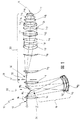
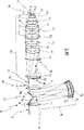
図1は、物体平面12に配置されるパターン(図示せず)を像平面14内に結像するための、一般参照符号10を付けたマイクロリソグラフィ投影対物レンズを示している。
投影対物レンズ10は、第1対物レンズ部16、第2対物レンズ部18、および第3対物レンズ部20を有している。
Illustrative embodiments of the invention are illustrated in the drawings and will be described in more detail below with reference thereto.
FIG. 1 shows a microlithographic projection objective with a
The
第1対物レンズ部16は、ディオプトリックであり、かつレンズL1によって形成されている。
第2対物レンズ部18は、カタディオプトリックであり、かつレンズL2、L3および凹面鏡M2を有している。
第3対物レンズ部20は、ディオプトリックであり、かつレンズL4〜L17および端部平面L18を有している。
The first
The second
The third
図1に示すように、第2対物レンズ部18における光伝搬方向は、第1対物レンズ部12および第3対物レンズ部20における光伝搬方向と異なっている。この結果、投影対物レンズ10は、2つの折畳み鏡M1およびM3によって示される、例示的な実施形態において形成されるビーム偏向装置22を有している。折畳み鏡M1は、第1対物レンズ部16から鏡M2に向かって第2対物レンズ部内18に入る光ビームを偏向し、第2折畳み鏡M3は、第2対物レンズ部18から第3対物レンズ部20内に入る光ビームを偏向する。
As shown in FIG. 1, the light propagation direction in the second
第3対物レンズ部20における光伝搬方向は、第1対物レンズ部16における光伝搬方向に対応する。
光を透過しないシールド24はビーム偏向装置22の領域に、第1対物レンズ部16から第3対物レンズ部20への直接の光漏れ、たとえばレンズL1の表面からの反射を回避するために設けられている。特にシールド24は、第2対物レンズ部18を抜かして第1対物レンズ部16から第3対物レンズ部20内へ光が漏れるのを防ぎ、すなわち、光がレンズL2,L3を通過しないで鏡M2で反射されるのを防ぐ。
The light propagation direction in the third
すでに述べたように、図1および図2に図示するように、ビーム偏向装置22はその反射表面が互いに対してある角度で配置される2つの折畳み鏡M1およびM3によって形成されている。2つの反射表面、すなわち鏡M1およびM3は、互いに対してある角度(ここではほぼ90度)で行われるビーム偏向に従って配置され、シールド24は、第2対物レンズ部分18の方向において2つの鏡M1およびM3の角頂点から延びている。
As already mentioned, as illustrated in FIGS. 1 and 2, the
シールド24は、板26、たとえば、用いられる光の波長領域において吸収する金属板である。さらに、この板には吸収層を設けることができる。しかしながら、金属板の代わりに、吸収性となるように被覆されていてもよい他の材料から作られる素子を用いることもできる。図2によれば、2つの鏡M1およびM3は板26をそこに位置決めすることができ、かつ有効な光をマスクしないように、角頂点で互いにわずかに間隔が開けられている。
The
シールド24は、結像ビーム経路、すなわち、結像のために用いられる光のビーム経路を制限しないように設計され、配置されている。第2対物レンズ部18内への光伝搬の方向における板26の位置決めおよび範囲は、相応して設計される。
さらなるシールド28は、投影対物レンズ10における迷光のレベルをさらに減少させるために、第3対物レンズ部20において作成される中間像30の領域に配置されている。
The
The
シールド28は、迷光の通過を減少させる迷光絞り32を備えている。しかしながら、迷光絞り32は、結像ビーム経路を制限するのに役立つシステム開口絞り34と区別される。対照的に、迷光絞り32は、結像ビーム経路を制限しないが、投影対物レンズ10における迷光部分を減少させるのに役立つ。
好ましくは、シールド24および/またはシールド28を、活性断面に対して位置調整および/または可変設定することができると規定されている。たとえば迷光を減少させるために、シールド24の板26は、板26の最適位置および最適活性断面を設定することができるように可動でありかつ可変長であってよい。迷光シールドの活性断面の位置調整および/または設定は、好ましくは、対物レンズの開口および/または用いられる物体視野の大きさの照明モード(設定)に応じて行われる。
The
Preferably, it is defined that the
たとえば、迷光絞り32の場合には、迷光絞り32の開口部断面を変更および/または迷光絞り32が最適位置となるように位置調整することができるように構成すると規定することができる。
投影対物レンズ10における迷光のレベルを減少させるために、投影対物レンズ10にさらなるシールドを設けることができるのは自明なことである。
For example, in the case of the stray
It is self-evident that a further shield can be provided on the
好適に装着されたシールドによって、約30%以上の迷光の減少が、て可能な範囲内にあることが明らかになってきた。
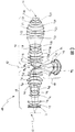
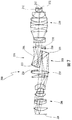
図3は、物体平面42に配置されるパターン(図示せず)を像平面44に結像する、さらなるマイクロリソグラフィ投影対物レンズ40を図示している。
投影対物レンズ40は、設計のより正確な説明のために参照が可能な上記特許文献2に開示されている。
It has been found that with a suitably fitted shield, a stray light reduction of about 30% or more is within the possible range.
FIG. 3 illustrates a further
The
投影対物レンズ10と同様、投影対物レンズ40は、カタディオプトリック投影対物レンズであり、投影対物レンズ40は、板L1およびレンズL2〜L11を有する第1対物レンズ部46、レンズL12,L13および鏡M2を有する第2対物レンズ部48、およびレンズL14〜L28を有する第3対物レンズ部50を有している。
図1の例示的な実施形態の場合におけるように、折畳み鏡M1および折畳み鏡M3を備えるビーム偏向装置52は、第1対物レンズ部46と第2対物レンズ部48との間または第2対物レンズ部48と第3対物レンズ部50との間に配置される。
Similar to the
As in the exemplary embodiment of FIG. 1, the
投影対物レンズ40の場合もまた、偏向装置52の領域には、投影対物レンズ10のシールド24に相当するシールド54が設けられており、迷光が第1対物レンズ部46から第3対物レンズ部50内へ漏れないようにする効果がある。
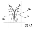
ビーム偏向装置52の領域における投影対物レンズ40の拡大断面を、図3Aに図示する。シールド54に加えて、投影対物レンズ40の場合には、投影対物レンズ40の中間像の領域にそれぞれ配置されるさらなるシールド54aおよびさらなるシールド54bが設けられている。シールド54および54bは、迷光絞りとして設計されている。
Also in the case of the
An enlarged cross section of the
その他の点については、シールド54の構成に関して図1のシールド24の説明を参照することが可能であり、すなわちシールド54の構成はシールド24の構成に対応している。
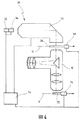
図4の一般参照符号60は、たとえば、投影対物レンズ10が用いられる投影露光機を示している。投影露光機は、レーザの帯域幅を狭める装置64を有するレーザ光源62を備えている。照明システム66は、下流の投影対物レンズ10のテレセントリック要求に適合している、大きく、境界がはっきりしており、かつ非常に均質に照射された像視野を作成する。照明システム66は、照明モードを選択する装置を有し、かつ該照明システムを、たとえば、さまざまな種類のコヒーレンスを有する従来の照明、環状視野照明、および双極子または四重極照明間で切り替えることができる。照明システムの後に配置されるのは、マスク70が投影対物レンズ10の物体平面12に存在し、かつこの平面内で走査動作のために移動することができるようにマスク70を保持しかつ操作する装置68である。装置68は同様に走査駆動装置を備えている。
For other points, it is possible to refer to the description of the
A
物体平面12に続くのは、マスク70の像を感光層で被覆され、かつ投影対物レンズ10の像平面14に配置される基板、つまりウエハ72上に縮小して投影する投影対物レンズ10である。基板、つまりウエハ72は、マスク70と同期して該ウエハを移動させるためにスキャナー駆動装置を備える装置74によって保持されている。すべてのシステムは、制御ユニット74によって制御される。そのようなシステムの設計は、それらの動作モードと同様に、それ自体公知であり、それゆえここではより詳細に説明しない。
Following the
半導体部品および他の微細構造アセンブリを製造する方法の場合、マスク70には規定パターン(図示せず)が設けられる。照明装置66を用いて、マスク70はレーザ62から所定波長の紫外光で照射される。この場合、文献から十分周知であるさまざまな照明モードを設定することが可能である。次に、マスク70のパターンは、投影対物レンズ10を用いて、基板、つまりウエハ72上にかつ投影対物レンズ10の像平面14内に結像される。この場合、さまざまな開口の開口部を設定することができる。
For methods of manufacturing semiconductor components and other microstructured assemblies,
図5は、図1の投影対物レンズ10をもう一度示し、偽光抑制のさらなる手段が投影対物レンズ10に設けられている。
偽光を抑制するために以下で説明するシールドは、これらのシールドが割り当てられる光学部品のそれぞれの未使用表面領域をマスクするのに役に立つ。したがって、これらのシールドの機能は、すでに上述し、かつ第2対物レンズ18を抜かして第1対物レンズ部16から第3対物レンズ部20内へ光が伝搬しないようにする機能があるシールド24とは異なっている。
FIG. 5 shows the
The shields described below to suppress spurious light serve to mask the unused surface area of each of the optical components to which these shields are assigned. Therefore, the functions of these shields have already been described above, and the
図5によれば、レンズL5は、対物レンズ12を像平面14内に結像する結像ビーム経路によって用いられない表面領域UL5を有している。偽光を抑制するためにレンズL5の未使用表面領域UL5をマスクするシールド80は、この未使用表面領域UL5に割り当てられる。シールド80は、特に結像に用いられる光の波長を吸収するコーティング82の形態で設計される。シールド80の吸光度は、この場合少なくとも約95%であり、好ましくは少なくとも約98%である。しかしながら、コーティング82の形態のシールド80は、代替的にまたは付加的に反射特性を持つこともできる。
According to FIG. 5, the lens L 5 has a surface area UL 5 that is not used by the imaging beam path for imaging the
シールド80は、さらに好ましくは、その上に堆積される汚染物質、たとえば炭化水素を分解するために光触媒特性を有する。それによって、光学部品間に位置決めされる投影対物レンズ10の気層は、それによってこれらの汚染物質が除かれる。
レンズL5は、視野平面の近傍、具体的には中間像30の近傍に位置決めされている。しかしながら、迷光絞り32と対照してみると、シールド80はレンズL5に直接割り当てられ、かつコーティング82の形態でレンズL5に直接塗布されている。
The
Lens L 5 is near the field plane, specifically are positioned in the vicinity of the
偽光を抑制するためのシールドの割り当に好適なさらなる光学部品は、結像ビーム経路によって用いられない表面領域UL6を有するレンズL6である。レンズL6は、やはりレンズL6の光学活性表面上にコーティング86の形態で塗布されるシールドが同様に割り当てられている。
像平面14に直接隣接している最後のレンズ素子L18は、図5に図示するように、結像ビーム経路によって用いられない表面領域UL18を有する。コーティング90から形成されるさらなるシールド88は、同様に、両側で最後のレンズ素子L18に割り当てられる。最後のレンズ素子L18の場合には、コーティング90は、有効な光がコーティングの形態のシールド88の開口部を像平面14までコーティングの形態で貫通することができるように、その上に環状で形成される。
A further optical component suitable for assigning a shield to suppress spurious light is a lens L 6 having a surface area U L6 that is not used by the imaging beam path. Lens L 6 is similarly assigned a shield that is also applied in the form of a
The last lens element L 18 immediately adjacent to the
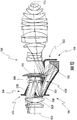
図6は、図5を参照して前述したように、偽光抑制の手段が提供されるさらなるカタディオプトリック投影対物レンズ100を示している。投影対物レンズ100は、設計のより正確な説明について参照してもよい上記特許文献3に開示されている。
投影対物レンズ100は、像平面102内に物体平面101を結像する。投影対物レンズ100は、物体平面101と像平面102との間に、カタディオプトリック対物レンズ部105に位置決めされ、その上流に屈折対物レンズ部106が位置決めされ、かつその下流に屈折対物レンズ部107が位置決めされる、2つの中間像103および104を生成する。
FIG. 6 shows a further
The
レンズおよび2つの鏡を備える投影対物レンズ100の複数の光学部品のなかには、少なくとも一つの光学作用表面が、投影対物レンズの動作中、物体平面101を像平面102内に結像するための結像ビーム経路によって用いられない表面領域を有するものがある。これらの光学部品は、シールドに直接割り当てられるのに好適である。
コーティング112の形態のシールドに割り当てられるレンズ108は、これらの光学部品に属している。コーティング112は、像側ではレンズ108の光学作用表面に塗布され、かつ好ましくは、図5を参照してすでに説明したコーティング82、86および90の特性も同様に有している。
Among the optical components of the
The
投影対物レンズ100の鏡114は、同様に、光によって用いられずかつ遮蔽コーティング116が設けられる表面領域を有している。
鏡114に直接隣接するレンズ118は、結像ビーム経路によって用いられない表面領域を有し、かつ同様に遮蔽コーティング120が設けられる光学作用表面を有している。
最後に、最後のレンズ素子122には、同様に遮蔽コーティング124が設けられる。
The
The
Finally, the
記載したようなシールドが割り当てられる上述した光学部品は、すべて視野の近くにあり、レンズ108,118および鏡116は、中間像103および104の近傍に配置され、一方最後のレンズ素子122は、像平面102の近傍に配置されている。このような近視野光学部品は、特に偽光を抑制する目的で、それぞれの光学部品の光学作用表面のそれぞれの未使用表面領域をマスクするシールドが直接割り当てられるのに好適である。
All of the optical components described above that are assigned a shield as described are near the field of view, and the
図7はさらなる投影対物レンズ200を示し、その場合偽光を抑制するために、図5および図6に類似の手段が提供される。投影対物レンズ200は、同様に上記特許文献3に開示されている。
投影対物レンズ200は、物体平面201を像平面202内に結像する複数の光学部品を有している。投影対物レンズ200は、屈折第1対物レンズ部210、2つの鏡221および222から形成されるカトプトリック(反射)第2対物レンズ部220、および屈折第3対物レンズ部230を有している。
FIG. 7 shows a
The
中間像203および中間像204は、カトプトリック対物レンズ部220に生成される。
第1対物レンズ部210の最後のレンズ232には、遮蔽コーティング234が設けられる。第3対物レンズ部230の第1レンズ236には、遮蔽コーティング238が設けられる。最後のレンズ素子240には、遮蔽コーティング242が設けられる。
The
The
ここでもやはり、近視野光学部品は、偽光を抑制する手段のために選択されてきた。
最後に、図8は、さらなる投影対物レンズ300を示し、その場合偽光を抑制する手段が提供される。投影対物レンズ300は、同様に上記特許文献3に開示されている。
投影対物レンズ部300は、物体平面301を像平面302内に結像するカタディオプトリック投影対物レンズである。投影対物レンズ300は、屈折第1対物レンズ部310、カトプリック第2対物レンズ部320、および屈折第3対物レンズ部330を有している。
Again, near-field optics have been selected for a means to suppress spurious light.
Finally, FIG. 8 shows a
The
カトプリック対物レンズ部320は、4つの鏡306,307,321および322を有している。
投影対物レンズ300は、カトプリック対物レンズ部320に中間像を生成する。
視野の近くの位置に位置決めされるレンズ332は、結像ビーム経路によって用いられない表面領域を有し、かつ該レンズには遮蔽コーティング334が設けられる。さらなるレンズ336には、遮蔽コーティング338が設けられ、かつさらなるレンズ340には、遮蔽コーティング342が設けられる。
The catopric
The
A
最後のレンズ素子344には、同様に遮蔽コーティング346が設けられる。
特にこのような投影対物レンズ部が液浸対物レンズとして設計される場合、最後のレンズ素子、たとえばレンズ素子344には、好ましくは、最後のレンズ素子344を浸液による劣化から保護するコーティングが設けられる。このような場合、この保護コーティングを、特に遮蔽作用を用いて設計することも可能であり、すなわち保護層はそのとき最後のレンズ素子344を保護するだけでなく、偽光を抑制するのにも役立つ。
The last lens element 344 is similarly provided with a shielding
Particularly when such a projection objective is designed as an immersion objective, the last lens element, for example the lens element 344, is preferably provided with a coating that protects the last lens element 344 from degradation by immersion liquid. It is done. In such a case, this protective coating can also be designed in particular with a shielding action, i.e. the protective layer not only protects the last lens element 344 but also suppresses false light. Useful.
図9〜図11は投影対物レンズを示し、その場合本発明にしたがって偽光抑制の手段が提供される。
以下で説明する投影対物レンズの場合に行う偽光抑制の手段は、次の原理に基づいている。少なくとも一つの鏡を有する投影対物レンズの場合には、パターンを像平面内に結像するために用いることができる結像ビーム経路は、少なくとも一つの鏡の領域において、互いに対して斜めに走行し、かつ重複領域において少なくとも部分的に互いに重複するビーム経路セグメントを有することができる。ビーム経路セグメントは、重複領域の外部の間隙または自由空間によって互いに間隔が開けられている。シールドは、この場合、偽光を抑制するために間隙に配置される。このような投影対物レンズが、ビーム経路セグメント間または光束間に多数のこのような間隙または自由空間を有する場合、好ましくは、これらの自由空間または間隙が偽光の伝搬にもはや利用できないように、たとえば、一つ以上の迷光絞りの形態でこれらの自由空間の各々にシールドを導入することが可能である。このようにして偽光を有効に抑制することができる。
9 to 11 show a projection objective, in which case means for suppressing false light are provided according to the invention.
The means for suppressing false light performed in the case of the projection objective described below is based on the following principle. In the case of a projection objective with at least one mirror, the imaging beam paths that can be used to image the pattern in the image plane run obliquely relative to each other in the region of at least one mirror. And at least partially overlapping beam path segments in the overlap region. The beam path segments are spaced from each other by a gap or free space outside the overlap region. In this case, the shield is placed in the gap to suppress false light. If such a projection objective has a large number of such gaps or free spaces between beam path segments or beams, preferably such free spaces or gaps are no longer available for the propagation of spurious light, For example, it is possible to introduce a shield into each of these free spaces in the form of one or more stray light stops. In this way, false light can be effectively suppressed.
図9は、物体平面402と像平面404との間に、第1カタディオプトリック対物部分406および第2ディオプトリック対物部分408を有する投影対物レンズ400を示している。投影対物レンズ400は、上記特許文献4の図5に記載されている。
カタディオプトリック対物レンズ部406は、第1鏡410および第2鏡412を有している。
FIG. 9 shows a
The catadioptric objective lens unit 406 includes a
偽光の伝搬を抑制するために、第1シールド414は迷光絞り416の形態で設けられ、かつ第2シールド418は迷光絞り420の形態で設けられている。仕切のない設計の迷光絞りの部分としても設計してもよい迷光絞り416および420は、図9からわかるように、鏡410および412の近傍に位置決めされ、迷光絞り416は鏡410と鏡412との間の領域に延びている。迷光絞り420は、鏡410と鏡412との間の領域に突出する部分422も有している。迷光絞り416および420は、光束間の自由空間が2つの鏡410および412の間で埋められるように設置されている。迷光絞り416および420の、光学軸440に対して半径方向に延びている部分416aおよび420aにより、偽光が、後者すなわち迷光絞り416および420を抜かしつつ物体平面402から第1鏡410に沿ってまたは第2鏡412に沿って通過しないようにし、かつレンズが第2対物レンズ部408を像平面404上に結像しないようにする。
In order to suppress the propagation of false light, the
図10は、同様に、上記特許文献4の図9に示され、かつ該文献に記載される投影対物レンズ500を示している。
投影対物レンズ500は、物体平面502と像平面504との間に、投影対物レンズ500が構成される、投影対物レンズ500の2つの対物レンズ部514および516に属する4つの鏡506,508,510および512を有している。
FIG. 10 similarly shows the
The
シールド518,520および522は、投影対物レンズ500の場合には、偽光の伝搬を抑制するために設けられる。シールド518は、一つのサブアセンブリとして設計することができる部分526,528および530を有する迷光絞り524であり、適切な通路が、結像のために設けられる結像光用迷光絞り424に設けられている。シールド520および522は、同様に結像光の光束間の自由空間に配置される迷光絞りの形態で設計される。
In the case of the
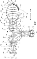
最後に、図11は、上記特許文献4の図14に図示され、かつ該文献に記載される投影対物レンズ600を示している。
投影対物レンズは、物体平面602と像平面604との間、具体的には伝搬の方向に第1鏡606、第2鏡608、第3鏡610、第4鏡612、第5鏡614、および第6鏡616の合計6つの鏡を有している。
Finally, FIG. 11 shows the
The projection objective includes a
投影対物レンズ600における偽光の伝搬を防ぐために、多数のシールドが、鏡606〜616の領域における迷光絞り618,620,622および624の形態で配置され、これらもやはり同様に偽光の伝搬にさからって結像のために用いられる光束間の自由空間を遮蔽する。
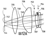
図12は、物体平面702に配置されるパターンを像平面704内に結像するマイクロリソグラフィ投影対物レンズ700の他の実施形態を示している。
In order to prevent the propagation of spurious light in the
FIG. 12 shows another embodiment of a
投影対物レンズ700は、複数の光学部品705〜733を備え、光学部品713,717および718は鏡であり、光学部品705〜733のうちの残りの部品はレンズである。
投影対物レンズ700は、第1開口絞り738が配置される第1瞳孔平面736をさらに有している。断面で調整可能である開口絞り738は、投影対物レンズ700のシステムまたは設計開口を規定する。第2瞳孔平面740は、光学部品707と光学部品708との間に存在する。
The
The
図12の図示において、物体平面702のパターンの照射領域を説明する、物体平面702の2つの視野点742および744を示す。光線は、視野点742および744から光学部品705〜733を伝搬し、領域746の像平面704に達する。領域746の像平面746に達する光線は、物体平面702に配置されるパターンを物体平面704内に結像するために用いられる。
In the illustration of FIG. 12, two
図12に示すように、他の光線、たとえば同じく視野点742から始まる光線749の開口よりも大きい開口で始まる、物体面702の視野点742からの光線748がある。光線748は、オーバ開口光線と呼ばれる。
図12Aは、4つの第1光学部品705〜708を拡大して示し、視野点742および744からの光線をより詳細に示している。
As shown in FIG. 12, there are other rays, for example,
FIG. 12A shows an enlarged view of the four first optical components 705-708, showing the rays from the field points 742 and 744 in more detail.
実際には小さな光線束であるオーバ開口光線748は、結像に用いられる光線から部分的に分離され、結像に用いられる光線から部分的に分離される投影対物レンズ700を伝搬し、一部は結像のために用いられる光線から分離されず、後者の光線は領域746の像平面704に達する。その代わりに、オーバ開口光線は領域750の像平面704に達する。オーバ開口光線748は、特に像平面704に不均一視野を生成することによって結像を妨げる。
The
オーバ開口光線748が像平面704に達しないようにするために、システム開口絞り738に加えて、少なくとも第2開口絞りが以下に説明するように、投影対物レンズ700に設けられる。
第2開口絞りは、好ましくは、投影対物レンズ700のある位置に配置され、そこでオーバ開口光線748は、結像に役に立つ「通常」光線から分離される。このような位置は、たとえば、光学部品706と光学部品707との間の空間(図12Aの矢印752を参照)および/または光学部品707と708との間の位置(図12Aの矢印754を参照)であってもよい。後者の場合、光学部品707と光学部品708との間の空間が小さいため、第2開口絞りを、露光作業に用いられる光に対して非透過的である光学部品707または708上にコーティング756によって形成することができる。コーティングを、たとえば、光学部品707の表面のそれぞれの部分を黒くすることによって形成することができる。
In order to prevent the
The second aperture stop is preferably located at a position on the
矢印752によって示す位置では、少なくとも一つの第2開口絞りを、オーバ開口光線748を遮蔽するまたはマスクするための適切な遮蔽特性を有する板によって形成することができる。
オーバ開口光線748をマスクするための少なくとも第2開口絞りを配置するのに非常に好適である他の位置は、投影対物レンズ700の領域758にあり、そこでオーバ開口光線748は、結像に用いられ、かつ光学軸に対して最も高い光線である光線760から大幅に分離される。「通常」光線よりはるかに大きい光線748が部品724から出る場合、強く屈折されるまたは収差があることが、図12から分かる。
In the position indicated by
Another position that is very suitable for positioning at least a second aperture stop for masking over
たとえば、第2すなわちさらなる開口絞り762を、光学部品725と光学部品726との間および/または光学部品726と727との間等に配置することができる。
第2すなわちさらなる開口絞り762の位置は、好ましくは、システム開口738からの開口絞り762の距離Lが0.5D<L<2Dであるように選択され、式中Dはこの領域の光学部品の最大直径である。
For example, a second or
The position of the second or
たとえば、矢印752によって示す位置に配置した際の少なくとも一つの第2開口絞り、すなわち開口絞り762は、好ましくは固定開口絞りであり、かつシステム開口を規定する開口絞り738は、その有効断面に関して調整可能である。
投影対物レンズ700は、第1瞳孔平面738と第2瞳孔平面740との間に少なくとも一つの中間像平面を有している。さらに、投影対物レンズ700の光学部品705〜733の少なくも一つは、非球面光学作用表面を有していてもよい。特に非球面作用表面を持つ部品を有する投影対物レンズでは、オーバ開口光線748のようなオーバ開口光線は、非球面部品がない投影対物レンズにおけるように大きな収差がある。したがって、少なくとも第2開口絞りを非球面部品を有するそのような投影対物レンズに設けることは特に有利である。
For example, at least one second aperture stop, or
図12を参照して説明したような少なくとも第2開口絞りを、適切であれば図1〜図11に示す投影対物レンズのうちの任意のものにも設けることができる。逆に、図1〜図11に関して説明した偽光を遮蔽するシールドを、投影対物レンズ700内にも設けることができる。
At least the second aperture stop as described with reference to FIG. 12 can be provided on any of the projection objectives shown in FIGS. Conversely, a shield for shielding the false light described with reference to FIGS. 1 to 11 can also be provided in the
Claims (53)
前記第2対物レンズ部は、前記第1対物レンズ部における光伝搬方向および前記第3対物レンズ部における光伝搬方向と異なる光伝搬方向を規定し、
前記第1対物レンズ部と前記第2対物レンズ部との間および前記第2対物レンズ部と前記第3対物レンズ部との間に少なくとも一つのビーム偏向装置をさらに備え、
少なくとも一つのシールドが、前記第1対物レンズ部から第3対物レンズ部内への直接光漏れが少なくとも減少するようにして前記ビーム偏向装置の領域に配置される、マイクロリソグラフィ投影対物レンズ。 A microlithography projection objective that images a pattern arranged in an object plane in an image plane, comprising a first objective lens part, a second objective lens part, and at least one third objective lens part,
The second objective lens unit defines a light propagation direction different from a light propagation direction in the first objective lens unit and a light propagation direction in the third objective lens unit,
And further comprising at least one beam deflecting device between the first objective lens unit and the second objective lens unit and between the second objective lens unit and the third objective lens unit,
A microlithographic projection objective, wherein at least one shield is arranged in the region of the beam deflection device in such a way that direct light leakage from the first objective part into the third objective part is at least reduced.
前記複数の光学部品のうち、前記投影対物レンズの作動中、前記パターンを前記像平面内に結像する前記結像ビーム経路に用いられない第1表面領域を有する少なくとも一つの第1光学作用表面を持った少なくとも一つの第1光学部品が存在し、
前記少なくとも一つの第1光学作用表面には、偽光を抑制するために前記第1光学作用表面の、前記結像ビーム経路に用いられない前記第1表面領域をマスクする少なくとも一つの第1シールドが割り当てられる、投影対物レンズ。 A microlithographic projection objective for imaging a pattern arranged in an object plane in an image plane, comprising a plurality of optical components each having at least one optically active surface;
Of the plurality of optical components, at least one first optical working surface having a first surface region not used for the imaging beam path for imaging the pattern in the image plane during operation of the projection objective. There is at least one first optical component with
The at least one first optical working surface has at least one first shield that masks the first surface region of the first optical working surface that is not used in the imaging beam path to suppress spurious light. Is assigned a projection objective.
前記パターンを前記像平面に結像するために用いることができる結像ビーム経路は、前記少なくとも一つの鏡の領域において、互いに対して斜めに延び、走行しかつ重複領域で少なくとも部分的に互いに重複し、かつ前記重複領域の外部で間隙によって互いに間隔が開けられているビーム経路セグメントを有し、
偽光を抑制する少なくとも一つのシールドが前記間隙に配置される、投影対物レンズ。 A microlithographic projection objective for imaging a pattern arranged in an object plane in an image plane, comprising a plurality of optical components including at least one mirror;
Imaging beam paths that can be used to image the pattern in the image plane extend obliquely relative to each other in the region of the at least one mirror and run and at least partially overlap each other in the overlapping region. And beam path segments spaced from each other by a gap outside the overlap region,
A projection objective, wherein at least one shield for suppressing spurious light is arranged in the gap.
システム開口を規定する第1開口絞りは、前記第1瞳孔平面の近くに少なくとも配置され、少なくとも第2開口絞りをさらに備える、投影対物レンズ。 A microlithographic projection objective that images a pattern placed in an object plane into an image plane, comprising a plurality of optical components, a first pupil plane and at least a second pupil plane,
A projection objective, wherein a first aperture stop defining a system aperture is at least disposed near the first pupil plane and further comprises at least a second aperture stop.
Applications Claiming Priority (3)
| Application Number | Priority Date | Filing Date | Title |
|---|---|---|---|
| US68678405P | 2005-06-02 | 2005-06-02 | |
| US79061606P | 2006-04-10 | 2006-04-10 | |
| PCT/EP2006/004876 WO2006128613A1 (en) | 2005-06-02 | 2006-05-23 | Microlithography projection objective |
Related Child Applications (2)
| Application Number | Title | Priority Date | Filing Date |
|---|---|---|---|
| JP2012139049A Division JP5591875B2 (en) | 2005-06-02 | 2012-06-20 | Microlithography projection objective |
| JP2014146972A Division JP6050288B2 (en) | 2005-06-02 | 2014-07-17 | Microlithography projection objective |
Publications (2)
| Publication Number | Publication Date |
|---|---|
| JP2008542829A true JP2008542829A (en) | 2008-11-27 |
| JP2008542829A5 JP2008542829A5 (en) | 2009-07-09 |
Family
ID=36782280
Family Applications (9)
| Application Number | Title | Priority Date | Filing Date |
|---|---|---|---|
| JP2008513975A Pending JP2008542829A (en) | 2005-06-02 | 2006-05-23 | Microlithography projection objective |
| JP2012139049A Expired - Fee Related JP5591875B2 (en) | 2005-06-02 | 2012-06-20 | Microlithography projection objective |
| JP2014092743A Expired - Fee Related JP5830129B2 (en) | 2005-06-02 | 2014-04-28 | Microlithography projection objective |
| JP2014146972A Expired - Fee Related JP6050288B2 (en) | 2005-06-02 | 2014-07-17 | Microlithography projection objective |
| JP2016000839A Expired - Fee Related JP6182224B2 (en) | 2005-06-02 | 2016-01-06 | Microlithography projection objective |
| JP2016223867A Pending JP2017040939A (en) | 2005-06-02 | 2016-11-17 | Microlithography projection objective lens |
| JP2017100697A Withdrawn JP2017138632A (en) | 2005-06-02 | 2017-05-22 | Microlithography projection objective lens |
| JP2017151387A Withdrawn JP2017201430A (en) | 2005-06-02 | 2017-08-04 | Microlithography projection objective lens |
| JP2018241495A Withdrawn JP2019070831A (en) | 2005-06-02 | 2018-12-25 | Microlithography projection objective |
Family Applications After (8)
| Application Number | Title | Priority Date | Filing Date |
|---|---|---|---|
| JP2012139049A Expired - Fee Related JP5591875B2 (en) | 2005-06-02 | 2012-06-20 | Microlithography projection objective |
| JP2014092743A Expired - Fee Related JP5830129B2 (en) | 2005-06-02 | 2014-04-28 | Microlithography projection objective |
| JP2014146972A Expired - Fee Related JP6050288B2 (en) | 2005-06-02 | 2014-07-17 | Microlithography projection objective |
| JP2016000839A Expired - Fee Related JP6182224B2 (en) | 2005-06-02 | 2016-01-06 | Microlithography projection objective |
| JP2016223867A Pending JP2017040939A (en) | 2005-06-02 | 2016-11-17 | Microlithography projection objective lens |
| JP2017100697A Withdrawn JP2017138632A (en) | 2005-06-02 | 2017-05-22 | Microlithography projection objective lens |
| JP2017151387A Withdrawn JP2017201430A (en) | 2005-06-02 | 2017-08-04 | Microlithography projection objective lens |
| JP2018241495A Withdrawn JP2019070831A (en) | 2005-06-02 | 2018-12-25 | Microlithography projection objective |
Country Status (6)
| Country | Link |
|---|---|
| US (4) | US20090115986A1 (en) |
| EP (1) | EP1886190B1 (en) |
| JP (9) | JP2008542829A (en) |
| KR (7) | KR101483791B1 (en) |
| CN (1) | CN101297243B (en) |
| WO (1) | WO2006128613A1 (en) |
Cited By (2)
| Publication number | Priority date | Publication date | Assignee | Title |
|---|---|---|---|---|
| JP2008028369A (en) * | 2006-06-21 | 2008-02-07 | Canon Inc | Projection optical system |
| JP2011248366A (en) * | 2010-05-19 | 2011-12-08 | Carl Zeiss Smt Gmbh | Projection objective having aperture stop |
Families Citing this family (18)
| Publication number | Priority date | Publication date | Assignee | Title |
|---|---|---|---|---|
| JP2008542829A (en) | 2005-06-02 | 2008-11-27 | カール・ツァイス・エスエムティー・アーゲー | Microlithography projection objective |
| DE102006045075A1 (en) | 2006-09-21 | 2008-04-03 | Carl Zeiss Smt Ag | Controllable optical element |
| JP4267668B2 (en) * | 2007-03-08 | 2009-05-27 | 株式会社日立製作所 | 3D image display device |
| JP4310349B2 (en) * | 2007-04-20 | 2009-08-05 | キヤノン株式会社 | Exposure apparatus and device manufacturing method |
| DE102007022895B9 (en) * | 2007-05-14 | 2013-11-21 | Erich Thallner | Device for transferring structures provided in a mask onto a substrate |
| WO2008138560A1 (en) | 2007-05-14 | 2008-11-20 | Carl Zeiss Smt Ag | Projection lens and projection lighting system for microlithography |
| DE102008001800A1 (en) * | 2007-05-25 | 2008-11-27 | Carl Zeiss Smt Ag | Projection lens for microlithography, microlithography projection exposure apparatus with such a projection lens, microlithographic manufacturing method for components as well as produced by this method component |
| US20080297740A1 (en) * | 2007-05-29 | 2008-12-04 | Phong Huynh | Projection system and method of use thereof |
| US8208127B2 (en) | 2007-07-16 | 2012-06-26 | Carl Zeiss Smt Gmbh | Combination stop for catoptric projection arrangement |
| JP5579063B2 (en) | 2007-08-24 | 2014-08-27 | カール・ツァイス・エスエムティー・ゲーエムベーハー | Controllable optical element, method of operating optical element with thermal actuator, and projection exposure apparatus for semiconductor lithography |
| DE102008001694A1 (en) * | 2008-05-09 | 2009-11-12 | Carl Zeiss Smt Ag | Projection optics for microlithography |
| KR20120018196A (en) | 2009-05-16 | 2012-02-29 | 칼 짜이스 에스엠테 게엠베하 | Projection exposure apparatus for semiconductor lithography comprising an optical correction arrangement |
| DE102009035788B4 (en) | 2009-07-31 | 2011-06-30 | Carl Zeiss Laser Optics GmbH, 73447 | Optical arrangement in an optical system, in particular a lighting device |
| DE102009037077B3 (en) * | 2009-08-13 | 2011-02-17 | Carl Zeiss Smt Ag | Catadioptric projection lens |
| WO2014097859A1 (en) * | 2012-12-18 | 2014-06-26 | 株式会社ニコン | Substrate processing device, device manufacturing system and method for manufacturing device |
| DE102017204619A1 (en) | 2016-04-05 | 2017-10-05 | Carl Zeiss Smt Gmbh | Projection exposure method, projection objective and projection exposure apparatus for microlithography |
| DE102017211902A1 (en) | 2017-07-12 | 2018-08-02 | Carl Zeiss Smt Gmbh | Projection objective for a projection exposure apparatus for microlithography |
| WO2020009764A1 (en) * | 2018-07-03 | 2020-01-09 | Applied Materials, Inc. | Pupil viewing with image projection systems |
Citations (8)
| Publication number | Priority date | Publication date | Assignee | Title |
|---|---|---|---|---|
| JPS6048015A (en) * | 1983-08-27 | 1985-03-15 | Ricoh Co Ltd | Image forming optical device |
| JPS6053926A (en) * | 1983-09-03 | 1985-03-28 | Ricoh Co Ltd | Optical device for image formation |
| JPS61219018A (en) * | 1985-03-25 | 1986-09-29 | Ricoh Co Ltd | Optical image forming device |
| JP2000010005A (en) * | 1998-06-17 | 2000-01-14 | Nikon Corp | Catadioptric projection exposing device |
| JP2000242096A (en) * | 1999-02-22 | 2000-09-08 | Minolta Co Ltd | Image forming device and method for applying transfer voltage |
| JP2002107630A (en) * | 2000-08-01 | 2002-04-10 | Carl Zeiss Stiftung Trading As Carl Zeiss | Micro-lithographic projection optical system using six reflection mirrors |
| JP2003043362A (en) * | 2001-05-22 | 2003-02-13 | Carl Zeiss Semiconductor Manufacturing Technologies Ag | Catadioptric reduction lens |
| JP2005504337A (en) * | 2001-09-20 | 2005-02-10 | カール・ツァイス・エスエムティー・アーゲー | Catadioptric reduction lens |
Family Cites Families (71)
| Publication number | Priority date | Publication date | Assignee | Title |
|---|---|---|---|---|
| US3606535A (en) * | 1968-02-17 | 1971-09-20 | Ricoh Kk | Device for rectifying uneven distribution of illumination intensity in a slit exposure mechanism |
| JPS572017A (en) * | 1980-06-06 | 1982-01-07 | Ricoh Co Ltd | Reflection type equal magnification image forming element |
| US4776683A (en) * | 1985-03-25 | 1988-10-11 | Ricoh Company, Ltd. | Optical imaging device |
| JPH0827430B2 (en) * | 1988-03-22 | 1996-03-21 | 株式会社ニコン | Two-group zoom lens |
| JPH0684746A (en) * | 1992-03-09 | 1994-03-25 | Hitachi Ltd | Projection aligner and formation of pattern |
| JP3201027B2 (en) * | 1992-12-22 | 2001-08-20 | 株式会社ニコン | Projection exposure apparatus and method |
| JPH06235863A (en) | 1993-02-12 | 1994-08-23 | Nikon Corp | Cata-dioptric system |
| JP3747958B2 (en) * | 1995-04-07 | 2006-02-22 | 株式会社ニコン | Catadioptric optics |
| JP3029177B2 (en) * | 1994-04-26 | 2000-04-04 | キヤノン株式会社 | Zoom lens with flare cut aperture |
| US6512631B2 (en) * | 1996-07-22 | 2003-01-28 | Kla-Tencor Corporation | Broad-band deep ultraviolet/vacuum ultraviolet catadioptric imaging system |
| JPH09197277A (en) * | 1996-01-23 | 1997-07-31 | Minolta Co Ltd | Zoom lens |
| JP3517563B2 (en) * | 1997-09-30 | 2004-04-12 | キヤノン株式会社 | Semiconductor exposure apparatus and semiconductor device manufacturing process using the same |
| JP3445120B2 (en) | 1997-09-30 | 2003-09-08 | キヤノン株式会社 | Exposure apparatus and device manufacturing method |
| US5963377A (en) * | 1997-10-02 | 1999-10-05 | Minolta Co., Ltd. | Taking optical system for video shooting |
| US6252723B1 (en) * | 1998-03-03 | 2001-06-26 | Olympus Optical Co., Ltd. | Objective optical system |
| EP0989434B1 (en) * | 1998-07-29 | 2006-11-15 | Carl Zeiss SMT AG | Catadioptric optical system and exposure apparatus having the same |
| JP2000100694A (en) * | 1998-09-22 | 2000-04-07 | Nikon Corp | Reflection/reduction projection optical system, projection aligner comprising it, and exposure method using the aligner |
| US7151592B2 (en) | 1999-02-15 | 2006-12-19 | Carl Zeiss Smt Ag | Projection system for EUV lithography |
| EP1093021A3 (en) * | 1999-10-15 | 2004-06-30 | Nikon Corporation | Projection optical system as well as equipment and methods making use of said system |
| DE19963588C2 (en) * | 1999-12-29 | 2002-01-10 | Zeiss Carl | Optical arrangement |
| JP2002118058A (en) * | 2000-01-13 | 2002-04-19 | Nikon Corp | Projection aligner and projection exposure method |
| TW538256B (en) * | 2000-01-14 | 2003-06-21 | Zeiss Stiftung | Microlithographic reduction projection catadioptric objective |
| US7301605B2 (en) | 2000-03-03 | 2007-11-27 | Nikon Corporation | Projection exposure apparatus and method, catadioptric optical system and manufacturing method of devices |
| JP2002082285A (en) * | 2000-09-07 | 2002-03-22 | Nikon Corp | Catadioptric system and exposure device using the system |
| KR100931335B1 (en) * | 2000-09-29 | 2009-12-11 | 칼 짜이스 에스엠티 아게 | Lighting system with grid element |
| WO2002029869A1 (en) * | 2000-10-04 | 2002-04-11 | Nikon Corporation | Projection aligner and method of producing device using this aligner |
| JP4245286B2 (en) * | 2000-10-23 | 2009-03-25 | 株式会社ニコン | Catadioptric optical system and exposure apparatus provided with the optical system |
| JP3679736B2 (en) * | 2001-07-04 | 2005-08-03 | キヤノン株式会社 | Exposure apparatus, exposure method, device manufacturing method, and device |
| JP3605055B2 (en) | 2001-07-31 | 2004-12-22 | キヤノン株式会社 | Illumination optical system, exposure apparatus and device manufacturing method |
| US7611247B2 (en) * | 2001-12-28 | 2009-11-03 | Texas Instruments Incorporated | Illumination aperture for projection display |
| JP4333078B2 (en) * | 2002-04-26 | 2009-09-16 | 株式会社ニコン | Projection optical system, exposure apparatus including the projection optical system, exposure method using the projection optical system, and device manufacturing method |
| JP2005533285A (en) * | 2002-07-18 | 2005-11-04 | カール・ツァイス・エスエムティー・アーゲー | Catadioptric projection objective |
| US7075720B2 (en) * | 2002-08-22 | 2006-07-11 | Asml Netherlands B.V. | Structures and methods for reducing polarization aberration in optical systems |
| TWI242691B (en) * | 2002-08-23 | 2005-11-01 | Nikon Corp | Projection optical system and method for photolithography and exposure apparatus and method using same |
| WO2004021419A1 (en) * | 2002-08-29 | 2004-03-11 | Nikon Corporation | Projection optical system and exposure device |
| JP2004152833A (en) * | 2002-10-29 | 2004-05-27 | Nikon Corp | Method of inspecting extreme ultraviolet optical barrel, extreme ultraviolet reflection optical element, exposure system, and extreme ultraviolet optical system |
| US6731374B1 (en) * | 2002-12-02 | 2004-05-04 | Asml Holding N.V. | Beam-splitter optics design that maintains an unflipped (unmirrored) image for a catadioptric lithographic system |
| JP4496782B2 (en) * | 2003-01-21 | 2010-07-07 | 株式会社ニコン | Reflective optical system and exposure apparatus |
| JP4325200B2 (en) * | 2003-01-24 | 2009-09-02 | 株式会社ニコン | Zoom lens |
| US7277232B2 (en) * | 2003-01-24 | 2007-10-02 | Nikon Corporation | Zoom lens system |
| JP4366948B2 (en) * | 2003-02-14 | 2009-11-18 | 株式会社ニコン | Illumination optical apparatus, exposure apparatus, and exposure method |
| JP2004251969A (en) | 2003-02-18 | 2004-09-09 | Renesas Technology Corp | Phase shift mask, method for forming pattern by using phase shift mask, and method for manufacturing electronic device |
| JP4065528B2 (en) * | 2003-03-10 | 2008-03-26 | キヤノン株式会社 | Constant temperature vacuum container and exposure apparatus using the same |
| KR101516140B1 (en) | 2003-05-06 | 2015-05-04 | 가부시키가이샤 니콘 | Projection optical system, and exposure apparatus and exposure method |
| JP2005115127A (en) * | 2003-10-09 | 2005-04-28 | Nikon Corp | Catadioptric projection optical system, exposure device and exposing method |
| JP2005039211A (en) * | 2003-06-30 | 2005-02-10 | Canon Inc | Projection optical system, exposure apparatus, and manufacturing method of device |
| WO2005015316A2 (en) * | 2003-08-12 | 2005-02-17 | Carl Zeiss Smt Ag | Projection objective for microlithography |
| US7085075B2 (en) * | 2003-08-12 | 2006-08-01 | Carl Zeiss Smt Ag | Projection objectives including a plurality of mirrors with lenses ahead of mirror M3 |
| JP4218475B2 (en) * | 2003-09-11 | 2009-02-04 | 株式会社ニコン | Extreme ultraviolet optical system and exposure apparatus |
| CA2550331A1 (en) * | 2003-12-22 | 2005-07-14 | Cardinal Cg Compagny | Graded photocatalytic coatings |
| KR101407204B1 (en) * | 2004-01-14 | 2014-06-13 | 칼 짜이스 에스엠티 게엠베하 | Projection objective |
| JP2005215389A (en) * | 2004-01-30 | 2005-08-11 | Canon Inc | Optical system and imaging apparatus having the same |
| JP2005250089A (en) * | 2004-03-04 | 2005-09-15 | Fujinon Corp | Imaging lens and manufacturing method of the lens |
| JP2007534166A (en) * | 2004-04-14 | 2007-11-22 | ライテル・インストルメンツ | Method and apparatus for measuring exit pupil transmittance |
| US7511798B2 (en) * | 2004-07-30 | 2009-03-31 | Asml Holding N.V. | Off-axis catadioptric projection optical system for lithography |
| US7457052B2 (en) * | 2004-08-09 | 2008-11-25 | Hitachi Maxwell, Ltd. | Light shield sheet, optical apparatus, and method of manufacturing light shield sheet |
| JP2006147809A (en) * | 2004-11-18 | 2006-06-08 | Canon Inc | Aligner, projection optical system thereof, and method of manufacturing device |
| JP2006203083A (en) * | 2005-01-21 | 2006-08-03 | Nikon Corp | Projection optical system, projection aligner, exposure method, and device manufacturing method |
| US7710653B2 (en) * | 2005-01-28 | 2010-05-04 | Nikon Corporation | Projection optical system, exposure system, and exposure method |
| US8014081B2 (en) * | 2005-02-09 | 2011-09-06 | Tamron Co., Ltd. | Chromatic aberration compensating image optics |
| JP2006222222A (en) * | 2005-02-09 | 2006-08-24 | Canon Inc | Projection optical system and exposure apparatus having the same |
| JP2008542829A (en) | 2005-06-02 | 2008-11-27 | カール・ツァイス・エスエムティー・アーゲー | Microlithography projection objective |
| US20090213354A1 (en) * | 2005-08-08 | 2009-08-27 | Micronic Laser Systems Ab | Method and apparatus for projection printing |
| TW200801578A (en) * | 2006-06-21 | 2008-01-01 | Canon Kk | Projection optical system |
| JP4310349B2 (en) * | 2007-04-20 | 2009-08-05 | キヤノン株式会社 | Exposure apparatus and device manufacturing method |
| JP2009010232A (en) * | 2007-06-28 | 2009-01-15 | Canon Inc | Optical device, exposure device, and device manufacturing method |
| JP2009081304A (en) * | 2007-09-26 | 2009-04-16 | Canon Inc | Projection optical system, exposure apparatus, and device manufacturing method |
| US7957074B2 (en) * | 2008-05-27 | 2011-06-07 | Fujinon Corporation | Imaging lens system and imaging apparatus using the imaging lens system |
| JP2009302354A (en) * | 2008-06-16 | 2009-12-24 | Canon Inc | Exposure apparatus, device manufacturing method, and method of manufacturing aperture stop |
| US8945802B2 (en) * | 2009-03-03 | 2015-02-03 | Nikon Corporation | Flare-measuring mask, flare-measuring method, and exposure method |
| DE102010021539B4 (en) * | 2010-05-19 | 2014-10-09 | Carl Zeiss Smt Gmbh | Projection lens with apertures |
-
2006
- 2006-05-23 JP JP2008513975A patent/JP2008542829A/en active Pending
- 2006-05-23 KR KR20077030861A patent/KR101483791B1/en active IP Right Grant
- 2006-05-23 KR KR1020187023085A patent/KR101954588B1/en active IP Right Grant
- 2006-05-23 KR KR1020167023425A patent/KR101763092B1/en active IP Right Grant
- 2006-05-23 EP EP06753801A patent/EP1886190B1/en not_active Not-in-force
- 2006-05-23 KR KR1020167000579A patent/KR101629160B1/en active IP Right Grant
- 2006-05-23 KR KR1020157016310A patent/KR101653514B1/en active IP Right Grant
- 2006-05-23 US US11/916,162 patent/US20090115986A1/en not_active Abandoned
- 2006-05-23 KR KR1020147024428A patent/KR101590743B1/en active IP Right Grant
- 2006-05-23 CN CN2006800282533A patent/CN101297243B/en active Active
- 2006-05-23 WO PCT/EP2006/004876 patent/WO2006128613A1/en active Application Filing
- 2006-05-23 KR KR1020177020611A patent/KR101890082B1/en active IP Right Grant
-
2012
- 2012-06-20 JP JP2012139049A patent/JP5591875B2/en not_active Expired - Fee Related
-
2014
- 2014-04-28 JP JP2014092743A patent/JP5830129B2/en not_active Expired - Fee Related
- 2014-06-10 US US14/300,592 patent/US20140293256A1/en not_active Abandoned
- 2014-07-17 JP JP2014146972A patent/JP6050288B2/en not_active Expired - Fee Related
- 2014-07-22 US US14/337,475 patent/US9097984B2/en active Active
-
2016
- 2016-01-06 JP JP2016000839A patent/JP6182224B2/en not_active Expired - Fee Related
- 2016-11-17 JP JP2016223867A patent/JP2017040939A/en active Pending
-
2017
- 2017-01-24 US US15/414,005 patent/US10281824B2/en active Active
- 2017-05-22 JP JP2017100697A patent/JP2017138632A/en not_active Withdrawn
- 2017-08-04 JP JP2017151387A patent/JP2017201430A/en not_active Withdrawn
-
2018
- 2018-12-25 JP JP2018241495A patent/JP2019070831A/en not_active Withdrawn
Patent Citations (8)
| Publication number | Priority date | Publication date | Assignee | Title |
|---|---|---|---|---|
| JPS6048015A (en) * | 1983-08-27 | 1985-03-15 | Ricoh Co Ltd | Image forming optical device |
| JPS6053926A (en) * | 1983-09-03 | 1985-03-28 | Ricoh Co Ltd | Optical device for image formation |
| JPS61219018A (en) * | 1985-03-25 | 1986-09-29 | Ricoh Co Ltd | Optical image forming device |
| JP2000010005A (en) * | 1998-06-17 | 2000-01-14 | Nikon Corp | Catadioptric projection exposing device |
| JP2000242096A (en) * | 1999-02-22 | 2000-09-08 | Minolta Co Ltd | Image forming device and method for applying transfer voltage |
| JP2002107630A (en) * | 2000-08-01 | 2002-04-10 | Carl Zeiss Stiftung Trading As Carl Zeiss | Micro-lithographic projection optical system using six reflection mirrors |
| JP2003043362A (en) * | 2001-05-22 | 2003-02-13 | Carl Zeiss Semiconductor Manufacturing Technologies Ag | Catadioptric reduction lens |
| JP2005504337A (en) * | 2001-09-20 | 2005-02-10 | カール・ツァイス・エスエムティー・アーゲー | Catadioptric reduction lens |
Cited By (5)
| Publication number | Priority date | Publication date | Assignee | Title |
|---|---|---|---|---|
| JP2008028369A (en) * | 2006-06-21 | 2008-02-07 | Canon Inc | Projection optical system |
| JP2011248366A (en) * | 2010-05-19 | 2011-12-08 | Carl Zeiss Smt Gmbh | Projection objective having aperture stop |
| JP2014209253A (en) * | 2010-05-19 | 2014-11-06 | カール・ツァイス・エスエムティー・ゲーエムベーハー | Projection objective system having diaphragm |
| KR101526638B1 (en) * | 2010-05-19 | 2015-06-19 | 칼 짜이스 에스엠티 게엠베하 | Projection objective with diaphragms |
| JP2016212436A (en) * | 2010-05-19 | 2016-12-15 | カール・ツァイス・エスエムティー・ゲーエムベーハー | Projection objective system with diaphragm |
Also Published As
Similar Documents
| Publication | Publication Date | Title |
|---|---|---|
| JP6182224B2 (en) | Microlithography projection objective | |
| US7538856B2 (en) | Illumination optical system and exposure apparatus including the same | |
| JP2008542829A5 (en) | ||
| US8467032B2 (en) | Exposure apparatus and electronic device manufacturing method | |
| US9423686B2 (en) | Mask for microlithography and scanning projection exposure method utilizing the mask | |
| KR101089406B1 (en) | Illumination optical system, exposure apparatus using the same and device manufacturing method | |
| JP5387982B2 (en) | Illumination optical apparatus, exposure apparatus, and device manufacturing method | |
| JP4496782B2 (en) | Reflective optical system and exposure apparatus | |
| KR20100076966A (en) | Projection objective with obscurated pupil for microlithography | |
| JP5162560B2 (en) | Fly eye integrator, illuminator, lithographic apparatus and method |
Legal Events
| Date | Code | Title | Description |
|---|---|---|---|
| RD02 | Notification of acceptance of power of attorney |
Free format text: JAPANESE INTERMEDIATE CODE: A7422 Effective date: 20080909 |
|
| RD03 | Notification of appointment of power of attorney |
Free format text: JAPANESE INTERMEDIATE CODE: A7423 Effective date: 20080909 |
|
| A521 | Written amendment |
Free format text: JAPANESE INTERMEDIATE CODE: A821 Effective date: 20080916 |
|
| RD04 | Notification of resignation of power of attorney |
Free format text: JAPANESE INTERMEDIATE CODE: A7424 Effective date: 20080916 |
|
| A521 | Written amendment |
Free format text: JAPANESE INTERMEDIATE CODE: A523 Effective date: 20090519 |
|
| A621 | Written request for application examination |
Free format text: JAPANESE INTERMEDIATE CODE: A621 Effective date: 20090519 |
|
| A131 | Notification of reasons for refusal |
Free format text: JAPANESE INTERMEDIATE CODE: A131 Effective date: 20120220 |
|
| A601 | Written request for extension of time |
Free format text: JAPANESE INTERMEDIATE CODE: A601 Effective date: 20120517 |
|
| A602 | Written permission of extension of time |
Free format text: JAPANESE INTERMEDIATE CODE: A602 Effective date: 20120524 |
|
| A521 | Written amendment |
Free format text: JAPANESE INTERMEDIATE CODE: A523 Effective date: 20120620 |
|
| A131 | Notification of reasons for refusal |
Free format text: JAPANESE INTERMEDIATE CODE: A131 Effective date: 20130218 |
|
| A601 | Written request for extension of time |
Free format text: JAPANESE INTERMEDIATE CODE: A601 Effective date: 20130520 |
|
| A602 | Written permission of extension of time |
Free format text: JAPANESE INTERMEDIATE CODE: A602 Effective date: 20130527 |
|
| A521 | Written amendment |
Free format text: JAPANESE INTERMEDIATE CODE: A523 Effective date: 20130819 |
|
| A02 | Decision of refusal |
Free format text: JAPANESE INTERMEDIATE CODE: A02 Effective date: 20140317 |
|
| A521 | Written amendment |
Free format text: JAPANESE INTERMEDIATE CODE: A523 Effective date: 20140717 |