JP2008537763A - Metal composite material and method of forming the same - Google Patents
Metal composite material and method of forming the same Download PDFInfo
- Publication number
- JP2008537763A JP2008537763A JP2008502227A JP2008502227A JP2008537763A JP 2008537763 A JP2008537763 A JP 2008537763A JP 2008502227 A JP2008502227 A JP 2008502227A JP 2008502227 A JP2008502227 A JP 2008502227A JP 2008537763 A JP2008537763 A JP 2008537763A
- Authority
- JP
- Japan
- Prior art keywords
- alloy
- metal
- metal composite
- composite material
- spinodal
- Prior art date
- Legal status (The legal status is an assumption and is not a legal conclusion. Google has not performed a legal analysis and makes no representation as to the accuracy of the status listed.)
- Pending
Links
Images


Classifications
-
- C—CHEMISTRY; METALLURGY
- C22—METALLURGY; FERROUS OR NON-FERROUS ALLOYS; TREATMENT OF ALLOYS OR NON-FERROUS METALS
- C22C—ALLOYS
- C22C1/00—Making non-ferrous alloys
-
- C—CHEMISTRY; METALLURGY
- C22—METALLURGY; FERROUS OR NON-FERROUS ALLOYS; TREATMENT OF ALLOYS OR NON-FERROUS METALS
- C22C—ALLOYS
- C22C38/00—Ferrous alloys, e.g. steel alloys
- C22C38/02—Ferrous alloys, e.g. steel alloys containing silicon
-
- C—CHEMISTRY; METALLURGY
- C21—METALLURGY OF IRON
- C21D—MODIFYING THE PHYSICAL STRUCTURE OF FERROUS METALS; GENERAL DEVICES FOR HEAT TREATMENT OF FERROUS OR NON-FERROUS METALS OR ALLOYS; MAKING METAL MALLEABLE, e.g. BY DECARBURISATION OR TEMPERING
- C21D1/00—General methods or devices for heat treatment, e.g. annealing, hardening, quenching or tempering
-
- C—CHEMISTRY; METALLURGY
- C22—METALLURGY; FERROUS OR NON-FERROUS ALLOYS; TREATMENT OF ALLOYS OR NON-FERROUS METALS
- C22C—ALLOYS
- C22C1/00—Making non-ferrous alloys
- C22C1/02—Making non-ferrous alloys by melting
-
- C—CHEMISTRY; METALLURGY
- C22—METALLURGY; FERROUS OR NON-FERROUS ALLOYS; TREATMENT OF ALLOYS OR NON-FERROUS METALS
- C22C—ALLOYS
- C22C1/00—Making non-ferrous alloys
- C22C1/06—Making non-ferrous alloys with the use of special agents for refining or deoxidising
-
- C—CHEMISTRY; METALLURGY
- C22—METALLURGY; FERROUS OR NON-FERROUS ALLOYS; TREATMENT OF ALLOYS OR NON-FERROUS METALS
- C22F—CHANGING THE PHYSICAL STRUCTURE OF NON-FERROUS METALS AND NON-FERROUS ALLOYS
- C22F1/00—Changing the physical structure of non-ferrous metals or alloys by heat treatment or by hot or cold working
Abstract
少なくとも1つの延性相を有するスピノーダル構造を含む金属複合体、およびこれを製造する方法が開示される。該金属複合体は、液体状態で正の混合熱を含む合金を形成すること;前記合金を精製すること;および少なくとも1つの延性サブネットワークを含む前記合金のネットワーク構造を形成すること、により形成される。Disclosed are metal composites comprising a spinodal structure having at least one ductile phase, and methods of making the same. The metal composite is formed by forming an alloy containing positive heat of mixing in a liquid state; purifying the alloy; and forming a network structure of the alloy including at least one ductile subnetwork. The
Description
本発明は一般に金属複合材料およびこれを形成する方法に関し、特に、少なくとも1つの延性サブネットワークを有するネットワーク構造を有する金属複合材料に関する。 The present invention relates generally to metal composite materials and methods of forming the same, and more particularly to metal composite materials having a network structure having at least one ductile subnetwork.
ナノ構造材料とは、1nm以上1,000nm以下の粒径を有する材料と定義される。材料中のナノ構造の存在により、ナノ構造なしで形成される同じ材料と比べて、機械的特性が改善される。
ナノ構造材料は一般に、ガラス状材料の粉末焼結または熱アニーリング、およびフラクシングにより合成されてきた。粉末焼結においては、ナノメートルサイズの粉末を一緒に圧縮し、アニーリングすることができ、ナノ構造材料を生成する。粉末焼結により作製されるナノ構造材料は一般に円盤形状であり、約1cmの直径と1mm〜2mmの厚さを有する。粉末状焼結材料は一般に脆性で、空洞および非均一な粒子の成長を示す。
A nanostructured material is defined as a material having a particle size of 1 nm to 1,000 nm. The presence of nanostructures in the material improves mechanical properties compared to the same material formed without nanostructures.
Nanostructured materials have generally been synthesized by powder sintering or thermal annealing of glassy materials and fluxing. In powder sintering, nanometer-sized powders can be compressed together and annealed to produce nanostructured materials. Nanostructured materials made by powder sintering are generally disk-shaped and have a diameter of about 1 cm and a thickness of 1 mm to 2 mm. Powdered sintered materials are generally brittle and exhibit cavities and non-uniform particle growth.
代替的に、非晶質金属の熱アニーリングは、非晶質マトリクス中にナノ結晶を生成する。金属溶融物を急冷するとガラス状または非晶質金属になり、これを次にそのガラス遷移温度近くの温度においてアニーリングすると、非晶質マトリクス中に不均一に分散されたナノ結晶を生じる。非晶質マトリクスも結晶化する場合、結晶ナノ構造が生成されることもある。
フラクシング技術はより最近になって、ナノ構造材料の製造に用いられている。この方法では、液体状態のスピノーダル分解が起こり、脆性の固体のスピノーダルが生じる。典型的なPd−Siナノ構造を図1に示す。図1に示すように、離散したPd析出物(白色で示される)が固体スピノーダル内部に位置している。しかし、離散したPd析出物はわずかな体積分率においてのみ存在するため、固体スピノーダルは脆性のまま残る。
Alternatively, thermal annealing of amorphous metal produces nanocrystals in an amorphous matrix. When the metal melt is quenched, it becomes a glassy or amorphous metal, which is then annealed at a temperature near its glass transition temperature, yielding nanocrystals that are heterogeneously dispersed in the amorphous matrix. When an amorphous matrix is also crystallized, crystalline nanostructures may be generated.
More recently, fluxing technology has been used in the manufacture of nanostructured materials. This process results in a liquid state spinodal decomposition resulting in a brittle solid spinodal. A typical Pd—Si nanostructure is shown in FIG. As shown in FIG. 1, discrete Pd precipitates (shown in white) are located inside the solid spinodal. However, the solid spinodal remains brittle because discrete Pd precipitates exist only at a small volume fraction.
従って、従来のナノ構造の主要な構成成分相は脆性であり、広い範囲の粒径分布を有する。従来のナノ構造はまた、強度が低く、衝撃破壊エネルギーが低い。さらに、従来の非晶質合金は一般に全体寸法が小さく、例えば30〜50ミクロンの厚さのリボン状またはフォイル状であり、このため商業用途に適さない。 Thus, the main constituent phase of conventional nanostructures is brittle and has a wide range of particle size distribution. Conventional nanostructures also have low strength and low impact fracture energy. Furthermore, conventional amorphous alloys are generally small in overall dimensions, for example, in the form of ribbons or foils with a thickness of 30-50 microns, which makes them unsuitable for commercial use.
発明の概要
1つの態様において、本発明は、構成成分で合金を形成すること、該合金を精製すること、および少なくとも1つの延性サブネットワーク構造を含む、該合金のネットワーク構造を形成することを含む、方法を対象とする。
他の態様は、延性スピノーダル構造を含有する金属複合材料を対象とする。他の態様は、金属複合材料を含有する金属物品を対象とする。他の態様において、金属物品はナノ構造の複合材料である。
SUMMARY OF THE INVENTION In one aspect, the invention includes forming an alloy with components, purifying the alloy, and forming a network structure of the alloy that includes at least one ductile subnetwork structure. Target method.
Another aspect is directed to a metal composite containing a ductile spinodal structure. Another aspect is directed to a metal article containing a metal composite material. In other embodiments, the metal article is a nanostructured composite material.
他の態様は、金属複合材料を形成する方法であって、合金を形成すること、該合金を精製すること、1または2以上のスピノーダルを形成すること、および前記1または2以上のスピノーダルを加熱して、前記1または2以上のスピノーダルの少なくとも1つを1または2以上の延性相に変換することを含む、前記方法を対象とする。
本発明のその他の利点、新規な特徴および目的は、付属の図と合わせて考慮する場合、本発明の非限定的な態様についての以下の詳細な説明から明らかである。本明細書および参照として組み込まれた文献が相反する開示を含む場合、本明細書が効力を持つものとする。
Another aspect is a method of forming a metal composite comprising forming an alloy, purifying the alloy, forming one or more spinodals, and heating the one or more spinodals The method comprising converting at least one of the one or more spinodals into one or more ductile phases.
Other advantages, novel features and objects of the invention will be apparent from the following detailed description of non-limiting aspects of the invention when considered in conjunction with the accompanying figures. In cases where the present specification and a document incorporated by reference include conflicting disclosure, the present specification shall control.
詳細な説明
本発明はその用途において、以下の記載または図中に描かれた要素の構成および配置の詳細に限定されない。本発明は他の態様でも可能であり、種々の方法で実用化し実施することができる。また、本明細書で用いる表現および専門用語は説明のためのものであり、限定するものと理解すべきではない。本明細書中における「含む(including)」、「含む(comprising)」または「有する」、「含む(containing)」「関連する(involving)」およびこれらの変形は、その後に挙げた項目およびそれらの均等物、並びに付加的な項目を包含することを意味する。
DETAILED DESCRIPTION The present invention is not limited in its application to the details set forth below or to the arrangement and arrangement of elements depicted in the figures. The present invention is also possible in other modes, and can be put into practical use by various methods. Also, the expressions and terminology used herein are for the purpose of description and should not be construed as limiting. As used herein, "including", "comprising" or "having", "containing", "involving" and variations thereof are the items listed below and their It is meant to include equivalents as well as additional items.
本発明は、少なくとも2つのスピノーダルもしくはサブネットワークのネットワークを含む金属複合材料、およびこれを形成するための方法を提供する。用語「スピノーダル」および「サブネットワーク」は、本明細書において同じ意味であり、液体状態スピノーダル分解および続く凝固の後の、分離したクラスターおよび/または相互連結された領域の、固体形態を規定するために用いる。例えば、二元合金のスピノーダル分解および続く凝固は2つのサブネットワークを生じる。同様に、三元合金のスピノーダル分解は2つまたは3つのサブネットワークを生じる。サブネットワークは離散した析出物を含んでもよいが、ただし少量のみである。 The present invention provides metal composites comprising a network of at least two spinodals or sub-networks, and methods for forming the same. The terms “spinodal” and “subnetwork” are used interchangeably herein to define the solid form of separated clusters and / or interconnected regions after liquid state spinodal decomposition and subsequent solidification. Used for. For example, spinodal decomposition and subsequent solidification of a binary alloy results in two sub-networks. Similarly, spinodal decomposition of ternary alloys results in two or three sub-networks. A subnetwork may contain discrete precipitates, but only in small quantities.
1つの態様において、金属複合材料の少なくとも1つのスピノーダルまたはサブネットワークは、延性相である。本明細書において、「延性相」の語句は、可鍛相(malleable phase)として定義される。延性スピノーダルは、分離したクラスター、部分的に相互連結したもの、実質的に相互連結したもの、およびこれらの組合せであってよい。すなわち、延性スピノーダルの相互連結の程度は、金属複合材料中で異なっていてよい。1つの態様において金属複合材料は、延性スピノーダルおよび脆性スピノーダルを含む。他の態様において、金属複合材料は、第1の延性スピノーダルおよび第2の延性スピノーダルを含む。本発明の1つの態様において、延性および脆性相の相対的体積分率を変化させて、任意の所望の特性、例えば限定することなく、硬度、疲労強度、圧縮降伏強度、耐摩耗性および最大作動温度などを変えることができる。 In one embodiment, at least one spinodal or sub-network of the metal composite is a ductile phase. In this specification, the phrase “ductile phase” is defined as the malleable phase. Ductile spinodals can be discrete clusters, partially interconnected, substantially interconnected, and combinations thereof. That is, the degree of interconnecting ductile spinodals may vary in the metal composite. In one embodiment, the metal composite material comprises a ductile spinodal and a brittle spinodal. In other embodiments, the metal composite includes a first ductile spinodal and a second ductile spinodal. In one aspect of the present invention, the relative volume fraction of the ductile and brittle phases is varied to provide any desired properties such as, without limitation, hardness, fatigue strength, compressive yield strength, wear resistance and maximum actuation. The temperature can be changed.
金属複合材料は、主要構成成分が正の混合熱を有する任意の合金および、少なくとも1種の液体状態の他の構成成分から形成することができる。本明細書において、語句「混合熱」は、1モルの混合物がその純粋成分から温度Tにおいて形成される場合の、エンタルピー変化として定義される。本明細書において、用語「主要な」とは、合金の意図された主要構成成分と定義される。液体状態は、安定または準安定であってよい。正の混合熱の構成成分を有する合金の例は、偏晶合金、共晶合金および包晶合金を含む。正の混合熱の構成成分を有する合金の他の例は、Richard A. Swalinによるテキスト「Thermodynamics of Solids」(John Wiley & Sons, Inc. (1962)出版)に挙げられており、このテキストは本明細書において参照として組み込まれる。1つの態様において、合金は金属および半金属を含んでよい。 The metal composite can be formed from any alloy whose main component has a positive heat of mixing and at least one other component in the liquid state. As used herein, the phrase “heat of mixing” is defined as the change in enthalpy when a mole of a mixture is formed from its pure components at temperature T. As used herein, the term “major” is defined as the intended major component of the alloy. The liquid state may be stable or metastable. Examples of alloys having positive heat of mixing components include monotectic alloys, eutectic alloys and peritectic alloys. Other examples of alloys with positive mixing heat components are given in the text "Thermodynamics of Solids" by Richard A. Swalin, published by John Wiley & Sons, Inc. (1962). Incorporated herein by reference. In one embodiment, the alloy may include metals and metalloids.
1つの態様において、合金中の全構成成分全体の混合熱は正であってよい。別の態様において、合金中の全構成成分の液体状態における全体の混合熱は、負であってよい。例えば、第1、第2および第3成分を含む合金は、液体状態において全体で負の混合熱を有することができるが、ただし第1構成成分(主要構成成分)は、第2成分とは液体状態において正の混合熱を有し、また第3成分とも液体状態において正の混合熱を有する。この例において、全体として負の混合熱は、第2および第3構成成分の液体状態における大きな負の混合熱から生じ得て、これが、第1の主要構成成分の第2および第3構成成分との液体状態における正の混合熱を圧倒している。 In one embodiment, the heat of mixing across all components in the alloy may be positive. In another embodiment, the overall heat of mixing in the liquid state of all components in the alloy may be negative. For example, an alloy that includes first, second, and third components can have a negative heat of mixing overall in the liquid state, provided that the first component (main component) is liquid with the second component. It has a positive heat of mixing in the state and the third component also has a positive heat of mixing in the liquid state. In this example, the overall negative mixing heat can result from the large negative mixing heat in the liquid state of the second and third components, which is the second main component and the second and third components. The overwhelming positive heat of mixing in the liquid state.
選択された金属が、合金の少なくとも1種の他の構成成分と液体状態において混合された場合に正の混合熱を有する限り、任意の金属を用いて、所望の複合材料特性を得ることができる。例えば、金属は、Fe、Co、Ni、Ru、Rh、Pd、Os、Ir、PtなどのVIII族金属およびこれらの組合せであってよい。1つの態様において、金属は、Fe、Co、Ni、Cu、Pd、Pt、Mn、Al、T、Zr、Cr、Wおよびこれらの組合せからなる群から選択することができる。1つの態様において、金属はCoである。他の態様において、金属はFeである。さらに他の態様において、金属はNiである。 Any metal can be used to obtain the desired composite properties as long as the selected metal has a positive heat of mixing when mixed in the liquid state with at least one other component of the alloy. . For example, the metal may be a Group VIII metal such as Fe, Co, Ni, Ru, Rh, Pd, Os, Ir, Pt, and combinations thereof. In one embodiment, the metal can be selected from the group consisting of Fe, Co, Ni, Cu, Pd, Pt, Mn, Al, T, Zr, Cr, W, and combinations thereof. In one embodiment, the metal is Co. In other embodiments, the metal is Fe. In yet another embodiment, the metal is Ni.
選択された半金属が、他の主要な構成成分と液体状態において混合された場合に正の混合熱を有する限り、任意の半金属を用いて、所望の複合材料特性を得ることができる。例えば、半金属は、B、C、Si、As、Sb、Te、Poおよびこれらの組合せであってよい。1つの態様において、半金属は、B、C、Siおよびこれらの組合せのいずれかであってよい。他の態様において、半金属はCである。 Any metalloid can be used to obtain the desired composite properties as long as the metalloid selected has a positive heat of mixing when mixed with other major components in the liquid state. For example, the metalloid can be B, C, Si, As, Sb, Te, Po, and combinations thereof. In one embodiment, the metalloid can be any of B, C, Si, and combinations thereof. In other embodiments, the metalloid is C.
他の態様において、合金は、Feおよび、SiとCのうちの少なくとも1種を含む。この態様において、Feは、約70原子%以上約92原子%以下の範囲であることができ、Siは、約0原子%以上約20原子%以下の範囲であることができ、Cは、約0原子%以上約30原子%以下の範囲であることができる。用いられる範囲は個々の成分の最小値と最大値を表わすが、ただし個々の成分は、合金の原子百分率が100%となるように組み合わせることが理解される。Fe、SiおよびCのこれらの範囲は、本明細書に開示された方法に従って加工された場合、延性スピノーダルネットワークを生じると考えられる。これらの範囲を超える組成も所望の延性のナノ構造を生成することができるが、加工条件下においてはこれらの範囲がより効率的であると考えられる。 In other embodiments, the alloy includes Fe and at least one of Si and C. In this embodiment, Fe can range from about 70 atomic percent to about 92 atomic percent, Si can range from about 0 atomic percent to about 20 atomic percent, and C is about It can range from 0 atomic percent to about 30 atomic percent. The ranges used represent the minimum and maximum values of the individual components, but it is understood that the individual components are combined so that the atomic percentage of the alloy is 100%. These ranges of Fe, Si and C are believed to produce a ductile spinodal network when processed according to the methods disclosed herein. Compositions beyond these ranges can also produce the desired ductile nanostructures, but these ranges are believed to be more efficient under processing conditions.
1つの態様において、Fe−C−Si組成は、上下限を含み次の範囲であってよい:Fe76C24Si0;Fe81C19Si0;Fe85.5C0Si14.5;Fe88.5C0Si11.5およびこの範囲内の全組成物。この範囲およびその中の全ての点が、空気冷却および実質的な過冷却により、延性のスピノーダルを含むナノ構造を生じることが見出された。
他の態様において、Fe−C−Si組成は、上下限を含み次の範囲であってよい:Fe81C19Si0;Fe84C16Si0;Fe90C0Si10;Fe88.5C0Si11.5およびこの範囲内の全ての点。さらに他の態様において、他の態様のFe−C−Si組成は、上下限を含み次の範囲であってよい:Fe73C27Si0;Fe76C24Si0;Fe84C0Si16;Fe85.5C0Si14.5およびこの範囲内の全ての点。この範囲およびその間の全ての点でのこれらの組成から形成される混合材料の一部が、空気冷却により延性スピノーダルを含むナノ構造を形成することが見出された。しかし、冷却率を増加させて、これらの組成物の試料全体が所望のナノ構造を形成するようにすることができる。
In one embodiment, the Fe—C—Si composition may be in the following range, including upper and lower limits: Fe 76 C 24 Si 0 ; Fe 81 C 19 Si 0 ; Fe 85.5 C 0 Si 14.5 ; Fe 88.5 C 0 Si 11.5 and all compositions within this range. It was found that this range, and all points therein, resulted in nanostructures containing ductile spinodals due to air cooling and substantial subcooling.
In other embodiments, the Fe—C—Si composition may be in the following ranges, including upper and lower limits: Fe 81 C 19 Si 0 ; Fe 84 C 16 Si 0 ; Fe 90 C 0 Si 10 ; Fe 88.5 C 0 Si 11.5 and all points within this range. In still other embodiments, the Fe—C—Si composition of other embodiments may be in the following ranges, including upper and lower limits: Fe 73 C 27 Si 0 ; Fe 76 C 24 Si 0 ; Fe 84 C 0 Si 16 Fe 85.5 C 0 Si 14.5 and all points within this range. It has been found that some of the mixed materials formed from these compositions in this range and all points in between form nanostructures containing ductile spinodals by air cooling. However, the cooling rate can be increased so that the entire sample of these compositions forms the desired nanostructure.
他の態様において、Fe−C−Si組成は、上下限を含み次の範囲であってよい:Fe84C16Si0;Fe87C13Si0;Fe90C0Si10;Fe92C0Si8およびこの範囲内の全ての点。さらに他の態様において、他の態様のFe−C−Si組成は、上下限を含み次の範囲であってよい:Fe70C30Si0;Fe73C27Si0;Fe82C0Si18;Fe84C0Si16およびこの範囲内の全ての点。これらの範囲を用いて、所望のナノ構造を、ガス媒体を満たした落下搭内に形成できると考えられる。
他の態様において、Bを、Fe−C−Si合金に加えてもよい。例えば、Bを約0原子%以上約5原子%以下の範囲で、スピノーダル構造の形成に重大な影響を与えることなく、加えることができる。
In other embodiments, the Fe—C—Si composition may be in the following ranges, including upper and lower limits: Fe 84 C 16 Si 0 ; Fe 87 C 13 Si 0 ; Fe 90 C 0 Si 10 ; Fe 92 C 0 Si 8 and all points within this range. In yet another embodiment, the Fe—C—Si composition of another embodiment may be in the following ranges, including upper and lower limits: Fe 70 C 30 Si 0 ; Fe 73 C 27 Si 0 ; Fe 82 C 0 Si 18 Fe 84 C 0 Si 16 and all points within this range. It is believed that using these ranges, the desired nanostructure can be formed in a drop tower filled with a gas medium.
In other embodiments, B may be added to the Fe-C-Si alloy. For example, B can be added in a range of about 0 atomic% to about 5 atomic% without significantly affecting the formation of the spinodal structure.
さらに他の態様において、合金は、Ge、P、Sおよびこれらの組合せの群から選択される、任意の非金属を含んでもよい。1つの態様において、ナノ構造に重大な影響を与えることなく、GeをSiの代わりに用いるか、またはSiに加えることができる。しかし、場合によっては、Geの存在は空洞を形成する。他の態様において、Pを合金に加えて、スピノーダル構造の形成を増加させることができる。例えば、約0.5原子%以上約4原子%以下のPをFe−C−Si合金に加えて、複合材料全体がスピノーダル構造を含むようにすることができる。PをFe−C−Si合金に加えると、共晶組織を低減するかまたは除去するため、スピノーダル構造の量が増加することが見出された。 In yet other embodiments, the alloy may include any non-metal selected from the group of Ge, P, S and combinations thereof. In one embodiment, Ge can be used instead of or added to Si without significantly affecting the nanostructure. However, in some cases, the presence of Ge forms a cavity. In other embodiments, P can be added to the alloy to increase the formation of the spinodal structure. For example, about 0.5 atomic% or more and about 4 atomic% or less of P can be added to the Fe—C—Si alloy so that the entire composite material includes a spinodal structure. It has been found that adding P to the Fe-C-Si alloy increases the amount of spinodal structure to reduce or eliminate the eutectic structure.
他の態様において、NiをFe−C−Si合金に加えて、延性相の体積分率を増加させることができる。例えば、約1原子%から約3原子%を超えるまでのNiをFe−C−Si合金に加えて、延性相の体積分率を増加させることができる。
合金は、本明細書でガラス遷移温度(Tg)の液体温度(Tl)に対する比率として定義されるガラス形成能(GFA)の値として0.35以上を有することができ、形成されたナノ構造は十分に大きいため、複合材料に所望の物理特性を与える。1つの態様において、GFAは約0.49以上である。例えば、Fe82.5B17.5は約0.35のGFAを有し;Fe80B20は約0.49のGFAを有し;Fe80C7P13は約0.58のGFAを有し;Fe79Si10B11は約0.58のGFAを有し、そしてCo75Si15B10は約0.56のGFAを有する。
In other embodiments, Ni can be added to the Fe—C—Si alloy to increase the volume fraction of the ductile phase. For example, from about 1 atomic percent to over about 3 atomic percent Ni can be added to the Fe—C—Si alloy to increase the volume fraction of the ductile phase.
The alloy can have a glass forming ability (GFA) value, defined herein as a ratio of glass transition temperature (T g ) to liquid temperature (T l ), greater than or equal to 0.35, and formed nano The structure is large enough to give the composite material the desired physical properties. In one embodiment, the GFA is about 0.49 or greater. For example, Fe 82.5 B 17.5 has a GFA of about 0.35; Fe 80 B 20 has a GFA of about 0.49; Fe 80 C 7 P 13 has a GFA of about 0.58. Fe 79 Si 10 B 11 has a GFA of about 0.58 and Co 75 Si 15 B 10 has a GFA of about 0.56.
合金は、構成成分の選択された組成物を所望の割合において加熱することにより、形成することができる。加熱は、標準の合金化条件下で、例えば高周波誘導炉または高温炉などの従来の機器を用いて行うことができる。
随意的に、形成された合金はより小さい部分に分けて、さらなる加工を行ってもよい。合金は、第1部分とそれより小さい第2部分を有する容器の、第1部分に入れることができる。この容器を真空にする。容器を加熱して合金を溶融し、第1溶融合金を形成する。第1溶融合金を、加圧ガスと共に容器の第2部分に強制的に入れる。容器および第1溶融合金を冷却して、固化合金を形成する。固化合金を容器の第2部分から取り出して、所望の寸法または質量に分割することができる。
The alloy can be formed by heating a selected composition of constituents in a desired proportion. Heating can be performed under standard alloying conditions using conventional equipment such as a high frequency induction furnace or a high temperature furnace.
Optionally, the formed alloy may be divided into smaller portions and further processed. The alloy can be placed in a first portion of a container having a first portion and a smaller second portion. The container is evacuated. The container is heated to melt the alloy to form a first molten alloy. The first molten alloy is forced into the second part of the container along with the pressurized gas. The container and the first molten alloy are cooled to form a solidified alloy. The solidified alloy can be removed from the second portion of the container and divided into the desired dimensions or mass.
1つの態様において、容器の第1部分の断面積は第2部分の断面積より小さくてよい。従って、第2部分は、溶融合金全体をより狭い断面積中に入れるのに十分長くすることができる。第1溶融合金および容器を冷却し、固化合金を種々の厚さに切って、所望の用途に適するようにすることができる。
さらに分割されない合金、またはより小さな部分にさらに分割される固化合金は、従来方法に従って、さらに加工されて不純物を除去することができる。例えば、固化合金は、フラックスの存在下でその液相線温度(liquidus)(Tl)以上の温度まで加熱することができて、第2溶融合金を形成する。1つの態様において、固化合金およびフラックス材料は、約1,000℃より高い温度まで加熱することができる。
In one aspect, the cross-sectional area of the first portion of the container may be smaller than the cross-sectional area of the second portion. Thus, the second portion can be long enough to place the entire molten alloy in a narrower cross-sectional area. The first molten alloy and vessel can be cooled and the solidified alloy can be cut into various thicknesses to suit the desired application.
An alloy that is not further divided or a solidified alloy that is further divided into smaller portions can be further processed to remove impurities according to conventional methods. For example, the solidified alloy can be heated in the presence of flux to a temperature above its liquidus temperature (T 1 ) to form a second molten alloy. In one embodiment, the solidified alloy and flux material can be heated to a temperature greater than about 1,000 ° C.
第2溶融合金と反応しない限り、任意のフラックスを用いることができる。例えば、フラックスは酸化ホウ素、ガラス、酸化カルシウム、酸化バリウム、酸化アルミニウム、酸化マグネシウム、酸化リチウム、およびこれらの混合物であってよい。1つの態様において、フラックスはガラスである。他の態様において、フラックスは酸化ホウ素である。通常は無水である酸化ホウ素(B2O3)は、Atomergic Chemetals Corporation (Farmingdale, NY)から入手可能である。 Any flux can be used as long as it does not react with the second molten alloy. For example, the flux may be boron oxide, glass, calcium oxide, barium oxide, aluminum oxide, magnesium oxide, lithium oxide, and mixtures thereof. In one embodiment, the flux is glass. In other embodiments, the flux is boron oxide. Boron oxide (B 2 O 3 ), which is normally anhydrous, is available from Atomergic Chemetals Corporation (Farmingdale, NY).
次に、第2溶融合金を、第2固化合金を形成するのに十分な温度まで冷却することができる。1つの態様において、第2溶融合金は、第2溶融合金をその液相線温度より低い温度まで冷却することにより、過冷却することができる。第2溶融合金は、臨界温度Tc以下まで、一般に液相線温度より低い温度まで冷却することができ、液体状態スピノーダル分解が可能となり、これによって液体スピノーダルが形成される。いかなる特定の理論にも縛られず、フラクシングプロセスによって第2溶融合金を精製し、その液相線温度よりはるか下の温度で液体状態を維持することが可能になると考えられる。第2溶融合金が、その液相線温度より下の温度で液体状態を維持することが可能になることにより、第2溶融合金は準安定液体であり、この準安定液体は多くの場合、合金の液相線温度より実質的に低い温度である混和性ギャップ(臨界温度Tc)に入ると、スピノーダル分解を起こす。スピノーダル分解中、溶融合金は、液相波長λを有する多数の準安定液体スピノーダルに分割される。本明細書において、波長(λ)は、スピノーダルの側方寸法または直径として定義される。1つの態様において、準安定液体は約300nmより小さい、好ましくは約100nmより小さい、液相λを有することができる。 The second molten alloy can then be cooled to a temperature sufficient to form a second solidified alloy. In one embodiment, the second molten alloy can be supercooled by cooling the second molten alloy to a temperature below its liquidus temperature. The second molten alloy can be cooled to a temperature below the critical temperature Tc, typically below the liquidus temperature, allowing liquid state spinodal decomposition, thereby forming a liquid spinodal. Without being bound by any particular theory, it is believed that the fluxing process can purify the second molten alloy and maintain the liquid state at temperatures well below its liquidus temperature. By allowing the second molten alloy to maintain a liquid state at a temperature below its liquidus temperature, the second molten alloy is a metastable liquid, and this metastable liquid is often an alloy. When entering the miscibility gap (critical temperature Tc), which is substantially lower than the liquidus temperature, spinodal decomposition occurs. During spinodal decomposition, the molten alloy is divided into a number of metastable liquid spinodals having a liquidus wavelength λ. As used herein, wavelength (λ) is defined as the lateral dimension or diameter of the spinodal. In one embodiment, the metastable liquid can have a liquid phase λ of less than about 300 nm, preferably less than about 100 nm.
冷却すると、第2溶融合金は固化して、スピノーダルまたはサブネットワーク構造を有する過冷却試料を形成する。固体スピノーダルは結晶質、非晶質、準結晶質、およびこれらの混合物であってよい。1つの態様において、合金を、約100K〜約500KのΔTまで冷却する。本明細書において、用語ΔTは、液相線温度と実際温度の差(Tl−T)として定義される。
第2溶融合金の液体状態スピノーダル分解により形成される固相波長(λ)は、典型的にはミクロンからナノメートルの範囲に渡る。得られる複合材料は微細なミクロ構造を有することができ、1nm以上100,000nm以下の粒径または波長を有する材料として定義される。複合材料はナノ構造を含むことができ、ここで1つの構成成分相の1つの物理的寸法は、約1,000nm以下である。ネットワーク組織全体中の各スピノーダルまたはサブネットワークは、互いに類似しているかまたは異なる、固相波長を有することができる。
Upon cooling, the second molten alloy solidifies to form a supercooled sample having a spinodal or subnetwork structure. The solid spinodal may be crystalline, amorphous, quasicrystalline, and mixtures thereof. In one embodiment, the alloy is cooled to a ΔT of about 100K to about 500K. In the present specification, the term ΔT is defined as the difference between the liquidus temperature and the actual temperature (T 1 −T).
The solid phase wavelength (λ) formed by liquid state spinodal decomposition of the second molten alloy typically ranges from microns to nanometers. The resulting composite material can have a fine microstructure and is defined as a material having a particle size or wavelength between 1 nm and 100,000 nm. The composite material can include nanostructures, wherein one physical dimension of one component phase is about 1,000 nm or less. Each spinodal or subnetwork in the entire network organization can have a solid phase wavelength that is similar to or different from each other.
1つの態様において、形成されるスピノーダルまたはサブネットワーク構造は、約50ミクロン未満の固相λを有してよい。他の態様において、形成されるスピノーダルまたはサブネットワーク構造は、約10ミクロン以下の固相λを有してよい。さらに他の態様において、形成されるスピノーダル構造は、約300nm以下の、好ましくは約100nm未満の固相λを有する。
固相波長は試料内で変化してもよい。例えば、固相波長は結晶化の間に変化してよい。結晶化の間に、結晶化の最前部は溶融物中を移動し、このため固相λは増加して、より粗いスピノーダル構造を効率的に生成する。従って固相波長は、結晶化が開始される部位において最小であってよく、その開始部位から結晶化が進むにつれて増加する。結晶化が開始される部位における固相スピノーダルの波長は、液体スピノーダルの波長と類似であってよい。1つの態様において、結晶化が開始された部位からある距離におけるスピノーダル形態は、樹脂状または共晶を含む他の構造によって(部分的にまたは全体を)置き換えることもできる。
In one embodiment, the formed spinodal or subnetwork structure may have a solid phase λ of less than about 50 microns. In other embodiments, the formed spinodal or subnetwork structure may have a solid phase λ of about 10 microns or less. In yet other embodiments, the formed spinodal structure has a solid phase λ of about 300 nm or less, preferably less than about 100 nm.
The solid phase wavelength may vary within the sample. For example, the solid phase wavelength may change during crystallization. During crystallization, the forefront of crystallization travels through the melt, so that the solid phase λ increases, effectively creating a coarser spinodal structure. Thus, the solid phase wavelength may be minimal at the site where crystallization is initiated and increases as crystallization proceeds from that initiation site. The wavelength of the solid phase spinodal at the site where crystallization is initiated may be similar to the wavelength of the liquid spinodal. In one embodiment, the spinodal form at a distance from the site where crystallization is initiated can be replaced (partially or wholly) by other structures including resinous or eutectic.
準安定な液体合金が準安定な液体スピノーダル分解を起こした後に結晶化が回避された場合、液体スピノーダルは、さらに冷却されると非晶質スピノーダルに固化することができる。固化は均一に起こることができ、すなわち、硬化はいずれかの単一の場所において開始されるのではない。硬化はさらなる冷却により全ての液体スピノーダルが非晶質固体になるまで続く。このモードの固化において、固相λは実質的に均一であることが予想されるため、液体スピノーダルの液相λは、非晶質スピノーダルの固相λに類似していてよい。固体スピノーダルも、非晶質および結晶質スピノーダルの混合物として形成され、そのためλは固体の中で変化してよい。 If crystallization is avoided after the metastable liquid alloy has undergone metastable liquid spinodal decomposition, the liquid spinodal can solidify into an amorphous spinodal upon further cooling. Solidification can occur uniformly, i.e., curing is not initiated at any single location. Curing continues with further cooling until all the liquid spinodals are amorphous solids. In solidification in this mode, the liquid phase λ of the liquid spinodal may be similar to the solid phase λ of the amorphous spinodal, since the solid phase λ is expected to be substantially uniform. Solid spinodals are also formed as a mixture of amorphous and crystalline spinodals, so that λ may vary within the solid.
結晶の場合、スピノーダルにおける相は、コヒーレントな粒界を含むミクロ構造を形成してもよいが、必ずしもその必要はない。本明細書において、用語「コヒーレントな粒界」は、コヒーレントな境界および/または半コヒーレントな境界として定義される。コヒーレントな境界は、約10〜100mJ/m2の界面エネルギーを有し、2つの結晶が境界面で完全に整合し、2つの格子が境界に渡って連続している場合に生じる。半コヒーレントな境界は、境界が一連の端部またはらせん転位を有し、約200〜約500mJ/m2の境界エネルギーを有する場合に生じる。 In the case of crystals, the phase in the spinodal may form a microstructure containing coherent grain boundaries, but this is not necessary. As used herein, the term “coherent grain boundary” is defined as a coherent boundary and / or a semi-coherent boundary. A coherent boundary occurs when the interface energy is about 10-100 mJ / m 2 , the two crystals are perfectly aligned at the interface and the two lattices are continuous across the boundary. A semi-coherent boundary occurs when the boundary has a series of edge or screw dislocations and has a boundary energy of about 200 to about 500 mJ / m 2 .
本発明の他の態様において、試料中に存在する任意の脆性スピノーダルはさらに処理されて、1つまたは2つ以上の延性スピノーダルへの相変化を起こすことができる。例えば、アニーリングにより、Fe3SiはFeと黒鉛に分解され、これにより試料の強度と衝撃破壊がさらに増加する。1つの態様において、1つまたは2つ以上の脆性スピノーダルをアニーリングして、延性相を形成することができる。得られた延性相は、部分的または実質的に完全に相互連結した分離したクラスターおよびそれらの組合せであってよい。延性相は他の延性相と、そしてまたは脆性相と相互連結してもよい。 In other aspects of the invention, any brittle spinodal present in the sample can be further processed to cause a phase change to one or more ductile spinodals. For example, by annealing, Fe 3 Si is decomposed into Fe and graphite, which further increases the strength and impact fracture of the sample. In one embodiment, one or more brittle spinodals can be annealed to form a ductile phase. The resulting ductile phase may be separate clusters and combinations thereof that are partially or substantially fully interconnected. The ductile phase may be interconnected with other ductile phases and / or with the brittle phase.
金属複合材料は、特定の目的に好適な任意の形状を有するバルク材料であってよい。本明細書において、語句「バルク材料」は、全方向に約1mm以上の断面寸法の形を有する材料として定義される。例えば、複合材料は、球、円錐、角錐、正方形、長方形または不規則な形状であってよい。1つの態様において、複合材料は球状である。他の態様において、バルク材料は、少なくとも1つの断面寸法が約2.54cm、好ましくは約1cmである。さらに他の態様において、金属複合材料は、特定の目的に好適な、任意の直径を有する球であってよい。例えば、金属複合材料は、約1インチ未満の、約2cm以下の、約1.0cm以下の、および約5mm以下の直径をそれぞれ有する球であってよい。他の態様において、球状の金属複合材料は、約0.1mmの直径を有してよい。金属複合材料を例えばボールベアリングなどの球に形成する方法は、鋼球を作製する従来の方法と比べて有利である。例えば、費用のかかる典型的な方法を簡単で安価なフラクシング法に置き換えることができ、従来の熱処理プロセスを除くことができる。 The metal composite material may be a bulk material having any shape suitable for a particular purpose. As used herein, the phrase “bulk material” is defined as a material having a shape with a cross-sectional dimension of about 1 mm or more in all directions. For example, the composite material may be a sphere, cone, pyramid, square, rectangle or irregular shape. In one embodiment, the composite material is spherical. In other embodiments, the bulk material has at least one cross-sectional dimension of about 2.54 cm, preferably about 1 cm. In yet other embodiments, the metal composite material may be a sphere having any diameter suitable for a particular purpose. For example, the metal composite may be spheres each having a diameter of less than about 1 inch, less than about 2 cm, less than about 1.0 cm, and less than about 5 mm. In other embodiments, the spherical metal composite material may have a diameter of about 0.1 mm. The method of forming the metal composite material into a ball such as a ball bearing is advantageous as compared with the conventional method of manufacturing a steel ball. For example, a typical expensive method can be replaced by a simple and inexpensive fluxing method, and the conventional heat treatment process can be eliminated.
例
本発明は、以下の例を参照してさらに理解することができ、これらの例は例示としてのみ用いることを意図しており、本明細書のクレームに規定された本発明を限定することは意図していない。
Examples The invention can be further understood with reference to the following examples, which are intended to be used by way of illustration only and are not intended to limit the invention as defined in the claims herein. Not intended.
以下に挙げた組成の各々についての合金は、次のようにして調製する:
Fe、Co、Ni、C、Si、B、GeおよびPから選択される原材料の所望の組成物を、RF誘導炉内で、最低温度約1,000℃にて合金化した。合金は空気冷却して固化し、次に溶融石英管の大きい部分に入れた。溶融石英管は、内径が約10mm〜約30mmの大きな部分と、内径が約2mm〜約8mmの長細い小さい部分とを有する。小さい部分は約10mm〜約600mmの長さであった。合金を含んだ石英管から機械ポンプにより気体を排出し、石英管を十分な温度の炉内に、合金を溶融するのに十分な時間入れた。合金が完全に溶解したら、石英管の大きな部分に加圧ガスを導入し、溶融合金を管の小さな部分へと強制的に移動させた。管と合金を冷却し、ロッド形状の合金を形成させた。ロッド形状の合金を管から取り出し、約1mm以上約10mm以下の範囲の厚さを有する、小さな円盤状の複数片に切り分けた。
Alloys for each of the compositions listed below are prepared as follows:
The desired composition of raw materials selected from Fe, Co, Ni, C, Si, B, Ge and P was alloyed in an RF induction furnace at a minimum temperature of about 1,000 ° C. The alloy solidified by air cooling and then placed in a large portion of the fused quartz tube. The fused quartz tube has a large portion with an inner diameter of about 10 mm to about 30 mm and a long and thin small portion with an inner diameter of about 2 mm to about 8 mm. The small part was about 10 mm to about 600 mm long. Gas was discharged from the quartz tube containing the alloy by a mechanical pump, and the quartz tube was placed in a furnace at a sufficient temperature for a sufficient time to melt the alloy. When the alloy was completely dissolved, a pressurized gas was introduced into a large part of the quartz tube to force the molten alloy to move to a small part of the tube. The tube and alloy were cooled to form a rod-shaped alloy. The rod-shaped alloy was removed from the tube and cut into multiple small disk-shaped pieces having a thickness in the range of about 1 mm to about 10 mm.
各円盤を、無水B2O3と共に、内径約3mm〜約15mm、長さ約10mm〜約100mmの個別の溶融石英管へ入れた。合金円盤と無水B2O3を含む多数の溶融石英管を、内径約20mm〜約100mmの大きな溶融石英管に入れた。この大きな溶融石英管を真空にし、これにより、合金円盤と無水B2O3を含む個別の石英管も真空となった。大きな管を次に十分な温度で、約15分〜8時間の範囲の規定時間加熱して、合金を完全に溶融した。溶融合金を冷却し、次に示すΔT温度において結晶化させた。 Each disc, along with anhydrous B 2 O 3 , was placed in a separate fused quartz tube having an inner diameter of about 3 mm to about 15 mm and a length of about 10 mm to about 100 mm. A number of fused quartz tubes containing alloy disks and anhydrous B 2 O 3 were placed in large fused quartz tubes having an inner diameter of about 20 mm to about 100 mm. This large fused quartz tube was evacuated, which also resulted in a vacuum of the individual quartz tube containing the alloy disk and anhydrous B 2 O 3 . The large tube was then heated at a sufficient temperature for a specified time ranging from about 15 minutes to 8 hours to completely melt the alloy. The molten alloy was cooled and crystallized at the following ΔT temperature.
例I.
Fe:80原子%
C:15原子%
Si:5原子%
この合金は、フラックス中の溶融Fe80C15Si5をその液相線温度より高い温度で精製し、続いてその液相線温度より低い温度まで過冷却することにより、調製した。
Fe−C−Si系は精密なボールベアリングに形成し、その特性の幾つかを表1に示した。表にはさらに、従来のクロム鋼球(FAG Bearing, Danbury, CTより入手可能)との比較結果も示す。
Example I.
Fe: 80 atomic%
C: 15 atomic%
Si: 5 atomic%
This alloy was prepared by purifying molten Fe 80 C 15 Si 5 in the flux at a temperature above its liquidus temperature followed by subcooling to a temperature below its liquidus temperature.
The Fe—C—Si system was formed into a precision ball bearing, and some of its characteristics are shown in Table 1. The table also shows the results of comparison with conventional chrome steel balls (available from FAG Bearing, Danbury, CT).
表1
特性 Fe−C−Si系 クロム鋼球
(FAG Bearing, Danbury, CTより入手可能)
硬度(HV) 750〜850
疲労強度 >3,600** <2,600***
(最大圧縮圧力(MPA))*
圧縮降伏強度(MPA) 約7,000 約3,600
最大作動温度 550℃ 150℃
*疲労強度は、最小圧縮力が約0MPA、最大周期圧縮力が約3,600MPAで107サイクルの周期的圧縮力を用いて決定した。
**試料は、試験後も無傷で残った。
***試料は試験後まで残らなかった。
Table 1
Characteristics Fe-C-Si chrome steel ball (available from FAG Bearing, Danbury, CT)
Hardness (HV) 750-850
Fatigue strength> 3,600 ** <2,600 ***
(Maximum compression pressure (MPA)) *
Compressive yield strength (MPA) About 7,000 About 3,600
Maximum operating temperature 550 ° C 150 ° C
* Fatigue strength was determined using a cyclic compressive force of 10 7 cycles with a minimum compressive force of about 0 MPA and a maximum cyclic compressive force of about 3,600 MPA.
** Samples remained intact after testing.
*** No sample left until after testing.
Fe−C−Si系は、従来の鋼球とほぼ同じ耐磨耗性および硬度を有することが見出された。しかし、Fe−C−Si系から作製された球は、従来の鋼球に比べてほぼ2倍の圧縮降伏強度を示した(3,600MPAに比べて7,000MPA)。Fe−C−Si系から作製された球はまた、2,600MPAで破壊した従来の鋼球に比べて、破壊することなく3,600MPAというより高い疲労強度を示した。同様に、Fe−C−Si系の球は、従来の鋼球より高いヤング係数および高い熱安定性を示した。さらに、Fe−C−Si系の球は、SiNから作られたセラミック精密ボールベアリングの値に近い、衝撃破壊エネルギーを示した。 The Fe-C-Si system has been found to have approximately the same wear resistance and hardness as conventional steel balls. However, the spheres made from the Fe-C-Si system showed nearly twice the compressive yield strength compared to conventional steel balls (7,000 MPA compared to 3,600 MPA). The spheres made from the Fe-C-Si system also showed a higher fatigue strength of 3,600 MPA without breaking compared to conventional steel balls broken at 2,600 MPA. Similarly, Fe-C-Si-based spheres exhibited higher Young's modulus and higher thermal stability than conventional steel balls. In addition, Fe-C-Si based spheres exhibited impact fracture energy close to that of ceramic precision ball bearings made from SiN.
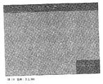
図3Aは、Fe80C15Si5球の2相スピノーダル微細構造のSEMである。Fe80C15Si5を、球内の種々の位置において解析した。図3Aの顕微鏡写真は、相互連結した微細構造を有する、2相スピノーダル構造を示す。両方の相が結晶構造であり、約300nmの平均波長を有する。微細構造のランダムさは、これが結晶化が開始された部位であることを示す。図3Bは、図3Aの試料の中心の顕微鏡写真である。図3Bは、試料中心近くのスピノーダル構造の配列および、配列の異なる向きを示す。図3Cは、開始部位の反対の端における試料の顕微鏡写真である。図3Cは、開始部位の反対の端における共晶組織の形成を示す。図3Dは、この系の破壊挙動を示し、破壊表面は鱗状または雲状である。図3Dの白い曲線は稜線であり、延性破壊が起こったことを示す。図3Eは、試料の破壊表面を示す、図3Aの試料の別の顕微鏡写真である。金属複合材料中の2つの固体スピノーダルは、Fe3Siおよび、体心立法(BCC)FeまたはFeの固溶体である。前者のスピノーダルは脆性であり、一方後者は延性である。破壊すると、延性スピノーダルは破壊表面に稜線を形成する。いかなる特定の理論にも縛られず、高い強度および高い衝撃破壊エネルギーは、BCCFe(または固溶体Fe)のためであると考えられている。 FIG. 3A is a SEM of a two-phase spinodal microstructure of Fe 80 C 15 Si 5 spheres. Fe 80 C 15 Si 5 was analyzed at various locations within the sphere. The micrograph in FIG. 3A shows a two-phase spinodal structure with interconnected microstructures. Both phases are crystalline structures and have an average wavelength of about 300 nm. The randomness of the microstructure indicates that this is the site where crystallization has started. FIG. 3B is a photomicrograph of the center of the sample of FIG. 3A. FIG. 3B shows an array of spinodal structures near the sample center and different orientations of the array. FIG. 3C is a photomicrograph of the sample at the opposite end of the start site. FIG. 3C shows the formation of a eutectic structure at the opposite end of the start site. FIG. 3D shows the fracture behavior of this system, the fracture surface being scaly or cloudy. The white curve in FIG. 3D is a ridgeline, indicating that ductile fracture has occurred. FIG. 3E is another photomicrograph of the sample of FIG. 3A showing the fracture surface of the sample. The two solid spinodals in the metal composite are Fe 3 Si and body-centered (BCC) Fe or a solid solution of Fe. The former spinodal is brittle, while the latter is ductile. When broken, the ductile spinodal forms a ridge on the fracture surface. Without being bound to any particular theory, it is believed that high strength and high impact fracture energy are due to BCCFe (or solid solution Fe).
非常に大きいΔT、例えば100〜500Kにおいて、溶融物は2つの液体スピノーダルに分離する。これら2つの液体スピノーダルは準安定であり、従って結晶化しやすい傾向にあった。結晶化は溶融試料の表面の1点において開始された(初期結晶化部位と呼ぶ)。次に結晶化の最前部は、溶融試料全体が結晶となるまで広がった。結晶化の間熱が開放され(結晶化熱)、これは初期結晶化部位からの距離が増加した位置での、微細構造における変化の部分的な原因となり得た。初期結晶化部位において結晶の成長は速く、開放される熱は比較的小さいため、液体スピノーダルの形態は固体スピノーダルの形態に類似する場合もあった。初期結晶化部位から離れるにつれて、スピノーダル形態は進化した。 At very large ΔT, eg 100-500K, the melt separates into two liquid spinodals. These two liquid spinodals were metastable and therefore tended to crystallize easily. Crystallization was initiated at one point on the surface of the molten sample (referred to as the initial crystallization site). Next, the forefront of crystallization spread until the entire molten sample became crystalline. Heat was released during crystallization (crystallization heat), which could be partly responsible for changes in the microstructure at locations where the distance from the initial crystallization site increased. Because the crystal growth is fast at the initial crystallization site and the heat released is relatively small, the liquid spinodal form may be similar to the solid spinodal form. The spinodal morphology evolved away from the initial crystallization site.
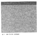
比較すると、図2は、典型的にはオーステナイトとマルテンサイトの混合物であり、従来方法により作製した従来の鋼球の微細構造のSEMである。一般に、コイル線(オーステナイト、柔らかい)形態の鋼を製造する。短い円筒形の片を線から切り取り、ヘッディングマシン(heading machine)で冷間鍛造する。ヘッディングした球の表面は、フラッシングマシン(flashing machine)で研磨する。球を次に炉内で硬化し、オーステナイトの半分以上を硬いマルテンサイトに変換する。硬化後、球はさらに2回研磨過程を通って(研磨およびラッピング)所望の表面仕上げが施される。次に球を洗浄し、ポリッシュする。鋼球を調製する従来方法の欠点は、高品質のコイル線を用いる必要性および、熱処理が全てのオーステナイトをマルテンサイトに変換しないことを保証する必要性である。さらに、全てのオーステナイトが変換されないため、従来の鋼球は、例えば150℃より高い、高温での用途に好適でない可能性がある。 In comparison, FIG. 2 is a SEM of a conventional steel ball microstructure, typically a mixture of austenite and martensite, prepared by conventional methods. Generally, steel in the form of coil wire (austenite, soft) is produced. A short cylindrical piece is cut from the wire and cold forged with a heading machine. The surface of the headed sphere is polished with a flashing machine. The spheres are then cured in an oven to convert more than half of the austenite to hard martensite. After curing, the sphere is passed through the polishing process twice (polishing and lapping) to give the desired surface finish. The spheres are then washed and polished. The disadvantages of conventional methods of preparing steel balls are the need to use high quality coil wires and the need to ensure that the heat treatment does not convert all austenite to martensite. Furthermore, since all austenite is not converted, conventional steel balls may not be suitable for high temperature applications, for example, higher than 150 ° C.
いかなる特定の理論にも縛られず、本発明の延性相を含む微細構造は、従来方法で作製した類似のものと比較した場合、独自の物理特性を有するミクロ構造またはナノ構造の物体を提供し、その特性の例としては:高い圧縮破壊強度、高いヤング率、高い疲労耐性、および高い熱安定性であり、一方で、同様の耐磨耗性および硬度を維持しつつ、セラミック球と同様の衝撃破壊エネルギーを示す。 Without being bound to any particular theory, the microstructure comprising the ductile phase of the present invention provides a microstructured or nanostructured object with unique physical properties when compared to similar ones made by conventional methods; Examples of its properties are: high compressive fracture strength, high Young's modulus, high fatigue resistance, and high thermal stability, while maintaining the same wear resistance and hardness while having the same impact as a ceramic sphere Indicates destruction energy.
例II.
Fe:40.5原子%
CO:40.5原子%
C:14原子%
Si:5原子%
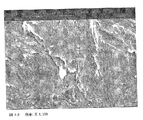
結晶化温度は約800℃であった。形成されたFe40.5CO40.5C14Si5インゴット(試料)の微細構造を、図4A〜4Dに示す。図4Aは、最初に結晶化した、試料の自由表面に位置する試料部分の微細構造を示す。図4Aには異なる相の2つの固体スピノーダルがあり、これらは一緒になってランダムネットワークを形成している。図4Bは、試料の反対側の端において最後に結晶化した試料部分の微細構造を示す。図4Bに示すように、この微細構造はスピノーダル形態と共晶構造の混合である。図4Cは、試料の破壊表面を示し、明るい稜線は2つのスピノーダルの1つで延性破壊が起こったことを示す。稜線の分布は、スピノーダル機構の予想と整合する。共晶が主である領域においては、図4Dにおいて破壊表面上に共晶形態が示される。
Example II.
Fe: 40.5 atomic%
CO: 40.5 atomic%
C: 14 atomic%
Si: 5 atomic%
The crystallization temperature was about 800 ° C. The microstructure of the formed Fe 40.5 CO 40.5 C 14 Si 5 ingot (sample) is shown in FIGS. FIG. 4A shows the microstructure of the sample portion that is first crystallized and located on the free surface of the sample. In FIG. 4A there are two solid spinodals of different phases, which together form a random network. FIG. 4B shows the microstructure of the last sample portion crystallized at the opposite end of the sample. As shown in FIG. 4B, this microstructure is a mixture of spinodal and eutectic structures. FIG. 4C shows the fracture surface of the sample and the bright ridge indicates that ductile fracture occurred in one of the two spinodals. The ridge distribution is consistent with the expectation of the spinodal mechanism. In regions where the eutectic is predominant, the eutectic morphology is shown on the fracture surface in FIG. 4D.
例III.
CO:75原子%
Si:15原子%
B:10原子%
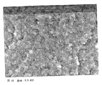
結晶化は約800℃で起こった。形成されたCO75Si15B10インゴット(試料)の微細構造を図5A〜5Dに示す。図5Aは、最初に結晶化した、インゴットの自由表面に位置する試料部分の微細構造を示す。図5Aには異なる相の2つの固体スピノーダルがあり、ネットワークを形成している。ネットワーク形態は、試料中でその位置が結晶化が開始された部位から遠くなるにつれて変化する。試料の中心に近づくと、図5Bに示すように、1つの固体スピノーダルがはっきりと長細い粒状に分解している。長細い粒子は約20ミクロンを超えることができる。複数相の層が長細い粒子を分離している。図5Cは、最初の結晶化の部位から遠い位置における微細構造を示す。図5Cに示すように、最後に結晶化した試料部分の長細い粒子を囲む層は、実質的に均一に見える。図5Dは試料の破壊表面であり、長細い粒子を囲む層が延性であることを示す。いかなる特定の理論にも縛られず、延性層は、衝撃破壊エネルギーおよび強度を有する試料を提供すると考えられる。
Example III.
CO: 75 atomic%
Si: 15 atomic%
B: 10 atomic%
Crystallization occurred at about 800 ° C. The microstructure of the formed CO 75 Si 15 B 10 ingot (sample) is shown in FIGS. FIG. 5A shows the microstructure of the sample portion that was first crystallized and located on the free surface of the ingot. In FIG. 5A, there are two solid spinodals of different phases, forming a network. The network morphology changes as the position in the sample becomes farther from the site where crystallization is initiated. When approaching the center of the sample, one solid spinodal is clearly broken into long and thin granules as shown in FIG. 5B. Long thin particles can exceed about 20 microns. A multi-phase layer separates long thin particles. FIG. 5C shows the microstructure at a location far from the initial crystallization site. As shown in FIG. 5C, the layer surrounding the elongated particles of the last crystallized sample portion appears to be substantially uniform. FIG. 5D is the fracture surface of the sample, showing that the layer surrounding the long thin particles is ductile. Without being bound to any particular theory, it is believed that the ductile layer provides a sample with impact fracture energy and strength.
例IV.
Fe:82原子%
C:18原子%
結晶化温度は約650℃であった。調製されたFe82C18のインゴットの微細構造を図6Aに示す。図6Aには多くのドメインがあり、それらの各々は整列したネットワーク様構造により占領されている。ドメインの間の境界は比較的平らであり、境界近くのネットワークの配列は鮮明である。明らかに、ネットワーク分枝の再配列の形状が、境界を形成する結晶化の間に生じていた。図6Bは、図6Aの試料の破壊表面の微細構造を示す。図6Aに示すように、顕微鏡写真の中心近くに2本の垂直な線が見出され、上記の境界を表わしている。これらの境界に付着しているのは、樹枝状結晶のものに似た整列した特徴である。境界からさらに遠ざかると、鱗状または雲状の構造が微細構造を再び支配している。図6Bの明るい部分は、延性破壊した稜線を示す。
本発明の少なくとも1つの態様の幾つかの側面をこのように記載したので、当業者は容易に、種々の改変、修飾および改善を思い付くであろうことが理解される。かかる改変、修飾および改善は本開示の一部とすることを意図し、本発明の精神および範囲内であることを意図する。従って、前記の説明および図面は、例示目的のみを意図する。
Example IV.
Fe: 82 atomic%
C: 18 atomic%
The crystallization temperature was about 650 ° C. The microstructure of the prepared Fe 82 C 18 ingot is shown in FIG. 6A. There are many domains in FIG. 6A, each of which is occupied by an aligned network-like structure. The boundaries between the domains are relatively flat and the network arrangement near the boundaries is clear. Apparently, the shape of the rearrangement of network branches occurred during the crystallization forming the boundary. FIG. 6B shows the microstructure of the fracture surface of the sample of FIG. 6A. As shown in FIG. 6A, two vertical lines are found near the center of the micrograph, representing the boundary described above. Adhering to these boundaries are aligned features similar to those of dendrites. Further away from the boundary, scale-like or cloud-like structures dominate the microstructure again. The bright part of FIG. 6B shows a ridge line that has been ductile fractured.
Having thus described several aspects of at least one embodiment of the present invention, it is understood that various alterations, modifications, and improvements will readily occur to those skilled in the art. Such alterations, modifications, and improvements are intended to be part of this disclosure, and are intended to be within the spirit and scope of the invention. Accordingly, the foregoing description and drawings are intended for illustrative purposes only.
Claims (69)
該合金を精製すること;および
少なくとも1つの延性サブネットワーク構造を含む、該合金のネットワーク構造を形成すること
を含む、方法。 Forming an alloy;
Refining the alloy; and forming a network structure of the alloy comprising at least one ductile subnetwork structure.
合金を加熱して、溶融合金を形成すること;および
該溶融合金をフラックス材料と接触させること
を含む、請求項4に記載の方法。 Refining the alloy
5. The method of claim 4, comprising heating the alloy to form a molten alloy; and contacting the molten alloy with a flux material.
容器の第1の部分を真空下で加熱し、合金を溶融して容器の第2の部分中に流入させること;および
容器の第2の部分を冷却すること
をさらに含む、請求項1に記載の方法。 Placing the alloy in the first part of the container;
2. The method of claim 1, further comprising heating the first portion of the container under vacuum to melt the alloy and flow into the second portion of the container; and cooling the second portion of the container. the method of.
合金を形成すること;
該合金を精製すること;
1または2以上のスピノーダルを形成すること;および
前記1または2以上のスピノーダルを加熱して、1または2以上の脆性スピノーダルの少なくとも1つを1または2以上の延性相に変換すること、
を含む、前記方法。 A method of forming a metal composite material, comprising:
Forming an alloy;
Purifying the alloy;
Forming one or more spinodals; and heating the one or more spinodals to convert at least one of the one or more brittle spinodals into one or more ductile phases;
Said method.
Applications Claiming Priority (2)
| Application Number | Priority Date | Filing Date | Title |
|---|---|---|---|
| US11/088,106 US20060213586A1 (en) | 2005-03-23 | 2005-03-23 | Metal composites and methods for forming same |
| PCT/CN2006/000483 WO2006099808A1 (en) | 2005-03-23 | 2006-03-23 | Metal composites and methods for forming same |
Publications (2)
| Publication Number | Publication Date |
|---|---|
| JP2008537763A true JP2008537763A (en) | 2008-09-25 |
| JP2008537763A5 JP2008537763A5 (en) | 2009-07-16 |
Family
ID=37023374
Family Applications (1)
| Application Number | Title | Priority Date | Filing Date |
|---|---|---|---|
| JP2008502227A Pending JP2008537763A (en) | 2005-03-23 | 2006-03-23 | Metal composite material and method of forming the same |
Country Status (6)
| Country | Link |
|---|---|
| US (2) | US20060213586A1 (en) |
| EP (1) | EP1861515A4 (en) |
| JP (1) | JP2008537763A (en) |
| CN (1) | CN101203622A (en) |
| TW (1) | TW200641151A (en) |
| WO (1) | WO2006099808A1 (en) |
Cited By (2)
| Publication number | Priority date | Publication date | Assignee | Title |
|---|---|---|---|---|
| KR20110111499A (en) * | 2009-02-03 | 2011-10-11 | 더 나노스틸 컴퍼니, 인코포레이티드 | Method and product for cutting materials |
| JP2014504328A (en) * | 2010-11-02 | 2014-02-20 | ザ・ナノスティール・カンパニー・インコーポレーテッド | Glassy nanomaterial |
Families Citing this family (19)
| Publication number | Priority date | Publication date | Assignee | Title |
|---|---|---|---|---|
| EP2361320B1 (en) * | 2008-10-21 | 2017-09-13 | The Nanosteel Company, Inc. | Mechanism of structural formation for metallic glass based composites exhibiting ductility |
| US8807197B2 (en) * | 2010-02-02 | 2014-08-19 | The Nanosteel Company, Inc. | Utilization of carbon dioxide and/or carbon monoxide gases in processing metallic glass compositions |
| CN103917673B (en) | 2011-08-22 | 2016-04-13 | 加利福尼亚技术学院 | The block nickel based metal glass containing chromium and phosphorus |
| WO2014012113A2 (en) * | 2012-07-13 | 2014-01-16 | The Nanosteel Company, Inc. | Glassy metal fiber laminate |
| US11377720B2 (en) | 2012-09-17 | 2022-07-05 | Glassimetal Technology Inc. | Bulk nickel-silicon-boron glasses bearing chromium |
| KR101997183B1 (en) | 2012-10-30 | 2019-07-08 | 글라시메탈 테크놀로지, 인크. | Bulk nickel-based chromium and phosphorus bearing metallic glasses with high toughness |
| WO2014078697A2 (en) | 2012-11-15 | 2014-05-22 | Glassimetal Technology, Inc. | Bulk nickel-phosphorus-boron glasses bearing chromium and tantalum |
| US9534283B2 (en) * | 2013-01-07 | 2017-01-03 | Glassimental Technology, Inc. | Bulk nickel—silicon—boron glasses bearing iron |
| JP6301681B2 (en) | 2013-02-26 | 2018-03-28 | グラッシメタル テクノロジー インコーポレイテッド | Bulk nickel-phosphorus-boron glass containing manganese |
| US9863025B2 (en) | 2013-08-16 | 2018-01-09 | Glassimetal Technology, Inc. | Bulk nickel-phosphorus-boron glasses bearing manganese, niobium and tantalum |
| US9920400B2 (en) | 2013-12-09 | 2018-03-20 | Glassimetal Technology, Inc. | Bulk nickel-based glasses bearing chromium, niobium, phosphorus and silicon |
| US9957596B2 (en) | 2013-12-23 | 2018-05-01 | Glassimetal Technology, Inc. | Bulk nickel-iron-based, nickel-cobalt-based and nickel-copper based glasses bearing chromium, niobium, phosphorus and boron |
| US10000834B2 (en) | 2014-02-25 | 2018-06-19 | Glassimetal Technology, Inc. | Bulk nickel-chromium-phosphorus glasses bearing niobium and boron exhibiting high strength and/or high thermal stability of the supercooled liquid |
| US10287663B2 (en) | 2014-08-12 | 2019-05-14 | Glassimetal Technology, Inc. | Bulk nickel-phosphorus-silicon glasses bearing manganese |
| US10246335B2 (en) * | 2016-05-27 | 2019-04-02 | Baker Hughes, A Ge Company, Llc | Methods of modifying surfaces of diamond particles, and related diamond particles and earth-boring tools |
| US11905582B2 (en) | 2017-03-09 | 2024-02-20 | Glassimetal Technology, Inc. | Bulk nickel-niobium-phosphorus-boron glasses bearing low fractions of chromium and exhibiting high toughness |
| US10458008B2 (en) | 2017-04-27 | 2019-10-29 | Glassimetal Technology, Inc. | Zirconium-cobalt-nickel-aluminum glasses with high glass forming ability and high reflectivity |
| US11371108B2 (en) | 2019-02-14 | 2022-06-28 | Glassimetal Technology, Inc. | Tough iron-based glasses with high glass forming ability and high thermal stability |
| CN113265556B (en) * | 2021-05-18 | 2022-04-26 | 西北工业大学 | Method for improving microstructure uniformity and frictional wear performance of Cu-containing multi-principal-element alloy |
Citations (2)
| Publication number | Priority date | Publication date | Assignee | Title |
|---|---|---|---|---|
| JPH1112672A (en) * | 1997-04-30 | 1999-01-19 | Sumitomo Electric Ind Ltd | Aluminum alloy with high toughness and high heat resistance, and its manufacture |
| JP2004339532A (en) * | 2003-05-13 | 2004-12-02 | Hitachi Metals Ltd | Method of producing tool steel |
Family Cites Families (4)
| Publication number | Priority date | Publication date | Assignee | Title |
|---|---|---|---|---|
| WO1981000861A1 (en) * | 1979-09-21 | 1981-04-02 | Hitachi Metals Ltd | Amorphous alloys |
| US4406712A (en) * | 1980-03-24 | 1983-09-27 | Bell Telephone Laboratories, Incorporated | Cu-Ni-Sn Alloy processing |
| US6716292B2 (en) * | 1995-06-07 | 2004-04-06 | Castech, Inc. | Unwrought continuous cast copper-nickel-tin spinodal alloy |
| AU712068B2 (en) * | 1995-06-07 | 1999-10-28 | Castech, Inc. | Unwrought continuous cast copper-nickel-tin spinodal alloy |
-
2005
- 2005-03-23 US US11/088,106 patent/US20060213586A1/en not_active Abandoned
-
2006
- 2006-03-23 CN CN200680017144.1A patent/CN101203622A/en active Pending
- 2006-03-23 JP JP2008502227A patent/JP2008537763A/en active Pending
- 2006-03-23 EP EP06722135A patent/EP1861515A4/en not_active Withdrawn
- 2006-03-23 WO PCT/CN2006/000483 patent/WO2006099808A1/en active Application Filing
- 2006-03-23 TW TW095110087A patent/TW200641151A/en unknown
-
2012
- 2012-05-16 US US13/472,801 patent/US20130098510A1/en not_active Abandoned
Patent Citations (2)
| Publication number | Priority date | Publication date | Assignee | Title |
|---|---|---|---|---|
| JPH1112672A (en) * | 1997-04-30 | 1999-01-19 | Sumitomo Electric Ind Ltd | Aluminum alloy with high toughness and high heat resistance, and its manufacture |
| JP2004339532A (en) * | 2003-05-13 | 2004-12-02 | Hitachi Metals Ltd | Method of producing tool steel |
Non-Patent Citations (3)
| Title |
|---|
| JPN6012025716; W. H. Guo and H.W. Kui: 'Bulk nanostructured alloy formation with controllable grain size' Acta materialia vol. 48, No. 9, 200005, p. 2117 - 2121 * |
| JPN6012025717; J. E. May et al.: 'Amorphous phase partitioning in FeCo-based metallic glass alloys' Journal of non-crystalline solids vol. 348, 200411, p. 250 - 257 * |
| JPN7012001878; C. C. Leung, W. H. Guo and H. W. Kui: 'Formation of amorphous nanostructured materials by liquid state spinodal decomposition' Applied physics letters vol. 77 No. 1, 200007, p. 64 - 66 * |
Cited By (4)
| Publication number | Priority date | Publication date | Assignee | Title |
|---|---|---|---|---|
| KR20110111499A (en) * | 2009-02-03 | 2011-10-11 | 더 나노스틸 컴퍼니, 인코포레이티드 | Method and product for cutting materials |
| KR101642165B1 (en) | 2009-02-03 | 2016-07-22 | 더 나노스틸 컴퍼니, 인코포레이티드 | Method and product for cutting materials |
| JP2014504328A (en) * | 2010-11-02 | 2014-02-20 | ザ・ナノスティール・カンパニー・インコーポレーテッド | Glassy nanomaterial |
| JP2017082336A (en) * | 2010-11-02 | 2017-05-18 | ザ・ナノスティール・カンパニー・インコーポレーテッド | Glassy nano-materials |
Also Published As
| Publication number | Publication date |
|---|---|
| US20130098510A1 (en) | 2013-04-25 |
| WO2006099808A1 (en) | 2006-09-28 |
| EP1861515A1 (en) | 2007-12-05 |
| EP1861515A4 (en) | 2009-12-30 |
| TW200641151A (en) | 2006-12-01 |
| CN101203622A (en) | 2008-06-18 |
| US20060213586A1 (en) | 2006-09-28 |
Similar Documents
| Publication | Publication Date | Title |
|---|---|---|
| JP2008537763A (en) | Metal composite material and method of forming the same | |
| US7833361B2 (en) | Alloy and method for producing magnetic refrigeration material particles using same | |
| JP6435359B2 (en) | Mechanism of structure formation of composites based on metallic glass exhibiting ductility | |
| JP4137095B2 (en) | Magnesium-based amorphous alloy with excellent amorphous formability and ductility | |
| JPS6032704B2 (en) | Alloy with ultra-fine homogeneously dispersed crystalline phase | |
| JPH02503331A (en) | Magnesium alloy with high mechanical resistance and manufacturing method by rapid solidification of the alloy | |
| Yang et al. | Effect of minor Cu content on microstructure and mechanical property of NiTiCu bulk alloys fabricated by crystallization of metallic glass powder | |
| WO2003040422A1 (en) | Alloy and method of producing the same | |
| Gang et al. | Shape memory TiNi powders produced by plasma rotating electrode process for additive manufacturing | |
| JP2010144245A (en) | Zr BASED METAL GLASS ALLOY | |
| JPH03267355A (en) | Aluminum-chromium alloy and its production | |
| JP4317930B2 (en) | Amorphous alloy particles | |
| CN110193597B (en) | Method for producing crystalline aluminum-iron-silicon alloy | |
| WO1992007676A1 (en) | Hypereutectic aluminum/silicon alloy powder and production thereof | |
| KR19980081847A (en) | Toughness heat resistant aluminum alloy and method for manufacturing same | |
| Průša et al. | Characterization of the Al-13Si-10Fe alloy produced by centrifugal atomization and ultra-high-pressure compaction | |
| JPH10158755A (en) | Production of bcc type hydrogen storage alloy | |
| Kapinos et al. | The Effect of Rare Earth Addition on Microstructure and Mechanical Properties of the Rapidly Solidified Al-Si And Al-Si-Ni Alloys | |
| JP2004099940A (en) | Method for producing magnesium based alloy | |
| KR101501068B1 (en) | Zr-based amorphous alloy composition | |
| KR102159780B1 (en) | Nanostructured shape memory alloys and manufacturing method thereof | |
| JP2007217722A (en) | Metal ball for rolling motion object having excellent formability | |
| Simchi et al. | Melt Spinning of Amorphous Aluminum Alloys Containing Transition (Ni, Fe, Cu) and Mish Metals: Thermal Stability and Nano-crystallization | |
| CN114606452A (en) | High-plasticity Hf-based two-phase amorphous alloy and preparation method thereof | |
| CN1392281A (en) | Massive non-crystal alloy |
Legal Events
| Date | Code | Title | Description |
|---|---|---|---|
| A521 | Request for written amendment filed |
Free format text: JAPANESE INTERMEDIATE CODE: A523 Effective date: 20090323 |
|
| A621 | Written request for application examination |
Free format text: JAPANESE INTERMEDIATE CODE: A621 Effective date: 20090323 |
|
| A521 | Request for written amendment filed |
Free format text: JAPANESE INTERMEDIATE CODE: A523 Effective date: 20090522 |
|
| A131 | Notification of reasons for refusal |
Free format text: JAPANESE INTERMEDIATE CODE: A131 Effective date: 20120529 |
|
| A02 | Decision of refusal |
Free format text: JAPANESE INTERMEDIATE CODE: A02 Effective date: 20121106 |