JP2008531955A - Centrifugal clutch and actuator - Google Patents
Centrifugal clutch and actuator Download PDFInfo
- Publication number
- JP2008531955A JP2008531955A JP2008500248A JP2008500248A JP2008531955A JP 2008531955 A JP2008531955 A JP 2008531955A JP 2008500248 A JP2008500248 A JP 2008500248A JP 2008500248 A JP2008500248 A JP 2008500248A JP 2008531955 A JP2008531955 A JP 2008531955A
- Authority
- JP
- Japan
- Prior art keywords
- centrifugal clutch
- actuator
- coupling
- centrifugal
- drive
- Prior art date
- Legal status (The legal status is an assumption and is not a legal conclusion. Google has not performed a legal analysis and makes no representation as to the accuracy of the status listed.)
- Pending
Links
Images


Classifications
-
- F—MECHANICAL ENGINEERING; LIGHTING; HEATING; WEAPONS; BLASTING
- F16—ENGINEERING ELEMENTS AND UNITS; GENERAL MEASURES FOR PRODUCING AND MAINTAINING EFFECTIVE FUNCTIONING OF MACHINES OR INSTALLATIONS; THERMAL INSULATION IN GENERAL
- F16D—COUPLINGS FOR TRANSMITTING ROTATION; CLUTCHES; BRAKES
- F16D3/00—Yielding couplings, i.e. with means permitting movement between the connected parts during the drive
- F16D3/50—Yielding couplings, i.e. with means permitting movement between the connected parts during the drive with the coupling parts connected by one or more intermediate members
- F16D3/64—Yielding couplings, i.e. with means permitting movement between the connected parts during the drive with the coupling parts connected by one or more intermediate members comprising elastic elements arranged between substantially-radial walls of both coupling parts
- F16D3/68—Yielding couplings, i.e. with means permitting movement between the connected parts during the drive with the coupling parts connected by one or more intermediate members comprising elastic elements arranged between substantially-radial walls of both coupling parts the elements being made of rubber or similar material
-
- F—MECHANICAL ENGINEERING; LIGHTING; HEATING; WEAPONS; BLASTING
- F16—ENGINEERING ELEMENTS AND UNITS; GENERAL MEASURES FOR PRODUCING AND MAINTAINING EFFECTIVE FUNCTIONING OF MACHINES OR INSTALLATIONS; THERMAL INSULATION IN GENERAL
- F16D—COUPLINGS FOR TRANSMITTING ROTATION; CLUTCHES; BRAKES
- F16D3/00—Yielding couplings, i.e. with means permitting movement between the connected parts during the drive
- F16D3/50—Yielding couplings, i.e. with means permitting movement between the connected parts during the drive with the coupling parts connected by one or more intermediate members
- F16D3/72—Yielding couplings, i.e. with means permitting movement between the connected parts during the drive with the coupling parts connected by one or more intermediate members with axially-spaced attachments to the coupling parts
-
- F—MECHANICAL ENGINEERING; LIGHTING; HEATING; WEAPONS; BLASTING
- F16—ENGINEERING ELEMENTS AND UNITS; GENERAL MEASURES FOR PRODUCING AND MAINTAINING EFFECTIVE FUNCTIONING OF MACHINES OR INSTALLATIONS; THERMAL INSULATION IN GENERAL
- F16D—COUPLINGS FOR TRANSMITTING ROTATION; CLUTCHES; BRAKES
- F16D43/00—Automatic clutches
- F16D43/02—Automatic clutches actuated entirely mechanically
- F16D43/04—Automatic clutches actuated entirely mechanically controlled by angular speed
- F16D43/14—Automatic clutches actuated entirely mechanically controlled by angular speed with centrifugal masses actuating the clutching members directly in a direction which has at least a radial component; with centrifugal masses themselves being the clutching members
- F16D43/16—Automatic clutches actuated entirely mechanically controlled by angular speed with centrifugal masses actuating the clutching members directly in a direction which has at least a radial component; with centrifugal masses themselves being the clutching members with clutching members having interengaging parts
-
- F—MECHANICAL ENGINEERING; LIGHTING; HEATING; WEAPONS; BLASTING
- F16—ENGINEERING ELEMENTS AND UNITS; GENERAL MEASURES FOR PRODUCING AND MAINTAINING EFFECTIVE FUNCTIONING OF MACHINES OR INSTALLATIONS; THERMAL INSULATION IN GENERAL
- F16D—COUPLINGS FOR TRANSMITTING ROTATION; CLUTCHES; BRAKES
- F16D43/00—Automatic clutches
- F16D43/02—Automatic clutches actuated entirely mechanically
- F16D43/20—Automatic clutches actuated entirely mechanically controlled by torque, e.g. overload-release clutches, slip-clutches with means by which torque varies the clutching pressure
- F16D43/21—Automatic clutches actuated entirely mechanically controlled by torque, e.g. overload-release clutches, slip-clutches with means by which torque varies the clutching pressure with friction members
- F16D43/211—Automatic clutches actuated entirely mechanically controlled by torque, e.g. overload-release clutches, slip-clutches with means by which torque varies the clutching pressure with friction members with radially applied torque-limiting friction surfaces
-
- F—MECHANICAL ENGINEERING; LIGHTING; HEATING; WEAPONS; BLASTING
- F16—ENGINEERING ELEMENTS AND UNITS; GENERAL MEASURES FOR PRODUCING AND MAINTAINING EFFECTIVE FUNCTIONING OF MACHINES OR INSTALLATIONS; THERMAL INSULATION IN GENERAL
- F16D—COUPLINGS FOR TRANSMITTING ROTATION; CLUTCHES; BRAKES
- F16D47/00—Systems of clutches, or clutches and couplings, comprising devices of types grouped under at least two of the preceding guide headings
-
- F—MECHANICAL ENGINEERING; LIGHTING; HEATING; WEAPONS; BLASTING
- F16—ENGINEERING ELEMENTS AND UNITS; GENERAL MEASURES FOR PRODUCING AND MAINTAINING EFFECTIVE FUNCTIONING OF MACHINES OR INSTALLATIONS; THERMAL INSULATION IN GENERAL
- F16H—GEARING
- F16H55/00—Elements with teeth or friction surfaces for conveying motion; Worms, pulleys or sheaves for gearing mechanisms
- F16H55/02—Toothed members; Worms
- F16H55/14—Construction providing resilience or vibration-damping
-
- E—FIXED CONSTRUCTIONS
- E05—LOCKS; KEYS; WINDOW OR DOOR FITTINGS; SAFES
- E05F—DEVICES FOR MOVING WINGS INTO OPEN OR CLOSED POSITION; CHECKS FOR WINGS; WING FITTINGS NOT OTHERWISE PROVIDED FOR, CONCERNED WITH THE FUNCTIONING OF THE WING
- E05F15/00—Power-operated mechanisms for wings
- E05F15/60—Power-operated mechanisms for wings using electrical actuators
- E05F15/603—Power-operated mechanisms for wings using electrical actuators using rotary electromotors
- E05F15/665—Power-operated mechanisms for wings using electrical actuators using rotary electromotors for vertically-sliding wings
- E05F15/689—Power-operated mechanisms for wings using electrical actuators using rotary electromotors for vertically-sliding wings specially adapted for vehicle windows
- E05F15/697—Motor units therefor, e.g. geared motors
-
- F—MECHANICAL ENGINEERING; LIGHTING; HEATING; WEAPONS; BLASTING
- F02—COMBUSTION ENGINES; HOT-GAS OR COMBUSTION-PRODUCT ENGINE PLANTS
- F02N—STARTING OF COMBUSTION ENGINES; STARTING AIDS FOR SUCH ENGINES, NOT OTHERWISE PROVIDED FOR
- F02N15/00—Other power-operated starting apparatus; Component parts, details, or accessories, not provided for in, or of interest apart from groups F02N5/00 - F02N13/00
- F02N15/02—Gearing between starting-engines and started engines; Engagement or disengagement thereof
- F02N15/022—Gearing between starting-engines and started engines; Engagement or disengagement thereof the starter comprising an intermediate clutch
- F02N15/026—Gearing between starting-engines and started engines; Engagement or disengagement thereof the starter comprising an intermediate clutch of the centrifugal type
-
- F—MECHANICAL ENGINEERING; LIGHTING; HEATING; WEAPONS; BLASTING
- F16—ENGINEERING ELEMENTS AND UNITS; GENERAL MEASURES FOR PRODUCING AND MAINTAINING EFFECTIVE FUNCTIONING OF MACHINES OR INSTALLATIONS; THERMAL INSULATION IN GENERAL
- F16H—GEARING
- F16H1/00—Toothed gearings for conveying rotary motion
- F16H1/02—Toothed gearings for conveying rotary motion without gears having orbital motion
- F16H1/04—Toothed gearings for conveying rotary motion without gears having orbital motion involving only two intermeshing members
- F16H1/12—Toothed gearings for conveying rotary motion without gears having orbital motion involving only two intermeshing members with non-parallel axes
- F16H1/16—Toothed gearings for conveying rotary motion without gears having orbital motion involving only two intermeshing members with non-parallel axes comprising worm and worm-wheel
Abstract
アクチュエータの大きさと重さを相当に減らす。所定のしきい値より上の回転スピードにおいて駆動軸を被駆動部材に結合する遠心クラッチであって、一端に塊状の拡大体(320)と、第1の結合用形成体とを有する遠心スライダー(302)と、前記遠心スライダーを支持するフレームであって、前記遠心スライダーが拡大された直径の位置と縮小された直径の位置との間で滑動するように抑制し、前記遠心スライダーによって駆動される前記滑動の軸と直角な前記駆動軸に固定的に取り付けられるよう形成体に形成されたフレームと、前記駆動軸にフライホイール(3)を形成するように、前記遠心スライダーがその拡大された直径の位置にあるときにのみ前記遠心スライダーの慣性中心が同軸になるように前記フレーム(301)と前記スライダー(302)が協働して、前記クラッチが係合したときにその回転が完全に釣り合いが取れる、フレームを有する遠心クラッチ。Significantly reduce the size and weight of the actuator. A centrifugal clutch that couples a drive shaft to a driven member at a rotational speed above a predetermined threshold value, and has a massive expansion body (320) at one end and a first coupling formation body ( 302) and a frame for supporting the centrifugal slider, wherein the centrifugal slider is controlled to slide between an enlarged diameter position and a reduced diameter position, and is driven by the centrifugal slider. The frame formed on the forming body to be fixedly attached to the drive shaft perpendicular to the sliding axis, and the enlarged diameter of the centrifugal slider so as to form a flywheel (3) on the drive shaft. The frame (301) and the slider (302) cooperate so that the center of inertia of the centrifugal slider is coaxial only when the Ji is the rotation balance can be taken completely when engaged, the centrifugal clutch having a frame.
Description
本発明は、遠心クラッチ、すなわち、オーバー・ランニング・クラッチ、及び、遠心クラッチを含んだアクチュエータに関する。本発明はまた、静摩擦抗力(drag)及び動摩擦抗力の影響を受ける負荷を動かす駆動システム、負荷を駆動する方法に関する。本発明は特に、排他的ではないが、自動車の座席、サンルーフ、窓、ハンドルロック、フロントガラスワイパー、自動マニュアル変速機、座席調整装置、電動駐車ブレーキ、シートベルトプリテンショナー(pretensioners)、エンジン始動モータ、ブレーキ装置、自動ギヤボックス、要するに、慣性質量を動かし、それを制御された動きに保つように設計された任意の駆動機構の駆動に用いて有益である。原理的には、本発明は負荷が摩擦抵抗に抗して動かされるあらゆる回転的または直線的な駆動システムに適用可能であり、本発明は特に静摩擦に打ち勝つのに有用である。本発明は、エレベータや販売用コンベヤーの小売ポイントなどの種々の分野における用途を見出している。 The present invention relates to an actuator including a centrifugal clutch, that is, an overrunning clutch, and a centrifugal clutch. The present invention also relates to a drive system for moving a load affected by static friction drag and dynamic friction drag, and a method for driving the load. The present invention is not particularly exclusive, but includes automobile seats, sunroofs, windows, handle locks, windshield wipers, automatic manual transmissions, seat adjusters, electric parking brakes, seat belt pretensioners, engine starter motors Useful for driving brake devices, automatic gearboxes, in short, any drive mechanism designed to move the inertial mass and keep it in controlled motion. In principle, the present invention is applicable to any rotational or linear drive system in which the load is moved against frictional resistance, and the present invention is particularly useful for overcoming static friction. The present invention finds application in various fields, such as retail points for elevators and conveyors for sale.
車両座席、サンルーフ、窓、ステアリング・コラム・ロック、窓面ワイパー、自動化されたマニュアル変速機(半自動変速機)、座席調整装置、電動駐車ブレーキ、シートベルトプリテンショナー、始動モータといったような、自動車内における多くの機能は今や、電気的に動作される。これらの機能の多くは、大きな駆動力またはトルクを必要とし、技術者は一般的に必要な出力を供給するため高出力電気モータを開発してきている。この取り組みの不利な点は、そのような電気モータは大きく、重く、高価であり、カーバッテリーやオルタネータから大電力の入力が要求されることである。 Vehicle interiors such as vehicle seats, sunroofs, windows, steering column locks, window wipers, automated manual transmissions (semi-automatic transmissions), seat adjusters, electric parking brakes, seat belt pretensioners, starter motors, etc. Many functions in are now electrically operated. Many of these functions require large driving forces or torques, and engineers have typically developed high power electric motors to provide the required output. The disadvantage of this approach is that such electric motors are large, heavy and expensive and require high power input from car batteries and alternators.
したがって、本発明の目的は、現在利用可能なアクチュエータのこれらの不利な点を克服し、または軽減することにある。車両の重量、電力消費、価格を低減することに対する増大する圧力が存在し、それにより、車両の性能、経済性が向上し、環境に与えるダメージを低減させる。 Accordingly, it is an object of the present invention to overcome or mitigate these disadvantages of currently available actuators. There is increasing pressure on reducing vehicle weight, power consumption, and price, thereby improving vehicle performance and economy and reducing environmental damage.
したがって、本発明は、所定のしきい値より上の回転スピードにおいて駆動軸が被駆動部材と結合する遠心クラッチを提供し、前記遠心クラッチは、一端に塊状の拡大体(massive enlargement)と、第1の結合用形成体と、を有する遠心スライダーと、前記遠心スライダーを支持する形態で形成されたフレームであって、前記遠心スライダーが拡大された直径の位置と縮小された直径の位置との間で滑動することを抑制し、当該フレームの滑動の軸と直角な軸によって、前記遠心スライダーによって駆動されるべき前記駆動軸に固定的にフィットするよう形成体(formation)に形成されたフレームと、前記駆動軸上で自由に回転するように装着可能で、使用時において前記駆動部材との係合を駆動するように形成され、そして前記遠心スライダーが拡大位置にあるときにのみ前記第1の結合用形成体と駆動的に接続する第2の結合用形成体によって形成された出力駆動部材と、前記遠心スライダーをその縮小位置の方へ偏らせる手段(means for biasing)と、を有し、それにより、前記遠心スライダーと前記フレームの回転によって前記塊状の拡大体が前記スライダーをその前記縮小された直径の位置から前記拡大された直径の位置に直径方向に引き寄せることにより前記第1の結合用形成体と前記第2の結合用形成体とを相互に係合させることで回転運動を前記駆動軸から前記出力結合ギヤへ伝達させ、前記回転が停止したときには前記偏らせる手段が非係合とすることで前記駆動軸を前記出力結合ギヤから非結合とする、遠心クラッチにおいて、前記フレームと前記スライダーは前記駆動シャフト軸上でフライホイールを構成するために協働し、前記遠心スライダーがその拡大された直径の位置にあるときにのみ、前記遠心クラッチの慣性中心が同軸上にあって、その回転は前記クラッチが係合したときに完全に釣り合いが取れることを特徴とする。 Accordingly, the present invention provides a centrifugal clutch in which a drive shaft is coupled to a driven member at a rotational speed above a predetermined threshold, the centrifugal clutch having a massive enlargement at one end, A coupling slider, and a frame formed to support the centrifugal slider, wherein the centrifugal slider is between an enlarged diameter position and a reduced diameter position. A frame formed in a formation to prevent sliding on the frame and to fit securely to the drive shaft to be driven by the centrifugal slider by an axis perpendicular to the axis of sliding of the frame; Mountable to freely rotate on the drive shaft, configured to drive engagement with the drive member in use, and the centrifugal slider expands An output drive member formed by a second coupling formation that is drivingly connected to the first coupling formation only when in the large position, and means for biasing the centrifugal slider toward its reduced position (Means for biasing), whereby the mass expansion body causes the slider to move from the reduced diameter position to the enlarged diameter position by rotating the centrifugal slider and the frame. By pulling in the direction, the first coupling forming body and the second coupling forming body are engaged with each other to transmit rotational motion from the drive shaft to the output coupling gear, and the rotation is stopped. In the centrifugal clutch, the biasing means is disengaged to disengage the drive shaft from the output coupling gear. Only when the centrifugal slider is in its enlarged diameter position, the center of inertia of the centrifugal clutch is coaxial and its rotation is the same as that of the clutch. It is characterized in that it is perfectly balanced when engaged.
この遠心クラッチは、「プリアセンブルされた遠心クラッチ」という命名した私の英国特許出願GB−A−23929583号に開示された特徴を組み込むことができる。フライホイールの慣性モーメント、遠心クラッチが係合する時における予め決められた回転スピード、動力、モータの加速と最高スピードは、あらゆる与えられた用途に適合する遠心クラッチの設計において、静摩擦抵抗と動摩擦抵抗の要求、特定の揚重、または他の負荷の要求が満たされるように、全て選択できる。たとえば、自動車の窓アクチュエータへの遠心クラッチの用途において、当該遠心クラッチが係合するときのスピードと共に、電気モータの定格、および減速ギヤ比が、係合によりアクチュエータに十分な「打撃(kick)」を与えるように設計され、それにより、窓枠の静摩擦に打ち勝ち、通常の使用時において、窓のための連続した上昇を提供し、窓が上昇されているとき動摩擦に打ち克つ。 This centrifugal clutch can incorporate the features disclosed in my UK patent application GB-A-23929583, named “Preassembled Centrifugal Clutch”. The moment of inertia of the flywheel, the predetermined rotational speed when the centrifugal clutch is engaged, the power, the acceleration and maximum speed of the motor are the static and dynamic friction resistances in the design of the centrifugal clutch that suits any given application. Can be selected in such a way that the demands, specific lifting or other load demands are fulfilled. For example, in the application of a centrifugal clutch to an automotive window actuator, the speed at which the centrifugal clutch is engaged, as well as the rating of the electric motor, and the reduction gear ratio are sufficient “kick” for the actuator to engage. In order to overcome the static friction of the window frame, provide a continuous rise for the window during normal use, and overcome dynamic friction when the window is raised.
さらに本発明は、所定のしきい値よりも上の回転スピードで駆動軸を被駆動部材(従動部材、driven member)に結合する遠心クラッチであって、フレームと、前記駆動軸にフライホイールを構成するために協働する遠心スライダーと、使用時に被駆動部材を駆動する結合部材を具備し、前記フライホイールが回転的に結合されて、前記結合部材を駆動して、制限された相対的な回転運動がそれらの間で許容される、遠心クラッチを提供する。 Further, the present invention is a centrifugal clutch that couples a drive shaft to a driven member (driven member) at a rotational speed above a predetermined threshold, and comprises a frame and a flywheel on the drive shaft A centrifugal slider that cooperates to drive and a coupling member that drives the driven member when in use, and the flywheel is rotationally coupled to drive the coupling member for limited relative rotation A centrifugal clutch is provided in which movement is allowed between them.
本発明はまた、遠心クラッチによって出力結合用歯車と駆動的に結合される電気モータを有するアクチュエータであって、前記遠心クラッチは遠心的に結合された駆動部材及び被駆動部材を有し、さらにアクチュエーターは、前記電気モータと前記遠心クラッチの前記被駆動部材との間を駆動的に結合するフライホイールを有し、前記遠心クラッチが前記電気モータと前記出力結合ギヤとを係合させるスピードまで加速する過程で回転慣性を蓄積する、アクチュエータを提供する。 The present invention is also an actuator having an electric motor drivingly coupled to an output coupling gear by a centrifugal clutch, wherein the centrifugal clutch has a driving member and a driven member coupled centrifugally, and further includes an actuator. Has a flywheel for drivingly coupling between the electric motor and the driven member of the centrifugal clutch, and the centrifugal clutch accelerates to a speed at which the electric motor and the output coupling gear are engaged with each other. An actuator is provided that accumulates rotational inertia in the process.
前記フライホイールは、前記遠心クラッチの入力部材と一体になっていてもよい。前記遠心クラッチは、上記の本発明の第1の定義に従うことができ、前記フライホイールを構成する前記フレームと前記スライダーであってよい。 The flywheel may be integrated with an input member of the centrifugal clutch. The centrifugal clutch may follow the first definition of the present invention described above, and may be the frame and the slider constituting the flywheel.
本発明のいくつかの用途のため、出力駆動部材は、使用中に前記被駆動部材の係合を駆動する結合用部材を有し、第2の結合用形成体(coupling formation)は結合用部材を駆動するために回転的に結合され、制限された相対的な回転運動がそれらの間で許容される。 For some applications of the present invention, the output drive member includes a coupling member that drives engagement of the driven member during use, and the second coupling formation is a coupling member. Are rotationally coupled to drive a limited relative rotational motion between them.
過度のトルクがあった場合に、すべりを提供するために、前記結合部材は前記第2の結合用形成体と摩擦的係合によって結合されることができ、それにより、所定の印加されたトルクより上で回転駆動結合体はすべる。 In order to provide a slip in the event of excessive torque, the coupling member can be coupled with the second coupling formation by frictional engagement, whereby a predetermined applied torque. Above that the rotational drive combination slides.
摩擦的な結合の代わりに、前記結合部材は第2の結合用形成体と弾性的に結合していてもよく、それにより、印加されたトルクは、印加されたトルクが減少したときにばね作用によって解放される相対的な回転運動を生じさせる。そこで好ましくは、出力駆動部材は、結合用部材を第2の結合用形成体と駆動的に接続しているねじりばね(torsion spring)を有する。 Instead of a frictional coupling, the coupling member may be elastically coupled to the second coupling formation, so that the applied torque is spring acting when the applied torque is reduced. Produces a relative rotational movement released by. Therefore, preferably, the output drive member has a torsion spring that drivingly connects the coupling member to the second coupling formation.
この弾性結合は、クラッチの係合に直に続くポテンシャルエネルギーを蓄積し、負荷に対する慣性の衝撃的移送(impulsive transfer)をある時間にわたって分散する。このことは、特に静摩擦特性と動摩擦特性を有し得る負荷の要求に適合するように調整され得る。例えば、始動モータはその初期加速の期間、低速度において摩擦が大きい負荷として車両のエンジンを駆動しなければならない。 This elastic coupling accumulates potential energy immediately following clutch engagement and disperses the impulsive transfer of inertia to the load over a period of time. This can be tailored to meet the load requirements, which can in particular have static and dynamic friction characteristics. For example, the starter motor must drive the vehicle engine as a high friction load at low speeds during its initial acceleration.
キック駆動機構(kick-drive mechanism)のパラメータに依存して、衝撃の時点において解放される衝撃トルク(impact torque)は、被駆動(従動)装置の慣性質量を安全に移動させるのに必要な力よりもかなり大きくなる可能性がある。そのような装置の例は、エンジン始動モータ内のキック駆動機構への使用にある。クラッチ機構は、エンジンと連動する(associated)駆動構成要素およびエンジンのフライホイールの慣性質量を加速させることが期待されている。中間的なエネルギー蓄積装置を構成する弾性結合は、クラッチと負荷との間のインターフェース構成要素の破壊を回避するために本質的である。負荷の初期加速の期間、電気モータによって維持が可能な連続的なエネルギーを供給するために、蓄積された回転エネルギーが解放される。同様にして、クラッチ内のフライホイールは、動摩擦抵抗の変動を平滑することに役立ち、それ故、モータに必要な電力が減少し、安定した(consistent)レベルの出力エネルギーを生成する。 Depending on the parameters of the kick-drive mechanism, the impact torque released at the time of impact is the force required to safely move the inertial mass of the driven device. Can be much larger than. An example of such a device is in use for a kick drive mechanism in an engine starter motor. The clutch mechanism is expected to accelerate the drive components associated with the engine and the inertial mass of the engine flywheel. The elastic coupling that constitutes the intermediate energy storage device is essential to avoid breaking the interface components between the clutch and the load. During the initial acceleration of the load, the accumulated rotational energy is released to provide continuous energy that can be maintained by the electric motor. Similarly, the flywheel in the clutch helps smooth out the dynamic frictional resistance variation, thus reducing the power required for the motor and producing a consistent level of output energy.
本発明はまた、静摩擦抗力と動摩擦抗力に支配される負荷を動かす駆動システムを提供し、当該駆動システムは、出力ピニオンが負荷を駆動するために結合される上述した形状のアクチュエータと、負荷と一体になったクラッチの係合の衝撃による負荷の静摩擦抗力(drag)に打ち勝つために、通常の使用において、遠心クラッチの係合のスピードにおける回転慣性が十分なフライホイールと、を有する。 The present invention also provides a drive system for moving a load that is subject to static and dynamic friction drag, the drive system comprising an actuator of the above-described shape with which an output pinion is coupled to drive the load, and an integral with the load. A flywheel with sufficient rotational inertia at the speed of engagement of the centrifugal clutch in normal use in order to overcome the static friction drag of the load due to the impact of the clutch engagement.
さらに本発明は、上述した形式のアクチュエータを使用する、静摩擦抗力と動摩擦抗力に支配される負荷を駆動する方法を提供し、当該方法は、静摩擦抗力と動摩擦抗力に支配される負荷を駆動する電気モータを加速し、静摩擦に打ち勝つためにフライホイールの回転慣性が負荷に衝撃的に伝播される所定のスピードにおいて遠心クラッチを係合させるために電気モータとフライホイールを加速するアクチュエータを使用し、負荷の動摩擦駆動に対抗して負荷を加速するために電気モータの駆動を維持する工程を含む。 The present invention further provides a method of driving a load governed by static and dynamic friction drag using an actuator of the type described above, the method driving an electrical load driven by static and dynamic friction drag. Use an electric motor and an actuator to accelerate the flywheel to engage the centrifugal clutch at a given speed at which the rotational inertia of the flywheel is shockedly propagated to the load to accelerate the motor and overcome static friction Maintaining the drive of the electric motor to accelerate the load against the dynamic friction drive.
電気アクチュエータは、両端停止(end stops)間で負荷を動かすのに使用されることができ、アクチュエータが行き止まり(dead end)に達すると、損傷を受ける可能性があり騒々しい可能性があるバックラッシュをアクチュエータが経験する。したがって、発明はさらに、減速歯車装置を介して出力結合歯車と結合する電気モータを有するアクチュエータを提供し、前記減速歯車装置は、対応する駆動歯車と被駆動(従動)歯車とがかみあうそれぞれの歯が付いた2つの同軸の構成要素をもった歯車を有し、前記2つの構成要素は、衝撃を吸収し、アクチュエータが使用中に行き止まりに当たったときにバックラッシュを減らす粘性のある制振部材(viscous damping member)を介して駆動的に結合されている。 Electric actuators can be used to move loads between end stops, and can be damaged and noisy when the actuator reaches a dead end. The actuator experiences the rush. Accordingly, the invention further provides an actuator having an electric motor that is coupled to an output coupling gear via a reduction gear device, wherein the reduction gear device includes respective teeth that mesh with corresponding drive gears and driven (driven) gears. Viscous damping member that has a gear with two coaxial components with a shock absorber that absorbs shock and reduces backlash when the actuator hits a dead end during use It is connected in a driving way via (viscous damping member).
粘性のある制振部材は、歯車の前記2つの構成要素間の円板のような固体要素を有してもよい。 The viscous damping member may have a solid element such as a disc between the two components of the gear.
このアクチュエータは遠心クラッチと減速歯車装置を有する上述した形式のものでよい。 This actuator may be of the type described above having a centrifugal clutch and a reduction gear device.
本発明のアクチュエータは、大きさと重さを相当に減らすことができる。 The actuator of the present invention can be significantly reduced in size and weight.
本発明をよりよく理解するためにこれから、単なる一例として、好適な実施形態を添付の図面を参照しながら説明する。 For a better understanding of the present invention, a preferred embodiment will now be described, by way of example only, with reference to the accompanying drawings.
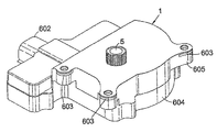
図1から図4に示すように、自動車の窓巻上げ機構用の電気アクチュエータ1は、従来の窓巻上げ機構(図示せず)を駆動するために出力結合歯車5が配置された減速歯車装置4を駆動する一体フライホイールと遠心クラッチ装置3とに駆動的に結合される電気モータ2を有する。これらの構成要素は、この例では2つの合わせシェル(mating shells)604,605がOリングシール606で封されたハウジング6内に配置されている。2つの合わせシェル604,605は、ネジ607によって共に保持されている。ハウジングはガラスが満たされたプラスチック材料(glass-filled plastics material)であり、図4に別に示されたように、構造に対して特に剛性を与えるスチールの保持(retention)挿入板603を有する。保持挿入板603の3つのリムは開口608によって形成されており、この開口がハウジング内の対応する形成体(formations)と協働して全体のアクチュエータ組み立て物が車両内で3点で取り付けられることを可能にする。保持挿入板603と一体的に形成されたスピンドル609は、出力結合歯車5を支持する。
As shown in FIGS. 1 to 4, an electric actuator 1 for an automobile window winding mechanism includes a reduction gear device 4 in which an
外部からの電気配線接続が、適切なシールを用いてポート603を通り、ハウジングへ入る。以下で説明するように、これらの配線は電気モータ2に電流を供給し、ウォームギヤ402に設けられた磁石リング403に隣接する、ホール効果センサまたはリード(reed)スイッチといった電子センサ(図示せず)とつながっている。
External electrical wiring connections enter the housing through
遠心クラッチ3の出力駆動ドッグ(dog)は、電気モータ駆動スピンドルとフライホイール装置3と同軸であり、同軸のウォームギヤ401を駆動する。電気モータ2、フライホイールと遠心クラッチ装置3、及び、伸びたウォームギヤ401は、ハウジング6の一端に沿って同軸に形成されている。協働するウォームギヤ402は、回転のために、モータ2の軸と垂直な(normal)ハウジングの中心のスピンドルに取り付けられている。このギヤ402はアクチュエータの単一のもっとも大きな構成要素であり、従って、ハウジングは一般的には平坦で矩形に製造されている。
The output drive dog of the
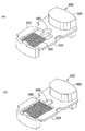
図5(a),5(b),5(c)に示されたように、位置を検出するために、大きなウォームギヤ402は、リング磁石403を保持する円形のチャンネル4031を有している。72個の磁石がリング403の周囲に等角度で配列されており、それにより、360°にわたって分散された144の磁極を構成する。ハウジングに取り付けられたリング403上のホール効果センサーは、磁極の通過を検出するために使用され、そしてギヤ402の回転のスピードと方向を決定するために、ホール効果センサーからの電気信号を受ける外部制御回路(図示せず)が使用される。アクチュエータによって展開されたトルクはスピードの関数であり、その関数は電気制御回路内であらかじめ決められ、記憶されており、それにより、例えば、アンチ・ピンチ安全(anti-pinch safety)のために出力トルクを制限するようにトルクが制御され得る。ギヤの位置が決定されると、窓の位置が決定され得る。
As shown in FIGS. 5 (a), 5 (b), and 5 (c), the
図5(a),5(b)に示したように、大きなウォームギヤ402は、磁石リングから離れた以外の3つの構成要素を有している。これらの構成要素は同軸上に互いに向き合っている。駆動構成要素402は外歯を有し、この外歯は伸びたウォームギヤ401と噛み合う。駆動されるらせん状のスパー・ピニオン(spur pinion)404は、被駆動(従動)板410に形成されており、ゴム製の粘着制振円板420が構成要素402と410の間に保持され、これらの間で弾性的に変形可能な粘着制振を提供し、アクチュエータがデッドエンドに当たったときにバックラッシュを最小にする。この例では、ゴムの材料は圧縮率がA90ショア(shore)、すなわち約50Dの合成ゴムであり、これには、「Hytrel」または「Santoprene(登録商標)」がある。ゴム円板420は、この例では、ノッチによって分割された8つの等しい45°セクターから構成されており、ノッチのうち4つ421は一方の側にあり、ノッチのうち他の4つ422は他方の側にある。これらのノッチは、対応するギヤ構成要素402及び410の内面に形成された放射状のリブと係合する。それ故、構成要素402及び410の相対的な回転運動が存在するときに、リブはゴム円板420の個々のセクターを圧縮または圧迫する(compress or squeeze)。もちろん、90°セクターのように、セクターの数が異なっていてもよく、このことは適切な設計事項である。ひとつだけの弾性ブロックであってもよい。
As shown in FIGS. 5 (a) and 5 (b), the
らせん状のスパー・ピニオン404は、スピンドル609を共有し、出力ピニオン5と同軸かつ堅く結合したらせん状のスパー・ギヤ405を駆動する。図2に示したように、回転のために大きなウォームギヤ402は、保持挿入体603と対向するハウジングシェル604の間に取り付けられる。
The
ハウジングの材料と剛構造とその内部構成要素についてはアクチュエータの動作の円滑を最大にし、その音響出力を最小にするように選択される。ゴム制振は、バックラッシュを最小にすると共に、窓からの振動と電気モータの振動とを分離する役目もする。しかし、ゴム円板420の弾性変形性は、遠心クラッチの係合点においてアクチュエータによって与えられる「打撃(キック)」、すなわち、衝撃駆動を弱めるよりもむしろ、負荷における静摩擦に打ち勝つのに重要となる。
The housing material and rigid structure and its internal components are selected to maximize the smoothness of the actuator operation and minimize its acoustic output. Rubber damping minimizes backlash and also serves to separate the vibration from the window from that of the electric motor. However, the elastic deformability of the
図3において、最も明らかに示されるように、スチールの挿入体603は、構造体の層を分離するさらなる効果を有する。我々は、このように組立物の層の「サンドイッチ」は、層間の接触面が構造体を横切るノイズの伝達を分散する傾向があり、有利な音響効果を有することを見出した。振動ノイズは、スチールの挿入体603とハウジングの合わせシェル604,605との間の平面界面において一層容易に吸収される。シェル604,605はスチールの挿入体603の弾力性と異なる弾力体で製造されることが重要である。
As shown most clearly in FIG. 3, the
電気モータ2が、図6における、一体的なフライホイールと遠心クラッチ装置3と一緒に示されている。フライホイールとクラッチ装置3は円板の形状、すなわち、本質的に円筒形状であり、モータ駆動軸304に対して同軸に形成され、出力駆動ドッグ303と同軸である。円板形状のフレーム301はその直径を横切ってチャンネルを有しており、塊状の(massive)拡大体が両端にあり図9(a)と図9(b)にそれぞれ係合と非係合の位置が示されたジグザグの圧縮ばね350によって非係合位置に向けて弾性的に偏らされた(biased)遠心スライダー302がそのチャンネル内をスライドする。英国出願、GB−A−2393958に記載されているように、ばね350は全体が遠心スライダー302内に凹陥されており、ばねの一端が開口340を通り抜けたモータスピンドルをスライダーの中心において押し付ける。
The
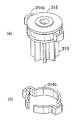
図6に示された例示において、遠心クラッチの被駆動構成要素は、モータ軸304に同軸に装着された駆動ドッグ303であり、当該ドッグは等角度間隔で配置された3つの歯を有している。図7と図8に示された代替的な例では、駆動ドッグ313は歯車(toothed cog)313と一体的に形成された円板315に装着された単一の歯314を有している。遠心クラッチの被駆動構成要素は、特定の実施形態にて要求される減速ギヤ装置に結合するように構成されており、図1と図2の実施形態では、駆動ドッグ314は、いずれかの歯車313を経由するよりも、伸びたウォームギヤ401に直接的に接続されている。
In the illustration shown in FIG. 6, the driven component of the centrifugal clutch is a
図7から図9に最も明確に示されているように、遠心スライダー302は、円筒形状(cylindrical)の駆動要素301の直径にわたって形成されたチャンネルを横切ってスライドするようにレールによって拘束されている。このチャンネル330は、遠心スライダー302の中心線に沿って形成された補完的に突出しているランド323を案内する中央軸溝(groove)331によって形成される。遠心スライダー302のそれぞれの側部にそって突き出ているレール323は、円筒形状のベース部301内のチャンネルに沿って対応する形成体相互間に案内されている。
As best shown in FIGS. 7-9, the
遠心スライダー302は、一方の端において塊状の(massive)拡大体320を有しており、当該拡大体は釣鐘おもり(bell weight)として作用して、図7(a)と図8(a)に示されているように、圧縮ばね350の力に抗してスライダーを図7(b)と図8(b)に示されたその非係合位置から係合位置に向けて引っぱる。係合位置においては、塊状の拡大体320はベース部301の円筒外表面と同一面となる部分的な円筒の外表面を有しており、拡大体320はベース部301のリム(rim)を補完している。リムは塊状の拡大体320がチャンネル330内をスライドするチャンネル330の幅に対応する開口303を有しており、その拡大体が係合位置に到達したときにそのすき間を実質的に埋める。この係合位置において、遠心スライダー302は放射状の端部係止に到達し、係合ドッグ321は駆動ドッグ314と係合する。この係合点において、クラッチの駆動要素および被駆動要素が相互にロックし、回転運動をドッグ313に伝達する。
遠心スライダー302の反対側の端には、ドッグ321と一体になった塊状の拡大体がさらに存在しており、クラッチの完全な非係合位置では、図7(b)と図8(b)に示したように、拡大体は円筒形状のベース301のリムのすき間にあり、拡大体の部分円筒外側表面はリムの円筒形状の表面と同一面となる。その時には、遠心スライダー402は、端部係止に当接している。
At the opposite end of the
クラッチが係合する回転スピードは、クラッチの構成要素の構造と圧縮ばね350のばね強度によってあらかじめ選択されている。
The rotational speed at which the clutch is engaged is selected in advance according to the structure of the components of the clutch and the spring strength of the
クラッチが、当該クラッチが係合位置へ加速されるとき、回転エネルギーを蓄積できるフライホイールを構成することは、本発明の重要な要素である。フライホールの重要な構成要素は、円筒形状のベース301の大きなリムと、遠心スライダー302の補完的な塊状の拡大体320,321である。このことは、モータが非常に軽量のロータを用いることを可能にする。
It is an important element of the present invention that the clutch constitutes a flywheel capable of storing rotational energy when the clutch is accelerated to the engaged position. The important components of the flyhole are the large rim of the
図7(a)と図8(a)に示されたようにクラッチが完全に係合したときに、組合されたクラッチ装置3の慣性の中心は、回転の軸、すなわち、モータスピンドルに配置されるように、塊状の拡大体320,321は精密に配置される。遠心スライダー302の他の位置において、慣性の中心はレール331の直径に沿って軸の位置からずれた所に移る。この装置が重要なのは、一旦クラッチが係合し、電気モータが負荷を駆動すると、騒音や応力を最小にするために、クラッチは回転的に釣り合いが完全に取れることである。休止から係合位置への装置の加速の期間では、負荷がかかっていないので、クラッチが回転的に釣り合いが取れることは重要なことではない。
When the clutch is completely engaged as shown in FIGS. 7 (a) and 8 (a), the center of inertia of the combined
遠心クラッチの出力駆動ドッグの代替的な形態が図10から図13に示される。図10(a)と図10(b)は、図7と図8の駆動ドッグを示している。小さな歯車313が当接(alentment)キャップ314,315に接続されており、これらのキャップは2単位などの他にコールド形成ユニットまたは射出成形ユニットとして形成することができる。キャップ315の溝の周りに留められるばね314の中心部として犬歯(dog tooth)が形成される。ばね314とキャップ315の溝との間の円筒界面にわたる摩擦係合は、クラッチの駆動要素から被駆動要素へ出力駆動を回転的に伝達する。摩擦は十分強く、アクチュエータの駆動の状態に欠陥条状態があったり、アクチュエータが端部係止に至らなければ、相対的な回転運動は抵抗を受けない。この緩衝ばね装置は、過度の磨耗や損傷を防ぐためにすべりが許容される。この摩擦は十分強く、クラッチは依然として強力な「打撃(キック)」や衝撃力(impressive force)を発生させることができ、アクチュエータによって駆動される負荷の静摩擦に打ち勝つことができる。
An alternative form of centrifugal clutch output drive dog is shown in FIGS. 10 (a) and 10 (b) show the drive dog of FIGS. 7 and 8. FIG.
図11(a)と図11(b)に示された代替的な装置では、キャップ315は同一形状をしているが、ばね314aは、外方向に曲がった端部を有し円筒形状となっていない、すなわち、ばねの端部は、ばねの中心が犬歯を形成するのではない。係合によって、ばね314aは圧縮される傾向があり、キャップ315周囲の摩擦把持(grip)が増加する。
In the alternative device shown in FIGS. 11 (a) and 11 (b), the
さらに代替的な装置が図12(a)と図12(b)に示されている。そこには、ひし形をしたばね314bは対向する対角位置に2つの歯を構成する。ばねは一つの開口を一方の側に有し、溝中でキャップ315を覆うように配置できるようにする。2つの歯を有することの利点は、二つの歯が回転的に釣り合いを取れることである。
A further alternative device is shown in FIGS. 12 (a) and 12 (b). There, the diamond-shaped
摩擦すべりを許容する代わりに、図13の装置は弾性ひずみに対抗した相対的な回転運動を許容し、ねじりコイルばね130にポテンシャルエネルギーを蓄積する。当該ばねは時計のばね(clock spring)と同様の機能をし、その後に続く制御された解放のためにエネルギーを蓄積する。この例では、ばねは10mm幅で0.5mm厚とすることができ、巻き戻されるときに10kWの出力を伝搬することができる。それ故、クラッチの出力駆動部材はギヤ313の形状をした結合部材を有しており、車両のエンジンなどの負荷を駆動する。それはまた、遠心スライダーと係合できる一対の直径方向に対向した歯141,142を有するドッグ140を有している。
Instead of allowing frictional sliding, the device of FIG. 13 allows relative rotational movement against elastic strain and stores potential energy in the
図13に示されたように、歯141はスライダーと係合し、矢印143で示される力を生成する。ドッグ140は歯142にて他端146がギヤ313に接続されたねじりばね130の一端145に接続される。矢印144で示されるように、ばね130を歯142は駆動する。
As shown in FIG. 13, the
この配列によってねじりばね130内のポテンシャルエネルギーの中間的な(intermediate)蓄積によってフライホイールの回転慣性を長期間にわたって衝撃的に移送することができる。フライホイールから負荷へのトルクの伝達はこうして長期間平滑化され、トルクの時間積分として表される全衝撃をほぼ維持しながら衝撃的な「打撃(キック)」のトルクレベルを減少させる。
With this arrangement, the rotational inertia of the flywheel can be shockedly transferred over a long period of time by the intermediate accumulation of potential energy in the
∫Idt ∫Idt
始動モータは、図6〜図9の電気モータとフライホイールの原理が類似する電気モータとフライホイールを有しているが、窓巻き上げ機構に必要な出力よりも大きな出力となっている。フライホイールは図13の出力装置を有する。出力ギヤ(通常は駆動歯車といわれる)がエンジンのフライホイールと結合されている。当該フライホイールは好適に始動モータの駆動歯車と噛み合うギヤ(代表的なギヤ比は20:1)に適用される。 The starter motor has an electric motor and a flywheel similar in principle to the electric motor and the flywheel shown in FIGS. 6 to 9, but has a larger output than that required for the window winding mechanism. The flywheel has the output device of FIG. An output gear (usually called the drive gear) is coupled to the engine flywheel. The flywheel is preferably applied to a gear (typical gear ratio is 20: 1) that meshes with a drive gear of a starter motor.
始動モータは最初のエンジン回転に必須である。エンジン組立部品のかなりの静摩擦と動摩擦のために、エンジンの構成要素、クランクシャフト、エンジンフライホイール、ピストンが動くようにするために、始動モータはバッテリーからのかなりの電力の取り込みが必要である。始動モータはバッテリーに蓄えられた電気エネルギーを使用して、クランクシャフトの一端にボルト止めされたフライホイールを回転させる。回転しているフライホイールは、ひき続いて始動モータとは独立に機能するピストンの運動を行わせる。 A starter motor is essential for the first engine revolution. Due to the significant static and dynamic friction of the engine assembly, the starter motor needs to draw significant power from the battery in order for the engine components, crankshaft, engine flywheel and piston to move. The starter motor uses electrical energy stored in the battery to rotate a flywheel bolted to one end of the crankshaft. The rotating flywheel subsequently causes a piston motion that functions independently of the starting motor.
例として、1200ccエンジンの車は、350Aもの瞬間電流を引き出す3ないし4kgの始動モータを有しており、3.7kgになり、その始動モータはエンジンが2100rpmの自由走行スピードのとき9V,155Aで0.25kg.mの走行トルクを供給し、その最高出力は0.8kWである。本発明の利点により、10mm幅で0.5mm厚の10kWを生成するねじればねが付いたフライホイールが300gでモータが600gのわずか重さ1.2kgの始動モータで同一の車を始動できる。電気モータへの瞬間電流のすぐ後に、始動モータは10ないし12Nmのトルクを供給し、4ないし5Nmの定常トルクまで下がる。当該モータは12Vで最大36A、定格9Aを消費する。従来の車は20Amp.hourの容量のバッテリーを必要とするのに対して、当該車は5ないし6Amp.hourのバッテリーの使用で十分である。始動モータとバッテリーの重さの節減は明らかに意義がある。 As an example, a car with a 1200 cc engine has a 3-4 kg starter motor that draws an instantaneous current of 350 A, which is 3.7 kg, which is 9V, 155 A when the engine is at a free running speed of 2100 rpm. 0.25 kg. m running torque is supplied, and its maximum output is 0.8 kW. Due to the advantages of the present invention, the same car can be started with a starter motor weighing only 1.2 kg, 300 g of screwed flywheel producing 10 kW of 10 mm width and 0.5 mm thickness and a motor of 600 g. Immediately after the instantaneous current to the electric motor, the starting motor supplies a torque of 10 to 12 Nm and drops to a steady torque of 4 to 5 Nm. The motor consumes a maximum of 36A and a rating of 9A at 12V. The conventional car is 20 Amp. Hour capacity battery is required, but the car is 5-6 Amp. The use of a hour battery is sufficient. Clearly, the weight savings of the starting motor and battery are significant.
トラックの始動モータの例では、始動モータの重さは35kgからその3分の1より減らすことができる。必要電流の低減の割合は、車に対する始動モータで達成されたものに匹敵する。より軽い重さのバッテリーをトラックに使用することもできる。 In the truck starter motor example, the starter motor weight can be reduced from 35 kg to less than one third. The rate of reduction of the required current is comparable to that achieved with the starting motor for the car. A lighter weight battery can also be used for the truck.
アクチュエータの動作を説明する。図面に示された様々な代替的な構成要素は、図1から図3の対応する要素に代えることができる。さらに、図1から図3に示された特定の減速ギヤ装置は本質ではなく、この例のような2段のまたは異なる段数がある多くの違った装置が可能である。 The operation of the actuator will be described. Various alternative components shown in the drawings can be replaced by corresponding elements of FIGS. Furthermore, the particular reduction gear device shown in FIGS. 1 to 3 is not essential, and many different devices with two or different stages, such as this example, are possible.
車の窓を巻き上げたり巻き下げる必要があるとき、対応するスイッチが操作される、これにより、図1と2のアクチュエータへ送られる電力を制御する電子制御ユニットを順次集中的に制御する。磁石円板403上のホール効果センサーから得られたアクチュエータ1内のセンサーからの制御信号を使用して、電子制御ユニットは窓の位置についての情報も記憶する。類似の位置検知装置は、我々のWO03/004810とGB−A−2381034の特許出願に開示されている。
When the car window needs to be rolled up or down, the corresponding switch is actuated, thereby successively and centrally controlling the electronic control unit that controls the power delivered to the actuators of FIGS. Using the control signal from the sensor in the actuator 1 obtained from the Hall effect sensor on the
位置フィードバック検知装置が窓が所望の位置に到達したと決定されたり、電気駆動が突然終了して例えばピンチ状態といった不良条件が送られてきたりするまで、電力は電気モータを駆動する。 The electric power drives the electric motor until the position feedback detector determines that the window has reached the desired position, or until the electric drive is suddenly terminated and a fault condition, such as a pinch condition, is sent.
電力が電気モータ2に供給されているとき、フライホイールとクラッチ装置はクラッチが係合するスピードになるまで加速する。係合したとき、回転エネルギーが減速ギヤに一部送られ、相当な「打撃」あるいは衝撃として負荷に送られる。これは、例えば窓枠駆動レバーと耐候性(weather-proofing)ドア構造における窓ガラスの縁にある摩擦といった、負荷に固有の静摩擦に打ち勝つことに利点がある。クラッチの連続した動きは負荷を加速し始める。電気モータは、負荷が一定速度で動き続ける最大出力になるまで加速し続ける。電子制御ユニットは、負荷の位置を監視し、この場合は窓の負荷が一旦所望の位置に到達したり、走行効果を見込んでその位置に到達する少し前で電力を止める。負荷からの過度な抵抗があると、
電気モータへ継続する電力がクラッチをもう一度係合としさらに衝撃力を供給できるように、その負荷はクラッチを減速し、これを非係合とする。したがって、必要ならば、連続する衝撃を負荷に続けざまに供給し、摩擦に打ち勝つ。
When electric power is supplied to the
The load decelerates the clutch and disengages it so that continued power to the electric motor can engage the clutch once again and provide additional impact force. Therefore, if necessary, a continuous shock is continuously applied to the load to overcome the friction.
フライホイールに蓄えられる回転エネルギーの量、そしてしかるに係合時の衝撃力の強さは、クラッチ内のばね強度を選択することであらかじめ決められるが、フライホイール質量、回転の中心からの距離、モータの出力とスピード(電圧や電流の定格の選択による)そして、モータの加速の度合いを適切に選択することで決めてもよい。アクチュエータは、上記のように非常に多種類の異なった用途のために設計できる。車の窓を駆動するために図1と図2に示されたウォームギヤ一式を使用することは、その非常に高い機構上の利点が窓の重さに耐えるのに役立ち、減速ギヤの摩擦による反対の動きに対抗する点で有用であるのであるが、ウォームギヤを使用するのは必須でない。 The amount of rotational energy stored in the flywheel, and the impact strength when engaged, is determined in advance by selecting the spring strength in the clutch, but the flywheel mass, distance from the center of rotation, motor It may be determined by appropriately selecting the output and speed of the motor (by selecting the voltage and current ratings) and the degree of motor acceleration. Actuators can be designed for a very wide variety of different applications as described above. Using the worm gear set shown in FIGS. 1 and 2 to drive the car window helps its very high mechanical advantage to withstand the weight of the window and counteract the friction of the reduction gear However, it is not essential to use a worm gear.
用途によっては、例えば1mm又は100mmきざみのパルス状の駆動をすることが有用となる。ギヤ比によっては、アクチュエータはエレベータにおいてわずか1グラムの重さ又は300kgの重さを持ち上げるのに当該アクチュエータを使用することができ、スピードは適切なフィードバック機構によって制御できる。 Depending on the application, for example, it is useful to drive in pulses of 1 mm or 100 mm. Depending on the gear ratio, the actuator can be used to lift as little as 1 gram or 300 kg in the elevator and the speed can be controlled by a suitable feedback mechanism.
歯車内の緩衝装置、例えば、図5のゴム製ブロック420は、駆動が係止に当たったとき、バックラッシュの好ましくない効果を軽減する。ゴム製ブロックは歯車装置からの騒音も吸収する。
A shock absorber in the gear, such as the
説明したように、遠心クラッチの駆動ドッグ内の緩衝ばね機構は、過負荷に安全である。しかし、ばね機構はモータからの軸の振動を制振するという利点もある。説明したように、ドックは何本の歯、すなわち、図6に示した3本でも、図7に示した1本でも、図12に示した2本でも、あるいは他の何本でも、有していてもよい。等角度間隔の複数の歯があれば、全組み立て体が駆動されているとき、良好な回転のつりあいが提供される。 As explained, the buffer spring mechanism in the drive dog of the centrifugal clutch is safe from overload. However, the spring mechanism also has an advantage of suppressing the vibration of the shaft from the motor. As explained, the dock has any number of teeth, ie three as shown in FIG. 6, one as shown in FIG. 7, two as shown in FIG. 12, or any other number. It may be. Having a plurality of equiangularly spaced teeth provides good rotational balance when the entire assembly is driven.
また、駆動ドッグには、駆動ドッグと被駆動部品の間にゴム製のダンパーや他の弾性材料をモータの軸と水平にまたは同軸方向に挟むことによって、窓巻き上げ機構の大きな歯車402に類似した形式の弾性制振を配置することができる。この駆動ドッグ制振は、大きな歯車402の弾性制振の代わりまたはそれに付加したものとなる。
The drive dog is similar to the
この例では、ハウジングはゴム製シールとネジによって封されている。しかし、そのかわりに、耐水性を供するため、ハウジングは例えば国際標準IP67の超音波溶接がされてもよい。 In this example, the housing is sealed with a rubber seal and screws. Alternatively, however, the housing may be ultrasonically welded to, for example, international standard IP67 to provide water resistance.
従来の窓アクチュエータに対する本発明の利点を説明するために、同等の装置に対するモータ定格を比較することが有益である。従来の車の窓アクチュエータは36アンペアの代表的なストール電流、12Vでの定格9アンペア、約10ワット産生に10%効率で動作するモータを有している。これは、1Nmの連続トルクを発生し、12Nmの脱離トルクがある。本発明の利益により、より一層小さいモータを使用でき、2.8アンペア定格でありながら、ストール・トルクが15Nmで6Nmの連続トルクを産生する。従来のアクチュエータはクラッチが無く、フライホイールエネルギー蓄積効果がない。 To illustrate the advantages of the present invention over conventional window actuators, it is beneficial to compare motor ratings for comparable devices. Conventional car window actuators have a typical stall current of 36 amps, a rating of 9 amps at 12 volts, and a motor that operates at 10% efficiency for about 10 watts production. This generates a continuous torque of 1 Nm and a desorption torque of 12 Nm. With the benefits of the present invention, even smaller motors can be used, producing a continuous torque of 6 Nm with a stall torque of 15 Nm while being 2.8 ampere rated. Conventional actuators do not have a clutch and have no flywheel energy storage effect.
本発明の利用により、アクチュエータの大きさと重さを相当に減らすことができる。例えば、窓アクチュエータでは、モータの重さを640gからわずか40gに減らすことができ、モータを含んだ全アクチュエータ組立体は、代表的な740gから200gに減らすことができる。容積は半減以上になり、価格とエネルギー消費は相当かなり減らせる。小さなモータを使用することは、アクチュエータをかなり静かにさせ、クラッチと減速装置内の制振機構は、騒音低減に貢献する。構造の必要な強度は、スチールの挿入体を使用することで達成でき、ハウジングの残りをより軽いガラスが充満されたプラスチック材料とすることができる。 By utilizing the present invention, the size and weight of the actuator can be significantly reduced. For example, in a window actuator, the weight of the motor can be reduced from 640g to only 40g, and the total actuator assembly including the motor can be reduced from a typical 740g to 200g. The volume is more than halved, and the price and energy consumption can be considerably reduced. Using a small motor makes the actuator quite quiet, and the damping mechanism in the clutch and speed reducer contributes to noise reduction. The required strength of the structure can be achieved by using a steel insert, and the remainder of the housing can be a plastic material filled with lighter glass.
自動車の始動モータにおける本発明の利用を説明する。上述したように、始動モータは、エンジンに結合しているのでかなりの慣性を有している。そして、初期加速の過程の低速時に大きな動摩擦抵抗がある。ねじりばね130内で回転エネルギーの中間的な蓄積によって、長期にわたって印加されたトルクを分散することが必要である。車の点火スイッチを起動させたとき、リレーが電気モータ2をカーバッテリーに接続し、クラッチホイールが加速し、そして係合する。これがばね130を駆動し、ばね130は歯車313を駆動してエンジンを回転させる。まずばねが巻き上がりそして巻き戻されると、フライホイールに蓄積されたエネルギーを使いながら、トルクが歯車313に連続的に伝達される。モータ2に供給される連続した電力は、エンジンを更に加速するため歯車313の駆動を維持する。そして、エンジンが点火するまでエンジンの回転を続けるために電気モータ2の最大電力でエンジンがいったん一定のスピードに達すると、クラッチはオーバーランし電気モータは電源オフになる。
The use of the present invention in an automobile starter motor will be described. As mentioned above, the starter motor has significant inertia because it is coupled to the engine. There is a large dynamic frictional resistance at low speed during the initial acceleration process. It is necessary to distribute the applied torque over time due to the intermediate accumulation of rotational energy within the
本発明の他の多数の用途として、電気モータとクラッチホイールは歯車装置を使用しないで、負荷に直接使用することができる。一つの例が、例えば道路面の掘削に使用する形式の空気削岩機用の空気駆動のかわりに本アクチュエータの使用がある。電気モータとクラッチホイールによって回転される駆動ドッグが、他の従来の削岩機の削岩ビット組立体に周期的に係合するように配置される。駆動ドッグを通じたこの「打撃駆動」は削岩ビットを衝撃的に持ち上げ、そして、削岩されている面にビットを落下させる。そしてドッグの次の回転係合によってそのサイクルが繰り返される。あるいは、この打撃駆動は削岩ビットを下向きに打撃してドリルビットを被掘削面に強打する。この後、削岩ビットを上向きに跳ね返す衝撃反動力を提供し、衝撃削岩効果があるそのサイクルを繰り返させる。こうして、駆動ドッグはビット組立体に直接、あるいは削岩フレームのビットにつながっているばねを介して、結合させることができる。このハンマー効果は、ハンマードリルのような他の道具に適用できる。そして、手持ち工具や大型産業用工具そして機械工具に適用できる。 In many other applications of the present invention, the electric motor and clutch wheel can be used directly on the load without the use of gearing. One example is the use of this actuator instead of an air drive for an air rock drill of the type used, for example, for excavating road surfaces. A drive dog that is rotated by an electric motor and a clutch wheel is arranged to periodically engage the rock bit assembly of other conventional rock drills. This “striking drive” through the drive dog lifts the rock drilling bit impactfully and drops the bit onto the surface being rock drilled. The cycle is then repeated with the next rotational engagement of the dog. Alternatively, in this driving operation, the rock drill bit is hit downward and the drill bit is struck against the drilled surface. After this, an impact reaction force that bounces the rock drill bit upward is provided, and the cycle having the impact rock drill effect is repeated. Thus, the drive dog can be coupled directly to the bit assembly or via a spring connected to the bit of the rock drilling frame. This hammer effect can be applied to other tools such as a hammer drill. And it can be applied to hand-held tools, large industrial tools and machine tools.
1…アクチュエータ、 2…モータ、 3…遠心クラッチ、 5…出力歯車、 6…ハウジング、 140…ドッグ、 141…歯、 143…矢印、 144…矢印、 145…一端、 146…他端、 301…ベース、 302…遠心スライダー、 303…駆動ドッグ、 304…モータ駆動軸、 313…小さな歯車、 314…キャップ、 315…キャップ、 320…拡大体、 330…チャンネル、 331…レール、 340…開口、 401…ウォームギヤ、 402…大きなウォームギヤ、 403…リング、 404…ピニオン、 410…被駆動円板、 420…ブロック、 421…切り欠き、 422…切り欠き、 603…挿入板、 604…ハウジング・シェル、 605…ハウジング・シェル、 606…Oリング、 607…ネジ、 608…開口、 609…スピンドル DESCRIPTION OF SYMBOLS 1 ... Actuator, 2 ... Motor, 3 ... Centrifugal clutch, 5 ... Output gear, 6 ... Housing, 140 ... Dog, 141 ... Teeth, 143 ... Arrow, 144 ... Arrow, 145 ... One end, 146 ... Other end, 301 ... Base , 302 ... centrifugal slider, 303 ... drive dog, 304 ... motor drive shaft, 313 ... small gear, 314 ... cap, 315 ... cap, 320 ... enlarged body, 330 ... channel, 331 ... rail, 340 ... opening, 401 ... worm gear 402: Large worm gear, 403 ... Ring, 404 ... Pinion, 410 ... Driven disk, 420 ... Block, 421 ... Notch, 422 ... Notch, 603 ... Insertion plate, 604 ... Housing shell, 605 ... Housing Shell, 606 ... O-ring, 60 7 ... Screw, 608 ... Opening, 609 ... Spindle
Claims (42)
前記遠心クラッチは、
一端に塊状の拡大体(massive enlargement)と、第1の結合用形成体と、を有する遠心スライダーと、
前記遠心スライダーを支持する形態で形成されたフレームであって、前記遠心スライダーが拡大された直径の位置と縮小された直径の位置との間で滑動することを抑制し、当該フレームの滑動の軸と直角な軸によって、前記遠心スライダーによって駆動されるべき前記駆動軸に固定的にフィットするよう形成体(formation)に形成されたフレームと、
前記駆動軸上で自由に回転するように装着可能で、使用時において前記駆動部材との係合を駆動するように形成され、そして前記遠心スライダーが拡大位置にあるときにのみ前記第1の結合用形成体と駆動的に接続する第2の結合用形成体によって形成された出力駆動部材と、
前記遠心スライダーをその縮小位置の方へ偏らせる手段(means for biasing)と、
を有し、
それにより、前記遠心スライダーと前記フレームの回転によって前記塊状の拡大体が前記スライダーをその前記縮小された直径の位置から前記拡大された直径の位置に直径方向に引き寄せることにより前記第1の結合用形成体と前記第2の結合用形成体とを相互に係合させることで回転運動を前記駆動軸から前記出力結合ギヤへ伝達させ、前記回転が停止したときには前記偏らせる手段が非係合とすることで前記駆動軸を前記出力結合ギヤから非結合とする、遠心クラッチにおいて、
前記フレームと前記スライダーは前記駆動シャフト軸上でフライホイールを構成するために協働し、前記遠心スライダーがその拡大された直径の位置にあるときにのみ、前記遠心クラッチの慣性中心が同軸上にあって、その回転は前記クラッチが係合したときに完全に釣り合いが取れることを特徴とする、
遠心クラッチ。 A centrifugal clutch in which a drive shaft is coupled to a driven member at a rotational speed above a predetermined threshold;
The centrifugal clutch is
A centrifugal slider having a massive enlargement at one end and a first binding formation;
A frame formed to support the centrifugal slider, wherein the centrifugal slider is prevented from sliding between an enlarged diameter position and a reduced diameter position; A frame formed in a formation so as to fit securely to the drive shaft to be driven by the centrifugal slider by an axis perpendicular to
The first coupling is mountable for free rotation on the drive shaft, is configured to drive engagement with the drive member in use, and the first coupling only when the centrifugal slider is in an expanded position An output drive member formed by a second coupling forming body that is drivingly connected to the forming body;
Means for biasing the centrifugal slider toward its reduced position (means for biasing);
Have
As a result, when the centrifugal slider and the frame rotate, the massive expansion body draws the slider from the reduced diameter position to the enlarged diameter position in the diametrical direction. When the forming body and the second coupling forming body are engaged with each other, the rotational motion is transmitted from the drive shaft to the output coupling gear, and when the rotation stops, the biasing means is disengaged. In the centrifugal clutch, the drive shaft is decoupled from the output coupling gear,
The frame and the slider cooperate to form a flywheel on the drive shaft axis, and the center of inertia of the centrifugal clutch is coaxial only when the centrifugal slider is in its enlarged diameter position. And the rotation is completely balanced when the clutch is engaged,
Centrifugal clutch.
前記遠心クラッチは、
前記駆動軸上にフライホイールを構成するために協働するフレームと遠心スライダーと、
使用時に前記被駆動部材を駆動する結合部材と、
を有し、
前記フライホイールは結合用部材を駆動するために回転的に結合され、制限された相対的な回転運動がそれらの間で許容される、
遠心クラッチ。 A centrifugal clutch in which a drive shaft is coupled to a driven member at a rotational speed above a predetermined threshold;
The centrifugal clutch is
A frame and a centrifugal slider that cooperate to form a flywheel on the drive shaft;
A coupling member that drives the driven member when in use;
Have
The flywheels are rotationally coupled to drive the coupling members and limited relative rotational movement is permitted between them;
Centrifugal clutch.
Applications Claiming Priority (2)
| Application Number | Priority Date | Filing Date | Title |
|---|---|---|---|
| GB0504676A GB2424045A (en) | 2005-03-07 | 2005-03-07 | Centrifugal clutch which is rotationally balanced when engaged |
| PCT/GB2006/000455 WO2006095126A1 (en) | 2005-03-07 | 2006-02-09 | Centrifugal clutch and actuator |
Publications (2)
| Publication Number | Publication Date |
|---|---|
| JP2008531955A true JP2008531955A (en) | 2008-08-14 |
| JP2008531955A5 JP2008531955A5 (en) | 2009-04-02 |
Family
ID=34451945
Family Applications (1)
| Application Number | Title | Priority Date | Filing Date |
|---|---|---|---|
| JP2008500248A Pending JP2008531955A (en) | 2005-03-07 | 2006-02-09 | Centrifugal clutch and actuator |
Country Status (6)
| Country | Link |
|---|---|
| US (1) | US20080121489A1 (en) |
| EP (1) | EP1859177A1 (en) |
| JP (1) | JP2008531955A (en) |
| CN (1) | CN100585208C (en) |
| GB (1) | GB2424045A (en) |
| WO (1) | WO2006095126A1 (en) |
Cited By (2)
| Publication number | Priority date | Publication date | Assignee | Title |
|---|---|---|---|---|
| KR101235975B1 (en) | 2011-06-30 | 2013-02-21 | 주식회사평화발레오 | Clutch actuator with wear compensation function |
| CN112460314A (en) * | 2019-09-06 | 2021-03-09 | 精刻株式会社 | Actuator and exhaust valve drive device |
Families Citing this family (26)
| Publication number | Priority date | Publication date | Assignee | Title |
|---|---|---|---|---|
| GB2415994B (en) * | 2004-07-06 | 2006-07-19 | John Phillip Chevalier | Latch arrangement |
| GB2464999A (en) * | 2008-09-16 | 2010-05-12 | John Phillip Chevalier | An actuator including a motor connected to rotate a flywheel carrying the input of a centrifugal clutch |
| IT1393520B1 (en) * | 2009-03-24 | 2012-04-27 | So Ge Mi Spa | AUTOMATIC CLOSURE DEVICE PERFECTED BY VEHICLE DOOR. |
| KR20110072877A (en) * | 2009-12-23 | 2011-06-29 | 현대모비스 주식회사 | Electronic parking brake actuator |
| TWI397641B (en) * | 2010-04-06 | 2013-06-01 | King Zone Corp | A clutch with high binding ability |
| EP2559335B1 (en) * | 2011-08-16 | 2014-08-13 | Black & Decker Inc. | A drive train for a hedge trimmer, a hedge trimmer and a method of controlling a hedge trimmer |
| DE102012013321A1 (en) * | 2012-07-06 | 2014-01-09 | Andreas Stihl Ag & Co. Kg | Portable, electrical implement |
| US9604602B2 (en) * | 2013-02-07 | 2017-03-28 | Trico Products Corporation | Wiper motor drive system having breakaway clutch |
| CN103527378B (en) * | 2013-10-31 | 2015-11-25 | 北京汽车研究总院有限公司 | A kind of engine cranking motor and vehicle |
| DE102015107725A1 (en) * | 2014-05-20 | 2015-11-26 | Asmo Co., Ltd. | Clutch motor and device for opening and closing an openable body |
| CN104186118B (en) * | 2014-08-28 | 2017-02-01 | 湖州思达机械制造有限公司 | Driven wheel overrunning clutch device for harvester |
| US9963112B2 (en) * | 2014-09-09 | 2018-05-08 | Ford Global Technologies, Llc | Window wiper system incorporating window moisture and torque sensors |
| TWI560375B (en) * | 2015-01-09 | 2016-12-01 | Kun Ming Li | Clutch and method for manufacturing clutch shoe of the clutch |
| CN105757140B (en) * | 2016-04-14 | 2018-08-24 | 广州市瑞翔机电有限公司 | A kind of retarding device |
| US10539112B2 (en) | 2016-04-28 | 2020-01-21 | Briggs & Stratton Corporation | Internal combustion engine with electric starting system |
| DE102016008561A1 (en) * | 2016-07-14 | 2018-01-18 | Thyssenkrupp Ag | Steering column with electro-mechanical fixing device |
| US10443662B2 (en) * | 2016-09-01 | 2019-10-15 | Ford Global Technologies, Llc | Mechanically coupled system with variable lever arm for torque coupling and decoupling between input and output |
| CN106545599B (en) * | 2016-12-21 | 2018-08-07 | 张家港川梭车业有限公司 | A kind of centrifugal mechanism for fluid drive |
| CN109667851B (en) * | 2017-09-01 | 2020-05-12 | 杭州富阳新堰纸制品有限公司 | Slide using bidirectional clutch |
| CN107448506B (en) * | 2017-09-30 | 2018-12-14 | 东莞市松研智达工业设计有限公司 | A kind of torque clutch based on centrifugation |
| KR20210049481A (en) * | 2019-10-25 | 2021-05-06 | 현대모비스 주식회사 | Parking brake apparatus for vehicle |
| IT202000004459A1 (en) * | 2020-03-03 | 2021-09-03 | Piaggio & C Spa | A PARKING BRAKE FOR A MOTORCYCLE AND MOTORCYCLE INCLUDING THE PARKING BRAKE |
| WO2021176467A1 (en) * | 2020-03-03 | 2021-09-10 | Preusse Powertrain Innovations Pvt Ltd | A dual action centrifugal clutch assembly and a method thereof |
| US11313339B2 (en) * | 2020-05-13 | 2022-04-26 | Leo Bair | Motor starting assembly |
| CN114396210A (en) * | 2021-12-28 | 2022-04-26 | 宁波奥云德电器有限公司 | Electric opening actuator for charging small door of new energy automobile |
| EP4311418A1 (en) * | 2022-07-29 | 2024-01-31 | Techtronic Cordless GP | Centrifugal clutch mechanisms |
Family Cites Families (44)
| Publication number | Priority date | Publication date | Assignee | Title |
|---|---|---|---|---|
| US1764317A (en) * | 1927-02-15 | 1930-06-17 | Bliss E W Co | Safety clutch |
| US2397700A (en) * | 1943-11-26 | 1946-04-02 | Sloan Lon | Flexible coupling |
| GB614078A (en) * | 1946-07-04 | 1948-12-09 | Rotax Ltd | Improvements relating to vehicle wind screen wipers |
| US2616274A (en) * | 1947-02-20 | 1952-11-04 | Landrum Porter | Power coupling |
| GB843095A (en) * | 1955-09-13 | 1960-08-04 | Newton & Bennett Ltd | Improvements in or relating to centrifugal friction clutches |
| GB842171A (en) * | 1956-07-07 | 1960-07-20 | Fichtel & Sachs Ag | Improvements in or relating to speed-responsive clutches |
| US3618730A (en) * | 1969-12-12 | 1971-11-09 | Vari Typer Corp | Torque-limiting clutch |
| US3810533A (en) * | 1973-07-02 | 1974-05-14 | Outboard Marine Corp | Torque reducing centrifugal clutch |
| US3970178A (en) * | 1973-09-04 | 1976-07-20 | Outboard Marine Corporation | Chain saw clutch with engaging and releasing centrifugal weights |
| US3953987A (en) * | 1975-01-22 | 1976-05-04 | Avco Corporation | Aircraft engine flexible fluid damped coupling |
| US4003458A (en) * | 1975-07-31 | 1977-01-18 | The United States Of America As Represented By The Secretary Of The Navy | Fail safe centrifugal clutch |
| FR2624575B2 (en) * | 1986-02-20 | 1991-10-18 | Rockwell Cim | CENTRIFUGAL CLUTCH FOR A LOCKING ACTUATOR OF A MOTOR VEHICLE DOOR LOCK |
| FR2594507B1 (en) * | 1986-02-20 | 1990-08-24 | Mecanismes Comp Ind De | CENTRIFUGAL CLUTCH FOR A LOCKING ACTUATOR OF A MOTOR VEHICLE DOOR LOCK |
| JPS6466467A (en) * | 1987-09-07 | 1989-03-13 | Aisin Seiki | Engine starter |
| DE3862640D1 (en) * | 1987-12-14 | 1991-06-06 | Rockwell Automotive Body Syst | CENTRIFUGAL CLUTCH FOR DRIVING A MOTOR VEHICLE LOCK. |
| FR2642127B1 (en) * | 1989-01-24 | 1994-07-01 | Rockwell Cim | CENTRIFUGAL CLUTCH FOR A DOOR LOCK ACTUATOR |
| DE3922930A1 (en) * | 1989-07-12 | 1991-01-17 | Swf Auto Electric Gmbh | Variable speed servo drive for vehicle accessories - has electro-viscous clutch and constant drive electric motor |
| US5564981A (en) * | 1994-02-10 | 1996-10-15 | Fukoku Co., Ltd. | Rotation transmission buffer apparatus |
| EP0751274A1 (en) * | 1995-06-30 | 1997-01-02 | Siemens Aktiengesellschaft | Actuator |
| EP0964185B1 (en) * | 1996-05-03 | 2004-04-14 | Arvinmeritor Light Vehicle Systems-France | Geared motor, particularly for operating vehicle fittings |
| US5882075A (en) * | 1996-05-07 | 1999-03-16 | Lear Corporation | Power seat drive system |
| DE19621460C1 (en) * | 1996-05-29 | 1997-07-31 | Palsis Schwingungstechnik Gmbh | Cam shaft phasing gear, with damper housing, operating chamber and closure cover |
| US5664656A (en) * | 1996-08-13 | 1997-09-09 | Dyneer Corporation | Centrifugal clutch |
| JP3635385B2 (en) * | 1996-11-19 | 2005-04-06 | 愛知機械工業株式会社 | Automatic transmission for gear type transmission |
| EP0873823B1 (en) * | 1997-04-21 | 2000-11-22 | Mu-Young Yoon | Motorized screw driving tool |
| JPH11101060A (en) * | 1997-09-26 | 1999-04-13 | Aisin Seiki Co Ltd | Motor device with cushioning mechanism |
| JPH11101283A (en) * | 1997-09-30 | 1999-04-13 | Tokico Ltd | Motor-driven brake device |
| JP4040753B2 (en) * | 1998-06-03 | 2008-01-30 | アスモ株式会社 | Motor and opening / closing member driving device |
| FR2781026B1 (en) * | 1998-07-07 | 2000-09-08 | Valeo Securite Habitacle | INERTIA CENTRIFUGAL CLUTCH FOR AN ELECTRIC ACTUATOR OF A MOTOR VEHICLE OPENING LOCK |
| JP2000120327A (en) * | 1998-10-12 | 2000-04-25 | Koito Mfg Co Ltd | Driver provided in ascent/descent device of vehicular window glass |
| DE29912154U1 (en) * | 1999-07-12 | 1999-11-25 | Trw Repa Gmbh | Friction clutch |
| CN1143058C (en) * | 1999-08-06 | 2004-03-24 | 本田技研工业株式会社 | Starter for engine |
| DE19958036A1 (en) * | 1999-12-04 | 2001-06-07 | Optimer Polymer Technik Gmbh | Spring element, preferably torsion damper, in particular for devices for lifting and lowering motor vehicle window panes |
| FR2803344B1 (en) * | 1999-12-29 | 2002-05-03 | Valeo Securite Habitacle | CENTRIFUGAL CLUTCH WITH IMPROVED INERTIA FOR AN ELECTRIC ACTUATOR OF A MOTOR VEHICLE OPENING LOCK |
| GB2360333B (en) * | 2000-03-15 | 2004-03-24 | John Phillip Chevalier | Centrifugal clutch |
| DE10115446B4 (en) * | 2000-03-30 | 2007-08-30 | Asmo Co., Ltd., Kosai | Motor device and transmission mechanism |
| US6591707B2 (en) * | 2000-07-31 | 2003-07-15 | Asmo Co., Ltd. | Geared motor having worm wheel drivingly connected to output shaft |
| DE10041984B4 (en) * | 2000-08-26 | 2006-02-23 | Valeo Sicherheitssysteme Gmbh | Device for locking the steering spindle of a vehicle |
| JP2002285940A (en) * | 2001-01-16 | 2002-10-03 | Kioritz Corp | Starter device |
| DE10131331A1 (en) * | 2001-06-28 | 2003-01-09 | Ina Schaeffler Kg | Device for torque transfer between rotary masses in IC engine, has damping and/or clamping bodies enabling relative movement in lower speed range and ensuring rigid coupling above this range |
| GB2381034B (en) | 2001-07-04 | 2005-02-16 | John Phillip Chevalier | Closure control apparatus comprising latch arrangement |
| US6532908B1 (en) * | 2001-11-20 | 2003-03-18 | Kuan-Hung Wang | Engine starter for a reversible engine |
| DE10204477B4 (en) * | 2002-02-05 | 2006-11-30 | Daimlerchrysler Ag | pretensioners |
| JP4294424B2 (en) * | 2003-09-09 | 2009-07-15 | アスモ株式会社 | Rotation driving force transmission structure and motor device |
-
2005
- 2005-03-07 GB GB0504676A patent/GB2424045A/en not_active Withdrawn
-
2006
- 2006-02-09 JP JP2008500248A patent/JP2008531955A/en active Pending
- 2006-02-09 US US11/885,759 patent/US20080121489A1/en not_active Abandoned
- 2006-02-09 CN CN200680007573A patent/CN100585208C/en not_active Expired - Fee Related
- 2006-02-09 EP EP06709693A patent/EP1859177A1/en not_active Withdrawn
- 2006-02-09 WO PCT/GB2006/000455 patent/WO2006095126A1/en not_active Application Discontinuation
Cited By (5)
| Publication number | Priority date | Publication date | Assignee | Title |
|---|---|---|---|---|
| KR101235975B1 (en) | 2011-06-30 | 2013-02-21 | 주식회사평화발레오 | Clutch actuator with wear compensation function |
| CN112460314A (en) * | 2019-09-06 | 2021-03-09 | 精刻株式会社 | Actuator and exhaust valve drive device |
| JP2021044868A (en) * | 2019-09-06 | 2021-03-18 | ジェコー株式会社 | Actuator and exhaust valve driving device |
| US11512782B2 (en) | 2019-09-06 | 2022-11-29 | Jeco Co., Ltd. | Actuator and exhaust valve driving device |
| JP7221178B2 (en) | 2019-09-06 | 2023-02-13 | ジェコー株式会社 | Actuator and exhaust valve drive |
Also Published As
| Publication number | Publication date |
|---|---|
| EP1859177A1 (en) | 2007-11-28 |
| CN101142423A (en) | 2008-03-12 |
| WO2006095126A1 (en) | 2006-09-14 |
| CN100585208C (en) | 2010-01-27 |
| US20080121489A1 (en) | 2008-05-29 |
| GB0504676D0 (en) | 2005-04-13 |
| GB2424045A (en) | 2006-09-13 |
Similar Documents
| Publication | Publication Date | Title |
|---|---|---|
| JP2008531955A (en) | Centrifugal clutch and actuator | |
| EP2122197B1 (en) | Transmission for motor and controlling device thereof | |
| CN103732845B (en) | Electric rotary door actuator | |
| US8235181B2 (en) | Electric cable drive device and electric brake device | |
| CN106661909B (en) | Electronic door opening device and the motor vehicles with described device | |
| EP1238873A2 (en) | Seat belt retractor | |
| CN102278467A (en) | P-gear executing mechanism of automotive transmission | |
| JP2012521322A (en) | Electric auxiliary drive, especially wiper drive | |
| JP5984847B2 (en) | Method for controlling planetary gear in belt drive and belt drive | |
| KR20080034878A (en) | Electromechanical cable actuator assembly controller | |
| CN101084386A (en) | Cable drive | |
| CN111094806B (en) | Device for blocking a gear | |
| JP4013259B2 (en) | Power transmission device for hybrid type vehicle | |
| JP2007508991A (en) | Belt tension unit | |
| JP2004521274A (en) | Starter | |
| EP2476591B1 (en) | Seatbelt device | |
| CN108454561B (en) | Safety belt winding device | |
| JPH08276888A (en) | Clutch unit | |
| CN201041124Y (en) | Starter retarding gear ring mounting structure | |
| JP2000324767A (en) | Motor, and front and rear-wheeled vehicle | |
| JP3819078B2 (en) | Electric rotary tool with built-in non-reaction clutch mechanism | |
| JP3714983B2 (en) | Thrust actuator | |
| JP5649381B2 (en) | Wiper motor | |
| CN104742853B (en) | Clutch for automobile safety belt | |
| CN110715032A (en) | Overrunning belt pulley system of automobile alternating-current generator |
Legal Events
| Date | Code | Title | Description |
|---|---|---|---|
| A521 | Written amendment |
Free format text: JAPANESE INTERMEDIATE CODE: A523 Effective date: 20090209 |
|
| A621 | Written request for application examination |
Free format text: JAPANESE INTERMEDIATE CODE: A621 Effective date: 20090209 |
|
| A072 | Dismissal of procedure [no reply to invitation to correct request for examination] |
Free format text: JAPANESE INTERMEDIATE CODE: A073 Effective date: 20090609 |