JP2008529621A - Vehicle seat and cushion thereof - Google Patents
Vehicle seat and cushion thereof Download PDFInfo
- Publication number
- JP2008529621A JP2008529621A JP2007554460A JP2007554460A JP2008529621A JP 2008529621 A JP2008529621 A JP 2008529621A JP 2007554460 A JP2007554460 A JP 2007554460A JP 2007554460 A JP2007554460 A JP 2007554460A JP 2008529621 A JP2008529621 A JP 2008529621A
- Authority
- JP
- Japan
- Prior art keywords
- cushion
- air
- guide layer
- backrest
- air guide
- Prior art date
- Legal status (The legal status is an assumption and is not a legal conclusion. Google has not performed a legal analysis and makes no representation as to the accuracy of the status listed.)
- Abandoned
Links
Images


Classifications
-
- B—PERFORMING OPERATIONS; TRANSPORTING
- B60—VEHICLES IN GENERAL
- B60N—SEATS SPECIALLY ADAPTED FOR VEHICLES; VEHICLE PASSENGER ACCOMMODATION NOT OTHERWISE PROVIDED FOR
- B60N2/00—Seats specially adapted for vehicles; Arrangement or mounting of seats in vehicles
- B60N2/56—Heating or ventilating devices
- B60N2/5607—Heating or ventilating devices characterised by convection
- B60N2/5621—Heating or ventilating devices characterised by convection by air
- B60N2/5635—Heating or ventilating devices characterised by convection by air coming from the passenger compartment
Landscapes
- Engineering & Computer Science (AREA)
- Aviation & Aerospace Engineering (AREA)
- Transportation (AREA)
- Mechanical Engineering (AREA)
- Chair Legs, Seat Parts, And Backrests (AREA)
- Seats For Vehicles (AREA)
Abstract
本発明は、カバー(3、9)及び発泡体芯材(4、10)を含み、かつ、少なくとも1つの空気ガイド層(6、12)を有する層の組立体から構成される、車両シートとこの種の車両シート用のクッションとに関し、1つの流出開口(8、12)が、空気ガイド層の領域に設けられ、暖かく湿った空気の流出によって乾燥した冷たい外気が自動的に空気ガイド層に流入するように配置される。 The invention relates to a vehicle seat comprising a cover (3, 9) and a foam core (4, 10) and comprising an assembly of layers having at least one air guide layer (6, 12). With this type of vehicle seat cushion, one outflow opening (8, 12) is provided in the area of the air guide layer, and the cold outside air dried by the outflow of warm and moist air is automatically turned into the air guide layer. Arranged to flow in.
Description
本発明は、車両シートと、この種の車両シート用のクッションとに関する。 The present invention relates to a vehicle seat and a cushion for this type of vehicle seat.
今日、車両シートのシートクッション用として用いられる材料においては、車両乗員の身体部分が支持されるシートの接触表面における十分な通気が、特に気温及び湿度が比較的高い場合に必ずしも常に十分には確保されないことが多い。この結果、湿気がこの接触表面に蓄積され、シートの快適性にかなりの悪影響を及ぼす。 Today, in materials used for seat cushions in vehicle seats, sufficient ventilation at the contact surface of the seat on which the body part of the vehicle occupant is supported is always ensured, especially when the temperature and humidity are relatively high Often not. As a result, moisture accumulates on this contact surface and has a significant adverse effect on seat comfort.
例えば、シートクッション用としてポリウレタン製のコールドフォームが用いられ、そしてそれを用いてシートクッションに対応する成形部品が成形される。しかし、発泡材から製造される成形部品は、空気透過性が低いという欠点を有するが、重量が軽い。 For example, a cold foam made of polyurethane is used for a seat cushion, and a molded part corresponding to the seat cushion is molded using the cold foam. However, molded parts made from foam have the disadvantage of low air permeability but are light in weight.
別の可能性は、例えばココナツ繊維、動物の体毛その他同様の天然繊維と、結合剤、特にラテックスとの混合物を用いて、それを「ラバライズドヘアー」の一般名で知られているクッション部品に成形することである。この種のラバライズドヘアー製のクッション部品は重量が比較的大きいにも拘らず、高い空気透過性を有しており、この種のクッション部品から製造された車両シートの目標とする空調にきわめてよく適している。 Another possibility is to use a mixture of coconut fiber, animal hair or other similar natural fibers and a binder, in particular latex, to make it a cushioning part known under the generic name "Lavalised hair" It is to be molded into. Despite the relatively heavy weight of this type of rubberized hair cushioning part, it has high air permeability and is extremely suitable for the targeted air conditioning of vehicle seats made from this type of cushioning part. Well suited.
車両の乗員によって不可避的に生成される湿気の増大を状況に応じてなくすために、車両シートのクッションを換気したり空調したりするいくつかの提案が先行技術から公知である。 Several proposals are known from the prior art to ventilate and / or air-condition vehicle seat cushions in order to eliminate the increased humidity inevitably generated by vehicle occupants.
例えば、特許文献1は、発泡プラスチック材料から作られた芯材部分に複数の窪みが貫通する車両シートのシートクッションを開示している。この窪みは、主としてシートをある程度まで特定の人体構造に適合させる機能を果たすとともに、部分的に空気の循環を可能にする。これは、空気の交換が、前記芯材部分の上部に配置される空気透過性のパッドによってのみ生じ得るようになっているからである。場合によっては、前記空気透過性のパッドを、ファンが配置される流路に接続できる。 For example, Patent Document 1 discloses a seat cushion for a vehicle seat in which a plurality of depressions penetrate a core material portion made of a foamed plastic material. This indentation serves primarily to adapt the seat to a certain human body structure to some extent and also allows for partial air circulation. This is because air exchange can only occur with an air permeable pad placed on top of the core portion. In some cases, the air permeable pad can be connected to a flow path in which a fan is disposed.
特許文献2は、同様に、流路システムが貫通するクッション芯材を有する車両シート用のクッションを開示している。この流路システムは、互いに直角に配置される水平方向の部分流路と、この水平方向の部分流路から芯材の中に垂直に延びるさらに別の流路とから形成される。換気はファンによって行われ、このファンが、空気をこの垂直の流路からクッション芯材に導き、その空気を別の垂直流路を通して再度排出する。 Similarly, Patent Document 2 discloses a cushion for a vehicle seat having a cushion core member through which a flow path system passes. This flow path system is formed from a horizontal partial flow path arranged at right angles to each other and a further flow path extending vertically from the horizontal partial flow path into the core. Ventilation is provided by a fan, which directs air from this vertical channel to the cushion core and exhausts the air again through another vertical channel.
垂直の流路は例えば特許文献3からも公知であり、前記垂直流路が専ら換気の役割を果たす。 The vertical flow path is also known from Patent Document 3, for example, and the vertical flow path exclusively plays the role of ventilation.
例えば換気装置によって、シートの換気ひいては湿気の除去をもたらす方式に加えて、シート構造の内部に、湿気を吸収し得る活性炭の挿入物を差し込む方法が先行技術からさらに知られている。しかし、この種の活性炭挿入物は、車両乗員から発生する汗の湿気が定常的に蓄積され、従って、この種の活性炭挿入物の効果が時間と共に大きく低下するという重大な欠点を伴っている。さらに、この活性炭挿入物は、状況によっては悪臭さえ発生する可能性がある。 Further known from the prior art is a method of inserting an activated carbon insert capable of absorbing moisture into the interior of the seat structure, for example in addition to a system which provides for ventilation of the seat and thus removal of moisture by means of a ventilator. However, this type of activated carbon insert has the serious disadvantage that the moisture of sweat generated from the vehicle occupant accumulates constantly and thus the effectiveness of this type of activated carbon insert decreases significantly over time. In addition, the activated carbon insert can even generate a malodor in some situations.
アクティブなシート換気装置は、それを含むクッション又は車両シートの構造が複雑でコストが掛かることが明らかになってきたので不利である。さらに、この種の換気用として設けるべき付加的なユニットは、重量の増加と所要スペースの増大とに関連する。 Active seat ventilators are disadvantageous because it has become clear that the structure of the cushions or vehicle seats that contain them are complex and costly. In addition, additional units to be provided for this type of ventilation are associated with increased weight and increased space requirements.
以上を出発点として、本発明の目的は、簡単な手段によってコスト的に効率的な湿気の除去を実現し得る車両シート用のクッションと車両シートとを提供することにある。 With the above as a starting point, an object of the present invention is to provide a vehicle seat cushion and a vehicle seat that can realize cost-effective removal of moisture by simple means.
この目的は、請求項1の特徴を備えたクッションと、請求項7に記載のシートクッションと、請求項8に記載のバックレストと、請求項9に記載の車両シートとによって達成される。 This object is achieved by a cushion having the features of claim 1, a seat cushion according to claim 7, a backrest according to claim 8, and a vehicle seat according to claim 9.
本発明の核心は、本質的に、車両シートにおいてシートクッションとしてもバックレストとしても使用し得るクッションの内部の空気ガイド層に対して、1つの流出開口を、暖かく湿った空気が流出することによって乾燥した冷たい外気が自動的に空気ガイド層に流入するように配置するという点にある。 The core of the present invention is essentially that warm and moist air flows out of one outflow opening with respect to the air guide layer inside the cushion which can be used as a seat cushion or backrest in a vehicle seat. The arrangement is such that dry and cold outside air automatically flows into the air guide layer.
この点に関して、本発明による構成は、熱力学及び熱電子学から知られる「煙突効果」を利用している。この煙突効果においては、流路システムにおいて流出する暖かく湿った空気の吸引効果が、さらに低温の、従ってより乾燥した空気を外部環境から流路システムの中に流入させる。この手段によって、クッション内部における水蒸気分圧又は水蒸気の拡散勾配を大幅に増大させることができる。 In this regard, the arrangement according to the invention makes use of the “chimney effect” known from thermodynamics and thermoelectronics. In this chimney effect, the suction effect of warm and humid air flowing out in the flow path system causes cooler and hence drier air to flow into the flow path system from the outside environment. By this means, the water vapor partial pressure or the water vapor diffusion gradient inside the cushion can be greatly increased.
この目的に対して、乗員及びクッション間の接触面に通常存在する約35℃の温度と約24℃の外気温度との間の温度勾配は、シートを通してほぼ完全に汗の湿気を除去することを可能にするこの効果を得るのに、すでに十分である。 For this purpose, the temperature gradient between the temperature of about 35 ° C. and the outside air temperature of about 24 ° C., which is normally present at the contact surface between the occupant and the cushion, will remove the sweat moisture almost completely through the seat. It is already enough to get this effect that makes it possible.
本発明によるクッションは、複数の層からなる組立体、すなわち、発泡体芯材と、空気ガイド層と、前記層を被覆するカバーとの組立体から構成される。この場合、個々の層の異なる配置も可能である。 The cushion according to the present invention is composed of an assembly of a plurality of layers, that is, an assembly of a foam core material, an air guide layer, and a cover covering the layers. In this case, different arrangements of the individual layers are also possible.
一実施形態においては、空気ガイド層がカバーと発泡体芯材との間に配置されるのに対して、別の実施形態においては、発泡体芯材がカバーと空気ガイド層との間に配置される。 In one embodiment, the air guide layer is disposed between the cover and the foam core, whereas in another embodiment, the foam core is disposed between the cover and the air guide layer. Is done.
発泡体芯材には水平方向及び/又は垂直方向の流路を貫通させることができる。従って、各実施形態に応じて、冷たく乾いた空気あるいは暖かく湿った空気を前記流路システムを通して導くことができる。 The foam core material can be penetrated through horizontal and / or vertical flow paths. Thus, depending on each embodiment, cold and dry air or warm and humid air can be directed through the flow path system.
車両の乗員との接触面において対応する暖かく湿った空気を吸収し得るようにするため、カバーは、空気透過性でかつ親水性のフリースの積層体から構成される。 In order to be able to absorb the corresponding warm and humid air at the contact surface with the vehicle occupant, the cover is composed of a laminate of air permeable and hydrophilic fleece.
本発明によれば、空気ガイド層は、スペーサニット、網状化発泡体又はラバライズドヘアーのいずれかによって構成される。 According to the present invention, the air guide layer is composed of either a spacer knit, a reticulated foam or a rubberized hair.
上記の実施形態に従って構成されるクッションは、車両シートのシートクッション用としても、バックレスト用としても使用できる。 The cushion configured according to the above-described embodiment can be used both for a seat cushion of a vehicle seat and for a backrest.
バックレストの場合には、クッションの流出開口を、走行方向に見てバックレストの背面側のクッションの上端部領域に配置する。さらに、本発明によれば、少なくとも1つの流入開口が設けられる。この流入開口は同様に背面側に開いており、それを通して冷たく乾いた空気が吸引される。流出開口は、バックレストの領域に、この流入開口から可能な限り最大の距離を取って設けられる。 In the case of the backrest, the outflow opening of the cushion is arranged in the upper end region of the cushion on the back side of the backrest when viewed in the traveling direction. Furthermore, according to the invention, at least one inflow opening is provided. This inflow opening is likewise open to the back side, through which cold and dry air is sucked. The outflow opening is provided in the region of the backrest at the maximum possible distance from this inflow opening.
シートクッションの場合には、流出開口は、後端、好ましくは空気ガイド層の後端に配置する。この場合、同様に、流入開口を、流出開口から可能な限り最大の距離を取った位置に設ける。流出開口はシートクッションの端部側又は下面側に設けられる。 In the case of a seat cushion, the outflow opening is located at the rear end, preferably the rear end of the air guide layer. In this case, similarly, the inflow opening is provided at a position at the maximum possible distance from the outflow opening. The outflow opening is provided on the end portion side or the lower surface side of the seat cushion.
本発明による簡単な構造方式と対応する層構造とによって、この種のクッション及び車両シートに対して、暖かく湿った空気の効果的な排除を実現できることが明らかである。 It is clear that the simple structural scheme according to the invention and the corresponding layer structure can achieve an effective elimination of warm and humid air for this type of cushion and vehicle seat.
次に、添付の図面に示した例を参照して、本発明をさらに詳しく説明する。 The invention will now be described in more detail with reference to the examples shown in the accompanying drawings.
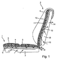
図1は、本発明による車両シートの第1の実施形態を示す。 FIG. 1 shows a first embodiment of a vehicle seat according to the present invention.
車両シートはシートクッション1及びバックレスト2から成る。 The vehicle seat includes a seat cushion 1 and a backrest 2.
シートクッション1と、又バックレスト2とは、本質的に、本発明による同じ層構造から構成される。 The seat cushion 1 and the backrest 2 are essentially composed of the same layer structure according to the invention.
この層構造は、フリースの積層体から構成される上部カバー3と、その下側に配置され、垂直の空気及び湿気を導く流路5を有する発泡体芯材4と、続いてその下側に配置され、ゴム製ニットからなる空気ガイド層6とから構成される。
This layer structure consists of a top cover 3 composed of a fleece laminate, a foam core 4 disposed below it and having a
層3、4及び6の組立体は、シートクッション1用のスプリング芯材7の上に配置される。カバー3は空気及び湿気の透過性があるので、暖かく湿った空気は、発泡体芯材4内の流路5を通ってゴム製ニット6の中に導かれる。シートクッション1の後端には、ゴム製ニット6の領域に流出開口8が設けられ、その開口8から暖かく湿った空気が流出できる。
The assembly of layers 3, 4 and 6 is arranged on a spring core 7 for the seat cushion 1. Since the cover 3 is permeable to air and moisture, warm and humid air is guided into the rubber knit 6 through the
暖かく湿った空気がこの流出開口8から流出すると、冷たく乾いた空気が周囲から吸引されてゴム製ニット6の中に流入する。このため、ゴム製ニット6は、スプリング芯材7に向かって空気透過性の表面を有している。 When warm and moist air flows out from the outflow opening 8, cold and dry air is sucked from the surroundings and flows into the rubber knit 6. For this reason, the rubber knit 6 has an air-permeable surface toward the spring core material 7.
同じ方式がバックレスト2の領域でも実施される。 The same method is also implemented in the area of the backrest 2.
バックレスト2は、同様に、発泡体芯材10の上に配置される空気及び湿気の透過性があるカバー9を含み、発泡体芯材10の内部には基本的に水平方向に流路11が設けられる。走行方向に見て発泡体芯材10の背後に、例えばゴム製ニットの形の空気ガイド層12が設けられる。ゴム製ニットはスプリング芯材13の上に支持される。バックレスト2の上端には、流出開口14が配置される。流入開口15は、バックレスト2の下部領域に、前記流出開口14から可能な限り最大の距離を取って設けられる。開口14及び15は、バックレスト2の背面伸張部分に開口している。暖かく湿った空気が、カバー9及び流路11を経由してゴム製ニット12内に流入すると、追加の冷たく乾いた空気が流入開口15を通して下方より吸引される。
Similarly, the backrest 2 includes a cover 9, which is disposed on the
図2は車両シートの第2の実施形態を示す。この車両シートにおいては、ゴム製ニット製の空気ガイド層17が、カバー16の直接下側に配置される。その下に、少なくとも1つの流入開口19を備えた発泡体芯材18が装着され、流入開口19は、発泡体芯材18に設けられるとともに、さらなる冷たく乾いた空気を吸引するために好ましくはシートクッション1の前部領域に配置され、かつ下向きに開口している。場合によっては、当該開口をシートクッションの外殻又はスプリング芯材の領域に設ける。
FIG. 2 shows a second embodiment of the vehicle seat. In this vehicle seat, a rubber knit
バックレスト2は、カバー20と、空気ガイド層21と、発泡体芯材22とから同様の方法で構成される。前記バックレストの背面に、流出開口23及び流入開口24を、「煙突効果」を作り出すのに十分な程度に互いに距離を置いて配置する。
The backrest 2 is composed of a
図3には、本発明による車両シート及びクッションの第3の実施形態を示す。この構造は、本質的に図2の実施形態と同じであるが、シートクッション1の発泡体芯材18を、多数の垂直の流路25と少なくとも1つの水平流路26とが貫通している点が異なる。
FIG. 3 shows a third embodiment of the vehicle seat and cushion according to the present invention. This structure is essentially the same as the embodiment of FIG. 2, but a number of
暖かく湿った空気の排気がシートクッション1の後端の流出開口8を通って流出することに基づく吸引効果によって、追加の冷たく乾いた空気が、スプリング芯材7の下面あるいはクッション外殻の下面から発泡体芯材18の垂直流路25を通して吸引されて、暖かく湿った空気と混合する。暖かく湿った空気は、ゴム製ニット17を通って水平流路26に流入した後、混合空気が流出開口14から流出する。
Due to the suction effect based on the exhaust of warm and humid air flowing out through the outflow opening 8 at the rear end of the seat cushion 1, additional cold and dry air is drawn from the lower surface of the spring core 7 or the lower surface of the cushion shell. It is drawn through the
バックレスト2の領域における流動条件も同様であり、追加の冷たく乾いた空気が、流入開口24から水平流路27に供給され、続いて、少なくとも1つの基本的に垂直に延びる流路28に供給された後、暖かく湿った空気の排気が流出開口23から流出し得る。
The flow conditions in the region of the backrest 2 are similar, with additional cold and dry air being supplied from the
1 シートクッション
2 バックレスト
3 シートクッションカバー
4 シートクッション発泡体芯材
5 発泡体芯材内の流路
6 シートクッション空気ガイド層/ゴム製ニット
7 スプリング芯材/クッション外殻
8 流出開口
9 バックレストカバー
10 バックレスト発泡体芯材
11 発泡体芯材内の流路
12 バックレスト空気ガイド層/ゴム製ニット
13 スプリング芯材
14 流出開口
15 流入開口
16 シートクッションカバー
17 シートクッション空気ガイド層
18 シートクッション発泡体芯材
19 流入開口
20 バックレストカバー
21 バックレスト空気ガイド層
22 バックレスト発泡体芯材
23 流出開口
24 流入開口
25 シートクッション垂直流路
26 シートクッション水平流路
27 バックレスト水平流路
28 バックレスト垂直流路
DESCRIPTION OF SYMBOLS 1 Seat cushion 2 Backrest 3 Seat cushion cover 4 Seat cushion
Claims (9)
前記流出開口(8、14、23)が、暖かく湿った空気を流出することによって乾燥した冷たい外気が自動的に前記空気ガイド層(6、12、17、21)に流入するように、前記空気ガイド層(6、12、17、21)に対して配置されることを特徴とするクッション。 An assembly comprising a layer having a cover (3, 9, 16, 20), a foam core (4, 10, 18, 22) and an air guide layer (6, 12, 17, 21) was provided. A cushion for a vehicle seat, wherein at least one outflow opening (8, 14, 23) is provided to remove warm and humid air,
The air flows so that the outflow openings (8, 14, 23) automatically flow into the air guide layers (6, 12, 17, 21) by the outflow of warm and humid air. Cushion, characterized in that it is arranged against the guide layer (6, 12, 17, 21).
Applications Claiming Priority (2)
| Application Number | Priority Date | Filing Date | Title |
|---|---|---|---|
| DE102005006060A DE102005006060A1 (en) | 2005-02-10 | 2005-02-10 | Vehicle seat and padding for this |
| PCT/EP2006/000540 WO2006084562A1 (en) | 2005-02-10 | 2006-01-21 | Vehicle seat and cushion therefor |
Publications (2)
| Publication Number | Publication Date |
|---|---|
| JP2008529621A true JP2008529621A (en) | 2008-08-07 |
| JP2008529621A5 JP2008529621A5 (en) | 2009-03-12 |
Family
ID=35884049
Family Applications (1)
| Application Number | Title | Priority Date | Filing Date |
|---|---|---|---|
| JP2007554460A Abandoned JP2008529621A (en) | 2005-02-10 | 2006-01-21 | Vehicle seat and cushion thereof |
Country Status (5)
| Country | Link |
|---|---|
| US (1) | US20080246325A1 (en) |
| EP (1) | EP1846262A1 (en) |
| JP (1) | JP2008529621A (en) |
| DE (1) | DE102005006060A1 (en) |
| WO (1) | WO2006084562A1 (en) |
Cited By (3)
| Publication number | Priority date | Publication date | Assignee | Title |
|---|---|---|---|---|
| JP2009247897A (en) * | 2008-04-08 | 2009-10-29 | Wet Automotive Syst Ag | Ventilation means |
| JP2014023677A (en) * | 2012-07-26 | 2014-02-06 | Tachi-S Co Ltd | Seat cushion for use in automobile seat |
| JP2014024426A (en) * | 2012-07-26 | 2014-02-06 | Tachi-S Co Ltd | Seat back to be used in automobile seat |
Families Citing this family (7)
| Publication number | Priority date | Publication date | Assignee | Title |
|---|---|---|---|---|
| DE102009031726A1 (en) | 2009-07-04 | 2011-01-05 | Daimler Ag | Air guidance layer for cushion of motor vehicle seat, has upper side and lower side provided with set of bars arranged to each other without cover, and closed bar contour closed within one plane and formed by bar arrangement |
| CN201752306U (en) * | 2010-07-13 | 2011-03-02 | 杨卫新 | Suction and exhaust type ventilation seat cushion conforming to human engineering |
| IT1402714B1 (en) * | 2010-10-28 | 2013-09-18 | Delphi Italia Automotive Systems S R L | AIR-CONDITIONED SEAT FOR A CAB OF A VEHICLE |
| DE202011109474U1 (en) | 2011-01-06 | 2012-04-16 | I.G. Bauerhin Gmbh | vehicle seat |
| DE102011121991B4 (en) * | 2011-12-22 | 2014-02-27 | Grammer Ag | Vehicle seat and method for manufacturing a vehicle seat cushion part |
| JP6763294B2 (en) * | 2016-12-21 | 2020-09-30 | トヨタ紡織株式会社 | Vehicle seat |
| DE102019116422B3 (en) | 2019-06-18 | 2020-08-06 | Dr. Ing. H.C. F. Porsche Aktiengesellschaft | Dehumidification arrangement for a vehicle seat and vehicle seat |
Family Cites Families (14)
| Publication number | Priority date | Publication date | Assignee | Title |
|---|---|---|---|---|
| US3550523A (en) * | 1969-05-12 | 1970-12-29 | Irving Segal | Seat construction for automotive air conditioning |
| DE3609095A1 (en) * | 1985-03-28 | 1986-10-09 | Keiper Recaro GmbH & Co KG, 5630 Remscheid | Vehicle seat |
| DE3722814A1 (en) * | 1987-07-10 | 1989-01-19 | Grammer Sitzsysteme Gmbh | Foam-backed article and process for the production thereof |
| DE3725146A1 (en) * | 1987-07-29 | 1989-02-09 | Bayerische Motoren Werke Ag | Seat, in particular for motor vehicles |
| DE4112631C1 (en) * | 1991-04-18 | 1992-04-30 | Keiper Recaro Gmbh & Co, 5630 Remscheid, De | Motor vehicle seat with moisture removal inset - incorporating air channel at rear of backrest with air dryer |
| DE19804100C1 (en) * | 1998-02-03 | 1999-05-12 | Daimler Chrysler Ag | Automobile seat with incorporated ventilation |
| DE19804284C2 (en) * | 1998-02-04 | 2002-03-14 | Daimler Chrysler Ag | vehicle seat |
| DE19846090C2 (en) * | 1998-10-07 | 2003-05-22 | Faurecia Autositze Gmbh & Co | Motor vehicle seat with ventilation device |
| DE19920062C2 (en) * | 1999-05-03 | 2003-11-06 | Daimler Chrysler Ag | vehicle seat |
| DE20002447U1 (en) * | 1999-09-21 | 2001-02-08 | Johnson Controls GmbH, 51399 Burscheid | Seat pads for vehicle seats |
| DE19954978C1 (en) * | 1999-11-16 | 2001-01-11 | Daimler Chrysler Ag | Seat squab for automobile passenger seat has perforated electric heating mat between actively ventilated cushion pad and pervious seat cushion covering |
| DE10049458A1 (en) * | 2000-10-06 | 2002-04-18 | Daimler Chrysler Ag | Upholstery for a vehicle seat |
| DE20112473U1 (en) * | 2001-07-28 | 2002-12-19 | Johnson Controls GmbH, 51399 Burscheid | Air-conditioned upholstery part for a vehicle seat |
| DE10243315B4 (en) * | 2002-09-18 | 2005-11-17 | Daimlerchrysler Ag | Upholstery for a vehicle seat |
-
2005
- 2005-02-10 DE DE102005006060A patent/DE102005006060A1/en not_active Withdrawn
-
2006
- 2006-01-21 EP EP06706347A patent/EP1846262A1/en not_active Withdrawn
- 2006-01-21 JP JP2007554460A patent/JP2008529621A/en not_active Abandoned
- 2006-01-21 US US11/884,046 patent/US20080246325A1/en not_active Abandoned
- 2006-01-21 WO PCT/EP2006/000540 patent/WO2006084562A1/en active Application Filing
Cited By (3)
| Publication number | Priority date | Publication date | Assignee | Title |
|---|---|---|---|---|
| JP2009247897A (en) * | 2008-04-08 | 2009-10-29 | Wet Automotive Syst Ag | Ventilation means |
| JP2014023677A (en) * | 2012-07-26 | 2014-02-06 | Tachi-S Co Ltd | Seat cushion for use in automobile seat |
| JP2014024426A (en) * | 2012-07-26 | 2014-02-06 | Tachi-S Co Ltd | Seat back to be used in automobile seat |
Also Published As
| Publication number | Publication date |
|---|---|
| WO2006084562A1 (en) | 2006-08-17 |
| EP1846262A1 (en) | 2007-10-24 |
| DE102005006060A1 (en) | 2006-08-24 |
| US20080246325A1 (en) | 2008-10-09 |
Similar Documents
| Publication | Publication Date | Title |
|---|---|---|
| JP2008529621A (en) | Vehicle seat and cushion thereof | |
| JP3236271B2 (en) | Vehicle seat | |
| JP4121500B2 (en) | Automotive seat cushion | |
| US6629725B1 (en) | Seat part for a vehicle seat | |
| JP3111316B2 (en) | Vehicle seat | |
| JP2007520288A (en) | Vehicle seat | |
| JP3586662B2 (en) | Actively breathable seat module for vehicle seats | |
| US6196627B1 (en) | Vehicle seat | |
| US5902014A (en) | Ventilated vehicle seat with a plurality of miniature ventilators | |
| JP2004520888A (en) | Portable ventilated seat | |
| JP2009524461A (en) | Automotive seat cushion | |
| ITRM990016A1 (en) | SEAT, IN PARTICULAR FOR VEHICLES. | |
| US7837270B2 (en) | Vehicle seat having a ventilation system | |
| CN202966037U (en) | Ventilating seat cushion and automobile seat | |
| JP2008529621A5 (en) | ||
| US20090127894A1 (en) | Vehicle Seat with a Ventilation Device | |
| CN103042961A (en) | Ventilative seat cushion and automobile seat | |
| KR101572676B1 (en) | Ventilating device of vehicles | |
| CN203142449U (en) | Ventilated chair cushion structure capable of eliminating VOC (Volatile Organic Compounds) | |
| CN202686035U (en) | Rear-mounted ventilating cushion of fan | |
| KR101501077B1 (en) | Device for seat lower ventilation of vehicle | |
| JP5855403B2 (en) | Air conditioning sheet | |
| JP4513363B2 (en) | Air-conditioning seat device | |
| DE202006016873U1 (en) | Vehicle seat, has backrest with contact surface provided with number of funnel shaped air nozzles, which are connected with one another by acrylic hoses, connected to suction manifold and remain open when seat is loaded | |
| JP5599361B2 (en) | Vehicle seat |
Legal Events
| Date | Code | Title | Description |
|---|---|---|---|
| A521 | Request for written amendment filed |
Free format text: JAPANESE INTERMEDIATE CODE: A523 Effective date: 20090120 |
|
| A621 | Written request for application examination |
Free format text: JAPANESE INTERMEDIATE CODE: A621 Effective date: 20090120 |
|
| A762 | Written abandonment of application |
Free format text: JAPANESE INTERMEDIATE CODE: A762 Effective date: 20090512 |