JP2008527806A - Night monitoring system and method - Google Patents
Night monitoring system and method Download PDFInfo
- Publication number
- JP2008527806A JP2008527806A JP2007549706A JP2007549706A JP2008527806A JP 2008527806 A JP2008527806 A JP 2008527806A JP 2007549706 A JP2007549706 A JP 2007549706A JP 2007549706 A JP2007549706 A JP 2007549706A JP 2008527806 A JP2008527806 A JP 2008527806A
- Authority
- JP
- Japan
- Prior art keywords
- camera
- image
- background image
- live video
- illuminator
- Prior art date
- Legal status (The legal status is an assumption and is not a legal conclusion. Google has not performed a legal analysis and makes no representation as to the accuracy of the status listed.)
- Pending
Links
Images


Classifications
-
- G—PHYSICS
- G08—SIGNALLING
- G08B—SIGNALLING OR CALLING SYSTEMS; ORDER TELEGRAPHS; ALARM SYSTEMS
- G08B13/00—Burglar, theft or intruder alarms
- G08B13/18—Actuation by interference with heat, light, or radiation of shorter wavelength; Actuation by intruding sources of heat, light, or radiation of shorter wavelength
- G08B13/189—Actuation by interference with heat, light, or radiation of shorter wavelength; Actuation by intruding sources of heat, light, or radiation of shorter wavelength using passive radiation detection systems
- G08B13/194—Actuation by interference with heat, light, or radiation of shorter wavelength; Actuation by intruding sources of heat, light, or radiation of shorter wavelength using passive radiation detection systems using image scanning and comparing systems
- G08B13/196—Actuation by interference with heat, light, or radiation of shorter wavelength; Actuation by intruding sources of heat, light, or radiation of shorter wavelength using passive radiation detection systems using image scanning and comparing systems using television cameras
- G08B13/19678—User interface
- G08B13/19689—Remote control of cameras, e.g. remote orientation or image zooming control for a PTZ camera
-
- H—ELECTRICITY
- H04—ELECTRIC COMMUNICATION TECHNIQUE
- H04N—PICTORIAL COMMUNICATION, e.g. TELEVISION
- H04N7/00—Television systems
- H04N7/18—Closed-circuit television [CCTV] systems, i.e. systems in which the video signal is not broadcast
-
- G—PHYSICS
- G08—SIGNALLING
- G08B—SIGNALLING OR CALLING SYSTEMS; ORDER TELEGRAPHS; ALARM SYSTEMS
- G08B13/00—Burglar, theft or intruder alarms
- G08B13/18—Actuation by interference with heat, light, or radiation of shorter wavelength; Actuation by intruding sources of heat, light, or radiation of shorter wavelength
- G08B13/189—Actuation by interference with heat, light, or radiation of shorter wavelength; Actuation by intruding sources of heat, light, or radiation of shorter wavelength using passive radiation detection systems
- G08B13/194—Actuation by interference with heat, light, or radiation of shorter wavelength; Actuation by intruding sources of heat, light, or radiation of shorter wavelength using passive radiation detection systems using image scanning and comparing systems
- G08B13/196—Actuation by interference with heat, light, or radiation of shorter wavelength; Actuation by intruding sources of heat, light, or radiation of shorter wavelength using passive radiation detection systems using image scanning and comparing systems using television cameras
- G08B13/19602—Image analysis to detect motion of the intruder, e.g. by frame subtraction
- G08B13/19606—Discriminating between target movement or movement in an area of interest and other non-signicative movements, e.g. target movements induced by camera shake or movements of pets, falling leaves, rotating fan
-
- G—PHYSICS
- G08—SIGNALLING
- G08B—SIGNALLING OR CALLING SYSTEMS; ORDER TELEGRAPHS; ALARM SYSTEMS
- G08B13/00—Burglar, theft or intruder alarms
- G08B13/18—Actuation by interference with heat, light, or radiation of shorter wavelength; Actuation by intruding sources of heat, light, or radiation of shorter wavelength
- G08B13/189—Actuation by interference with heat, light, or radiation of shorter wavelength; Actuation by intruding sources of heat, light, or radiation of shorter wavelength using passive radiation detection systems
- G08B13/194—Actuation by interference with heat, light, or radiation of shorter wavelength; Actuation by intruding sources of heat, light, or radiation of shorter wavelength using passive radiation detection systems using image scanning and comparing systems
- G08B13/196—Actuation by interference with heat, light, or radiation of shorter wavelength; Actuation by intruding sources of heat, light, or radiation of shorter wavelength using passive radiation detection systems using image scanning and comparing systems using television cameras
- G08B13/19678—User interface
- G08B13/19682—Graphic User Interface [GUI] presenting system data to the user, e.g. information on a screen helping a user interacting with an alarm system
-
- G—PHYSICS
- G08—SIGNALLING
- G08B—SIGNALLING OR CALLING SYSTEMS; ORDER TELEGRAPHS; ALARM SYSTEMS
- G08B13/00—Burglar, theft or intruder alarms
- G08B13/18—Actuation by interference with heat, light, or radiation of shorter wavelength; Actuation by intruding sources of heat, light, or radiation of shorter wavelength
- G08B13/189—Actuation by interference with heat, light, or radiation of shorter wavelength; Actuation by intruding sources of heat, light, or radiation of shorter wavelength using passive radiation detection systems
- G08B13/194—Actuation by interference with heat, light, or radiation of shorter wavelength; Actuation by intruding sources of heat, light, or radiation of shorter wavelength using passive radiation detection systems using image scanning and comparing systems
- G08B13/196—Actuation by interference with heat, light, or radiation of shorter wavelength; Actuation by intruding sources of heat, light, or radiation of shorter wavelength using passive radiation detection systems using image scanning and comparing systems using television cameras
- G08B13/19695—Arrangements wherein non-video detectors start video recording or forwarding but do not generate an alarm themselves
-
- H—ELECTRICITY
- H04—ELECTRIC COMMUNICATION TECHNIQUE
- H04N—PICTORIAL COMMUNICATION, e.g. TELEVISION
- H04N23/00—Cameras or camera modules comprising electronic image sensors; Control thereof
- H04N23/60—Control of cameras or camera modules
- H04N23/62—Control of parameters via user interfaces
-
- H—ELECTRICITY
- H04—ELECTRIC COMMUNICATION TECHNIQUE
- H04N—PICTORIAL COMMUNICATION, e.g. TELEVISION
- H04N23/00—Cameras or camera modules comprising electronic image sensors; Control thereof
- H04N23/60—Control of cameras or camera modules
- H04N23/63—Control of cameras or camera modules by using electronic viewfinders
- H04N23/631—Graphical user interfaces [GUI] specially adapted for controlling image capture or setting capture parameters
- H04N23/632—Graphical user interfaces [GUI] specially adapted for controlling image capture or setting capture parameters for displaying or modifying preview images prior to image capturing, e.g. variety of image resolutions or capturing parameters
-
- H—ELECTRICITY
- H04—ELECTRIC COMMUNICATION TECHNIQUE
- H04N—PICTORIAL COMMUNICATION, e.g. TELEVISION
- H04N23/00—Cameras or camera modules comprising electronic image sensors; Control thereof
- H04N23/60—Control of cameras or camera modules
- H04N23/63—Control of cameras or camera modules by using electronic viewfinders
- H04N23/633—Control of cameras or camera modules by using electronic viewfinders for displaying additional information relating to control or operation of the camera
- H04N23/635—Region indicators; Field of view indicators
-
- H—ELECTRICITY
- H04—ELECTRIC COMMUNICATION TECHNIQUE
- H04N—PICTORIAL COMMUNICATION, e.g. TELEVISION
- H04N23/00—Cameras or camera modules comprising electronic image sensors; Control thereof
- H04N23/60—Control of cameras or camera modules
- H04N23/66—Remote control of cameras or camera parts, e.g. by remote control devices
- H04N23/661—Transmitting camera control signals through networks, e.g. control via the Internet
-
- H—ELECTRICITY
- H04—ELECTRIC COMMUNICATION TECHNIQUE
- H04N—PICTORIAL COMMUNICATION, e.g. TELEVISION
- H04N23/00—Cameras or camera modules comprising electronic image sensors; Control thereof
- H04N23/60—Control of cameras or camera modules
- H04N23/695—Control of camera direction for changing a field of view, e.g. pan, tilt or based on tracking of objects
-
- H—ELECTRICITY
- H04—ELECTRIC COMMUNICATION TECHNIQUE
- H04N—PICTORIAL COMMUNICATION, e.g. TELEVISION
- H04N23/00—Cameras or camera modules comprising electronic image sensors; Control thereof
- H04N23/60—Control of cameras or camera modules
- H04N23/698—Control of cameras or camera modules for achieving an enlarged field of view, e.g. panoramic image capture
-
- H—ELECTRICITY
- H04—ELECTRIC COMMUNICATION TECHNIQUE
- H04N—PICTORIAL COMMUNICATION, e.g. TELEVISION
- H04N5/00—Details of television systems
- H04N5/222—Studio circuitry; Studio devices; Studio equipment
- H04N5/262—Studio circuits, e.g. for mixing, switching-over, change of character of image, other special effects ; Cameras specially adapted for the electronic generation of special effects
- H04N5/272—Means for inserting a foreground image in a background image, i.e. inlay, outlay
- H04N5/2723—Insertion of virtual advertisement; Replacing advertisements physical present in the scene by virtual advertisement
-
- H—ELECTRICITY
- H04—ELECTRIC COMMUNICATION TECHNIQUE
- H04N—PICTORIAL COMMUNICATION, e.g. TELEVISION
- H04N5/00—Details of television systems
- H04N5/30—Transforming light or analogous information into electric information
- H04N5/33—Transforming infrared radiation
Abstract
監視の方法およびシステムが説明される。説明される、カメラを有する監視システム内で使用するための一方法は、カメラの対象領域の背景画像を生成すること、対象領域内にあるカメラの現在視野のライブビデオ画像を受け取ること、および背景画像内でライブビデオ画像の位置を相関させることを含む。
【選択図】図1A monitoring method and system is described. One method for use in a surveillance system having a camera as described is to generate a background image of a target area of the camera, receive a live video image of the current field of view of the camera within the target area, and background Including correlating the position of the live video image within the image.
[Selection] Figure 1
Description
関連出願
[0001]
本発明は、参照によりその全部が本明細書に組み込まれる、2005年1月3日に出願した、「監視カメラに基づいたアクティブ照明の夜間性能の向上についてのシステム及び方法(SYSTEM AND A METHOD FOR IMPROVING NIGHT TIME PERFORMANCE OF ACTIVE ILLUMINATION BASED SURVEILLANCE CAMERAS)」という名称の米国仮特許出願第60/640244号の優先権を主張するものである。
Related Application [0001]
The present invention was filed on Jan. 3, 2005, which is hereby incorporated by reference in its entirety, “SYSTEM AND A METHOD FOR. US Provisional Patent Application No. 60/640244 entitled “IMPROVING NIGHT TIME PERFORMANCE OF ACTIVE ILLUMINATION BASED SURVEILLANCE CAMERAS)”.
技術分野
[0002]
本発明は、一般に、監視システムに関し、より詳細には、本発明の実施形態は暗視監視システムのシステムおよび方法に関する。
Technical field [0002]
The present invention relates generally to surveillance systems, and more particularly, embodiments of the present invention relate to systems and methods for night vision surveillance systems.
背景技術
[0003]
赤外線照射器を使用する暗視カメラは、高倍率を提供し得るが、この高倍率は、必然的に、狭い瞬間視野をもたらす。また、狭い視野は、所与の距離において、照射器のビームを、ある一定の角度を超えて拡散させると、有用な画像を生成するには不十分なビーム強度が必然的にもたらされることによるものである。この視野制限は、特に、カバーする必要のある領域が広く、複雑であるとき、または瞬間暗視視界の情報内容が低いときには、かかる監視カメラのユーザが監視対象領域内で方向定位するのを困難にする。
Background art [0003]
Night vision cameras using infrared illuminators can provide high magnification, but this high magnification necessarily results in a narrow instantaneous field of view. Also, the narrow field of view is that, at a given distance, diffusing the illuminator beam beyond a certain angle necessarily results in insufficient beam intensity to produce a useful image. Is. This visual field limitation makes it difficult for the user of such a surveillance camera to orient in the surveillance area, especially when the area that needs to be covered is large and complex, or when the information content of the instantaneous night vision field is low. To.
[0004]
この限界を克服するのに使用され得る一方法が、現在視野を位置決めするのに役立ち得る目立った目標物を見つけるために、対象領域を系統的に走査するものである。監視作業の性質上、かかるサーチ手順は、緊急時に貴重な時間を使い果たすことになり得るため、一般に実際的はでない。これによって派生する、監視カメラの対象領域を定義する典型的な角度セクタをカバーするために監視カメラが必要とする長い走査時間が問題となり得る。
[0004]
One method that can be used to overcome this limitation is to systematically scan the region of interest to find prominent targets that can help position the current field of view. Due to the nature of monitoring work, such a search procedure is generally not practical because it can use up valuable time in an emergency. This can lead to problems with the long scan time required by the surveillance camera to cover the typical angular sector that defines the area of interest of the surveillance camera.
[0005]
暗視システムの中には、レーザ赤外線照射器を利用するものもある。これらのシステムの多くは、ゲート式撮像技術を利用して、主要な雑音機構とみなされる大気による後方散乱を克服する。ゲート式撮像技術の使用は、高価な撮像器と、レーザパルスと撮像器の複雑な同期を必要とする。加えて、ゲート式撮像に基づく暗視システムは、撮像器の視野内の強烈な光源による飽和の影響を受けやすい。また、従来のレーザ照射暗視システムの使用は、目の安全の問題を提示する可能性もあり、用途によっては、レーザ安全管理者が暗視システムの現場にいることを必要とし得る。
[0005]
Some night vision systems use laser infrared irradiators. Many of these systems utilize gated imaging technology to overcome atmospheric backscatter, which is considered the primary noise mechanism. The use of gated imaging techniques requires expensive imagers and complex synchronization of laser pulses and imagers. In addition, night vision systems based on gated imaging are susceptible to saturation due to intense light sources in the field of view of the imager. Also, the use of conventional laser-illuminated night vision systems can present eye safety issues and, depending on the application, may require that a laser safety manager be present at the night vision system site.
[0006]
他の暗視システムには、LED電球によって生成されるアクティブ赤外線照明を、その投射光を拾うように設定されたカメラと共に利用するものもある。これらのシステムは、短距離でのみ使用可能な画像を提供し、電球は比較的短命であり、システムに保守と運用のコストが増える。加えて、これらのシステムもやはり撮像器の視野内の強烈な光源による飽和の影響を受けやすい。
[0006]
Other night vision systems utilize active infrared illumination generated by LED bulbs with a camera set to pick up the projected light. These systems provide images that can only be used at short distances, bulbs are relatively short-lived, increasing the maintenance and operating costs of the system. In addition, these systems are also susceptible to saturation by intense light sources in the field of view of the imager.
[0007]
別の暗視システムは、高感度CCDカメラによって捕捉される周辺光(星明かりや月明かりなど)を利用するICCD(Intensified CCD)構成を使用する。これらのシステムもまた、動作距離が短く、曇った夜や月のない夜には機能しない。加えて、これらのシステムは、撮像器の視野内の強烈な光源による飽和の影響を受けやすい。
[0007]
Another night vision system uses an ICCD (Intensified CCD) configuration that utilizes ambient light (such as starlight or moonlight) captured by a high sensitivity CCD camera. These systems also have short working distances and do not work on cloudy nights or moonless nights. In addition, these systems are susceptible to saturation due to intense light sources in the field of view of the imager.
[0008]
最も一般的な暗視システムは、熱撮像に基づくものであり、対象の熱を使って結果の画像が生成される。操作者が訓練を積めば、結果画像を検出に使用し得るが、文字も画像詳細も見えないため、正確な識別には使用できない。加えて、非冷却式熱システムは距離が短く、他方冷却式システムは、距離はより長いが、非常に高価である。最後に、熱システムにズーム機能を追加するのは、専用レンズを使用する必要があるため高くつく。このため、多くの熱システムは、固定焦点距離である。
[0008]
The most common night vision system is based on thermal imaging, where the heat of interest is used to generate the resulting image. If the operator is trained, the resulting image can be used for detection, but neither text nor image details can be seen and therefore cannot be used for accurate identification. In addition, uncooled thermal systems are short in distance, while cooled systems are longer but very expensive. Finally, adding a zoom function to a thermal system is expensive because it requires the use of a dedicated lens. For this reason, many thermal systems have a fixed focal length.
発明の概要
[0009]
本発明の実施形態は、現在視野を含む監視対象領域の広い視界を提供するシステムおよび方法を含む、夜間監視のシステムおよび方法を提供する。このシステムおよび方法は、ユーザが、現在視野がどこに位置決めされているか即座に理解し、適切な空間方向定位を獲得し、脅威検出の場合には、誘導される適切な措置を講じることを可能にし得る。また、このシステムおよび方法は、監視カメラの走査対象セクタ内の所与の地点の再訪時間はもとより、対象領域走査時間を短縮することもできる。一実施形態において、カメラを有する監視システム内で使用するための方法は、カメラの対象領域の背景画像を生成すること、対象領域内にある、カメラの現在視野のライブビデオ画像を受け取ること、および背景画像内でライブビデオ画像の位置を相関させることを含む。ライブビデオ画像は、背景画像上にライブビデオ画像の位置標識を表示することによって背景画像と関連付けられてもよく、ライブビデオ画像を、背景画像上でその相対的な位置に融合させることによって関連付けられても良い。
SUMMARY OF THE INVENTION [0009]
Embodiments of the present invention provide night-time monitoring systems and methods, including systems and methods that provide a wide view of the monitored area, including the current field of view. This system and method allows the user to immediately understand where the current field of view is located, to obtain the proper spatial orientation, and in the case of threat detection, take appropriate action to be guided. obtain. The system and method can also reduce the target area scan time as well as the revisit time for a given point in the surveillance camera's scan target sector. In one embodiment, a method for use in a surveillance system having a camera generates a background image of a target area of the camera, receives a live video image of a current view of the camera within the target area, and Including correlating the position of the live video image within the background image. A live video image may be associated with a background image by displaying a live video image position indicator on the background image, and associated by fusing the live video image to its relative position on the background image. May be.
[0010]
別の実施形態において、暗視監視システムは、対象領域を有するカメラと、照射ビームを生成することのできる照射器と、対象領域の背景画像を生成し、照射ビームを使ってカメラによって取り込まれる、対象領域内にあるカメラの現在視野のライブビデオ画像を受け取り、背景画像内でライブビデオ画像の位置を相関させることのできるコンピュータとを備える。
[0010]
In another embodiment, the night vision monitoring system includes a camera having a region of interest, an illuminator capable of generating an illumination beam, a background image of the region of interest, and captured by the camera using the illumination beam. A computer capable of receiving a live video image of the current field of view of the camera within the region of interest and correlating the position of the live video image in the background image.
[0011]
別の実施形態において、少なくとも1台のカメラを使用する監視方法は、カメラの対象領域の背景画像を生成すること、対象領域内の少なくとも1つの目標の位置に対応する目標位置情報に基づいて対象領域を走査すること、少なくとも1つの目標を含む、対象領域内にあるカメラの現在視野のライブビデオ画像を受け取ること、および背景画像内でライブビデオ画像の位置を相関させることを含む。
[0011]
In another embodiment, a monitoring method using at least one camera generates a background image of a target area of the camera, and targets based on target position information corresponding to the position of at least one target in the target area. Scanning the area, receiving a live video image of the current field of view of the camera within the area of interest, including at least one target, and correlating the position of the live video image in the background image.
[0012]
別の実施形態において、暗視監視システムは、対象領域を有するカメラと、照射ビームを生成することのできる赤外線(IR)照射器であり、視差を生じるようにカメラから分離されている照射器と、カメラと照射器を制御することのできるコンピュータとを備える。また、システムは、照射器に近すぎる対象の有無を検出し、照射ビームを遮断することのできる安全モジュールを含んでいてもよい。
[0012]
In another embodiment, a night vision monitoring system includes a camera having a region of interest, an infrared (IR) illuminator capable of generating an illumination beam, and an illuminator separated from the camera to produce a parallax. And a computer that can control the irradiator. The system may also include a safety module that can detect the presence of an object that is too close to the illuminator and block the illumination beam.
[0013]
これらの例示的実施形態は、本発明を限定し、または定義するためではなく、本発明の理解に役立つ例を提供するために示すものである。例示的実施形態については、以下の詳細な説明で論じ、そこで本発明の詳細な説明を行う。本発明の様々な実施形態によって提供される利点は、本明細書をよく読めばさらに理解されよう。
[0013]
These exemplary embodiments are presented not to limit or define the invention, but to provide examples to help understand the invention. Exemplary embodiments are discussed in the detailed description which follows, which provides a detailed description of the invention. The advantages provided by the various embodiments of the present invention will be further understood upon reading this specification.
本発明の上記その他の特徴、態様および利点は、以下の詳細な説明を、添付の図面を参照して読めばよりよく理解されるものである。 These and other features, aspects and advantages of the present invention will become better understood when the following detailed description is read with reference to the accompanying drawings, in which:
詳細な説明
[0015]
本発明の実施形態は、夜間監視のシステムおよび方法を提供する。本発明の複数の実施形態がある。導入例として、本発明の1つの例示的実施形態は、ズーム視準レンズを備えるIRレーザ照射器、およびビデオカメラとズームレンズからなる撮像器を利用する夜間監視システムを提供する。照射器と撮像器の光軸は、大気による後方散乱を低減するために、視差を生じるように空間的に分離されている。レーザ照射器からの照射ビームは、視野全体にわたって光を均一に分散するように形成され得る。照射器内のコリメータの焦点距離は、カメラの焦点距離と一緒に変化するように作られていてもよく、これらの焦点距離が相互に独立に動くこともできる。また、システムは、対象が照射器に近すぎるときにこれを検出することができ、レーザ光源を遮断することができる安全機構または回路を含んでいてもよい。
Detailed Description [0015]
Embodiments of the present invention provide night-time monitoring systems and methods. There are multiple embodiments of the present invention. As an introductory example, one exemplary embodiment of the present invention provides an IR laser illuminator with a zoom collimating lens and a nighttime surveillance system that utilizes an imager consisting of a video camera and a zoom lens. The optical axes of the irradiator and the imager are spatially separated to produce parallax in order to reduce backscattering by the atmosphere. The illumination beam from the laser irradiator can be formed to evenly distribute the light throughout the field of view. The focal length of the collimator in the illuminator may be made to change with the focal length of the camera, and these focal lengths can also move independently of each other. The system may also include a safety mechanism or circuit that can detect when the subject is too close to the illuminator and can shut off the laser light source.
[0016]
システムは、カメラの対象領域のパノラマ背景画像を生成し、この背景画像と、IRレーザ照射器を使ってカメラによって取り込まれるライブビデオ画像を相関させる。システムは、ユーザに、ライブビデオ画像が対象領域内のどこに配置されているか明確に指示するために、背景画像と相関させたライブビデオ画像を表示し得る。システムは、ライブ夜間ビデオ画像を取り込むために、対象領域をインテリジェントに走査し得る。
[0016]
The system generates a panoramic background image of the target area of the camera and correlates this background image with a live video image captured by the camera using an IR laser illuminator. The system may display the live video image correlated with the background image to clearly indicate to the user where the live video image is located within the region of interest. The system can intelligently scan the area of interest to capture live night video images.
システムアーキテクチャ
[0017]
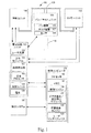
本発明による様々なシステムが構築され得る。次に図面を参照する。これらの図では、類似の要素を類似の番号で示す。図1は、本発明の一実施形態の実施のための例示的環境を示すブロック図である。図1に示すシステム100は、カメラユニット102と、パン/チルトユニット104と、照射ユニット106と、電子回路ユニット120と、制御コンピュータ150を含む。また、システム100は、熱検出システム、レーダ、フェンスシステムなどの目標検出システム160も含み得る。
System architecture [0017]
Various systems according to the present invention can be constructed. Reference is now made to the drawings. In these figures, similar elements are indicated by similar numbers. FIG. 1 is a block diagram illustrating an exemplary environment for implementation of an embodiment of the present invention. A
[0018]
パン/チルトユニット104は、ポール、スタンド、三脚、壁などといった構造110に取り付けられ得る。パン/チルトユニット104にアダプタブリッジ108を結合することができ、このアダプタブリッジ108は、カメラユニット102と照射ユニット106に接続され、これらを支持することができる。パン/チルトユニット104は、水平方向に動くことのできるパン機構105と、垂直方向に動くことのできるチルト機構107を含み得る。パン/チルトユニット104は、パン機構105とチルト機構107に、幅広いパノラマをカバーするように照射ユニット106とカメラユニット102を移動させる電子回路板120からの制御信号を受け取ることができる。また、パン/チルトユニット104は、パン/チルトユニット108の位置(パン角度とチルト角度)、よって、カメラユニット102と照射ユニット106の位置を指示する位置信号を提供するセンサ109も含み得る。別の実施形態では、パン/チルトユニット108を、可動式の、または不安定な台の上で使用するためにジャイロ安定機によって安定させる。
[0018]
The pan /
[0019]
別の実施形態では、システム100は、パン/チルトユニットを含まなくてもよく、カメラユニット102と照射ユニット106は固定されていてもよい。別の実施形態では、カメラユニット102と照射ユニット106は、別の場所にあり、別々のパンユニットとチルトユニットに取り付けられていてもよい。一実施形態では、カメラユニット102と照射ユニット106は、少なくとも6メートルの高さに取り付けられる。
[0019]
In another embodiment, the
[0020]
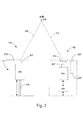
図2に示すように、照射ユニット106はアクティブ照射器211を収容するハウジング210を含み、照射器211は、光ファイバアダプタ212とズームコリメータ204を含む。また、照射器211は、図1に示す電子回路ユニット120内のレーザ高原122などの光源も含む。当分野の技術者に知られている他の適切な光源も使用され得る。光ファイバアダプタ212は、(以下で説明するように)電子回路ユニット120内のレーザ光源122からIRレーザ照射ビームを受け取る。一実施形態では、光ファイバアダプタ212は、円形の光ファイバケーブルである。ズームコリメータ204は、IRレーザ照射ビームを目標206に当て、制御するように動作する1つまたは複数の視準レンズ205を含み得る。ズームコリメータ204は、(以下で説明するように)電子回路ユニット102からズーム、フォーカスなどの制御信号を受け取ることができる。
[0020]
As shown in FIG. 2, the
[0021]
カメラユニット102は、ズームレンズ付きカメラ202、カメラインターフェースカード226、機械式照準機構224、およびスペクトルフィルタ機構222を囲い込むハウジング220を含み得る。一実施形態では、カメラ202は、例えば、CBC社製Computarレンズを備えるパナソニック社製CCDカメラなどである。
[0021]
The
[0022]
機械式照準機構224は、IRレーザ照射ビームの光軸230とカメラ202の光軸232を目標206に同時に整合させるのに使用され得る。カメラインターフェース226は、(以下で説明するように)電子回路ユニット120から、ズーム、フォーカス、ゲイン、シャッタなどの制御信号を受け取り、これらの制御信号をカメラ202に中継することができる。また、カメラインターフェース226は、カメラ202からビデオ画像信号を受け取り、これらのビデオ画像信号を電子回路ユニット120に送ることもできる。
[0022]
A mechanical aiming
[0023]
カメラ202とコリメータ204の焦点距離は、ロックする、すなわち、一致して変化させることもでき、独立に変化させることもできる。例えば、一実施形態では、制御コンピュータ150は、カメラ202のズーム設定とフォーカス設定を使用し、これらのパラメータをコリメータ204のズーム設定とフォーカス設定に変換して、2つの視野が同じサイズになるようにする。このようにして、カメラ202のズーム設定とフォーカス設定の変更が、コリメータ204での同様の変更を生じることになる。
[0023]
The focal lengths of the
[0024]
スペクトルフィルタ機構222は、夜間、あるいはそれ例外の光の全く、またはほとんどないときに、IRレーザ照射ビームを使用するカメラ202でビデオを取り込むのに使用され得る。スペクトルフィルタ機構222は、少なくとも1つの狭帯域幅またはカットオフフィルタと、運動機構を含み得る。狭帯域幅フィルタは、レーザ波長を伝え、他の光帯域を排除する。例えば、910nmレーザが使用される場合、900から920nmの波長帯域を有するフィルタが使用され得る。別の実施形態では、900nm以上の波長を有する光を伝え、900nmより低い波長を有する光を排除するカットオフフィルタが使用され得る。狭帯域幅フィルタを使用すれば、システムは、カメラの視野内の可能な全ダイナミックレンジの光に対処することができる。例えば、狭帯域幅フィルタがあれば、システムは、真っ暗な領域や近くの街路灯を、強い光によって飽和されずに見ることができる。運動機構は、夜間モードにあるとき、または、そうでなく、レーザ照射器を使用するときに、カメラレンズ207前の所定の位置にフィルタを移動させるのに使用される。一実施形態では、システム100は、昼間システムと夜間システムとして動作するように構成される。
[0024]
[0025]
一実施形態では、カメラ202とコリメータ204は、IR照射夜間システムでの雑音の主要原因とみなされる、短距離における大気中のエアロゾルから発する後方散乱を低減する視差を生じるように間隔を置いて配置される。短距離の後方散乱に起因する雑音は、長距離における後方散乱に起因する雑音よりも強い。視差を生じるように照射器をカメラから分離することによって、近距離の後方散乱が回避され、または低減され得る。例えば、カメラ202とコリメータ204を0.5メートル離すことができ、これは、レーザ照射ビーム230を使用するカメラ202で、カメラ202とコリメータ204から20メートル離れた対象の、後方散乱がほとんど、または全くない画像を取り込むことを可能にする。
[0025]
In one embodiment,
[0026]
一実施形態では、カメラユニット102と照射ユニット106は、単一のポールまたは三脚上に、カメラユニット102と照射ユニット106が相互に垂直になるように取り付けられる。例えば、照射ユニット106は、カメラユニット102の上部に取り付けられていてもよい。別の実施形態では、照射ユニット106とカメラユニット102は、別々のポールまたは三脚の上に取り付けられる。このようにして、大気による後方散乱は、完全に、またはほぼ完全に除去される。この実施形態では、照射ユニット106とカメラユニット102が、それぞれ、パン/チルトユニットを有していてもよく、これらのパン/チルトユニットは、相互に連動し合ってもよい。別の実施形態では、後方散乱を低減するために、制御コンピュータが画像処理技術を使って、画像のコントラストをデジタル式に伸張させることができる。
[0026]
In one embodiment, the
[0027]
レーザ光源を使用する照射器211は、1000メートル以上の動作範囲を可能にする輝度レベルの能力があるものとすることができる。コリメータ204は、レーザ照射ビームの拡散を、カメラの視野に対応して容易に変更させることができる。大部分の従来方式の夜間監視システムは、LEDまたは電球ベースの照射器を使用する。かかる照射器は、一般に、その輝度に限界があるために範囲が非常に限られており(最大150〜200m)、ビームの拡散角度とカメラの視野の同期的変更に対応することができない。
[0027]
The
[0028]
一実施形態では、照射レーザビームは、レーザビームの光が、そのレーザビーム全体にわたって均一に拡散するように形成される。例えば、光ファイバアダプタ212は、照射ビーム全体にわたる光の均一な分布を作り出すことができる。また、光ファイバアダプタ212は、円形であって、その外半径において強度の急激な降下を有する照射ビームを生じるようにも作用し得る。照射ビームの均一な光の拡散と鋭いエッジは、LEDまたは電球によって通常作られる照射ビームの不均一な光の拡散と緩やかなエッジとは対照的である。照射ビームのサイズは、コリメータレンズ205の焦点距離を制御することによって決定され得る。
[0028]
In one embodiment, the irradiating laser beam is formed such that the light of the laser beam diffuses uniformly throughout the laser beam. For example, the
[0029]
図1に戻って、カメラ202によって取り込まれるビデオ画像データは、カメラユニット102から電子回路ユニット120に送られる。次いで、電子回路ユニット120は、ビデオ画像データを制御コンピュータ150に転送する。制御コンピュータ150は、メモリ154などのコンピュータ可読媒体に結合されたプロセッサ152を含み得る。プロセッサ152は、以下で述べるように、カリフォルニア州サンタクララのインテル社製プロセッサや、イリノイ州ショウンバーグのモトローラ社製プロセッサなど、いくつかのコンピュータプロセッサのいずれかとすることができる。かかるプロセッサには、マイクロプロセッサ、ASIC、および状態機械も含まれ得る。かかるプロセッサは、コンピュータ可読媒体を含み、またはコンピュータ可読媒体と通信状態にあってもよく、コンピュータ可読媒体は、プロセッサによって実行されるとプロセッサに処置を実行させるプログラムコードまたは命令を格納する。コンピュータ可読媒体の実施形態には、それだけに限らないが、プロセッサにコンピュータ可読命令を提供することのできる、電子、光、磁気、その他の記憶装置または伝送装置が含まれる。他の適切な媒体の例には、それだけに限らないが、フロッピー(登録商標)ディスク、CD−ROM、DVD、磁気ディスク、メモリチップ、ROM、RAM、ASIC、構成済みプロセッサ、光媒体、磁気テープ媒体、またはコンピュータプロセッサが命令を読み出すことのできる他の任意の適切な媒体が含まれる。また、有線と無線両方の、ルータ、専用または公衆ネットワーク、あるいは他の伝送装置またはチャネルを含む、様々な他の形のコンピュータ可読媒体が、コンピュータにプログラムコードまたは命令を送信し、または搬送してもよい。命令は、例えば、C、C++、C#、Visual Basic、Java(登録商標)、Python、Perl、Java(登録商標)Scriptなどを含む、任意のコンピュータプログラミング言語のプログラムコードを含んでいてもよい。
[0029]
Returning to FIG. 1, the video image data captured by the
[0030]
制御コンピュータ150は、Microsoft(登録商標)Windows(登録商標)やLinuxなど、任意のオペレーティングシステム上で動作し得る。制御コンピュータの例が、パーソナルコンピュータ、サーバ機器、情報端末、携帯情報端末、移動電話機、デジタルタブレット、ラップトップコンピュータ、インターネット家電、その他のプロセッサベースの機器などである。一般に、制御コンピュータ150は、1つまたは複数のアプリケーションプログラムと対話する任意の適切な種類のプロセッサベースのプラットフォームとすることができる。制御コンピュータ150は、インターネットなどのネットワーク(不図示)に接続されていてもよく、有線または無線接続を介して電子回路ユニット120と検出システム160に直接接続されていてもよく、あるいは、有線または無線のネットワークを介して電子回路ユニット120と検出システム160に接続されていてもよい。制御コンピュータは、キーボード、マウス、ディスプレイ、記憶装置といった入出力機器を含んでいてもよい。
[0030]
The
[0031]
制御コンピュータ上で走り、メモリ154に記憶されるプログラムコードには、制御エンジン156、背景画像エンジン158、ビデオ動き/変化検出モジュール157、ユーザインターフェースアプリケーション159が含まれる。制御エンジン156は、レーザ光源122、コリメータ204、およびカメラ202を制御するのに使用され得る制御信号を計算し、電子回路ユニット120に送ることができる。背景画像エンジン158は、カメラユニット102から画像データを受け取って背景画像を生成し、ライブビデオ画像と背景画像を相関させることができる。ビデオ変化/動き検出モジュール157は、カメラ視野内の動く対象を検出し、隔離することのできる動き検出アルゴリズムと、例えば、空港内の放置物や美術館における紛失絵画など、所与の視野内の新しい、または欠けている対象を識別することのできる変化検出アルゴリズムを含む。
[0031]
Program code running on the control computer and stored in
[0032]
ユーザインターフェースアプリケーション159は、表示装置上に、ユーザがシステムと対話できるようにするユーザインターフェースを提示する。図3に、ユーザインターフェース300の例を示す。
[0032]
[0033]
電子回路ユニット120は、レーザ光源122と、安全モジュール128と、制御ユニット124を含み得る。レーザ光源122は、光ファイバ134を介して照射ユニット106にレーザビームを送ることができる。レーザ光源122は、連続波レーザとすることができる。例えば、レーザ光源122は、独国のLIMO GmbH社製のダイオードレーザモデルHLU10F600−808などとすることができる。
[0033]
The electronic circuit unit 120 may include a
[0034]
安全モジュール128は、対象がレーザ照射ビームに近づきすぎる場合には、レーザ光源122を遮断するように機能し得る。安全モジュール128は、安全プロセッサ162と、レーザ光源122からのレーザビームと同一直線上にある画像検出器160を含む。画像検出器160は、レーザビームに入る対象からのビーム反射(または後方散乱画像)を検出し、安全プロセッサ162に信号を送ることができる。安全プロセッサ162は、検出160から受け取られる後方散乱放射分布を分析することができる。これは、安全モジュール128が、対象がレーザビームに近すぎるときにこれを検出することを可能にする。レーザビームに近すぎる対象を検出すると、安全モジュール128は、レーザ光源122に制御信号を送って、レーザビームを遮断することができる。
[0034]
The safety module 128 may function to shut off the
[0035]
一実施形態では、安全プロセッサ162は、例えば、フィールドプログラマブルゲートアレイなどの集積回路であり、電子回路ユニット120内に位置する。安全プロセッサ162は、制御コンピュータ150内に位置するソフトウェアとして操作されてもよい。電子回路ユニットに安全プロセッサ162を実装すれば、安全プロセッサ162は、制御コンピュータ150におけるソフトウェア実装と比べて、より信頼性が高く、より短いループを有するものとなり得る。一実施形態では、安全モジュール128は、約17ミリ秒のビデオフィールド時間内にレーザ光源122をシャットダウンすることができる。よって、対象のレーザ放射への露光が、この期間だけに限られる。レーザ放射によって引き起こされる目の損傷は露光期間に左右され、シャットダウン時間が短ければ、かかる損傷を低減するように作用し得る。このように、安全モジュール128は、人間対象がレーザに近づきすぎるときにレーザ光源を遮断するように機能し得るが、不要なシャットダウンでシステム100を妨害することはない。
[0035]
In one embodiment,
[0036]
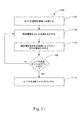
図11に、本発明の一実施形態による、対象の検出に基づいてレーザ光源をシャットダウンする安全方法1100を示す。ブロック1102で、安全プロセッサ162は、カメラの視野を複数の領域に分割し得る。一実施形態では、安全プロセッサ162は、カメラ202の視野を、小さい正方形に分割する。
[0036]
FIG. 11 illustrates a
[0037]
ブロック1104で、安全プロセッサ162は、次いで、安全閾値を超える領域を決定する。例えば、安全プロセッサは、各領域または正方形ごとに、その輝度が所与の閾値を超える画素の数を数えることができる。この数が指定の数字より高い場合、所与の領域は、閾値を上回るとみなされる。ブロック1106で、輝度閾値を超える領域によってカバーされる範囲が決定される。例えば、安全プロセッサ162は、輝度閾値を超えている正方形によってカバーされる範囲のサイズと形状を求めることができる。ブロック1108で、安全プロセッサ162は、この範囲情報を使って、レーザ光源122をシャットダウンすべきかどうか判定する。例えば、対象のサイズと形状を使って、検出されている対象が、シャットダウンの根拠となる人間である可能性が高いか、それとも、虫や鳥など、レーザ光源のシャットダウンの根拠とならないはずの別の対象であるか判定することもできる。
[0037]
At block 1104, the
[0038]
ブロック1108で、安全プロセッサ162が、レーザ光源をシャットダウンすべきでないと判定した場合、方法1100は、ブロック1104に進む。安全プロセッサ162が、レーザ光源をシャットダウンすべきであると判定した場合、安全モジュール128は、ブロック1110でレーザ光源122をシャットダウンする。
[0038]
If the
[0039]
また、安全モジュール128は、ユーザの介在なしで自動的に照射器を回復させることもできる。例えば、安全モジュール128は、レーザの強度を徐々に増大し、目の安全への潜在的な脅威の原因となる、照射器に近すぎる対象の有無を絶えずチェックしてもよい。レーザをシャットダウンする根拠となる対象が検出された場合、レーザ強度は、再度低減されてゼロになる。そうでない場合、レーザの強度は、所望の強さになるまで徐々に増大する。例えば、シャットダウンイベント時において、レーザ強度は0まで下がるが、直後に、小さい値、例えばその最大値の10%程度まで徐々に増大する。次のフィールド時間において、安全プロセッサ162は、この低減された強度で、依然として目の安全への脅威の可能性があるかどうか判定することができる。依然として脅威がある場合、強度は、自動的により小さい値まで下げられる。脅威がない場合、強度は、次のフィールドにおいてより高い値まで上がる。このプロセスは、各時点において最大限の目に安全なレーザ強度が実施されるように続行する。このように、(若干の性能低下を伴った)監視ジョブが、安全シャットダウン後でさえも続行し得る。また、これは、システムが、手動リセットまたはオペレータ対話なしで、夜間監視モードに自動的に復帰することも可能にし、これは、システムが無人である場合には、重要である。
[0039]
The safety module 128 can also automatically restore the irradiator without user intervention. For example, the safety module 128 may continually check for targets that are too close to the illuminator, which gradually increases the intensity of the laser and causes a potential threat to eye safety. If an object that is the basis for shutting down the laser is detected, the laser intensity is again reduced to zero. Otherwise, the laser intensity gradually increases until the desired intensity is reached. For example, at the time of a shutdown event, the laser intensity decreases to 0, but immediately after that, gradually increases to a small value, for example, about 10% of the maximum value. At the next field time, the
[0040]
一実施形態では、安全モジュール128は、レーザがクラス1レーザとして分類され得るように実施される。レーザをクラス1に分類すれば、レーザの使用時にレーザ安全管理者が居合わせる必要がなくなる。
[0040]
In one embodiment, safety module 128 is implemented such that the laser can be classified as a
[0041]
図1に再度戻って、制御ユニット124は、制御コンピュータ150から制御信号を受け取り、制御信号を、レーザ光源122、照射ユニット106、パン/チルトユニット104およびカメラユニット102に送ることができる。レーザ制御信号は、レーザ光源122におけるレーザの強度を制御することができる。照射ユニット制御信号は、レーザ照射ビームのズームを制御するなど、コリメータ204を制御するのに使用され得る。パン/チルトユニット制御信号は、パン/チルトユニット104の動きを制御することができる。カメラユニット制御信号は、ズーム、フォーカス、ゲイン、シャッタ、その他のカメラ制御など、カメラ202を制御するのに使用され得る。
[0041]
Returning again to FIG. 1, the
[0042]
また、電子回路ユニット120は、制御コンピュータまたは他の電源から電力を受け取り、照射ユニット106、パン/チルトユニット104、およびカメラユニット102のみならず、電子回路ユニット120内の構成要素にも電力を提供することのできる電源ユニット126も含むことができる。電源回路126は、受け取った電力を、様々な構成要素が必要とする電力に変換する変換器を含んでいてもよい。また、電子回路ユニット130は、ユニット130の構成要素を冷却する冷却ユニット(不図示)を含んでいてもよい。
[0042]
The electronic circuit unit 120 also receives power from a control computer or other power source and provides power not only to the
ユーザインターフェース
[0043]
図3に、制御コンピュータ150によって生成されるユーザインターフェース300の一実施形態を示す。ユーザインターフェースは、背景画像302と、ライブビデオ画像304と、制御ボタン306を含み得る。図3に示す実施形態において、背景画像302は、カメラ202の対象領域のパノラマ画像であり、カラーで表示される。ライブビデオ画像304は、レーザ照射ビーム230を使ってカメラ202によって取り込まれるカメラ202の現在視野である。ライブビデオ画像304の位置は、この実施形態では、背景画像302上の標識ボックス308によって、背景画像302と相互に関連付けられる。背景画像302と標識ボックス308とは、ユーザに、現在見えている領域に関して即座の方向定位を提供する。この方向定位を達成した後で、ユーザは、検査対象領域をより詳細に見るためにズームインしてもよい。
User interface [0043]
FIG. 3 illustrates one embodiment of a
[0044]
制御ボタン306は、パン/チルトユニット108の動きの制御、カメラ202とコリメータ204の制御、レーザ光源122の制御など、様々な機能を実行することができる。例えば、ユーザは、制御ボタン306を介して、パン/チルトユニット108を制御することによって、カメラ202の視野を移動させることができる。フォーカス、ゲイン、シャッタなどのカメラ202設定は、ユーザにより、制御ボタン306を介して制御され得る。また、カメラ202によって使用されるフィルタ222とカメラ202の安定性設定も、ユーザにより、制御ボタン306を介して制御され得る。ズームやフォーカスなど、コリメータ204の照射器設定は、制御ボタン306を介して制御され得る。また、制御ボタン306は、ユーザにレーザ照射ビームをオンにさせ、レーザ照射ビームの強度とサイズを制御させることもできる。制御ボタン306は、ユーザに、カメラと照射器の焦点距離を、これらが一致して動くようにロックさせることもできる。
[0044]
The
[0045]
ユーザは、制御ボタン306を介して、背景画像302を生成し、そのサイズを設定してもよい。また、制御ボタン306は、ユーザが関心地点または目標と、パノラマ背景画像302内の経路を設定し、目標間をナビゲートするためのインターフェースも提供する。また、制御コンピュータ150は、他の検出システムから情報を受け取り、この情報を表示してもよい。一実施形態では、熱撮像システムが使用され、熱撮像器の位置が、ボックス308と同様の標識を用いて背景画像上に示される。熱撮像器標識ボックスは、ボックス308より大きく、色の異なるものとすることもできる。また、熱撮像器からの画像(不図示)も、ユーザインターフェースでユーザに表示され得る。
[0045]
The user may generate the
[0046]
図4に、ユーザインターフェースの画像部分の代替の実施形態を示す。この実施形態では、パノラマ背景画像402の一部が、背景画像402内に表示され、または融合されたライブビデオ画像404と共に表示される。この領域404は、IR照射器によって照射され、カメラによって撮像される。カメラによって生成されるライブビデオ画像404は、制御コンピュータ150のメモリから取り出される対象領域の調整済み固定画像402に自動的に合成される。この合成画像がユーザに提示される。この実施形態では、部分404だけが、リアルタイムで取り込まれるライブ画像である。合成画像は、ユーザに、ユーザが現在見ている領域に関する即座の方向定位をもたらす。この方向定位を達成した後、ユーザは、検査対象領域を詳細に見るためにズームインしてもよい。ズームインするとき、ライブビデオ画像404は光学的に拡大され、合成領域402は、合成画像全体が、単一の実際の撮像器から発する単一の画像として振る舞うように、光学機器と同期してデジタル的に拡大される。
[0046]
FIG. 4 illustrates an alternative embodiment of the image portion of the user interface. In this embodiment, a portion of the
[0047]
別の実施形態では、ライブビデオ画像は、システムがパンし、またはチルトする場合でさえも、背景画像の中央または別の任意の所定位置に固定される。ユーザがズームインするとき、ライブビデオ画像は光学的に拡大され、背景画像は、背景とライブ画像の全体が、単一の実際の撮像器から発する単一の画像として振る舞うように、光学機器と同期してデジタル的に拡大される。別の実施形態では、背景画像は固定され、ライブビデオ画像部分は、カメラが移動するに従って背景画像フレーム内でその位置を変える。このオプションは、監視システムが、カメラの対象領域内の特定の経路を自動的に追跡する必要があるとき、すなわち「仮想巡回」に役立ち得る。ライブビデオ画像の位置と背景画像を相関させる別のやり方が使用されてもよい。
[0047]
In another embodiment, the live video image is fixed at the center of the background image or at any other predetermined position, even when the system pans or tilts. When the user zooms in, the live video image is optically magnified and the background image is synchronized with the optics so that the entire background and live image behave as a single image originating from a single real imager. And is digitally expanded. In another embodiment, the background image is fixed and the live video image portion changes its position within the background image frame as the camera moves. This option can be useful when the surveillance system needs to automatically track a specific path within the target area of the camera, i.e. "virtual tour". Another way of correlating the position of the live video image with the background image may be used.
方法
[0048]
本発明の実施形態による様々な方法が実行され得る。図5に、図1と2に示すシステム100によって実施され得る監視の例示的方法500を示す。この例示的方法は、例として示すものであり、本発明による方法を実行する様々なやり方がある。図5に示す方法500は、様々なシステムの1つまたはこれらの組み合わせによって実行され、または別様に行われ得る。図1と2に示す前述のシステムを、例として使用する。
Method [0048]
Various methods according to embodiments of the invention may be performed. FIG. 5 illustrates an
[0049]
方法500は、ブロック502で、背景画像の生成から開始する。背景画像は、カメラ202の対象領域の全体または一部を含むパノラマ画像とすることができ、これを図3に画像302で示す。一実施形態では、背景画像は、白昼に作成されるカラー画像である。また、背景画像は、IRフィルタを使って作成され、次いで、カラー背景画像と相互に関連付けられてもよい。IR背景画像は、IR照射を使って取り込まれるライブビデオ画像とのよりよい相関を実現し得る。
[0049]
The
[0050]
一実施形態では、背景画像エンジン158は、カメラ202を、カメラ202の対象領域から複数の画像を取り込むように制御し、次いで、これらの画像をパノラマ画像内に相関させることによって背景画像を生成する。以下の図8で、背景画像生成の例示的方法をより詳細に説明する。
[0050]
In one embodiment, the
[0051]
ブロック504で、ライブビデオ画像が受け取られる。一実施形態では、ライブビデオ画像は、照射器211からのレーザ照射を使ってカメラ202によって取り込まれる。ライブビデオ画像は、カメラ202の現在視野とすることができ、例えば、図3の画像304や図4の画像404で示される。前述のように、コリメータ204の焦点距離は、カメラ202の視野に連動させることができる。また、ユーザは、カメラ202とコリメータ204とレーザ光源122を別々に制御することもできる。
[0051]
At
[0052]
ブロック506で、ライブビデオ画像の位置が背景画像と相互に関連付けられ。カメラ202の瞬間視野は、一般に、カメラ202の対象領域より小さい。したがって、この現在の取り込みライブ画像が、ユーザにとって認識可能な環境の視覚的手掛かりを全く含まない可能性もある。よって、ユーザが空間的方向定位を失い、カメラがどこに向けられており、ライブ画像が対象領域全体のどこに位置しているか分からなくなる可能性がきわめて高い。このため、ユーザにライブビデオ画像の方向定位が提供されるように、ライブビデオ画像と背景画像を相関させることが必要になる。一実施形態では、背景画像内で、ユーザに、ライブビデオ画像が対象領域内のどこに配置されるか示すボックスが設けられる。この実施形態は、例えば、図3にボックス308で示されている。別の実施形態では、ライブビデオ画像は、背景画像内のこれの位置に表示され得る。この実施形態は、例えば、図4に示されている。
[0052]
At
[0053]
暗視カメラのライブビデオ画像とカメラの対象領域の背景画像を相関させるのに、様々な方法が使用され得る。一実施形態では、この相関は、自動リアルタイムプロセスである。
[0053]
Various methods can be used to correlate the night video camera's live video image with the background image of the camera's area of interest. In one embodiment, this correlation is an automatic real-time process.
[0054]
一方法では、ボアサイトカメラのみならず、レーザ照射ビームもまた、その方向が制御コンピュータ150に知られている「復帰位置」を有する。例えば、一実施形態では、パン/チルトユニット104は復帰機能を有し、所与のパン/チルト位置がゼロ位置として定義される。このゼロまたは復帰位置を使用すれば、制御コンピュータ150は、連続するフレーム対フレームの照合計算を使って、視野の瞬間位置を計算することができる。視野方向が分かっていれば、ライブビデオ画像が、制御コンピュータ150によって背景画像に大まかに関連付けられ得る。一実施形態では、次いで、(以下で説明する)パターン照合技術を使って、ライブビデオ画像と背景画像の間のより正確な位置相関が提供される。
[0054]
In one method, not only the boresight camera, but also the laser illumination beam has a “return position” whose direction is known to the
[0055]
別の方法は、パターン照合法を使って、ライブビデオ画像を背景画像内のその正しい位置に整合させ、相関させる。一実施形態では、パターンの認識と照合が、IRフィルタを使って生成される背景画像を使って行われる。次いで、IR背景画像と着色背景画像の間の事前計算された相関を使って、ライブビデオ画像が背景画像に関連付けられる。一実施形態では、2つの背景画像、すなわち、ユーザインターフェース上の表示に使用される着色昼間背景画像と、ブロック/特徴照合に使用される(IRフィルタを使って昼間に取られ、またはレーザ照射を使って夜間に取られる)IR背景画像が相互に関連付けられる。着色背景画像は、照合にも使用され得るが、このプロセスは、IR背景画像を用いた場合ほど成功しないこともある。
[0055]
Another method uses a pattern matching method to align and correlate the live video image with its correct position in the background image. In one embodiment, pattern recognition and matching is performed using a background image generated using an IR filter. The live video image is then associated with the background image using a pre-calculated correlation between the IR background image and the colored background image. In one embodiment, two background images, a colored daytime background image used for display on the user interface, and a block / feature match (taken in the daytime using an IR filter or laser illuminated). IR background images (taken at night using) are correlated. Although colored background images can also be used for matching, this process may not be as successful as with IR background images.
[0056]
別の方法では、視野方向が、(例えば、ポテンショメータや符号器といった)パン、チルトおよびズームセンサを連続して読み取ることによって計算されて、パン角度およびチルト角度とズーム設定が提供される。パンセンサとチルトセンサは、例えば、パン/チルトユニット104内のセンサ109などとすることができる。ズームセンサは、カメラ202および/またはコリメータ204と関連付けることができる。これらのセンサは、現在視野のために制御コンピュータ160に位置情報(パン、チルト角度とズーム設定)を送ることができる。制御コンピュータ150は、この位置情報に基づき、対象領域(背景画像)内の現在視野(ライブビデオ画像)のおおよその位置を計算することができる。一実施形態では、次いで、(前述の)パターン照合技術を使って、ライブビデオ画像と背景画像の間のより正確な位置相関が提供される。
[0056]
In another method, the viewing direction is calculated by sequentially reading pan, tilt and zoom sensors (eg, potentiometers and encoders) to provide pan and tilt angles and zoom settings. The pan sensor and tilt sensor may be, for example, the
[0057]
別の方法は、IR感知位置センサを利用する。このIR位置センサは、その視野がカメラの対象領域全体をカバーするような固定位置に取り付けられてもよい。この位置センサは、複数の照射器のために使用され得る。このセンサは、照射器地点を自動的に検出し、その直径を抽出し、その方向とサイズを制御コンピュータ150に送ることができる。監視システムの場所のみならず、位置センサの場所と姿勢が分かっていれば、制御コンピュータ150は、背景画像上の瞬間レーザスポットの位置を計算することができる。
[0057]
Another method utilizes an IR sensitive position sensor. The IR position sensor may be mounted at a fixed position whose field of view covers the entire target area of the camera. This position sensor can be used for multiple illuminators. This sensor can automatically detect the illuminator point, extract its diameter, and send its direction and size to the
[0058]
本発明の一実施形態では、前述の方法の複数の方法を使って、ライブビデオ画像を背景画像に相関させてもよい。個々のシステムの要件とユーザの必要および予算に応じて、前述の方法の様々な組み合わせが使用され得る。例えば、ライブビデオ画像の位置で最大限の正確さを達成するには、まず、ライブビデオ画像位置の大ざっぱな推定値のためにパン、チルトおよびズームセンサが読み取られ、次いで、精密な方向定位調整のためにビデオ特徴照合が行われてもよい。
[0058]
In one embodiment of the present invention, a live video image may be correlated to a background image using a plurality of methods described above. Various combinations of the above methods may be used depending on the requirements of the individual system and the needs and budgets of the user. For example, to achieve maximum accuracy in the position of the live video image, first the pan, tilt and zoom sensors are read for a rough estimate of the live video image position, and then a precise orientation adjustment Video feature matching may be performed for this purpose.
対象領域の走査
[0059]
カメラによる対象領域の長い走査時間と、対象領域内の所与の地点での「再訪時間」(走査システムの後続巡視間の期間)を克服するために、様々な方法が使用され得る。長い再訪時間は、いくつかの実施形態では、照射器のビーム拡散角度の限界に由来し得る。
Scanning the target area [0059]
Various methods can be used to overcome the long scan time of the target area by the camera and the “revisit time” (period between subsequent visits of the scanning system) at a given point in the target area. The long revisit time may be derived in some embodiments from the limit of the beam spread angle of the illuminator.
[0060]
一方法が、対象領域または仮想巡回における、領域、経路、関心地点などといった関心領域の事前定義である。一実施形態では、ユーザは、例えば、図3に示す制御ボタン306を使用するなど、ユーザインターフェースとの対話を通じて、関心領域または目標を識別し得る。次いで、制御コンピュータ150は、これらの地点を格納し、これらの関心領域のライブビデオ画像を、その対象領域の残りの部分よりも頻繁に、またはユーザ定義の経路に従って取り込むようにカメラを制御し得る。例えば、制御コンピュータ150は、カメラが、ほぼ真直ぐな監視経路を、観察経路の各区間ごとの最適な画像解像度を用いて走査する間、(必要に応じて)カメラのズームとフォーカスのパラメータだけが変更されるようにカメラとIR照射ビームを制御してもよい。
[0060]
One method is the pre-definition of a region of interest such as a region, a route, a point of interest, etc. in the target region or virtual tour. In one embodiment, the user may identify a region of interest or goal through interaction with the user interface, such as using the
[0061]
一実施形態では、仮想巡回プロセスが、制御コンピュータ150が、パン、チルト角度、およびレンズズーム(および必要に応じてフォーカス)値を含むすべてのパラメータを、予定される仮想巡回に沿って動的に指定することを必要とし得る。ユーザは、例えば、ユーザインターフェース300の背景画像302内の地点をクリックすることによって、関心地点および/または関心経路を指定してもよい。これは、システムのセットアップまたは初期設定時にユーザによって行われ得る。仮想経路または巡回が指定されると、システムは、指定の経路または巡回に自動的に従うことができる。
[0061]
In one embodiment, the virtual tour process causes the
[0062]
制御コンピュータ150は、ユーザの選択を、指定の地点から、または指定の経路に沿って画像を取り込むのに必要なカメラ、照明、およびパン/チルトパラメータと相関させることができる。例えば、図3において、「X」は、ユーザによって設定された所定の関心領域または目標を示す。制御コンピュータ150は、背景画像内の目標Xのアドレス情報を、対象領域内の位置情報と相関させることができる。制御コンピュータは、例えば、レーザ照射ビームを使用するカメラを制御して、各目標において左から右へ画像を取り込むことができる。ユーザからの入力に基づき、制御コンピュータ150は、カメラの対象領域内の所定の経路に沿った夜間「仮想巡回」、ならびにその他の洗練された走査パターンを行うようにカメラを制御してもよい。スキャン中を通して動的に変更され得る別のパラメータが、照射器の強度であり、これは、システムが近距離で使用されるときには、偶然に通りかかった人の目の安全を保護し、かつ/または画像飽和を回避するために、低減される必要がある。
[0062]
The
[0063]
かかる仮想巡回の効率的な実施は、撮影用カメラの視野とIR照射器の拡散角度の同期的変更を必要とする。カメラの視野とIR照射器の拡散角度を同期させることによって、照射器ビーム全体の強度の焦点を対象領域の関連部分に当てることが可能になる。一例を図6に示す。ボアサイトカメラの視野内を飛ぶ、601から605で指定する照射ビームスポットは、動的に、カメラレンズズーム機構と同調して、対象領域内の様々な重要地点を有効に見るように変化する。
[0063]
Efficient implementation of such a virtual tour requires a synchronous change of the field of view of the imaging camera and the diffusion angle of the IR illuminator. By synchronizing the camera field of view and the IR illuminator diffusion angle, it is possible to focus the intensity of the entire illuminator beam on the relevant portion of the region of interest. An example is shown in FIG. The irradiation beam spot designated by 601 to 605 that flies in the field of view of the boresight camera dynamically changes in synchronization with the camera lens zoom mechanism so as to effectively view various important points in the target region.
[0064]
システムには、図1に示す検出システム160など、対象領域のインテリジェントな走査を可能にする検出システムが含まれ得る。例えば、走査熱撮像器や対人レーダのような広域検出システムが使用され得る。また、(独立に配置され、またはフェンス上に取り付けられる)近接検出センサを備えるセキュリティシステムが使用されてもよい。検出システム160は、検出位置を制御コンピュータ150に送ることができる。次いで、制御コンピュータは、関心領域からのライブビデオ画像を取り込むようにカメラ視野と照射ビームを誘導することができる。
[0064]
The system may include a detection system that enables intelligent scanning of the region of interest, such as
[0065]
例えば、検出システム160は、対象領域内に位置する一連のセンサを備える警報システムとすることができる。対象領域内の各センサの位置は、システムのセットアップ時に設定される。制御コンピュータ150は、センサから警報信号を受け取ることができ、この信号は、視野を自動的にセンサの方向に向けさせ、レンズズーム値に、潜在的脅威の推定位置を包含させることができる。視野が警報の正確な位置に変化し得る能力は、センサの機能に左右される。例えば、フェンスセンサが、高ズームで、50メートルのフェンスラインに沿った位置を提供する場合、システムは、実際の目標を見るためにパンすることが必要になり得る。
[0065]
For example, the
[0066]
対象領域を走査する別の方法は、対象領域内の動きおよび/または変化の検出と、かかる活動(動く対象、場面に追加された新しい対象、場面から除去された対象)が検出される領域の連続的探査に基づくものである。動く対象、追加対象または除去対象は、後続の走査で作成される全対象領域のモザイク画像の画像処理相関と照合を介して、制御コンピュータ150のビデオ動き/変化検出モジュール157によって自動的に検出され得る。関心領域の自動検出を用いれば、制御コンピュータ150は、カメラを、これらの領域からのライブビデオ画像の取り込みにより多くの時間を費やすように制御することができる。よって、かかる関心地点の再訪時間は、大幅に短縮される。
[0066]
Another way of scanning the target area is to detect movement and / or changes in the target area and to detect such activities (moving objects, new objects added to the scene, objects removed from the scene) Based on continuous exploration. Moving, adding or removing objects are automatically detected by the video motion /
[0067]
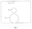
対象領域の走査時間を短縮させる別の方法は、カメラのパン、チルト角度によって指定される、カメラの対象領域内の各地点に、カメラまでの所与の距離が割り当てられ得ることに関連するものである。照射ビームの強度は(第1次近似では)距離の二乗に反比例する。よって、ビームの拡散角度と誘導されるカメラの視野(有界長方形)は、走査プロセスの間動的に変化して、カメラにより近い領域では、照射ビームが比例的に拡大される。これを図7に概略的に示す。円701は、カメラに近い領域における照射ビームである。円702はより離れた場所のビームを表し、円703は、有用な夜間画像を可能にする対象領域内の最も遠い領域に関連するものである。また、制御コンピュータ150は、所与のフレーム内の平均強度または内容情報を測定することによって、ビーム拡散角度と誘導されるカメラの視野を自動的に調整してもよく、これは、対象領域の走査時間を短縮することができる。
[0067]
Another way to shorten the scan time of the target area is related to the fact that a given distance to the camera can be assigned to each point in the target area of the camera, specified by the pan and tilt angles of the camera It is. The intensity of the irradiation beam is inversely proportional to the square of the distance (in the first order approximation). Thus, the beam divergence angle and the guided camera field of view (bounded rectangle) change dynamically during the scanning process, with the illumination beam being proportionally expanded in the region closer to the camera. This is shown schematically in FIG. A circle 701 is an irradiation beam in an area close to the camera. Circle 702 represents a more distant beam and
[0068]
カメラの対象領域の走査中、いくつかの領域が、別の人口または自然の光源によって照射されてもよい。システムがこれらの領域を走査するとき、制御コンピュータ150は、照射ビームをスイッチオフし、カメラの視野をその可能な最高値に動かしてもよい。これらの方法の任意の1つまたは組み合わせを使って、システム100により、対象領域の走査が実施され得る。
[0068]
During scanning of the target area of the camera, some areas may be illuminated by another population or a natural light source. As the system scans these areas, the
背景画像の生成
[0069]
図8に、対象領域の背景画像を生成する例示的方法502を示す。システムが複数のカメラを有する場合、各カメラごとの背景画像が生成され得る。背景画像は、制御コンピュータ150の背景画像エンジン158によって同期エンジン生成され得る。
Generation of background image [0069]
FIG. 8 illustrates an
[0070]
ブロック802で、それぞれがカメラの対象領域の一部に対応するサブ画像が取り込まれる。これらのサブ画像は、カメラ202が対象領域を順次走査することによって取り込まれ得る。対象領域のサブ画像は、好ましくは、生成されるサブ画像の可能な最高の解像度と品質を達成するように、カメラを最大倍率に設定して、白昼に取り込まれる。また、対象領域画像は、より低い解像度オプションを使って取り込まれてもよい。例えば、一実施形態では、単一の広視野画像が取り込まれ、カメラの対象領域を表す背景画像として使用される。カメラがアナログである場合、取り込みサブ画像は、デジタル画像に変換される。取り込みサブ画像は、制御コンピュータ150のメモリ154に格納されてもよい。各サブ画像は、パン/チルト値などの位置情報や、関連付けられるズーム情報などを有していてもよい。
[0070]
At
[0071]
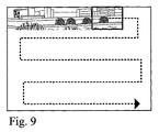
一実施形態では、走査プロセスは、連続するサブ画像フレーム間で若干のオーバーラップ(通常、フレームサイズの1/3)が生じるように行われる。図9に示すように、第1の順次走査は、例えば、複数の連続する垂直スライスによって生成されてもよい。様々な走査パターンを使って、対象領域内の各位置における複数のサブ画像が取り込まれ得る。例えば、初期走査が垂直走査パターンを使って行われる場合、第2の走査は、図10に示すような水平パターン、または対象領域を連続してカバーする他の任意のパターンを使用することができる。複数の走査パターンを使って、対象領域のよりよい全体解像度と、連続フレーム間のよりよい色調整(境界現象の除去)が達成され得る。走査パターンのパターン数と指定は、特定の監視システム要件、時間制限、他のリソース、およびユーザの必要に合わせて調整され得る。
[0071]
In one embodiment, the scanning process is performed such that some overlap (typically 1/3 of the frame size) occurs between successive sub-image frames. As shown in FIG. 9, the first sequential scan may be generated by, for example, a plurality of consecutive vertical slices. A variety of scan patterns can be used to capture multiple sub-images at each location within the region of interest. For example, when the initial scan is performed using a vertical scan pattern, the second scan can use a horizontal pattern as shown in FIG. 10 or any other pattern that continuously covers the target area. . Multiple scan patterns can be used to achieve better overall resolution of the target area and better color adjustment (removal of boundary phenomena) between successive frames. The number and designation of scan patterns can be tailored to specific monitoring system requirements, time limits, other resources, and user needs.
[0072]
ブロック804で、個々のサブ画像が処理される。一実施形態では、個々のサブ画像は、サブ画像から動く対象を除去するように処理される。例えば、人間、車、鳥などの動く対象が、複数の走査の単一のサブ画像またはごく少数のサブ画像に取り込まれてもよい。動く対象は、異なる走査で取り込まれる各サブ画像内の画素の画素値を比較することによって除去され得る。所与の画素は、ある1時点においてのみ動く対象でカバーされるが、大半は「背景値」を示し得る。また、「走査平均」画素を使用すれば、ただ1回の走査だけが使用された場合には全背景画像の少なからぬ歪みを生じ得るはずの、球面などのレンズの歪みも低減され得る。
[0072]
At
[0073]
図8に戻って、領域を走査すると、ブロック806で、背景画像エンジン158は、連続するサブ画像フレームを整合させて、カメラの対象領域の合成画像を生成する。また、ライブ画像と背景画像を相関させる前述の方法は、取り込みサブ画像を整合させて合成背景画像にするのにも使用され得る。例えば、パン/チルトユニット104上のセンサ109からのパン値およびチルト値と、カメラ202と関連付けられたズームセンサからのズーム値が各サブ画像と関連付けられてもよい。これらのパン値、チルト値、およびズーム値を使って、各サブ画像を合成背景画像内に配置することができる。システムは、合成背景画像内の各サブ画像の位置を決定するのに使用され得るIR位置センサを含んでいてもよい。
[0073]
Returning to FIG. 8, when the region is scanned, at
[0074]
別の実施形態では、ブロック照合法やオプティカルフロー法といった画像処理方法を使って、取り込みサブ画像を整合させて合成画像にすることもできる。上記その他の適切な方法の任意の1つまたは組み合わせを使って、複数の取り込みサブ画像から合成背景画像が生成され得る。例えば、まず、パン値、チルト値およびズーム値を使って、サブ画像が大ざっぱに正しい位置に配置され、次いで、画像処理技術を使って、合成画像がさらに洗練されてもよい。
[0074]
In another embodiment, the captured sub-images can be matched to form a composite image using image processing methods such as block matching and optical flow methods. A composite background image can be generated from multiple captured sub-images using any one or combination of the other suitable methods described above. For example, the sub-image may be roughly placed in the correct position first using the pan value, tilt value, and zoom value, and then the composite image may be further refined using image processing techniques.
[0075]
ブロック808で、合成画像はさらに処理される。例えば、合成画像上で均一な色と輝度を提供するために、合成画像上で色相関と輝度相関が行われ得る。また、合成画像上で前述のレンズ歪み除去が行われてもよい。
[0075]
At
[0076]
ブロック810で、自動プロセスによって生じる幾何学的誤差などを補正するために、合成背景画像の手作業による検査が行われ得る。手作業による検査は、ユーザがユーザインターフェースと対話することによって行われる。実施形態によっては、この手作業の検査が行われないものもある。
[0076]
At
[0077]
ブロック812で、対象領域を走査し、IRフィルタを使用するカメラで画像を取り込むことによって別の合成画像が生成される。IRフィルタは、照射器のスペクトルと同様の分光透過を有していてもよい。代替として、このプロセスは、夜間、照射器がオンであるときに、IRフィルタありまたはなしで行うこともできる。生成される対象領域のIR合成画像は、ライブビデオが、特徴照合によって背景画像と関連付けられるときに必要とされ得る。ライブビデオ夜間画像とIR背景画像の間の相関は、対象と地形から反射される光強度が波長依存であることにより、広帯域スペクトルの背景画像との相関よりよくなると期待される。よって、IRコントラストは、可視の広帯域コントラスとは大幅に異なり得る。また、背景IR画像も、ライブビデオ画像と関連付けられ、よって、背景画像の提示に使用され得る。実施形態によっては、合成IR画像が生成されないものもある。
[0077]
At
[0078]
ブロック814で、カラー背景画像とIR背景画像が相互に関連付けられる。この相関は、自動、手動またはその両方で行われ得る。
[0078]
At
[0079]
前述の背景画像作成方法は、設置時に一度だけ行われてもよく、カメラの対象領域内で大きな変更が生じるたびに行われてもよい。カメラが新しい位置に移動されるたびに、このプロセスが反復されるべきことは言うまでもない。この手順は、昼間でも、夜間でも行われ得る。最後の事例では、IR画像生成のために、照射器のスイッチがオンにされている必要がある。また、この手順は、倉庫、駐車場などのような動的環境では、規則的に反復されてもよい。
[0079]
The above-described background image creation method may be performed only once at the time of installation, or may be performed every time a large change occurs in the target area of the camera. Of course, this process should be repeated each time the camera is moved to a new position. This procedure can be performed during the day or at night. In the last case, the illuminator needs to be switched on for IR image generation. This procedure may also be repeated regularly in dynamic environments such as warehouses, parking lots, etc.
[0080]
対象領域の背景画像を生成する別の方法は、当該領域のコンピュータによる3次元モデルの作成を利用するものである。かかるモデルは、この領域の衛星画像と、地形および建物建築のデータを組み合わせて生成され得る。2次元衛星画像が、現実的なテクスチャを有する3次元モデルに変換される。3次元モデルを有し、監視カメラの設置位置が分かっていれば、カメラの視点上に3次元モデルをレンダリングすることによって、各カメラの対象領域の背景画像の作成が可能になる。レンダリングプロセスは、基本的に、仮想カメラ焦点面上に3次元モデルを結像するものであり、最新のグラフィックカードの1つと、市販のソフトウェアグラフィックレンダリングエンジンを備える標準的なパーソナルコンピュータを使って実施され得る。
[0080]
Another method for generating a background image of the target area is to use a three-dimensional model created by a computer in the area. Such a model can be generated by combining satellite imagery of this region with terrain and building architecture data. The two-dimensional satellite image is converted into a three-dimensional model having a realistic texture. If the camera has a three-dimensional model and the installation position of the surveillance camera is known, the background image of the target area of each camera can be created by rendering the three-dimensional model on the camera viewpoint. The rendering process is essentially imaging a 3D model on the focal plane of the virtual camera and is performed using a standard personal computer with one of the latest graphics cards and a commercial software graphics rendering engine. Can be done.
[0081]
後者の方法は、所与の領域内のあらゆる地点からの視野画像の自動生成を可能にし、前者の方法は、幾何学的にも、テクスチャにおいてもはるかに正確な画像を生成する。
[0081]
The latter method allows the automatic generation of field images from any point within a given area, while the former method produces a much more accurate image in both geometry and texture.
総論
[0082]
本発明の、好ましい実施形態を含む、各実施形態の以上の説明は、例示と説明のために示しているにすぎず、網羅的であることも、本発明を開示通りの形に限定することも意図されていない。当分野の技術者には、本発明の精神と範囲を逸脱することなく、本発明の多数の変更と適応が明らかになるであろう。
General [0082]
The foregoing description of each embodiment, including preferred embodiments of the present invention, is presented for purposes of illustration and description only and is exhaustive and limits the invention to the forms disclosed. Also not intended. Numerous variations and adaptations of the present invention will become apparent to those skilled in the art without departing from the spirit and scope of the present invention.
Claims (48)
前記カメラの対象領域の背景画像を生成すること、
前記対象領域内にある、前記カメラの現在視野のライブビデオ画像を受け取ること、および
前記背景画像内で前記ライブビデオ画像の位置を相関させること
を含む方法。 A method for use in a surveillance system having a camera, comprising:
Generating a background image of the target area of the camera;
Receiving a live video image of the camera's current field of view within the region of interest, and correlating the position of the live video image within the background image.
前記対象領域を走査して複数の背景サブ画像を取り込むこと、および
前記サブ画像を整合させて合成画像にすること
を含む請求項1に記載の方法。 Generating the background image comprises:
The method of claim 1, comprising scanning the target region to capture a plurality of background sub-images, and aligning the sub-images into a composite image.
前記背景画像を用いて前記IR背景画像を補正すること
をさらに含む請求項9に記載の方法。 The method of claim 9, further comprising: generating an IR background image; and correcting the IR background image using the background image.
対象領域を有するカメラと、
照射ビームを生成することのできる照射器と、
前記対象領域の背景画像を生成し、前記照射ビームを使って前記カメラによって取り込まれる、前記対象領域内にある前記カメラの現在視野のライブビデオ画像を受け取り、前記背景画像内で前記ライブビデオ画像の位置を相関させることのできるコンピュータと
を備えるシステム。 A night vision monitoring system,
A camera having a target area;
An irradiator capable of generating an irradiation beam;
Generating a background image of the target area, receiving a live video image of the current field of view of the camera within the target area, captured by the camera using the illumination beam, and generating a live video image of the live video image within the background image; A system comprising a computer capable of correlating positions.
前記カメラの対象領域の背景画像を生成すること、
前記対象領域内の少なくとも1つの関心領域(AOI)の位置に対応するAOI位置情報に基づいて前記対象領域を走査すること、
前記少なくとも1つのAOIをカバーする、前記対象領域内にある前記カメラの現在視野のライブビデオ画像を受け取ること、および
前記背景画像内で前記ライブビデオ画像の位置を相関させること
を含む方法。 A monitoring method using at least one camera,
Generating a background image of the target area of the camera;
Scanning the target area based on AOI position information corresponding to a position of at least one region of interest (AOI) within the target area;
Receiving a live video image of the current field of view of the camera within the region of interest that covers the at least one AOI, and correlating the position of the live video image within the background image.
対象領域を有するカメラと、
照射ビームを生成することのできる赤外線(IR)照射器であり、視差を生じるように前記カメラから分離されている前記照射器と、
前記カメラと前記照射器を制御することのできるコンピュータと
を備えるシステム。 A night vision monitoring system,
A camera having a target area;
An infrared (IR) irradiator capable of generating an illumination beam, wherein the illuminator is separated from the camera to produce parallax;
A system comprising the camera and a computer capable of controlling the irradiator.
対象領域を有するカメラと、
照射ビームを生成することのできる赤外線(IR)照射器と、
前記カメラと前記照射器を制御することのできるコンピュータと、
前記照射器に近すぎる対象の有無を検出し、前記照射ビームを遮断することのできる安全モジュールと
を備えるシステム。 A night vision monitoring system,
A camera having a target area;
An infrared (IR) irradiator capable of generating an illumination beam;
A computer capable of controlling the camera and the irradiator;
A safety module capable of detecting the presence or absence of an object too close to the irradiator and blocking the irradiation beam.
Applications Claiming Priority (2)
| Application Number | Priority Date | Filing Date | Title |
|---|---|---|---|
| US64024405P | 2005-01-03 | 2005-01-03 | |
| PCT/US2006/000084 WO2006074161A2 (en) | 2005-01-03 | 2006-01-03 | Systems and methods for night time surveillance |
Publications (1)
| Publication Number | Publication Date |
|---|---|
| JP2008527806A true JP2008527806A (en) | 2008-07-24 |
Family
ID=36218812
Family Applications (1)
| Application Number | Title | Priority Date | Filing Date |
|---|---|---|---|
| JP2007549706A Pending JP2008527806A (en) | 2005-01-03 | 2006-01-03 | Night monitoring system and method |
Country Status (8)
| Country | Link |
|---|---|
| US (1) | US20060238617A1 (en) |
| EP (2) | EP1834312A2 (en) |
| JP (1) | JP2008527806A (en) |
| KR (1) | KR20070106709A (en) |
| IL (2) | IL184263A (en) |
| IN (1) | IN2007KN02527A (en) |
| RU (1) | RU2452033C2 (en) |
| WO (1) | WO2006074161A2 (en) |
Cited By (4)
| Publication number | Priority date | Publication date | Assignee | Title |
|---|---|---|---|---|
| WO2016163216A1 (en) * | 2015-04-10 | 2016-10-13 | シャープ株式会社 | Infrared projector and infrared observation system |
| JP2016194778A (en) * | 2015-03-31 | 2016-11-17 | セコム株式会社 | Object detection device |
| JP2017528044A (en) * | 2014-07-24 | 2017-09-21 | ボリーメディア ホールディングス カンパニー リミテッドBolymedia Holdings Co. Ltd. | Night vision device |
| WO2024004534A1 (en) * | 2022-06-27 | 2024-01-04 | 富士フイルム株式会社 | Information processing device, information processing method, and information processing program |
Families Citing this family (143)
| Publication number | Priority date | Publication date | Assignee | Title |
|---|---|---|---|---|
| US7221287B2 (en) | 2002-03-05 | 2007-05-22 | Triangle Software Llc | Three-dimensional traffic report |
| WO2005013063A2 (en) | 2003-07-25 | 2005-02-10 | Landsonar, Inc. | System and method for determining recommended departure time |
| US20170118037A1 (en) | 2008-08-11 | 2017-04-27 | Icontrol Networks, Inc. | Integrated cloud system for premises automation |
| US11343380B2 (en) | 2004-03-16 | 2022-05-24 | Icontrol Networks, Inc. | Premises system automation |
| US10200504B2 (en) | 2007-06-12 | 2019-02-05 | Icontrol Networks, Inc. | Communication protocols over internet protocol (IP) networks |
| US20160065414A1 (en) | 2013-06-27 | 2016-03-03 | Ken Sundermeyer | Control system user interface |
| US11277465B2 (en) | 2004-03-16 | 2022-03-15 | Icontrol Networks, Inc. | Generating risk profile using data of home monitoring and security system |
| US10522026B2 (en) | 2008-08-11 | 2019-12-31 | Icontrol Networks, Inc. | Automation system user interface with three-dimensional display |
| US11159484B2 (en) | 2004-03-16 | 2021-10-26 | Icontrol Networks, Inc. | Forming a security network including integrated security system components and network devices |
| US10339791B2 (en) | 2007-06-12 | 2019-07-02 | Icontrol Networks, Inc. | Security network integrated with premise security system |
| US8635350B2 (en) | 2006-06-12 | 2014-01-21 | Icontrol Networks, Inc. | IP device discovery systems and methods |
| US9141276B2 (en) | 2005-03-16 | 2015-09-22 | Icontrol Networks, Inc. | Integrated interface for mobile device |
| US7711796B2 (en) | 2006-06-12 | 2010-05-04 | Icontrol Networks, Inc. | Gateway registry methods and systems |
| US11113950B2 (en) | 2005-03-16 | 2021-09-07 | Icontrol Networks, Inc. | Gateway integrated with premises security system |
| US11368429B2 (en) | 2004-03-16 | 2022-06-21 | Icontrol Networks, Inc. | Premises management configuration and control |
| US11201755B2 (en) | 2004-03-16 | 2021-12-14 | Icontrol Networks, Inc. | Premises system management using status signal |
| US10127802B2 (en) | 2010-09-28 | 2018-11-13 | Icontrol Networks, Inc. | Integrated security system with parallel processing architecture |
| US11582065B2 (en) | 2007-06-12 | 2023-02-14 | Icontrol Networks, Inc. | Systems and methods for device communication |
| US10721087B2 (en) | 2005-03-16 | 2020-07-21 | Icontrol Networks, Inc. | Method for networked touchscreen with integrated interfaces |
| US20090077623A1 (en) | 2005-03-16 | 2009-03-19 | Marc Baum | Security Network Integrating Security System and Network Devices |
| US10237237B2 (en) | 2007-06-12 | 2019-03-19 | Icontrol Networks, Inc. | Communication protocols in integrated systems |
| US11677577B2 (en) | 2004-03-16 | 2023-06-13 | Icontrol Networks, Inc. | Premises system management using status signal |
| US11316958B2 (en) | 2008-08-11 | 2022-04-26 | Icontrol Networks, Inc. | Virtual device systems and methods |
| US9531593B2 (en) | 2007-06-12 | 2016-12-27 | Icontrol Networks, Inc. | Takeover processes in security network integrated with premise security system |
| US11811845B2 (en) | 2004-03-16 | 2023-11-07 | Icontrol Networks, Inc. | Communication protocols over internet protocol (IP) networks |
| US11244545B2 (en) | 2004-03-16 | 2022-02-08 | Icontrol Networks, Inc. | Cross-client sensor user interface in an integrated security network |
| AU2005223267B2 (en) | 2004-03-16 | 2010-12-09 | Icontrol Networks, Inc. | Premises management system |
| US10142392B2 (en) | 2007-01-24 | 2018-11-27 | Icontrol Networks, Inc. | Methods and systems for improved system performance |
| US11489812B2 (en) | 2004-03-16 | 2022-11-01 | Icontrol Networks, Inc. | Forming a security network including integrated security system components and network devices |
| US20120066608A1 (en) | 2005-03-16 | 2012-03-15 | Ken Sundermeyer | Control system user interface |
| US10156959B2 (en) | 2005-03-16 | 2018-12-18 | Icontrol Networks, Inc. | Cross-client sensor user interface in an integrated security network |
| US9729342B2 (en) | 2010-12-20 | 2017-08-08 | Icontrol Networks, Inc. | Defining and implementing sensor triggered response rules |
| US11916870B2 (en) | 2004-03-16 | 2024-02-27 | Icontrol Networks, Inc. | Gateway registry methods and systems |
| US11496568B2 (en) | 2005-03-16 | 2022-11-08 | Icontrol Networks, Inc. | Security system with networked touchscreen |
| US11700142B2 (en) | 2005-03-16 | 2023-07-11 | Icontrol Networks, Inc. | Security network integrating security system and network devices |
| US20170180198A1 (en) | 2008-08-11 | 2017-06-22 | Marc Baum | Forming a security network including integrated security system components |
| US20120324566A1 (en) | 2005-03-16 | 2012-12-20 | Marc Baum | Takeover Processes In Security Network Integrated With Premise Security System |
| US20110128378A1 (en) | 2005-03-16 | 2011-06-02 | Reza Raji | Modular Electronic Display Platform |
| US9306809B2 (en) | 2007-06-12 | 2016-04-05 | Icontrol Networks, Inc. | Security system with networked touchscreen |
| US11615697B2 (en) | 2005-03-16 | 2023-03-28 | Icontrol Networks, Inc. | Premise management systems and methods |
| US10999254B2 (en) | 2005-03-16 | 2021-05-04 | Icontrol Networks, Inc. | System for data routing in networks |
| JP4244973B2 (en) | 2005-08-03 | 2009-03-25 | ソニー株式会社 | Imaging system, camera control device, panoramic image display method and program |
| US10079839B1 (en) | 2007-06-12 | 2018-09-18 | Icontrol Networks, Inc. | Activation of gateway device |
| US8775452B2 (en) * | 2006-09-17 | 2014-07-08 | Nokia Corporation | Method, apparatus and computer program product for providing standard real world to virtual world links |
| US11706279B2 (en) | 2007-01-24 | 2023-07-18 | Icontrol Networks, Inc. | Methods and systems for data communication |
| US7633385B2 (en) | 2007-02-28 | 2009-12-15 | Ucontrol, Inc. | Method and system for communicating with and controlling an alarm system from a remote server |
| ATE473474T1 (en) * | 2007-03-30 | 2010-07-15 | Abb Research Ltd | METHOD FOR OPERATING REMOTE-CONTROLLED CAMERAS IN AN INDUSTRIAL PROCESS |
| US8451986B2 (en) | 2007-04-23 | 2013-05-28 | Icontrol Networks, Inc. | Method and system for automatically providing alternate network access for telecommunications |
| US11646907B2 (en) | 2007-06-12 | 2023-05-09 | Icontrol Networks, Inc. | Communication protocols in integrated systems |
| US11316753B2 (en) | 2007-06-12 | 2022-04-26 | Icontrol Networks, Inc. | Communication protocols in integrated systems |
| US11423756B2 (en) | 2007-06-12 | 2022-08-23 | Icontrol Networks, Inc. | Communication protocols in integrated systems |
| US10666523B2 (en) | 2007-06-12 | 2020-05-26 | Icontrol Networks, Inc. | Communication protocols in integrated systems |
| US11237714B2 (en) | 2007-06-12 | 2022-02-01 | Control Networks, Inc. | Control system user interface |
| US10523689B2 (en) | 2007-06-12 | 2019-12-31 | Icontrol Networks, Inc. | Communication protocols over internet protocol (IP) networks |
| US11212192B2 (en) | 2007-06-12 | 2021-12-28 | Icontrol Networks, Inc. | Communication protocols in integrated systems |
| US11218878B2 (en) | 2007-06-12 | 2022-01-04 | Icontrol Networks, Inc. | Communication protocols in integrated systems |
| US11601810B2 (en) | 2007-06-12 | 2023-03-07 | Icontrol Networks, Inc. | Communication protocols in integrated systems |
| US11089122B2 (en) | 2007-06-12 | 2021-08-10 | Icontrol Networks, Inc. | Controlling data routing among networks |
| US20180198788A1 (en) * | 2007-06-12 | 2018-07-12 | Icontrol Networks, Inc. | Security system integrated with social media platform |
| US8009178B2 (en) * | 2007-06-29 | 2011-08-30 | Microsoft Corporation | Augmenting images for panoramic display |
| US8866883B2 (en) * | 2007-06-29 | 2014-10-21 | 3M Innovative Properties Company | Synchronized views of video data and three-dimensional model data |
| US11831462B2 (en) | 2007-08-24 | 2023-11-28 | Icontrol Networks, Inc. | Controlling data routing in premises management systems |
| KR100909808B1 (en) * | 2007-11-13 | 2009-07-29 | 인하대학교 산학협력단 | Image input device using variable illumination and its method |
| RU2498408C2 (en) * | 2007-12-10 | 2013-11-10 | Абб Рисерч Лтд | Computer-implemented method and system for remote control of production process |
| US11916928B2 (en) | 2008-01-24 | 2024-02-27 | Icontrol Networks, Inc. | Communication protocols over internet protocol (IP) networks |
| GB2456802A (en) * | 2008-01-24 | 2009-07-29 | Areograph Ltd | Image capture and motion picture generation using both motion camera and scene scanning imaging systems |
| JP4893649B2 (en) * | 2008-02-08 | 2012-03-07 | 富士通株式会社 | Bandwidth control server, bandwidth control program, and monitoring system |
| US7902979B2 (en) * | 2008-04-11 | 2011-03-08 | Raytheon Company | Directed energy beam virtual fence |
| US20170185278A1 (en) | 2008-08-11 | 2017-06-29 | Icontrol Networks, Inc. | Automation system user interface |
| US8144232B2 (en) * | 2008-07-03 | 2012-03-27 | Sony Ericsson Mobile Communications Ab | Camera system and method for picture sharing using geotagged pictures |
| US11758026B2 (en) | 2008-08-11 | 2023-09-12 | Icontrol Networks, Inc. | Virtual device systems and methods |
| US11258625B2 (en) | 2008-08-11 | 2022-02-22 | Icontrol Networks, Inc. | Mobile premises automation platform |
| US11729255B2 (en) | 2008-08-11 | 2023-08-15 | Icontrol Networks, Inc. | Integrated cloud system with lightweight gateway for premises automation |
| US10530839B2 (en) | 2008-08-11 | 2020-01-07 | Icontrol Networks, Inc. | Integrated cloud system with lightweight gateway for premises automation |
| US11792036B2 (en) | 2008-08-11 | 2023-10-17 | Icontrol Networks, Inc. | Mobile premises automation platform |
| EP2345955A4 (en) * | 2008-10-30 | 2012-05-30 | Sharp Kk | Mobile information terminal |
| US8711218B2 (en) * | 2009-02-09 | 2014-04-29 | Verint Systems, Ltd. | Continuous geospatial tracking system and method |
| DE102009009698B4 (en) * | 2009-02-19 | 2010-11-18 | Eads Deutschland Gmbh | A method for eye-safe operation of a pulsed noise laser in a DIRCM system |
| US9046924B2 (en) | 2009-03-04 | 2015-06-02 | Pelmorex Canada Inc. | Gesture based interaction with traffic data |
| US8982116B2 (en) * | 2009-03-04 | 2015-03-17 | Pelmorex Canada Inc. | Touch screen based interaction with traffic data |
| US8619072B2 (en) | 2009-03-04 | 2013-12-31 | Triangle Software Llc | Controlling a three-dimensional virtual broadcast presentation |
| EP2417559A4 (en) * | 2009-04-08 | 2015-06-24 | Stergen Hi Tech Ltd | Method and system for creating three-dimensional viewable video from a single video stream |
| US8638211B2 (en) | 2009-04-30 | 2014-01-28 | Icontrol Networks, Inc. | Configurable controller and interface for home SMA, phone and multimedia |
| IL199763B (en) * | 2009-07-08 | 2018-07-31 | Elbit Systems Ltd | Automatic video surveillance system and method |
| JP2011035752A (en) * | 2009-08-04 | 2011-02-17 | Olympus Corp | Imaging apparatus |
| US20110043689A1 (en) * | 2009-08-18 | 2011-02-24 | Wesley Kenneth Cobb | Field-of-view change detection |
| US20160360121A1 (en) * | 2009-11-09 | 2016-12-08 | Yi-Chuan Cheng | Portable device with successive extension zooming capability |
| US9766089B2 (en) * | 2009-12-14 | 2017-09-19 | Nokia Technologies Oy | Method and apparatus for correlating and navigating between a live image and a prerecorded panoramic image |
| JP2011155361A (en) * | 2010-01-26 | 2011-08-11 | Sony Corp | Imaging apparatus, imaging control method, and program |
| US9357183B2 (en) * | 2010-03-17 | 2016-05-31 | The Cordero Group | Method and system for light-based intervention |
| DE102010024054A1 (en) * | 2010-06-16 | 2012-05-10 | Fast Protect Ag | Method for assigning video image of real world to three-dimensional computer model for surveillance in e.g. airport, involves associating farther pixel of video image to one coordinate point based on pixel coordinate point pair |
| US8836467B1 (en) | 2010-09-28 | 2014-09-16 | Icontrol Networks, Inc. | Method, system and apparatus for automated reporting of account and sensor zone information to a central station |
| US20120081547A1 (en) * | 2010-10-05 | 2012-04-05 | Bernd Sitzmann | Conducting surveillance using a digital picture frame |
| JP5791256B2 (en) * | 2010-10-21 | 2015-10-07 | キヤノン株式会社 | Display control apparatus and display control method |
| JP5853359B2 (en) | 2010-11-11 | 2016-02-09 | ソニー株式会社 | IMAGING DEVICE, IMAGING DEVICE CONTROL METHOD, AND PROGRAM |
| JP5652142B2 (en) | 2010-11-11 | 2015-01-14 | ソニー株式会社 | Imaging apparatus, display control method, and program |
| US11750414B2 (en) | 2010-12-16 | 2023-09-05 | Icontrol Networks, Inc. | Bidirectional security sensor communication for a premises security system |
| US9147337B2 (en) | 2010-12-17 | 2015-09-29 | Icontrol Networks, Inc. | Method and system for logging security event data |
| EP2490439B1 (en) * | 2011-02-18 | 2013-07-03 | Axis AB | Illumination device for a monitoring camera |
| US9305963B2 (en) | 2011-04-08 | 2016-04-05 | Lasermax, Inc. | Marking system and method |
| RU2460142C1 (en) * | 2011-04-26 | 2012-08-27 | Владимир Андреевич Куделькин | Method of protecting linear section of boundary |
| WO2012159083A2 (en) | 2011-05-18 | 2012-11-22 | Triangle Software Llc | System for providing traffic data and driving efficiency data |
| JP2013034081A (en) | 2011-08-02 | 2013-02-14 | Sony Corp | Image processing device, control method therefor, and program |
| JP6056127B2 (en) * | 2011-10-31 | 2017-01-11 | ソニー株式会社 | Information processing apparatus, information processing method, and program |
| US8781718B2 (en) | 2012-01-27 | 2014-07-15 | Pelmorex Canada Inc. | Estimating time travel distributions on signalized arterials |
| RU2582853C2 (en) | 2012-06-29 | 2016-04-27 | Общество с ограниченной ответственностью "Системы Компьютерного зрения" | Device for determining distance and speed of objects based on stereo approach |
| US10223909B2 (en) | 2012-10-18 | 2019-03-05 | Uber Technologies, Inc. | Estimating time travel distributions on signalized arterials |
| NO334902B1 (en) * | 2012-12-07 | 2014-07-07 | Kongsberg Defence & Aerospace As | System and method for monitoring at least one observation area |
| US9746553B2 (en) * | 2012-12-19 | 2017-08-29 | Sony Corporation | Method for generating an image and handheld screening device |
| US9251692B2 (en) * | 2013-03-15 | 2016-02-02 | Honeywell International Inc. | GPS directed intrusion system with data acquisition |
| US20140300691A1 (en) * | 2013-04-04 | 2014-10-09 | Panasonic Corporation | Imaging system |
| US20160086018A1 (en) * | 2013-04-26 | 2016-03-24 | West Virginia High Technology Consortium Foundation, Inc. | Facial recognition method and apparatus |
| EP3000102A1 (en) | 2013-05-23 | 2016-03-30 | Sony Corporation | Surveillance apparatus having an optical camera and a radar sensor |
| US20140362212A1 (en) * | 2013-06-05 | 2014-12-11 | Lku Technology Ltd. | Illuminating surveillance camera |
| JP5506990B1 (en) * | 2013-07-11 | 2014-05-28 | パナソニック株式会社 | Tracking support device, tracking support system, and tracking support method |
| JP5438861B1 (en) * | 2013-07-11 | 2014-03-12 | パナソニック株式会社 | Tracking support device, tracking support system, and tracking support method |
| CA2856896A1 (en) | 2013-07-18 | 2015-01-18 | Spo Systems Inc. Limited | Virtual video patrol system and components therefor |
| JP6071866B2 (en) * | 2013-12-18 | 2017-02-01 | キヤノン株式会社 | Display control device, display device, imaging system, display control method, and program |
| US11405463B2 (en) | 2014-03-03 | 2022-08-02 | Icontrol Networks, Inc. | Media content management |
| US11146637B2 (en) | 2014-03-03 | 2021-10-12 | Icontrol Networks, Inc. | Media content management |
| US9924143B2 (en) * | 2014-09-23 | 2018-03-20 | Intel Corporation | Wearable mediated reality system and method |
| US10070077B2 (en) | 2014-09-26 | 2018-09-04 | Sensormatic Electronics, LLC | System and method for automated camera guard tour operation |
| US10033924B2 (en) | 2014-10-10 | 2018-07-24 | Iec Infrared Systems, Llc | Panoramic view imaging system |
| US9241104B1 (en) * | 2014-10-30 | 2016-01-19 | Htc Corporation | Panorama photographing method |
| JP5999394B2 (en) * | 2015-02-20 | 2016-09-28 | パナソニックIpマネジメント株式会社 | Tracking support device, tracking support system, and tracking support method |
| JP6399356B2 (en) * | 2015-05-26 | 2018-10-03 | パナソニックIpマネジメント株式会社 | Tracking support device, tracking support system, and tracking support method |
| JP6586824B2 (en) | 2015-08-27 | 2019-10-09 | 富士通株式会社 | Image processing apparatus, image processing method, and image processing program |
| FR3040848B1 (en) * | 2015-09-08 | 2018-02-23 | Safran Electronics & Defense | METHOD AND SYSTEM FOR BISTATIC IMAGING |
| RU2695415C2 (en) * | 2015-09-08 | 2019-07-23 | Владимир Викторович Хопов | Method of determining degree and location of disturbance of zone fiber-optic protection system of objects and device for its implementation |
| RU2628916C2 (en) * | 2015-10-14 | 2017-08-22 | Общество с ограниченной ответственностью "АВТОДОРИЯ" (ООО "АВТОДОРИЯ") | Method and system of controlling stationary camera |
| KR101751020B1 (en) * | 2015-12-08 | 2017-07-11 | 한국해양과학기술원 | Method and apparatus for detecting hns using images from multiple satellites |
| US11190653B2 (en) * | 2016-07-26 | 2021-11-30 | Adobe Inc. | Techniques for capturing an image within the context of a document |
| US9791557B1 (en) * | 2016-09-15 | 2017-10-17 | Qualcomm Incorporated | System and method for multi-area LIDAR ranging |
| WO2018193704A1 (en) * | 2017-04-20 | 2018-10-25 | ソニー株式会社 | Signal processing system, signal processing device, and signal processing method |
| JP6924079B2 (en) * | 2017-06-12 | 2021-08-25 | キヤノン株式会社 | Information processing equipment and methods and programs |
| RU2670429C1 (en) | 2017-11-24 | 2018-10-23 | ООО "Ай Ти Ви групп" | Systems and methods of tracking moving objects on video image |
| US10924685B2 (en) * | 2018-05-07 | 2021-02-16 | Rubicon Products, LLC | Night vision apparatus |
| US10274979B1 (en) * | 2018-05-22 | 2019-04-30 | Capital One Services, Llc | Preventing image or video capture of input data provided to a transaction device |
| US10438010B1 (en) | 2018-12-19 | 2019-10-08 | Capital One Services, Llc | Obfuscation of input data provided to a transaction device |
| CN113542581A (en) | 2020-04-22 | 2021-10-22 | 华为技术有限公司 | View finding method of multi-channel video, graphical user interface and electronic equipment |
| US11516391B2 (en) * | 2020-06-18 | 2022-11-29 | Qualcomm Incorporated | Multiple camera system for wide angle imaging |
| US20230025380A1 (en) * | 2021-07-16 | 2023-01-26 | Qualcomm Incorporated | Multiple camera system |
| KR20240000070A (en) | 2022-06-23 | 2024-01-02 | 디케이엠텍 주식회사 | Sea area automatic monitoring device |
Citations (14)
| Publication number | Priority date | Publication date | Assignee | Title |
|---|---|---|---|---|
| JPS59180472A (en) * | 1983-03-31 | 1984-10-13 | Nec Corp | Laser radar system |
| JPH04169887A (en) * | 1990-11-01 | 1992-06-17 | Matsushita Electric Ind Co Ltd | Laser visual sensor device |
| JPH08304550A (en) * | 1995-05-09 | 1996-11-22 | Nikon Corp | Radar equipment |
| JPH10332322A (en) * | 1997-05-29 | 1998-12-18 | Omron Corp | Distance measuring equipment |
| JPH11331833A (en) * | 1998-05-15 | 1999-11-30 | Hitachi Ltd | Wide visual field monitoring camera system |
| JP2000101991A (en) * | 1998-09-22 | 2000-04-07 | Canon Inc | Remote control method for image pickup device, remote controller, controller and image pickup system |
| JP2000134611A (en) * | 1998-10-21 | 2000-05-12 | Mitsubishi Electric Corp | Trespasser monitoring device |
| JP2000253310A (en) * | 1998-07-21 | 2000-09-14 | Canon Inc | Image processor, its method, storage medium and its system |
| JP2001186504A (en) * | 1999-12-27 | 2001-07-06 | Matsushita Electric Ind Co Ltd | Ship's name read system and ship's name read method |
| JP2001251608A (en) * | 2000-03-07 | 2001-09-14 | Nec Eng Ltd | Remote monitoring camera system |
| JP2002324235A (en) * | 2001-04-24 | 2002-11-08 | Matsushita Electric Ind Co Ltd | Method for compositing and displaying image of on-vehicle camera and device for the same |
| JP2002369046A (en) * | 2001-06-06 | 2002-12-20 | Kawasaki Heavy Ind Ltd | Supervisory device |
| JP2003143473A (en) * | 2001-10-31 | 2003-05-16 | Nippon Hoso Kyokai <Nhk> | Background picture generator and its program |
| JP2003289533A (en) * | 2002-03-28 | 2003-10-10 | Usc Corp | Ultra-telescopic monitor |
Family Cites Families (40)
| Publication number | Priority date | Publication date | Assignee | Title |
|---|---|---|---|---|
| US3595987A (en) * | 1969-02-20 | 1971-07-27 | Ass Motion Picture Tv Prod | Electronic composite photography |
| US4937702A (en) * | 1987-05-06 | 1990-06-26 | Minoru Fukumitsu | Light intensity controller using a proximity sensor |
| JPS6432769A (en) * | 1987-07-29 | 1989-02-02 | Fujitsu General Ltd | Supervising camera equipment |
| US4948210A (en) * | 1988-06-20 | 1990-08-14 | Murasa International | Infrared zoom illuminator |
| US4991183A (en) * | 1990-03-02 | 1991-02-05 | Meyers Brad E | Target illuminators and systems employing same |
| US5117221A (en) * | 1990-08-16 | 1992-05-26 | Bright Technologies, Inc. | Laser image projection system with safety means |
| US5055697A (en) * | 1990-08-24 | 1991-10-08 | Electro-Mechanical Imagineering, Inc. | Infrared radiator |
| US5456157A (en) * | 1992-12-02 | 1995-10-10 | Computing Devices Canada Ltd. | Weapon aiming system |
| US5396069A (en) * | 1993-07-01 | 1995-03-07 | The United States Of America As Represented By The Secretary Of The Air Force | Portable monocular night vision apparatus |
| US5500700A (en) * | 1993-11-16 | 1996-03-19 | Foto Fantasy, Inc. | Method of creating a composite print including the user's image |
| JPH08147477A (en) * | 1994-09-20 | 1996-06-07 | Fujitsu Ltd | Local area image tracking device |
| US6034740A (en) * | 1995-10-30 | 2000-03-07 | Kabushiki Kaisha Photron | Keying system and composite image producing method |
| JP3374651B2 (en) * | 1996-03-29 | 2003-02-10 | ソニー株式会社 | Digital electronic imaging apparatus and imaging method |
| DE19809210A1 (en) * | 1998-03-04 | 1999-09-16 | Siemens Ag | Locality or workplace surveillance method |
| US6816184B1 (en) * | 1998-04-30 | 2004-11-09 | Texas Instruments Incorporated | Method and apparatus for mapping a location from a video image to a map |
| US7023913B1 (en) * | 2000-06-14 | 2006-04-04 | Monroe David A | Digital security multimedia sensor |
| TW407430B (en) * | 1999-04-12 | 2000-10-01 | Defence Dept Chung Shan Inst | Low impure light night vision system light source control method and the apparatus thereof |
| US6563529B1 (en) * | 1999-10-08 | 2003-05-13 | Jerry Jongerius | Interactive system for displaying detailed view and direction in panoramic images |
| IT1310318B1 (en) * | 1999-11-09 | 2002-02-11 | C R A F T S R L | VEHICLE TRAFFIC SURVEILLANCE AND CONTROL SYSTEM ON ROADS AND HIGHWAYS |
| US7522186B2 (en) * | 2000-03-07 | 2009-04-21 | L-3 Communications Corporation | Method and apparatus for providing immersive surveillance |
| US6731825B1 (en) * | 2000-07-11 | 2004-05-04 | Sarnoff Corporation | Apparatus and method for producing images using digitally stored dynamic background sets |
| US7345277B2 (en) * | 2000-08-09 | 2008-03-18 | Evan Zhang | Image intensifier and LWIR fusion/combination system |
| US6420704B1 (en) * | 2000-12-07 | 2002-07-16 | Trw Inc. | Method and system for improving camera infrared sensitivity using digital zoom |
| RU2189066C1 (en) * | 2001-02-15 | 2002-09-10 | Государственное унитарное предприятие "Альфа" | Infra-red night vision device |
| GB2378339A (en) * | 2001-07-31 | 2003-02-05 | Hewlett Packard Co | Predictive control of multiple image capture devices. |
| US6812846B2 (en) * | 2001-09-28 | 2004-11-02 | Koninklijke Philips Electronics N.V. | Spill detector based on machine-imaging |
| US20030093805A1 (en) * | 2001-11-15 | 2003-05-15 | Gin J.M. Jack | Dual camera surveillance and control system |
| CA2390265C (en) * | 2001-12-03 | 2004-08-24 | Inter-Cite Video Inc. | Video security and control system |
| US7167197B2 (en) * | 2002-03-22 | 2007-01-23 | Bae Systems Controls, Inc. | Apparatus and method to evaluate an illuminated panel |
| US7321386B2 (en) * | 2002-08-01 | 2008-01-22 | Siemens Corporate Research, Inc. | Robust stereo-driven video-based surveillance |
| US7024054B2 (en) * | 2002-09-27 | 2006-04-04 | Eastman Kodak Company | Method and system for generating a foreground mask for a composite image |
| US7398481B2 (en) * | 2002-12-10 | 2008-07-08 | Science Applications International Corporation (Saic) | Virtual environment capture |
| CN2601414Y (en) * | 2003-02-13 | 2004-01-28 | 北京中都创新科技有限公司 | Infrared illuminator |
| US6902299B2 (en) * | 2003-02-27 | 2005-06-07 | Cantronic Systems Inc. | Long distance illuminator |
| DE10310636A1 (en) * | 2003-03-10 | 2004-09-30 | Mobotix Ag | monitoring device |
| CN100395775C (en) * | 2003-03-28 | 2008-06-18 | 富士通株式会社 | Camera, light source control method, and computer program |
| WO2005017739A1 (en) * | 2003-08-19 | 2005-02-24 | Koninklijke Philips Electronics N.V. | A visual content signal display apparatus and a method of displaying a visual content signal therefor |
| US7629995B2 (en) * | 2004-08-06 | 2009-12-08 | Sony Corporation | System and method for correlating camera views |
| US20080151052A1 (en) * | 2006-11-01 | 2008-06-26 | Videolarm, Inc. | Infrared illuminator with variable beam angle |
| US20100060733A1 (en) * | 2008-09-06 | 2010-03-11 | Balaji Lakshmanan | Remote surveillance system |
-
2006
- 2006-01-03 EP EP06717309A patent/EP1834312A2/en not_active Ceased
- 2006-01-03 US US11/325,147 patent/US20060238617A1/en not_active Abandoned
- 2006-01-03 WO PCT/US2006/000084 patent/WO2006074161A2/en active Application Filing
- 2006-01-03 RU RU2007129751/07A patent/RU2452033C2/en not_active IP Right Cessation
- 2006-01-03 KR KR1020077017953A patent/KR20070106709A/en not_active Application Discontinuation
- 2006-01-03 JP JP2007549706A patent/JP2008527806A/en active Pending
- 2006-01-03 IN IN2527KON2007 patent/IN2007KN02527A/en unknown
- 2006-01-03 EP EP10184185A patent/EP2284814A1/en not_active Withdrawn
-
2007
- 2007-06-27 IL IL184263A patent/IL184263A/en not_active IP Right Cessation
-
2010
- 2010-09-13 IL IL208110A patent/IL208110A/en not_active IP Right Cessation
Patent Citations (14)
| Publication number | Priority date | Publication date | Assignee | Title |
|---|---|---|---|---|
| JPS59180472A (en) * | 1983-03-31 | 1984-10-13 | Nec Corp | Laser radar system |
| JPH04169887A (en) * | 1990-11-01 | 1992-06-17 | Matsushita Electric Ind Co Ltd | Laser visual sensor device |
| JPH08304550A (en) * | 1995-05-09 | 1996-11-22 | Nikon Corp | Radar equipment |
| JPH10332322A (en) * | 1997-05-29 | 1998-12-18 | Omron Corp | Distance measuring equipment |
| JPH11331833A (en) * | 1998-05-15 | 1999-11-30 | Hitachi Ltd | Wide visual field monitoring camera system |
| JP2000253310A (en) * | 1998-07-21 | 2000-09-14 | Canon Inc | Image processor, its method, storage medium and its system |
| JP2000101991A (en) * | 1998-09-22 | 2000-04-07 | Canon Inc | Remote control method for image pickup device, remote controller, controller and image pickup system |
| JP2000134611A (en) * | 1998-10-21 | 2000-05-12 | Mitsubishi Electric Corp | Trespasser monitoring device |
| JP2001186504A (en) * | 1999-12-27 | 2001-07-06 | Matsushita Electric Ind Co Ltd | Ship's name read system and ship's name read method |
| JP2001251608A (en) * | 2000-03-07 | 2001-09-14 | Nec Eng Ltd | Remote monitoring camera system |
| JP2002324235A (en) * | 2001-04-24 | 2002-11-08 | Matsushita Electric Ind Co Ltd | Method for compositing and displaying image of on-vehicle camera and device for the same |
| JP2002369046A (en) * | 2001-06-06 | 2002-12-20 | Kawasaki Heavy Ind Ltd | Supervisory device |
| JP2003143473A (en) * | 2001-10-31 | 2003-05-16 | Nippon Hoso Kyokai <Nhk> | Background picture generator and its program |
| JP2003289533A (en) * | 2002-03-28 | 2003-10-10 | Usc Corp | Ultra-telescopic monitor |
Cited By (5)
| Publication number | Priority date | Publication date | Assignee | Title |
|---|---|---|---|---|
| JP2017528044A (en) * | 2014-07-24 | 2017-09-21 | ボリーメディア ホールディングス カンパニー リミテッドBolymedia Holdings Co. Ltd. | Night vision device |
| JP2016194778A (en) * | 2015-03-31 | 2016-11-17 | セコム株式会社 | Object detection device |
| WO2016163216A1 (en) * | 2015-04-10 | 2016-10-13 | シャープ株式会社 | Infrared projector and infrared observation system |
| US10240974B2 (en) | 2015-04-10 | 2019-03-26 | Sharp Kabushiki Kaisha | Infrared projector and infrared observation system |
| WO2024004534A1 (en) * | 2022-06-27 | 2024-01-04 | 富士フイルム株式会社 | Information processing device, information processing method, and information processing program |
Also Published As
| Publication number | Publication date |
|---|---|
| RU2007129751A (en) | 2009-02-10 |
| KR20070106709A (en) | 2007-11-05 |
| US20060238617A1 (en) | 2006-10-26 |
| WO2006074161A2 (en) | 2006-07-13 |
| RU2452033C2 (en) | 2012-05-27 |
| IL208110A0 (en) | 2010-12-30 |
| IL184263A0 (en) | 2007-10-31 |
| IL184263A (en) | 2011-08-31 |
| EP2284814A1 (en) | 2011-02-16 |
| EP1834312A2 (en) | 2007-09-19 |
| IN2007KN02527A (en) | 2015-10-16 |
| IL208110A (en) | 2014-02-27 |
| WO2006074161A3 (en) | 2006-09-14 |
Similar Documents
| Publication | Publication Date | Title |
|---|---|---|
| JP2008527806A (en) | Night monitoring system and method | |
| CN101952709B (en) | Particle detection | |
| CA2623859C (en) | Particle detector, system and method | |
| JP6120521B2 (en) | 3D surveying device and 3D surveying system | |
| US7315241B1 (en) | Enhanced perception lighting | |
| US10317311B2 (en) | Laser scanning leak detection and visualization apparatus | |
| US10634575B2 (en) | Laser scanning leak detection and visualization apparatus | |
| JP4460782B2 (en) | Intrusion monitoring device | |
| CN110192390A (en) | The light-field capture of head-mounted display and rendering | |
| US20090244097A1 (en) | System and Method for Providing Augmented Reality | |
| US20100054545A1 (en) | Method and apparatus for displaying properties onto an object or life form | |
| WO2000041140A1 (en) | Method and apparatus for generating three-dimensional representations of objects | |
| KR101455071B1 (en) | Method for enhancing night time image using digital compositing | |
| US20120128330A1 (en) | System and method for video recording device detection | |
| WO2018069867A1 (en) | Method and apparatus for indoor positioning | |
| US10685448B2 (en) | Optical module and a method for objects' tracking under poor light conditions | |
| RU136590U1 (en) | MIDDLE OPTICAL ELECTRONIC MODULE | |
| KR20160129168A (en) | Method for enhancing night time image using digital compositing | |
| KR101934345B1 (en) | Field analysis system for improving recognition rate of car number reading at night living crime prevention | |
| JP5227883B2 (en) | Composite video generation system, lighting control device, and program | |
| JP6544501B1 (en) | Monitoring system and control method of monitoring system | |
| CN115150545B (en) | Measurement system for acquiring three-dimensional measurement points | |
| US20230342952A1 (en) | Method for coordinative measuring by terrestrial scanning with image-based interference detection of moving objects | |
| KR20210101928A (en) | System for acquisiting iris image for enlarging iris acquisition range | |
| WO2012065241A1 (en) | System and method for video recording device detection |
Legal Events
| Date | Code | Title | Description |
|---|---|---|---|
| A621 | Written request for application examination |
Free format text: JAPANESE INTERMEDIATE CODE: A621 Effective date: 20081218 |
|
| A977 | Report on retrieval |
Free format text: JAPANESE INTERMEDIATE CODE: A971007 Effective date: 20100728 |
|
| A131 | Notification of reasons for refusal |
Free format text: JAPANESE INTERMEDIATE CODE: A131 Effective date: 20100803 |
|
| A601 | Written request for extension of time |
Free format text: JAPANESE INTERMEDIATE CODE: A601 Effective date: 20101102 |
|
| A602 | Written permission of extension of time |
Free format text: JAPANESE INTERMEDIATE CODE: A602 Effective date: 20101110 |
|
| A521 | Request for written amendment filed |
Free format text: JAPANESE INTERMEDIATE CODE: A523 Effective date: 20110203 |
|
| A131 | Notification of reasons for refusal |
Free format text: JAPANESE INTERMEDIATE CODE: A131 Effective date: 20111018 |
|
| A601 | Written request for extension of time |
Free format text: JAPANESE INTERMEDIATE CODE: A601 Effective date: 20120112 |
|
| A711 | Notification of change in applicant |
Free format text: JAPANESE INTERMEDIATE CODE: A711 Effective date: 20120302 |
|
| RD02 | Notification of acceptance of power of attorney |
Free format text: JAPANESE INTERMEDIATE CODE: A7422 Effective date: 20120302 |
|
| A521 | Request for written amendment filed |
Free format text: JAPANESE INTERMEDIATE CODE: A821 Effective date: 20120302 |
|
| A602 | Written permission of extension of time |
Free format text: JAPANESE INTERMEDIATE CODE: A602 Effective date: 20120409 |
|
| A02 | Decision of refusal |
Free format text: JAPANESE INTERMEDIATE CODE: A02 Effective date: 20120619 |