JP2011155361A - Imaging apparatus, imaging control method, and program - Google Patents
Imaging apparatus, imaging control method, and program Download PDFInfo
- Publication number
- JP2011155361A JP2011155361A JP2010014227A JP2010014227A JP2011155361A JP 2011155361 A JP2011155361 A JP 2011155361A JP 2010014227 A JP2010014227 A JP 2010014227A JP 2010014227 A JP2010014227 A JP 2010014227A JP 2011155361 A JP2011155361 A JP 2011155361A
- Authority
- JP
- Japan
- Prior art keywords
- imaging
- unit
- stable rotation
- panoramic
- control unit
- Prior art date
- Legal status (The legal status is an assumption and is not a legal conclusion. Google has not performed a legal analysis and makes no representation as to the accuracy of the status listed.)
- Abandoned
Links
Images


Classifications
-
- H—ELECTRICITY
- H04—ELECTRIC COMMUNICATION TECHNIQUE
- H04N—PICTORIAL COMMUNICATION, e.g. TELEVISION
- H04N23/00—Cameras or camera modules comprising electronic image sensors; Control thereof
- H04N23/50—Constructional details
- H04N23/51—Housings
-
- H—ELECTRICITY
- H04—ELECTRIC COMMUNICATION TECHNIQUE
- H04N—PICTORIAL COMMUNICATION, e.g. TELEVISION
- H04N23/00—Cameras or camera modules comprising electronic image sensors; Control thereof
- H04N23/60—Control of cameras or camera modules
- H04N23/63—Control of cameras or camera modules by using electronic viewfinders
- H04N23/631—Graphical user interfaces [GUI] specially adapted for controlling image capture or setting capture parameters
-
- H—ELECTRICITY
- H04—ELECTRIC COMMUNICATION TECHNIQUE
- H04N—PICTORIAL COMMUNICATION, e.g. TELEVISION
- H04N23/00—Cameras or camera modules comprising electronic image sensors; Control thereof
- H04N23/60—Control of cameras or camera modules
- H04N23/695—Control of camera direction for changing a field of view, e.g. pan, tilt or based on tracking of objects
-
- H—ELECTRICITY
- H04—ELECTRIC COMMUNICATION TECHNIQUE
- H04N—PICTORIAL COMMUNICATION, e.g. TELEVISION
- H04N23/00—Cameras or camera modules comprising electronic image sensors; Control thereof
- H04N23/60—Control of cameras or camera modules
- H04N23/698—Control of cameras or camera modules for achieving an enlarged field of view, e.g. panoramic image capture
Landscapes
- Engineering & Computer Science (AREA)
- Multimedia (AREA)
- Signal Processing (AREA)
- Human Computer Interaction (AREA)
- Studio Devices (AREA)
Abstract
Description
本発明はパノラマ撮像が可能とされる撮像装置と、そのための撮像制御方法、プログラムに関する。 The present invention relates to an imaging apparatus capable of panoramic imaging, an imaging control method therefor, and a program.
いわゆるパノラマ撮像として、ユーザ(カメラマン)がカメラを略水平回転方向に移動させながら撮像を行うことで、広範囲な角度の光景の静止画像が得られるようにしたものが知られている。例えば上記特許文献1,2,3にはパノラマ撮像に関する技術が開示されている。
As so-called panoramic imaging, it is known that a user (cameraman) captures a still image of a spectacle in a wide range of angles by performing imaging while moving the camera in a substantially horizontal rotation direction. For example,
デジタルスチルカメラにおいてパノラマ撮像モードとして撮像を行う場合、ユーザが、カメラを水平回転方向に移動させる。このときデジタルスチルカメラでは、他数枚の静止画像データを取得していき、被写体光景の繋ぎ目で合成処理していくことで、横長の静止画像としてのパノラマ画像データを生成する。
このようなパノラマ撮像により、通常の撮像では不可能な広角の光景を一枚の静止画として得ることができる。
When imaging in the panoramic imaging mode with a digital still camera, the user moves the camera in the horizontal rotation direction. At this time, the digital still camera obtains several other pieces of still image data, and generates a panoramic image data as a horizontally long still image by synthesizing at the joint of the subject scene.
With such panoramic imaging, a wide-angle sight that is impossible with normal imaging can be obtained as a single still image.
ところが、パノラマ撮像を行う場合、ユーザはなるべく上下のブレがないように水平にカメラの撮像方向を回転移動させていく必要がある。撮像された各角度位置での複数枚(複数フレーム)の静止画データを適切に合成していくためである。
しかしながら人がカメラを手に持ってパノラマ撮像を行うときに、完全に上下方向のブレがないようにすることは無理である。
そのため、なるべく高品位な合成ができるように、各種の制限を持たせるようにしている。
However, when performing panoramic imaging, the user needs to rotate and move the imaging direction of the camera horizontally so that there is as little vertical movement as possible. This is because the still image data of a plurality of images (a plurality of frames) at each angular position captured is appropriately combined.
However, when taking a panoramic image with a camera in hand, it is impossible to completely prevent vertical blur.
For this reason, various restrictions are imposed so that high-quality synthesis is possible.
例えばパノラマ撮像の角度範囲を360度とすることは、適切ではない。ユーザが360度の水平回転(カメラの被写体方向の移動)を上下ブレなく実行することは甚だ困難であり、0度からの撮像画像フレームと360度までの撮像画像フレームの繋ぎ目が一致せず、結果として繋ぎ目の合成結果の画像が粗くなったり乱れたりするためである。
そのため、例えば180度、270度など、撮像できる角度範囲を制限することが行われる。
For example, it is not appropriate to set the angle range for panoramic imaging to 360 degrees. It is extremely difficult for the user to perform 360-degree horizontal rotation (movement of the camera in the direction of the subject) without up-and-down blur, and the joint between the captured image frame from 0 degrees and the captured image frame from 360 degrees does not match. This is because, as a result, the image of the synthesis result of the joint becomes rough or distorted.
For this reason, for example, the angle range that can be imaged is limited to 180 degrees, 270 degrees, and the like.
また、カメラの撮像方向の移動速度も所定範囲に制限される。あまりユーザがゆっくりカメラを回す場合、手ブレがひどくなり、各フレーム画像を合成できなくなる場合が多いためである。また早すぎる場合もシャッタスピード(1フレームの露光時間)との関係によって撮像画像にブレが生ずる。
これらのため、速度範囲を設定し、その速度範囲に該当しない場合は撮像動作をエラーとするなどの措置がとられる。
Also, the moving speed of the camera in the imaging direction is limited to a predetermined range. This is because if the user turns the camera slowly, camera shake becomes severe and it is often impossible to combine the frame images. Even when it is too early, the captured image is blurred due to the relationship with the shutter speed (exposure time of one frame).
For these reasons, a speed range is set, and if it does not fall within that speed range, measures such as making an imaging operation an error are taken.
例えばこのように、パノラマ撮像では水平回転移動中の各時点での撮像フレーム画像データの合成処理が必要であることから、その合成処理が適切に実行できるため、角度や速度の範囲を制限することが行われている。
しかしながら、このような制限によって、より多様なパノラマ撮像が制限されることになる。一例を挙げれば、夜景をパノラマ撮像する場合は、或る程度ゆっくりカメラ(被写体方向)を回転移動させていった方が好適である。しかしながら、ゆっくり移動させると、例えば上記の速度範囲制限によって、エラー処理され、パノラマ撮像ができないといったこととなる。
For example, as described above, since panoramic imaging requires the synthesis processing of captured frame image data at each time point during horizontal rotation movement, the synthesis processing can be executed appropriately, so the range of angles and speeds is limited. Has been done.
However, such a limitation limits more various panoramic imaging. For example, when taking a panoramic image of a night view, it is preferable to rotate the camera (subject direction) slowly to some extent. However, if it is moved slowly, error processing is performed due to, for example, the speed range limitation described above, and panoramic imaging cannot be performed.
そこで本発明では、状況に応じて、パノラマ撮像動作の制御設定を変更するようにし、パノラマ画像の品質を維持しながら多様なパノラマ撮像が可能となるようにすることを目的とする。 Therefore, an object of the present invention is to change the control settings of the panoramic imaging operation according to the situation, and to enable various panoramic imaging while maintaining the quality of the panoramic image.
本発明の撮像装置は、被写体の撮像を行う撮像部と、パノラマ撮像動作の制御として、撮像装置本体部が、略水平方向に安定して回転可能である安定回転可能状態であるとされた場合と、上記安定回転可能状態ではない非安定回転可能状態の場合とで、パノラマ撮像動作の制御設定を変更する制御部とを備える。 When the imaging device of the present invention is in a stable rotatable state where the imaging device main body can stably rotate in a substantially horizontal direction as a control of panoramic imaging operation and an imaging unit that images a subject. And a control unit that changes the control setting of the panorama imaging operation in the case of the non-stable rotation enabled state that is not the stable rotation enabled state.
例えば上記制御部は、上記制御設定の1つとしてのパノラマ撮像を行う角度範囲の設定を、上記非安定回転可能状態の場合には所定角度範囲に制限する設定を行い、上記安定回転可能状態の場合には、上記非安定回転可能状態の場合時よりも広い角度範囲を許容する設定もしくは角度範囲を無制限とする設定を行う。
また上記制御部は、上記制御設定の1つとしてのパノラマ撮像時の許容速度範囲の設定を、上記非安定回転可能状態の場合には所定の速度範囲に制限する設定を行い、上記安定回転可能状態の場合には、上記非安定回転可能状態の場合よりも広い速度範囲を許容する設定もしくは速度範囲制限を解除する設定を行う。
また上記制御部は、上記制御設定の1つとしてのパノラマ撮像時のズーム設定を、上記非安定回転可能状態の場合にはズーム禁止もしくは所定のズーム範囲に制限する設定を行い、上記安定回転可能状態の場合には、ズーム許可もしくは上記非安定回転可能状態の場合よりも広いズーム範囲を許容する設定を行う。
また上記制御部は、上記制御設定の1つとしてのパノラマ撮像時の解像度設定を、上記非安定回転可能状態の場合には解像度を所定値に制限する設定を行い、上記安定回転可能状態の場合には、上記非安定回転可能状態の場合よりも高い解像度を許容する設定もしくは解像度制限を解除する設定を行う。
また、撮像装置本体部が、略水平方向に安定して回転可能である安定回転可能状態であるか否かを検出する安定回転可能状態検出部をさらに備える。
この上記安定回転可能状態検出部は、撮像装置本体部が、該撮像装置本体部を略水平方向に回転可能に保持する回転台に対して装着状態であるか否かを検出し、装着状態であるときに上記安定回転可能状態であると検出する。
または、上記安定回転可能状態検出部は、撮像装置本体部が装着されている回転台との間で通信を行い、所定種別の回転台であることを検出した場合に、上記安定回転可能状態であると検出する。
または、上記安定回転可能状態検出部は、撮像装置本体部の略水平方向の移動時の略垂直方向の移動量に基づいて、上記安定回転可能状態であるか否かを検出する。
また、上記撮像部での撮像により得られた画像データの記録媒体への記録を行う記録部をさらに備える。
また上記制御部は、パノラマ撮像動作の制御として、上記撮像部に、撮像による複数の画像データの取得及び複数の画像データを用いたパノラマ画像データの生成処理を実行させる。
For example, the control unit performs setting to limit the angle range for performing panoramic imaging as one of the control settings to a predetermined angle range in the case of the non-stable rotation enabled state. In such a case, a setting is made to allow a wider angle range than in the case of the non-stable rotation possible state, or a setting to make the angle range unlimited.
In addition, the control unit performs setting to limit the allowable speed range at the time of panoramic imaging as one of the control settings to a predetermined speed range in the case of the non-stable rotation possible state, so that the stable rotation is possible. In the case of the state, a setting for permitting a wider speed range or a setting for canceling the speed range restriction is performed as compared with the case of the non-stable rotation possible state.
In addition, the control unit performs zoom setting at the time of panoramic imaging as one of the control settings, prohibiting zoom in the case of the non-stable rotation possible state or setting to limit to a predetermined zoom range, so that the stable rotation is possible. In the state, a setting is made to allow a wider zoom range than in the case of zoom permission or the above-described unstable rotation enabled state.
In addition, the control unit performs resolution setting at the time of panoramic imaging as one of the control settings, in which the resolution is limited to a predetermined value in the unstable rotation enabled state, and in the stable rotation enabled state. In this case, a setting for permitting a higher resolution than that in the case of the non-stable rotation possible state or a setting for canceling the resolution restriction is performed.
In addition, the imaging apparatus main body further includes a stable rotatable state detection unit that detects whether or not the imaging apparatus main body is in a stable rotatable state that can rotate stably in a substantially horizontal direction.
The stable rotation enable state detecting unit detects whether or not the imaging device main body is mounted on a turntable that holds the imaging device main body rotatably in a substantially horizontal direction. At a certain time, it is detected that the stable rotation is possible.
Alternatively, the stable rotation enable state detection unit communicates with the turntable on which the imaging apparatus main body is mounted, and detects that the turntable is of a predetermined type. Detect that there is.
Alternatively, the stable rotation enable state detection unit detects whether or not the stable rotation is possible based on a movement amount in a substantially vertical direction when the imaging apparatus main body moves in a substantially horizontal direction.
Further, the recording apparatus further includes a recording unit that records the image data obtained by imaging by the imaging unit on a recording medium.
Further, the control unit causes the imaging unit to execute acquisition of a plurality of image data by imaging and generation processing of panoramic image data using the plurality of image data as control of the panorama imaging operation.
本発明の撮像制御方法は、撮像装置本体部が、略水平方向に安定して回転可能である安定回転可能状態であるか否かを検出するステップと、上記安定回転可能状態であると検出される場合と、上記安定回転可能状態ではないと検出された非安定回転可能状態の場合とで、パノラマ撮像動作の制御設定を変更するステップと、上記制御設定に基づいたパノラマ撮像動作の制御として、撮像による複数の画像データの取得及び複数の画像データを用いたパノラマ画像データの生成処理を実行させるステップとを備える。
本発明のプログラムは、撮像装置の制御処理プログラムとして、上記各ステップを演算処理装置に実行させるプログラムである。
According to the imaging control method of the present invention, the step of detecting whether or not the imaging apparatus main body is in a stable rotatable state that can be stably rotated in a substantially horizontal direction, and is detected as being in the stable rotatable state. And a step of changing the control setting of the panorama imaging operation in the case of the non-stable rotation enabled state detected as not being in the stable rotation enabled state, and the control of the panorama imaging operation based on the control setting, Obtaining a plurality of image data by imaging and executing panorama image data generation processing using the plurality of image data.
The program of the present invention is a program that causes the arithmetic processing unit to execute the above steps as a control processing program for the imaging apparatus.
このような本発明では、まず撮像装置本体が安定回転可能状態であるか否かを判別する。安定回転可能状態とは、略水平方向に被写体方向を回転移動させるときに、略垂直方向のブレが殆ど無い状態である。例えば所定の雲台等の回転台に撮像装置が乗せられて回転される状態等をいう。一方、ユーザが手に持っている状態は、非安定回転可能状態となる。
そして安定回転可能状態では、被写体方向を移動させるときの上下方向のブレは考慮しなくてもよい。つまり、上下方向のブレを考慮して、制御設定として各種の制限を与える必要はないという意味である。
このような点を考慮して、安定回転可能状態か否かで、制御設定(例えばパラメータや処理アルゴリズム)を変更する。例えば安定回転可能状態の場合、角度範囲や移動速度等の制限範囲を広げたり、制限を解除するものとする。
In the present invention, first, it is determined whether or not the imaging apparatus main body is in a state where stable rotation is possible. The stable rotation enabled state is a state in which there is almost no blur in the substantially vertical direction when the subject direction is rotated and moved in the approximately horizontal direction. For example, it refers to a state where the imaging device is placed on a rotating platform such as a predetermined pan head and rotated. On the other hand, the state that the user has in his / her hand is an unstable rotation enabled state.
In a state where stable rotation is possible, there is no need to consider vertical blur when moving the subject direction. In other words, it means that it is not necessary to give various restrictions as a control setting in consideration of vertical blur.
Considering these points, the control settings (for example, parameters and processing algorithm) are changed depending on whether or not stable rotation is possible. For example, in the case of a state where stable rotation is possible, the limit range such as the angle range and the moving speed is expanded or the limit is released.
本発明によれば、例えば手持ちでパノラマ撮像を行う場合などの非安定回転可能状態の場合と、安定回転可能状態の場合とで、制御設定を異なるものとする。具体的に言えば、安定回転可能状態の場合では、角度範囲や移動速度等の制限範囲を広げたり、制限を解除する。これによって、高品質なパノラマ画像を取得できるようにしつつ、多様なパノラマ撮像が可能になるという効果がある。 According to the present invention, for example, the control setting is different between an unstable rotation enabled state such as when handheld panoramic imaging is performed and a stable rotation enabled state. Specifically, in the case of the stable rotation enabled state, the limit range such as the angle range and the moving speed is expanded or the limit is released. As a result, it is possible to obtain various panoramic images while obtaining a high-quality panoramic image.
以下、本発明の実施の形態を次の順序で説明する。実施の形態ではデジタルスチルカメラと、該デジタルスチルカメラを装着可能な雲台を例に挙げる。デジタルスチルカメラは、もちろん単体での撮像も可能であるが、雲台と組み合わせた撮像システムとして撮像動作を行うことも可能なものとする。
<1.撮像システムの構成>
[1−1:全体構成]
[1−2:デジタルスチルカメラ]
[1−3:雲台]
<2.機能構成例>
<3.自動静止画撮像モード処理>
<4.パノラマ撮像モード処理>
<5.各種変形例>
<6.プログラム>
Hereinafter, embodiments of the present invention will be described in the following order. In the embodiment, a digital still camera and a pan / tilt head to which the digital still camera can be attached will be exemplified. The digital still camera can, of course, take a single image, but can also perform an imaging operation as an imaging system combined with a pan head.
<1. Configuration of imaging system>
[1-1: Overall configuration]
[1-2: Digital still camera]
[1-3: pan head]
<2. Functional configuration example>
<3. Automatic still image capture mode processing>
<4. Panorama imaging mode processing>
<5. Various modifications>
<6. Program>
なお、本明細書では「画枠」「画角」「撮像視野」「構図」という語を用いるが、各語の定義は以下の通りである。
「画枠」は、例えば画像が嵌め込まれるようにしてみえる一画面相当の領域範囲をいい、一般には縦長若しくは横長の長方形としての外枠形状を有する。
「画角」は、ズーム角などともいわれるもので、撮像装置の光学系におけるズームレンズの位置によって決まる画枠に収まる範囲を角度により表したものである。一般的には、撮像光学系の焦点距離と、像面(イメージセンサ、フィルム)のサイズによって決まるものとされているが、ここでは、焦点距離に対応して変化し得る要素を画角といっている。
「撮像視野」は、撮像光学系による視野を表す。即ち撮像装置の周囲光景のうちで撮像対象として画枠に収まる範囲である。これは上記の画角に加え、パン(水平)方向における振り角度と、チルト(垂直)方向における角度(仰角、俯角)により決まる。
「構図」は、ここでは、フレーミングともいわれるもので、例えば撮像視野によって決まる画枠内における被写体についてのサイズ設定も含めたうえでの配置状態をいう。
In this specification, the terms “image frame”, “angle of view”, “imaging field of view”, and “composition” are used, but the definitions of the words are as follows.
The “image frame” refers to an area range corresponding to one screen in which an image can be seen, for example, and generally has an outer frame shape as a vertically or horizontally long rectangle.
The “view angle” is also called a zoom angle or the like, and represents a range within an image frame determined by the position of the zoom lens in the optical system of the image pickup apparatus. Generally, it is determined by the focal length of the imaging optical system and the size of the image plane (image sensor, film), but here, the element that can change according to the focal length is called the angle of view. The
The “imaging field of view” represents a field of view by the imaging optical system. That is, it is a range that fits in the image frame as an imaging target in the ambient scene of the imaging device. In addition to the above-mentioned angle of view, this is determined by the swing angle in the pan (horizontal) direction and the angle (elevation angle, depression angle) in the tilt (vertical) direction.
Here, “composition” is also referred to as framing, and refers to an arrangement state including the size setting of the subject in the image frame determined by the imaging field of view.
<1.撮像システムの構成>
[1−1:全体構成]
実施の形態の撮像システムは、デジタルスチルカメラ1と、このデジタルスチルカメラ1が着脱可能に取り付けられた雲台10とを備えて成る。
雲台10は、デジタルスチルカメラ1のパン/チルト方向の向きを電動により変化させる。そして、自動構図合わせ及び該構図合わせにより得られた撮像画像の自動記録を行う。
例えば顔検出技術を用いて、人物としての被写体の探索を行う。具体的には、雲台10によりデジタルスチルカメラ1を例えばパン方向に回転させつつ、画枠内に映し出される被写体(人物の顔)の検出を行う。
そして、このような被写体探索の結果、画枠内に被写体が検出された場合には、その時点での画枠内での被写体の検出態様(例えば被写体の数や位置やサイズなど)に応じた最適とされる構図の判定を行う(最適構図判定)。すなわち、最適とされるパン・チルト・ズームの各角度を求めるものである。
さらに、このように最適構図判定によって最適とされるパン・チルト・ズームのそれぞれの角度が求まったら、それらの角度を目標角度としてそれぞれパン・チルト・ズーム角の調整を行う(構図合わせ)。
この構図合わせの完了後に、撮像画像の自動記録を行う。
このような自動構図合わせによる自動撮像動作(撮像画像自動記録)によれば、使用者による撮像操作を一切不要として、自動的に最適とされる構図による撮像画像の記録を行うことができる。
<1. Configuration of imaging system>
[1-1: Overall configuration]
The imaging system according to the embodiment includes a digital
The pan /
For example, an object as a person is searched using a face detection technique. More specifically, the subject (person's face) displayed in the image frame is detected while rotating the digital
If a subject is detected in the image frame as a result of such a subject search, the subject detection mode (for example, the number, position, size, etc.) of the subject in the image frame at that time is determined. The optimum composition is determined (optimum composition determination). That is, the optimum pan, tilt, and zoom angles are obtained.
Further, when the pan / tilt / zoom angles optimized by the optimum composition determination are obtained in this way, the pan / tilt / zoom angles are adjusted using these angles as target angles (composition adjustment).
After completion of the composition adjustment, the captured image is automatically recorded.
According to such an automatic image capturing operation (automatic image recording) by automatic composition adjustment, it is possible to record a captured image with an automatically optimized composition without any user's imaging operation.
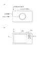
図1にデジタルスチルカメラ1の外観例を示す。図1(a)、図1(b)は、それぞれデジタルスチルカメラ1の正面図、背面図である。
このデジタルスチルカメラ1は、図1(a)に示すように、本体部2の前面側にレンズ部21aを備える。このレンズ部21aは、撮像のための光学系として本体部2の外側に表出している部位である。
FIG. 1 shows an example of the appearance of the digital
As shown in FIG. 1A, the digital
また、本体部2の上面部には、レリーズボタン31aが設けられている。撮像モード時においてはレンズ部21aにより撮像された画像(撮像画像)が画像信号として生成される。撮像モード時には、後述するイメージセンサにより所定フレームレートで各フレーム毎の撮像画像データが得られる。
そして、レリーズボタン31aに対する操作(レリーズ操作/シャッタ操作)が行われると、そのタイミングでの撮像画像(フレーム画像)が、静止画の画像データとして記録媒体に記録される。つまり、一般に写真撮影といわれる静止画撮像が行われる。
A
When an operation (release operation / shutter operation) is performed on the
また、デジタルスチルカメラ1は、図1(b)に示すように、背面側に表示画面部33aを有する。
この表示画面部33aには、撮像モード時においては、スルー画などといわれ、そのときにレンズ部21aにより撮像している画像が表示される。スルー画は、イメージセンサで得られる各フレーム画像に基づく動画像であり、そのときの被写体をそのまま表す画像となる。
また、再生モード時においては、記録媒体に記録されている画像データが再生表示される。
さらに、ユーザがデジタルスチルカメラ1に対して行った操作に応じて、GUI(Graphical User Interface)としての操作画像が表示される。
また表示画面部33aに対してタッチパネルが組み合わされているようにすることで、ユーザは、表示画面部33aに対して指を当てることによって、必要な操作を行うことができる。
The digital
This
In the reproduction mode, the image data recorded on the recording medium is reproduced and displayed.
Further, an operation image as a GUI (Graphical User Interface) is displayed according to an operation performed by the user on the digital
In addition, the touch panel is combined with the
またデジタルスチルカメラ1には、レリーズボタン31a以外の各種のキー、ダイヤル等の操作子31Bが設けられる。
例えばズーム操作、モード選択、メニュー操作、メニュー上のカーソル操作、再生操作などのための操作キーやダイヤル等である。
Further, the digital
For example, there are operation keys and dials for zoom operation, mode selection, menu operation, menu cursor operation, playback operation, and the like.
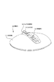
図2は雲台10の外観を示す斜視図である。また、図3〜図5は、雲台10に対してデジタルスチルカメラ1が適切な状態で載置された状態を示している。図3は正面図、図4は平面図、図5は側面図(特に図5(b)では側面図によりチルト機構の可動範囲を示している)である。
図2、及び図3,図4,図5に示すように、雲台10は、大きくは接地台部15の上に本体部11が組み合わされたうえで、さらに本体部11に対してカメラ台座部12が取り付けられた構造を有する。
FIG. 2 is a perspective view showing the external appearance of the
As shown in FIGS. 2, 3, 4, and 5, the
雲台10にデジタルスチルカメラ1を取り付けるときには、デジタルスチルカメラ1の底面側を、カメラ台座部12の上面側に置く。
図2に示すように、カメラ台座部12の上面部には、突起部13とコネクタ14が設けられている。図示は省略するが、デジタルスチルカメラ1の本体部2の下面部には、突起部13と係合する孔部が形成されている。デジタルスチルカメラ1がカメラ台座部12に対して適正に置かれた状態では、この孔部と突起部13とが係合した状態となる。この状態であれば、通常の雲台10のパンニング・チルティングの動作であれば、デジタルスチルカメラ1が雲台10からずれたり、外れてしまったりすることがないようにされている。
When the digital
As shown in FIG. 2, a projection 13 and a connector 14 are provided on the upper surface of the
また、デジタルスチルカメラ1においては、その下面部の所定位置にもコネクタが設けられている。上記のようにカメラ台座部12にデジタルスチルカメラ1が適正に取り付けられた状態では、デジタルスチルカメラ1のコネクタと雲台10のコネクタ14とが接続され、少なくとも、相互間の通信が可能な状態となる。
In the digital
なお、例えばコネクタ14と突起部13は、実際においては、カメラ台座部12においてその位置を或る範囲内で変更(移動)できるようになっている。そのうえで、例えばデジタルスチルカメラ1の底面部の形状に合わせたアダプタなどを併用することで、異なる機種のデジタルスチルカメラを、雲台10と通信可能な状態で、カメラ台座部12に取り付けできるようになっている。
For example, the position of the connector 14 and the protrusion 13 can be changed (moved) within a certain range in the
次に、雲台10によるデジタルスチルカメラ1のパン・チルト方向の基本的な動きについて説明する。
まず、パン方向の基本的な動きは次のようになる。
雲台10を例えばテーブル上や床面上などに置いた状態では、接地台部15の底面が接地する。この状態において、図4に示すように、回転軸11aを回転中心として、本体部11側が時計回り方向、及び反時計回り方向に回転できるようになっている。つまりこれにより、雲台10に取り付けられたデジタルスチルカメラ1の水平方向(左右方向)における撮像視野を変化させることができる(所謂パンニング)。
なお、この場合の雲台10のパン機構は、時計回り方向及び反時計回り方向の何れについても、360°以上の回転が無制限で自在に行える構造を有している。
Next, basic movement of the digital
First, the basic movement in the pan direction is as follows.
In a state where the
In this case, the pan mechanism of the
また、この雲台10のパン機構においては、パン方向における基準位置が決められている。
ここでは、図4に示すように、パン基準位置を0°(360°)としたうえで、パン方向に沿った本体部11の回転位置、すなわちパン位置(パン角度)を0°〜360°により表すものとする。
In the pan mechanism of the
Here, as shown in FIG. 4, the pan reference position is set to 0 ° (360 °), and the rotation position of the
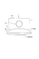
また、雲台10のチルト方向の基本的な動きについては次のようになる。
チルト方向の動きは、図5(a)(b)に示すようにして、カメラ台座部12が回転軸12aを回転中心として、仰角、俯角の両方向に角度を振ることにより得られる。
ここで、図5(a)は、カメラ台座部12がチルト基準位置Y0(0°)にある状態が示されている。この状態では、レンズ部21a(光学系部)の撮像光軸と一致する撮像方向F1と、接地台部15が接地する接地面部GRとが平行となる。
そのうえで図5(b)に示すように、先ず、仰角方向においては、カメラ台座部12は、回転軸12aを回転中心として、チルト基準位置Y0(0°)から所定の最大回転角度+f°の範囲で動くことができる。また俯角方向においても、回転軸12aを回転中心として、チルト基準位置Y0(0°)から所定の最大回転角度−g°の範囲で動くことができるようになっている。
このようにして、カメラ台座部12がチルト基準位置Y0(0°)を基点として、最大回転角度+f°〜最大回転角度−g°の範囲で動くことで、雲台10(カメラ台座部12)に取り付けられたデジタルスチルカメラ1のチルト方向(上下方向)における撮像視野を変化させることができる。つまりチルティングの動作が得られる。
The basic movement of the
As shown in FIGS. 5A and 5B, the movement in the tilt direction is obtained when the
Here, FIG. 5A shows a state in which the
In addition, as shown in FIG. 5B, first, in the elevation direction, the
In this way, the
図6は、雲台10の背面図を示している。
図示するように雲台10には、その本体部11の背面部において、電源ケーブルを着脱可能に接続する電源端子部t−Vinと、ビデオケーブルを着脱可能に接続するビデオ端子部t−Videoとが形成されている。
FIG. 6 shows a rear view of the
As shown in the figure, the
雲台10は、上述したカメラ台座部12にて取り付けられたデジタルスチルカメラ1に対して上記電源端子部t−Vinを介して入力された電力を供給することで、上記デジタルスチルカメラ1に対する充電を行うように構成されている。
つまり本例の雲台10は、デジタルスチルカメラ1に対する充電を行うためのクレードル(ドック)としても機能する。
また、本例の場合、雲台10は、デジタルスチルカメラ1側から例えば撮像画像に基づく映像信号が伝送されてきた場合に、該映像信号を上記ビデオ端子部t−Videoを介して外部出力するように構成されている。
また、この図6や先の図4にも示したように、雲台10の本体部11における背面部には、メニューボタン60aが設けられる。メニューボタンの操作により、雲台10とデジタルスチルカメラ1の間の通信により、例えばデジタルスチルカメラ1側の表示画面部33aでメニュー表示が行われる。このメニュー表示により、ユーザが所要の操作を行うことが可能とされる。
The
That is, the
In the case of this example, when a video signal based on, for example, a captured image is transmitted from the digital
As shown in FIG. 6 and FIG. 4, the
[1−2:デジタルスチルカメラ]
図7は、デジタルスチルカメラ1の内部構成例を示したブロック図である。
光学系部21は、例えばズームレンズ、フォーカスレンズなども含む所定枚数の撮像用のレンズ群、絞りなどを備えて成り、入射された光を撮像光としてイメージセンサ22の受光面に結像させる。
また、光学系部21においては、上記のズームレンズ、フォーカスレンズ、絞りなどを駆動させるための駆動機構部も備えられる。これらの駆動機構部は、例えば制御部27が実行するズーム(画角)制御、自動焦点調整制御、自動露出制御などのいわゆるカメラ制御によりその動作が制御される。
[1-2: Digital still camera]
FIG. 7 is a block diagram illustrating an internal configuration example of the digital
The
The
イメージセンサ22は、上記光学系部21にて得られる撮像光を電気信号に変換する、いわゆる光電変換を行う。このために、イメージセンサ22は、光学系部21からの撮像光を光電変換素子の受光面にて受光し、受光された光の強さに応じて蓄積される信号電荷を、所定タイミングにより順次出力する。これにより、撮像光に対応した電気信号(撮像信号)が出力される。
なお、イメージセンサ22として採用される光電変換素子(撮像素子)としては、特に限定されるものではないが、現状であれば、例えばCMOS(Complementary Metal Oxide Semiconductor)センサやCCD(Charge Coupled Device)などを挙げることができる。また、CMOSセンサを採用する場合には、イメージセンサ22に相当するデバイス(部品)として、次に述べるA/Dコンバータ23に相当するアナログ−デジタル変換器も含めた構造とすることができる。
The
The photoelectric conversion element (imaging element) employed as the
上記イメージセンサ22から出力される撮像信号は、A/Dコンバータ23に入力されることで、デジタル信号に変換され、信号処理部24に入力される。
The imaging signal output from the
信号処理部24は、例えばDSP(Digital Signal Processor)で構成され、A/Dコンバータ23から出力されるデジタル撮像信号について、プログラムに従った所定の信号処理を施す。
信号処理部24は、A/Dコンバータ23から出力されるデジタル撮像信号について、1つの静止画 (フレーム画像)に相当する単位で取り込みを行う。そして取り込んだ静止画単位の撮像信号について所定の信号処理を施すことで、1枚の静止画に相当する画像信号データである撮像画像データ(撮像静止画像データ)を生成する。
また信号処理部24は、このようにして取得した撮像画像データを利用して、後述する被写体検出処理や構図処理のための画像解析処理を実行する場合もある。
また信号処理部24は、パノラマ撮像モードの場合は、パノラマ撮像動作で得られる多数のフレーム画像を合成して、パノラマ画像データを生成する処理も行う。
The
The
In addition, the
In the case of the panoramic imaging mode, the
信号処理部24で生成した撮像画像データを記録媒体であるメモリカード40に記録させる場合には、例えば1つの静止画に対応する撮像画像データを信号処理部24からエンコード/デコード部25に対して出力する。
エンコード/デコード部25は、信号処理部24から出力されてくる静止画単位の撮像画像データについて、所定の静止画像圧縮符号化方式により圧縮符号化を実行したうえで、例えば制御部27の制御に応じてヘッダなどを付加して、所定形式に圧縮された画像データの形式に変換する。そして、このようにして生成した画像データをメディアコントローラ26に転送する。
メディアコントローラ26は、制御部27の制御に従って、メモリカード40に対して、転送されてくる画像データを書き込んで記録させる。この場合のメモリカード40は、例えば所定規格に従ったカード形式の外形形状を有し、内部には、フラッシュメモリなどの不揮発性の半導体記憶素子を備えた構成を採る記録媒体である。
なお、画像データを記録する記録媒体については、上記メモリカード以外の種別、形式などとされてもよい。例えば光ディスク、ハードディスク、着脱不能に取り付けられたフラッシュメモリチップなどの半導体メモリチップ、ホログラムメモリ等、各種の記録媒体を採用することもできる。
When the captured image data generated by the
The encoding /
The
Note that the recording medium for recording image data may be of a type or format other than the memory card. For example, various recording media such as an optical disk, a hard disk, a semiconductor memory chip such as a flash memory chip that is detachably attached, and a hologram memory may be employed.
また、デジタルスチルカメラ1は、上記信号処理部24にて得られる撮像画像データを利用して表示部33に画像表示を実行させることで、現在撮像中の画像である、いわゆるスルー画を表示させることができる。
例えば信号処理部24は、上述のようA/Dコンバータ23から出力される撮像信号を取り込んで1枚の静止画相当の撮像画像データを生成するが、この動作を継続することで、動画におけるフレーム画像に相当する撮像画像データを順次生成していく。そして、このようにして順次生成される撮像画像データを、制御部27の制御に従って表示ドライバ32に対して転送する。
Further, the digital
For example, the
表示ドライバ32は、上記のように信号処理部24から入力されてくる撮像画像データに基づいて表示部33を駆動するための駆動信号を生成し、表示部33に対して出力していく。これにより、表示部33においては、静止画単位の撮像画像データに基づく画像が順次的に表示されていく。
これをユーザが見れば、そのときに撮像している画像が表示部33において動画的に表示されることになる。つまり、スルー画が表示される。
The
If the user sees this, the image captured at that time is displayed as a moving image on the
また、デジタルスチルカメラ1は、メモリカード40に記録されている画像データを再生して、その画像を表示部33に対して表示させることも可能とされる。
このためには、制御部27が画像データを指定して、メディアコントローラ26に対してメモリカード40からのデータ読み出しを命令する。この命令に応答して、メディアコントローラ26は、指定された画像データが記録されているメモリカード40上のアドレスにアクセスしてデータ読み出しを実行し、読み出したデータを、エンコード/デコード部25に対して転送する。
The digital
For this purpose, the
エンコード/デコード部25は、例えば制御部27の制御に従って、メディアコントローラ26から転送されてきた撮像画像データから圧縮静止画データとしての実体データを取り出し、この圧縮静止画データについて、圧縮符号化に対する復号処理を実行して、1つの静止画に対応する撮像画像データを得る。そして、この撮像画像データを表示ドライバ32に対して転送する。これにより、表示部33において、メモリカード40に記録されている撮像画像データの画像が再生表示されることになる。
The encode /
また表示部33に対しては、上記のスルー画や画像データの再生画像などとともに、ユーザインターフェース画像(操作画像)も表示させることができる。
この場合には、例えばそのときの動作状態などに応じて制御部27が必要なユーザインターフェース画像としての表示用画像データを生成し、これを表示ドライバ32に対して出力する。これにより、表示部33でユーザインターフェース画像が表示される。
なお、このユーザインターフェース画像は、例えば特定のメニュー画面などのようにモニタ画像や撮像画像データの再生画像とは個別に表示部33の表示画面に表示させることも可能であるし、モニタ画像や撮像画像データの再生画像上の一部において重畳・合成されるようにして表示させることも可能である。
Further, on the
In this case, for example, the
The user interface image can be displayed on the display screen of the
制御部27は、CPU(Central Processing Unit)を備えて成るもので、ROM28、RAM29などとともにマイクロコンピュータを構成する。
ROM28には、例えば制御部27としてのCPUが実行すべきプログラムの他、デジタルスチルカメラ1の動作に関連した各種の設定情報などが記憶される。
RAM29は、CPUのための主記憶装置とされる。
また、この場合のフラッシュメモリ30は、例えばユーザ操作や動作履歴などに応じて変更(書き換え)の必要性のある各種の設定情報などを記憶させておくために使用する不揮発性の記憶領域として設けられるものである。
なおROM28について、例えばフラッシュメモリなどをはじめとする不揮発性メモリを採用することとした場合には、フラッシュメモリ30に代えて、このROM28における一部記憶領域を使用することとしてもよい。
The
The
The
Further, the
For example, if a non-volatile memory such as a flash memory is adopted as the
本実施の形態の場合、制御部27は、自動撮像のために各種の撮像準備処理を行う。
まず被写体検出処理として、撮像視野を変化させながら信号処理部24で得られる各フレーム画像から被写体検出を実行し(又は信号処理部24に実行させ)、デジタルスチルカメラ1の周囲の被写体を探索する処理を行う。
また構図処理として、被写体検出に伴い検出された被写体の態様に応じた最適とされる構図を所定アルゴリズムに従って判定する最適構図判定、及び最適構図判定により求まった最適とされる構図を目標構図とした構図合わせを行う。これらの撮像準備処理の後、制御部27は撮像画像の自動記録を実行せる制御・処理を行う。
また制御部27は、パノラマ撮像のための処理、即ちパノラマ撮像としての多数のフレーム画像の撮像や合成処理の指示を行ったり、パノラマ撮像モードにおけるパラメータ設定などの処理も行う。さらに雲台10に装着されている場合は、雲台10にパノラマ撮像のための略水平方向の回転移動を実行させる制御も行う。
これらの制御処理については後述する。
In the case of the present embodiment, the
First, as subject detection processing, subject detection is performed from each frame image obtained by the
In addition, as composition processing, the optimal composition determination according to a predetermined algorithm for determining the optimal composition according to the form of the subject detected upon subject detection, and the optimal composition obtained by the optimal composition determination as the target composition Perform composition adjustment. After these imaging preparation processes, the
In addition, the
These control processes will be described later.
操作部31は、デジタルスチルカメラ1に備えられる各種操作子と、これらの操作子に対して行われた操作に応じた操作情報信号を生成して制御部27に出力する操作情報信号出力部位とを一括して示している。
操作子としては、図1に示したレリーズボタン31aや各種の操作子31b(電源ボタン、モードボタン、ズーム操作ボタン、操作ダイヤル等)がある。
また表示部33がタッチパネルとして形成される場合、そのタッチセンサ部も、この操作部31の具体例の1つとなる。
さらに、リモートコントローラからのコマンド信号の受信部も、操作部31の例の一つとなる。
制御部27は、操作部31から入力される操作情報信号に応じて所定の処理を実行する。これによりユーザ操作に応じたデジタルスチルカメラ1の動作が実行されることになる。
The
As the operation elements, there are the
When the
Further, a command signal receiving unit from the remote controller is one example of the
The
雲台対応通信部34は、雲台10側とデジタルスチルカメラ1側との間での所定の通信方式に従った通信を実行する部位である。
例えばデジタルスチルカメラ1が雲台10に取り付けられた状態において、雲台10側の通信部との間で通信信号の送受信を可能とするための物理層構成と、これより上位となる所定層に対応する通信処理を実現するための構成とを有して成る。上記物理層構成として、図2との対応では、コネクタ14と接続されるコネクタの部位が含まれる。
The pan head
For example, in a state where the digital
また雲台10側からの充電を可能とすべく、上記の各コネクタには通信信号のやり取りを行うための端子のみでなく充電用電力の伝送のための端子も設けられる。図示は省略したが、デジタルスチルカメラ1には、バッテリーを着脱可能に装着するためのバッテリー装着部が設けられており、該装着部に装着されたバッテリーに対し、雲台10側から伝送された電力に基づく充電が行われるようになっている。
Further, in order to enable charging from the
移動検出部35は、デジタルスチルカメラ1の本体の移動状況を検出するセンサ部とされる。例えば加速度センサ、角速度センサ、ジャイロセンサなどが設けられる。
パノラマ撮像の場合には、デジタルスチルカメラ1の移動速度が制限される場合がある。デジタルスチルカメラ1の移動速度は、移動検出部35によって検出され、制御部27に供給される。これによって制御部27は、移動速度が制限範囲内であるか否かを判別できる。また移動速度と時間からパノラマ撮像時の角度範囲も算出できる。
The
In the case of panoramic imaging, the moving speed of the digital
[1−3:雲台]
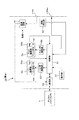
図8は、雲台10の内部構成例を示している。
先の図6に示したように、雲台10には電源端子部t−Vinとビデオ端子部t−Videoとが設けられている。
電源端子部t−Vinを介して入力された電力は、電源回路61を介した後、雲台10内の必要な各部の動作電力として供給される。また、電源回路61においては、デジタルスチルカメラ1に対する充電用電力が生成され、該充電用電力は通信部52(コネクタ)を介してデジタルスチルカメラ1側に供給される。
また、上記ビデオ端子部t−Videoには、デジタルスチルカメラ1側から伝送された映像信号が通信部52→制御部51を介して供給される。
[1-3: pan head]
FIG. 8 shows an example of the internal configuration of the
As shown in FIG. 6, the
The electric power input through the power supply terminal unit t-Vin is supplied as operating power for each necessary unit in the pan /
Further, the video signal transmitted from the digital
なお、ここでは、雲台10の各部の動作電力は上記電源入力端子t−Vinを介してのみ供給されるかのように示しているが、実際には雲台10には、電池の装着部が設けられ、該装着部に装着された電池から各部の動作電力を供給することが可能に構成されている。
Here, the operating power of each part of the
また雲台10には、上記電源端子部t−Vin、上記ビデオ端子部t−Videoへのケーブルの接続有無を検出するための接続検出部59が設けられる。ケーブル接続有無の検出機構の具体的な構成については、例えばケーブルの接続/抜き取りに応じてスイッチがON/OFFする構成などを挙げることができる。但し接続検出部59としては、ケーブルの接続/抜き取りを識別するための検出信号を出力するように構成されたものであればよく、その具体的な構成については特に限定されない。
接続検出部59による検出信号(電源端子部t−Vinについての検出信号とビデオ端子部t−Videoについての検出信号)は、制御部51に対して供給される。
Further, the
Detection signals from the connection detection unit 59 (a detection signal for the power supply terminal unit t-Vin and a detection signal for the video terminal unit t-Video) are supplied to the
また雲台10は、先に述べたようにパン・チルト機構を備えるものであり、これに対応する部位として、図8にパン機構部53、パン用モータ54、チルト機構部56、チルト用モータ57を示している。
パン機構部53は、雲台10に取り付けられたデジタルスチルカメラ1について、図4に示したパン(横・左右)方向の動きを与えるための機構を有して構成され、この機構の動きは、パン用モータ54が正逆方向に回転することによって得られる。
同様にして、チルト機構部56は、雲台10に取り付けられたデジタルスチルカメラ1について、図5に示したチルト(縦・上下)方向の動きを与えるための機構を有して構成され、この機構の動きは、チルト用モータ57が正逆方向に回転することによって得られる。
The
The
Similarly, the
制御部51は、例えばCPU、ROM、RAMなどが組み合わされて形成されるマイクロコンピュータによって成り、パン機構部53、チルト機構部56の動きをコントロールする。
例えば制御部51がパン機構部53の動きを制御するときには、移動させるべき方向と移動速度を指示する信号をパン用駆動部55に対して出力する。パン用駆動部55は、入力される信号に対応したモータ駆動信号を生成してパン用モータ54に出力する。このモータ駆動信号は、例えばモータがステッピングモータであれば、PWM制御に対応したパルス信号となる。
このモータ駆動信号により、パン用モータ54が例えば所要の回転方向、回転速度により回転し、この結果、パン機構部53も、これに対応した移動方向と移動速度により動くように駆動される。
同様に、チルト機構部56の動きを制御するときには、制御部51は、チルト機構部56に必要な移動方向、移動速度を指示する信号をチルト用駆動部58に対して出力する。チルト用駆動部58は、入力される信号に対応したモータ駆動信号を生成してチルト用モータ57に出力する。このモータ駆動信号によりチルト用モータ57が、例えば所要の回転方向及び回転速度で回転し、この結果、チルト機構部56も、これに対応した移動方向,速度により動くように駆動される。
The
For example, when the
By this motor drive signal, the
Similarly, when controlling the movement of the
ここで、パン機構部53は、ロータリーエンコーダ(回転検出器)53aを備えている。ロータリーエンコーダ53aは、パン機構部53の回転の動きに応じて、その回転角度量を示す検出信号を制御部51に出力する。同様に、チルト機構部56はロータリーエンコーダ56aを備える。このロータリーエンコーダ56aも、チルト機構部56の回転の動きに応じて、その回転角度量を示す信号を制御部51に出力する。
これにより制御部51は、駆動中のパン機構部53、チルト機構部56の回転角度量の情報をリアルタイムに取得(モニタ)できるようにされている。
Here, the
As a result, the
通信部52は、雲台10に取り付けられたデジタルスチルカメラ1内の雲台対応通信部34との間で所定の通信方式に従った通信を実行する部位である。
この通信部52は、雲台対応通信部34と同様に、相手側通信部と有線若しくは無線による通信信号の送受信を可能とするための物理層構成と、これより上位となる所定層に対応する通信処理を実現するための構成とを有して成る。上記物理層構成として、図2との対応では、カメラ台座部12のコネクタ14が含まれる。
The
The
操作部60は、具体的には、先の図4や図6に示したメニューボタン60aとしての操作子と、この操作子に対して行われた操作に応じた操作情報信号を生成して制御部51に出力する操作情報信号出力部位とを一括して示している。制御部51は、操作部60から入力される操作情報信号に応じて所定の処理を実行する。
なお、雲台10についてリモートコントローラが用意される場合は、そのリモートコントローラからのコマンド信号の受信部も、操作部60の例の一つとなる。
Specifically, the
When a remote controller is prepared for the
<2.機能構成例>
次に、図9のブロック図により、本実施の形態のデジタルスチルカメラ1及び雲台10についての、ハードウェア及びソフトウェア(プログラム)により実現される機能構成例を示す。
この機能構成例は、本例の撮像システムの撮像動作制御を行う撮像制御装置を実現する構成となり、主に、デジタルスチルカメラ1における制御部27、雲台10における制御部51等のハードウエア構成と、それらで起動されたソフトウエアモジュールが連関して形成される制御処理機能である。
但し図9では、特に後述するパノラマ撮像モード処理、自動静止画撮像モード処理のために必要な制御機能を、機能毎にブロック化して示している。
<2. Functional configuration example>
Next, the block diagram of FIG. 9 shows a functional configuration example realized by hardware and software (program) for the digital
This functional configuration example is a configuration that realizes an imaging control device that performs imaging operation control of the imaging system of the present example. And a control processing function formed by linking software modules activated by them.
However, in FIG. 9, control functions necessary for panoramic imaging mode processing and automatic still image imaging mode processing, which will be described later, are shown in blocks for each function.
図9に示すように、デジタルスチルカメラ1(制御部27)側は、撮像記録制御部81、撮像準備処理部82、撮像視野可変制御部83、パノラマ撮像制御部84、通信処理部85、装着判定部86を備える。
また雲台10(制御部51)側は、例えば通信処理部71、パン・チルト制御部72を有している。
As shown in FIG. 9, on the digital still camera 1 (control unit 27) side, an imaging
The pan head 10 (control unit 51) side includes, for example, a
まずデジタルスチルカメラ1側において、撮像記録制御部81は、撮像により得られた画像を画像信号のデータ(撮像画像データ)として得て、この撮像画像データを記録媒体に記憶するための制御処理を実行する部位である。また撮像記録制御部81は、記録した静止画データの再生、表示動作、或いは撮像時のスルー画の表示動作等のための制御も行う。
即ち撮像記録制御部81は、図7の光学系部21、イメージセンサ22、A/Dコンバータ23、シング処理部24、エンコード/デコード部25、メディアコントローラ26、表示ドライバ32等の制御を行う。即ち、光学系部21のレンズ駆動制御、イメージセンサ22の撮像動作、撮像信号処理、記録再生処理等を指示し、静止画撮像を実行させるなど、デジタルスチルカメラ1の基本動作を制御する機能部位である。
First, on the digital
That is, the imaging /
撮像準備処理部82は、ユーザのレリーズ操作によらない自動的な静止画撮像(後述する自動静止画撮像モードの撮像)を実行する際の撮像準備処理を行う機能部位である。
撮像準備処理の1つとしては被写体検出処理がある。これは、雲台10によるパン、チルト動作を実行させながら、信号処理部24で得られる各フレーム画像を確認し、撮像視野内に被写体(例えば人の顔)が入るようにする処理である。このために、撮像準備処理部82は、必要な雲台10のパン・チルト動作の判断や、フレーム画像データの画像解析による人物検出、顔検出等の処理を行う。
また撮像準備処理の1つとして構図処理がある。構図処理とは、撮像視野内における被写体画像の配置について最適状態か否かを判断し(構図判定)、またその構図を調整する処理(構図合わせ)である。この構図の調整のために撮像準備処理部82は、必要な雲台10のパン・チルト動作の判断や、光学系部21におけるズームレンズ駆動の判断等を行う。
The imaging
One of the imaging preparation processing is subject detection processing. This is a process of confirming each frame image obtained by the
There is a composition process as one of the imaging preparation processes. The composition processing is processing for determining whether or not the arrangement of the subject image in the imaging field of view is in an optimal state (composition determination) and adjusting the composition (composition adjustment). In order to adjust the composition, the imaging
なお、上記の被写体検出処理や構図処理のための画像解析を行う処理機能は、制御部27ではなく信号処理部24としてのDSP(Digital signal Processor)に実行させることもできる。従って撮像準備処理部82としての機能部は、制御部27、信号処理部24としてのDSPの一方又は両方に与えるプログラム、インストラクションにより実現できる。
Note that the processing function for performing image analysis for subject detection processing and composition processing described above can be executed not by the
撮像視野可変制御部83は、実際に撮像視野を変化させる動作を制御する機能部位である。撮像視野の変化は、雲台10のパン・チルト、もしくは光学系部21のズーム動作により行われる。従って撮像視野可変制御部83は、パン・チルト制御、ズーム制御を行う機能部位となる。
デジタルスチルカメラ1を用いてカメラマンが手動で撮像を行う場合は、撮像視野可変制御部83は、例えばカメラマンのズーム操作に応じてズームレンズ駆動を制御することとなる。
また自動的な静止画撮像や、雲台10に装着した状態でパノラマ撮像を行う場合、撮像視野可変制御部83は、撮像準備処理部82の判断・指示、又はパノラマ撮像制御部84からの指示に応じて、ズーム駆動制御、パン駆動制御、チルト駆動制御を行う。
パン駆動制御、チルト駆動制御については、通信処理部85を介して雲台10側にパン・チルト制御信号を送信することになる。
例えば撮像視野可変制御部83は、構図合わせ等の実行時には、撮像準備処理部82が判定するパン・チルトの移動量に応じて、雲台10に当該移動量を指示するパン・チルト制御信号を出力する。
また撮像視野可変制御部83は、撮像準備処理部82で判定されるズーム倍率に応じて、光学系部21のズーム動作を駆動制御する。
また撮像視野可変制御部83は、雲台10に装着した状態でパノラマ撮像を行う場合は、パノラマ撮像における略水平方向の回転移動を実行するため、主にパン動作を指示するパン・チルト制御信号を、通信処理部85を介して雲台10側に送信する。
The imaging field
When the cameraman manually captures an image using the digital
When performing automatic still image capturing or panoramic imaging while mounted on the
For pan drive control and tilt drive control, a pan / tilt control signal is transmitted to the
For example, the imaging visual field
Further, the imaging field
In addition, when performing panoramic imaging with the pan /
通信処理部85は、雲台10側に備えられる通信処理部71との間で所定の通信プロトコルに従って通信を実行するための部位となる。
上記の撮像視野可変制御部83が生成したパン・チルト制御信号は、通信処理部64の通信により、雲台10の通信処理部71に対して送信される。
The
The pan / tilt control signal generated by the imaging field
装着判定部86は、デジタルスチルカメラ1が雲台10に装着されているか否かの判定を行う。
例えば通信処理部85を介して雲台10の通信処理部71(制御部51)との間で、所定の機器認識のための通信を実行させる。この通信により所定の機器として雲台10が認識できたら、当該デジタルスチルカメラ1が雲台10に装着されていると判定する。
なお本例では、雲台10を、デジタルスチルカメラ1本体を略水平方向に回転可能に保持する所定種別の回転台として位置づけ、雲台10への装着状態を判別するものである。これは、デジタルスチルカメラ1が安定回転可能状態とされているか否かを検出する一手法となる。
The mounting
For example, communication for predetermined device recognition is executed with the communication processing unit 71 (control unit 51) of the
In this example, the
なお本発明請求項との関係を言及すると、次のようになる。
本実施の形態においては、図7の光学系部21、イメージセンサ22、A/Dコンバータ23、信号処理部24が本発明請求項における撮像部に相当する。
またエンコード/デコード部25、メディアコントローラ26が本発明請求項における記録部に相当する。
また、図9における装着判定部86(制御部27)が本発明請求項における安定回転可能状態検出部に相当する。
また、図9におけるパノラマ撮像制御部84(制御部27)が、本発明請求項における制御部に相当する。
The relationship with the claims of the present invention is as follows.
In the present embodiment, the
The encode /
Moreover, the mounting determination part 86 (control part 27) in FIG. 9 is equivalent to the stable rotation possible state detection part in this invention claim.
Further, the panorama imaging control unit 84 (control unit 27) in FIG. 9 corresponds to the control unit in the claims of the present invention.
次に図9の機能構成における雲台10側において、通信処理部71は、デジタルスチルカメラ1側の通信処理部85との間での通信を実行するための部位である。
上記のパン・チルト制御信号を受信した場合には、このパン・チルト制御信号をパン・チルト制御部72に出力する。
Next, on the
When the pan / tilt control signal is received, the pan / tilt control signal is output to the pan /
パン・チルト制御部72は、例えば図8に示した雲台10側の制御部51が実行する制御処理のうちで、パン・チルト制御に関する処理の実行機能となる。
このパン・チルト制御部72は、入力したパン・チルト制御信号に応じて、図8に示したパン用駆動部55、チルト用駆動部58を制御する。これにより、例えばパノラマ撮像や被写体検出処理のためのパンニング、チルティングや、構図処理による、最適な水平視野角と垂直視野角を得るためのパンニング、チルティング等が行われる。
The pan /
The pan /
なお、図9では、各制御機能部位をブロック化して示しているが、これらがそれぞれ独立したプログラムモジュール、或いはハードウエアとして構成される必要はない。事実上、これらの制御機能部の総合的な処理として、以降説明していく処理動作が実現されるものであればよい。
In FIG. 9, each control function part is shown as a block, but these do not have to be configured as independent program modules or hardware. In fact, any processing operation that will be described below may be realized as the overall processing of these control function units.
<3.自動静止画撮像モード処理>
ここでは、デジタルスチルカメラ1が雲台10に装着された状態で可能となる自動静止画撮像モードの動作について説明する。
図10は、ユーザのレリーズ操作を伴わない自動的な静止画撮像処理の手順を示している。
自動静止画撮像を行う自動静止画撮像モードでは、本例の撮像システムが、撮像準備として、被写体検出(探索)、最適構図判定、構図合わせの各動作により、被写体検出で検出された被写体の態様に応じて判定した最適とされる構図を目標構図とした自動構図合わせ動作を行う。そして所定の条件で自動的にレリーズ処理を行う。これにより、カメラマンの操作を不要として、適切な静止画撮像が行われるものである。
<3. Automatic still image capture mode processing>
Here, the operation in the automatic still image capturing mode that is possible when the digital
FIG. 10 shows a procedure for automatic still image capturing processing that does not involve the user's release operation.
In the automatic still image capture mode that performs automatic still image capture, the imaging system of this example prepares for imaging, and the subject mode detected by subject detection by subject detection (search), optimum composition determination, and composition adjustment operations The automatic composition adjustment operation is performed with the optimum composition determined according to the target composition as the target composition. Then, release processing is automatically performed under predetermined conditions. As a result, appropriate still image capturing is performed without requiring the operation of the cameraman.
自動静止画撮像モードでの撮像動作が開始されると、図10のステップF1として、撮像画像データの取り込みが開始される。
即ち撮像記録制御部81が、イメージセンサ22、信号処理部24による撮像画像データの各フレーム毎の取り込みを開始させる。
When the imaging operation in the automatic still image imaging mode is started, capturing of captured image data is started as Step F1 in FIG.
That is, the imaging
ステップF2で被写体検出処理、ステップF3で構図処理を行う。
被写体検出処理、構図処理(最適構図判定、構図合わせ)は、撮像準備処理部82の機能(具体的には制御部27、及び/又は信号処理部24の処理)により実行される。
Subject detection processing is performed in step F2, and composition processing is performed in step F3.
Subject detection processing and composition processing (optimum composition determination, composition adjustment) are executed by the function of the imaging preparation processing unit 82 (specifically, the processing of the
ステップF1で撮像画像データの取り込みが開始された以降は、信号処理部24は、イメージセンサ22による撮像画像データとして、1枚の静止画に相当するフレーム画像データを順次取得する。
撮像準備処理部82は、被写体検出処理として、各フレーム画像データから、人物の顔に相当する画像部分を検出する処理を行う。
なお、被写体検出処理は、全フレーム毎に実行しても良いし、予め定められた所定のフレーム数間隔ごとに実行してもよい。
After the capturing of the captured image data is started in step F1, the
The imaging
The subject detection process may be executed for every frame, or may be executed for every predetermined number of frames.
本例の場合における被写体検出処理では、例えばいわゆる顔検出技術を利用して、画像内から検出した被写体ごとにその顔の画像部分の領域に対応して顔枠を設定する。その上で、当該顔枠の数、サイズ、位置など情報から、画枠内における被写体数、各被写体のサイズやそれぞれの画枠内での位置の情報を得る。
なお、顔検出の手法についてはいくつか知られているが、本実施の形態において、どのような検出手法を採用するのかについては特に限定されるべきものではなく、検出精度や設計難易度などを考慮して適宜適切とされる方式が採用されるようにすればよい。
In the subject detection process in this example, a face frame is set for each subject detected from within the image, for example, using a so-called face detection technique, corresponding to the area of the image portion of the face. Then, information on the number of subjects in the image frame, the size of each subject, and the position in each image frame is obtained from information such as the number, size, and position of the face frame.
Note that some face detection methods are known, but in the present embodiment, what kind of detection method is adopted is not particularly limited, and detection accuracy, design difficulty, etc. A method that is appropriately appropriate in consideration may be adopted.
ステップF2での被写体検出処理としては、先ずはデジタルスチルカメラ1の周囲に存在する被写体の探索を行う。
具体的に、この被写体の探索としては、デジタルスチルカメラ1における制御部27(撮像準備処理部82、撮像視野可変制御部83)が、雲台10に対するパン・チルト制御や光学系部21に対するズーム制御を行うことによって、撮像視野を変化させながら、例えば信号処理部24(又は制御部27)での画像解析による被写体検出を実行させること行う。
このような被写体探索は、撮像画像データとしてのフレーム画像に被写体が検出されるまで実行される。そしてフレーム画像内、つまりその時点の撮像視野に被写体(人物の顔)が存在する状態が得られたことに応じて終了する。
As the subject detection process in step F2, first, a search for subjects existing around the digital
Specifically, as the search for the subject, the control unit 27 (the imaging
Such subject search is executed until a subject is detected in a frame image as captured image data. Then, the process ends when a subject (person's face) is present in the frame image, that is, in the imaging field of view at that time.
被写体検出処理が終了した後、制御部27(撮像準備処理部82)は、ステップF3で構図処理を行う。
構図処理としては、まずその時点の構図が最適な状態か否かを判定する。この場合、被写体検出結果に基づく画構造の判定(この場合は画枠内における被写体数、被写体サイズ、被写体位置の判定など)を行った上で、該画構造判定により判定した画構造の情報に基づき、所定アルゴリズムに従って最適とされる構図を判定する。
ここで、この場合の構図は、パン・チルト・ズームの各撮像視野によって決定づけられるものであり、従って当該最適な構図か否かの判定処理によっては、その判定結果として、上記被写体検出結果(画枠内での被写体の態様)に応じた最適な撮像視野とするためのパン・チルト・ズームの制御量の情報が得られるものとなる。
After the subject detection processing is completed, the control unit 27 (imaging preparation processing unit 82) performs composition processing in step F3.
As composition processing, it is first determined whether or not the composition at that time is in an optimal state. In this case, after determining the image structure based on the subject detection result (in this case, determination of the number of subjects, the subject size, the subject position, etc. in the image frame), the information on the image structure determined by the image structure determination is added. Based on this, an optimum composition is determined according to a predetermined algorithm.
Here, the composition in this case is determined by each of the pan, tilt, and zoom imaging fields of view. Therefore, depending on the determination process of whether or not the composition is the optimal composition, the subject detection result (image Information on the amount of control of pan / tilt / zoom for obtaining an optimal imaging field of view according to the aspect of the subject within the frame can be obtained.
そして構図が最適な状態でなければ、構図合わせとして、最適な構図状態とすべく、パン・チルト制御、ズーム制御を行うこととなる。
具体的に制御部27(撮像準備処理部82、撮像視野可変制御部83)は、構図合わせ制御として、最適構図判定処理により求まったパン・チルトの各制御量の変更の情報を雲台10側の制御部51に指示する。
これに応じて雲台10の制御部51は、指示された制御量に応じたパン機構部53・チルト機構部56についての移動量を求め、この求めた移動量のパン駆動、チルト駆動が行われるように、パン用駆動部55、チルト用駆動部58に対する制御信号の供給を行う。
また、制御部27(撮像準備処理部82、撮像視野可変制御部83)は、最適構図判定処理により求まったズームについての画角の情報を、光学系部21に指示することで、該指示した画角が得られるように光学系部21によるズーム動作を実行させる。
If the composition is not in an optimal state, pan / tilt control and zoom control are performed to achieve the optimal composition state as composition adjustment.
Specifically, the control unit 27 (the imaging
In response to this, the
In addition, the control unit 27 (the imaging
なお、構図処理で最適構図の状態ではないと判断され、構図合わせとして、パン・チルト、ズーム制御を行った場合は、ステップF2の被写体検出処理からやり直す。パン・チルト、ズーム動作により、或いは人物の動きにより、被写体が撮像視野から外れることもあるためである。 If it is determined that the composition is not in the optimum composition state and pan / tilt and zoom control is performed as composition adjustment, the process is repeated from the subject detection process in step F2. This is because the subject may deviate from the imaging field of view due to pan / tilt and zoom operations or due to the movement of a person.
制御部27(撮像記録制御部81)は、最適な構図が得られた場合は、ステップF4でレリーズタイミング判定処理を行う。
なお、ステップF4によるレリーズタイミング判定処理にてレリーズタイミングがOKとならない場合も有り得るが、その場合、ステップF1の被写体検出からやり直すことになる。被写体人物の動き等により被写体が撮像視野から外れたり、或いは構図が崩れる場合があるためである。
When the optimal composition is obtained, the control unit 27 (imaging / recording control unit 81) performs a release timing determination process in step F4.
There may be a case where the release timing is not OK in the release timing determination process in step F4, but in this case, the process starts again from the subject detection in step F1. This is because the subject may be out of the imaging field of view or the composition may be lost due to the movement of the subject person.
レリーズタイミング判定処理によってレリーズ条件が成立したとされた場合は、ステップF5のレリーズ処理として、撮像画像データの自動記録を行う。具体的に制御部27(撮像記録制御部81)は、エンコード/デコード部25及びメディアコントローラ26に対する制御を行って、その時点で得られている撮像画像データ(フレーム画像)のメモリカード40への記録を実行させる。
If it is determined that the release condition is satisfied by the release timing determination process, the captured image data is automatically recorded as the release process in step F5. Specifically, the control unit 27 (imaging / recording control unit 81) controls the encoding /
ところで、ステップF4におけるレリーズタイミング判定処理とは、適切な静止画を得るため、所定の静止画撮像条件を満たしたか否かを判定する処理であるが、各種の例が考えられる。
例えば時間によるレリーズタイミング判定が考えられる。例えば構図処理がOKとなった時点から所定時間(例えば2,3秒)の経過を静止画撮像条件とする。その場合、制御部27(撮像記録制御部81)は、ステップF4では所定時間のカウントを行い、所定時間経過により、ステップF5でレリーズ処理を実行させる。
Incidentally, the release timing determination process in step F4 is a process for determining whether or not a predetermined still image capturing condition is satisfied in order to obtain an appropriate still image, but various examples are conceivable.
For example, release timing determination by time can be considered. For example, the elapse of a predetermined time (for example, a few seconds) from the time when the composition process becomes OK is set as a still image capturing condition. In this case, the control unit 27 (imaging / recording control unit 81) counts a predetermined time in step F4, and causes the release process to be executed in step F5 when the predetermined time elapses.
また撮像画像から特定の被写体状態が判定されたときに、静止画撮像条件を満たしたと判断してもよい。
制御部27(撮像記録制御部81)は、ステップF4で、撮像画像の解析により検出される特定の被写体状態の有無を監視する。
特定の被写体状態とは、構図処理で捉えている被写体が笑顔になるなど、特定の表情となったことや、特定のジェスチャ、例えば撮像システムに向かって手を振る、手を挙げる、手を叩く、ピースサインをする、撮像システムに向かってウインクするなどの挙動を行った状態が考えられる。或いは、被写体となっているユーザが撮像システムを注視するなども考えられる。
制御部27はステップF4で、撮像画像の画像解析処理により、これらユーザの特定の状態を判定する。そして特定の被写体状態が検出されたら、レリーズタイミングとなったとして、ステップF5でレリーズ処理を実行させる。
Further, when a specific subject state is determined from the captured image, it may be determined that the still image capturing condition is satisfied.
In step F4, the control unit 27 (imaging record control unit 81) monitors the presence or absence of a specific subject state detected by analyzing the captured image.
The specific subject state means that the subject captured in the composition process has become a smile, such as a specific facial expression, a specific gesture, such as waving at the imaging system, raising the hand, or clapping the hand A state in which a behavior such as peace signing or winking toward the imaging system is performed can be considered. Alternatively, the user who is the subject may be gazing at the imaging system.
In step F4, the
またデジタルスチルカメラ1が音声入力部を備えるようにし、特定の音声入力があったときに、静止画撮像条件を満たしたと判断してもよい。
例えばユーザの発する特定の言葉、手を叩く音、口笛の音などを静止画撮像条件としての特定の音とする。制御部27(撮像記録制御部81)は、ステップF4で、これらの特定の音の入力検出を行う。
上記音声入力部からの入力音声信号解析結果から、これらの特定の音が確認されたら、レリーズタイミングとなったとして、ステップF5でレリーズ処理を実行させる。
Further, the digital
For example, a specific word generated by the user, a clapping sound, a whistling sound, or the like is set as a specific sound as a still image capturing condition. The control unit 27 (imaging / recording control unit 81) detects the input of these specific sounds in step F4.
When these specific sounds are confirmed from the input sound signal analysis result from the sound input unit, the release process is executed in step F5, assuming that the release timing has come.
以上の図10のように、制御部27による制御・処理に基づき、自動静止画撮像モードでの静止画撮像が実現される。
As shown in FIG. 10 described above, still image capturing in the automatic still image capturing mode is realized based on the control and processing by the
<4.パノラマ撮像モード処理>
続いてパノラマ撮像モード処理について説明する。
本実施の形態のデジタルスチルカメラ1は、上記のように雲台10に装着されることで自動静止画撮像モードでの撮像が実行されるが、雲台10に装着されない単体でも、また雲台10に装着された状態でも、パノラマ撮像モードでの撮像が可能とされる。
<4. Panorama imaging mode processing>
Next, the panorama imaging mode process will be described.
The digital
まずパノラマ撮像の概要を図11に示す。
例えば図11(a)は、デジタルスチルカメラ1の位置を中心としての周囲360度の光景であるとする。パノラマ撮像では、このような周囲の光景を広い範囲で一枚の画像として得る動作である。
First, an overview of panoramic imaging is shown in FIG.
For example, FIG. 11A is a scene of 360 degrees around the position of the digital
デジタルスチルカメラ1の処理としては次のようになる。
例えばユーザがデジタルスチルカメラ1を手に持ってパノラマ撮像を行う場合、ユーザは所定の撮像実行の操作状態(一例としてレリーズボタン31aを押したまま)で、デジタルスチルカメラ1の被写体方向(撮像視野)が水平に移動させていく。例えば自分を中心にしてデジタルスチルカメラ1を回転移動させることで、デジタルスチルカメラ1の画枠に入る光景を例えば左から右へと移動させていく。
この過程でデジタルスチルカメラ1は、例えば図11(b)のフレームF1、F2、F3・・・Fnとして示すように、所定フレーム間隔毎で撮像されるフレーム画像データを取り込んでいく。
そして、各フレーム画像データF1〜Fnのそれぞれの必要領域を用いて合成処理を行う。ここでは合成処理の詳細については詳述を避けるが、結果として複数のフレーム画像データとして撮像された画像をつなぎ合わせる処理となる。そして、例えば図11(c)のようなパノラマ画像データを生成し、これを1枚のパノラマ画像データとしてメモリカード40に記録する。
The processing of the digital
For example, when a user performs panoramic imaging with the digital
In this process, the digital
Then, a synthesis process is performed using each necessary area of each of the frame image data F1 to Fn. Here, the details of the synthesis process are not described in detail, but as a result, the process is a process of stitching together images captured as a plurality of frame image data. Then, for example, panoramic image data as shown in FIG. 11C is generated and recorded in the
このようなパノラマ撮像モードでの撮像を実行するための制御部27の処理を図12に示す。
ユーザが所定の操作によりパノラマ撮像モードとした場合、制御部27は図12の処理を開始する。
まずステップF101で制御部27(装着判定部86)は、当該デジタルスチルカメラ1が雲台10に装着されているか否かを判定する。例えば上述のように装着判定部86は通信処理部85からの雲台10への機器認識のための通信を試みる。そして雲台10との通信が確立でき、通信先が本例における雲台10と確認できた場合、現在デジタルスチルカメラ1は安定回転可能状態であると判別する。
一方、雲台10との通信が不能である場合は、装着判定部86は、ユーザがデジタルスチルカメラ1を手に持った状態でパノラマ撮像を行おうとしている場合であると判定する。
FIG. 12 shows the processing of the
When the user enters the panoramic imaging mode by a predetermined operation, the
First, in step F101, the control unit 27 (mounting determination unit 86) determines whether or not the digital
On the other hand, if communication with the
安定回転可能状態であると判別した場合、制御部27は処理をステップF110に進め、一方、ユーザが手持ちでパノラマ撮像を行うと判別した場合は、処理をステップF103に進める。
まず手持ちと判定した場合について説明する。
この場合、制御部27(パノラマ撮像制御部84)はステップF103で、手持ち撮像用のパラメータ設定を行う。
例を挙げる。
If it is determined that the stable rotation is possible, the
First, a case where it is determined that the hand is held will be described.
In this case, the control unit 27 (panoramic imaging control unit 84) sets parameters for handheld imaging in step F103.
Give an example.
例えば角度制限としてパノラマ撮像を行う角度範囲を所定角度範囲に制限する設定を行う。例えば0度〜270度を撮像可能な角度範囲とするパラメータ設定を行う。
このような設定を行うのは、手持ちの場合、0度のフレーム画像データと360度のフレーム画像データでの画像の繋ぎ目で上下のずれが発生することが殆どであり、高品質なパノラマ画像データの生成が困難であるため、360度の範囲の撮像は実行させないとするものである。また、あまりに広角であると、ユーザによる水平移動過程の上下方向のズレが大きくなるということもある。
For example, the angle range for panoramic imaging is set to be limited to a predetermined angle range as the angle limit. For example, parameter setting is performed so that an angle range from 0 degrees to 270 degrees can be captured.
Such a setting is mostly performed when there is a hand-held image, and vertical misalignment occurs at the joint between the 0-degree frame image data and the 360-degree frame image data. Since it is difficult to generate data, imaging in the range of 360 degrees is not executed. Also, if the angle is too wide, the vertical shift in the horizontal movement process by the user may increase.
また、速度制限として、パノラマ撮像時の許容速度範囲の所定の速度範囲に制限する設定を行う。例えば20°/sec〜100°/secを許容速度範囲とするパラメータ設定を行う。
これは、ユーザがデジタルスチルカメラ1を水平に回転移動させる場合に、移動させる速度が速すぎても遅すぎてもブレが大きくなり、合成処理が困難となるとともに、高品位なパノラマ画像データが生成できなくなるためである。
Also, as a speed limit, a setting is made to limit to a predetermined speed range of an allowable speed range at the time of panoramic imaging. For example, parameter setting is performed so that the allowable speed range is 20 ° / sec to 100 ° / sec.
This is because when the user rotates and moves the digital
また、ズーム制限として、パノラマ撮像時のズーム動作を制限する設定を行う。例えばズーム禁止とし、所定のズーム角に固定する設定を行う。或いは、ズームは2倍までという制限を設けた設定を行う。
ズーム倍率を上げると、それだけ撮像視野が狭くなるため、ユーザの移動時の上下方向のブレやずれが画像上に顕著に表れる。従って、高いズーム倍率でパノラマ撮像を実行させると、合成処理が困難となるとともに、高品位なパノラマ画像データが生成できなくなるためである。
In addition, as a zoom restriction, a setting for restricting a zoom operation at the time of panoramic imaging is performed. For example, the zoom is prohibited and the setting is fixed to a predetermined zoom angle. Alternatively, the zoom is set with a limit of up to 2 ×.
When the zoom magnification is increased, the imaging field of view is narrowed accordingly, so that vertical blurring and shifting during the movement of the user appears remarkably on the image. Therefore, if panoramic imaging is executed at a high zoom magnification, the composition process becomes difficult and high-quality panoramic image data cannot be generated.
また解像度設定として、解像度を所定値に制限する設定を行う。例えばピクセル数で言えば、一例として5000×1000ピクセルに制限するなどとする設定である。
これもユーザの手持ちによりデジタルスチルカメラ1を移動させる場合のブレ等の不安定さを考慮した設定である。
As the resolution setting, a setting for limiting the resolution to a predetermined value is performed. For example, in terms of the number of pixels, the setting is limited to, for example, 5000 × 1000 pixels.
This is also a setting in consideration of instability such as blurring when the digital
制御部27(パノラマ撮像制御部84)はステップF103で、例えばこれらの全部又は一部の設定を行う。もちろん設定例は他にも考えられる。
そしてステップF104で撮像開始を待機する。例えばユーザがレリーズボタン31aを押すことを待機する。
ユーザがレリーズボタン31aを押したら、ステップF105に進み、制御部27(パノラマ撮像制御部84)はパノラマ撮像処理を実行する。
即ちパノラマ撮像制御部84は、信号処理部24に対し、図11に示したように例えば所定フレーム間隔でのフレーム画像データF1,F2・・・の取り込みを実行させるとともに、それらのフレーム画像データF1,F2・・・を用いた合成処理を実行させる。
またこのとき制御部27(パノラマ撮像制御部84)は、上記のようなパラメータ設定に応じて、エラー発生状況や、撮像終了の監視も行う。
またズーム禁止設定とした場合は、制御部27(パノラマ撮像制御部84、撮像視野可変制御部83)はズーム操作の無効処理及び所定の固定ズーム倍率への制御を行う。
また制御部27(パノラマ撮像制御部84)は、設定に応じた解像度を信号処理部24に指示する。
In step F103, the control unit 27 (panoramic imaging control unit 84) performs, for example, all or a part of these settings. Of course, other setting examples are possible.
In step F104, the process waits for the start of imaging. For example, it waits for the user to press the
When the user presses the
That is, the panorama
At this time, the control unit 27 (panoramic imaging control unit 84) also monitors the error occurrence status and the imaging end in accordance with the parameter settings as described above.
When the zoom prohibition setting is set, the control unit 27 (the panoramic
In addition, the control unit 27 (panoramic imaging control unit 84) instructs the
ステップF105のパノラマ撮像処理は、ステップF106でエラー発生と判断される場合、もしくはステップF108で撮像終了と判断されるまで行われる。 The panorama imaging process in step F105 is performed until it is determined in step F106 that an error has occurred or until it is determined in step F108 that imaging has ended.
ステップF108で撮像終了と判断されるのは次のような場合である。
例えば操作方式として、パノラマ撮像中はユーザはレリーズボタン31aを押しつつけるものとする場合、ユーザがレリーズボタン31aを離した時点でパノラマ撮像が終了されるようにする。即ちステップF105のパノラマ撮像処理中に制御部27(パノラマ撮像制御部84)は操作部31からの操作を監視しており、ユーザがレリーズボタン31aを離した場合に、撮像終了と判断する。
なお、例えばパノラマ撮像の操作として、ユーザが最初にレリーズボタン31aを押したときが撮像スタート、もう一度押したときが撮像終了とする場合は、2回目のレリーズボタン31aの押圧があったときに撮像終了と判断するものとなる。
In step F108, it is determined that the imaging has been completed in the following case.
For example, as an operation method, when the user presses the
For example, as panoramic imaging operation, when the user first presses the
また、上記のように角度制限が設定された場合、制御部27(パノラマ撮像制御部84)は、ステップF105の処理中に、移動検出部35からの移動速度の情報と撮像開始からの時間から、パノラマ撮像における現在の角度位置を算出する。例えばパノラマ撮像開始時点の位置を0度として、現在の角度位置を判定する。上記のように270度に制限する設定の場合は、現在の角度位置が270度を超えた時点で、撮像終了制御を行う。つまりその場合は、ユーザがまだレリーズボタン31aを押し続けていたとしても、強制的にパノラマ撮像を終了させる。
Further, when the angle restriction is set as described above, the control unit 27 (panoramic imaging control unit 84) determines the movement speed information from the
制御部27(パノラマ撮像制御部84)は例えばこのように撮像終了を判断する。そして撮像終了となったらステップF108からF114に進む。ステップF114では制御部27(パノラマ撮像制御部84)は、信号処理部24に対して合成処理を完了させる制御を行う。またエンコード/デコード部25,メディアコントローラ26に、合成処理で形成されたパノラマ画像データをメモリカード40に記録させる制御を行う。以上で、ユーザの手持ちによるパノラマ撮像モードの処理を終える。
For example, the control unit 27 (panoramic imaging control unit 84) determines the end of imaging in this way. When the imaging is finished, the process proceeds from step F108 to F114. In step F114, the control unit 27 (panoramic imaging control unit 84) controls the
また、ステップF105のパノラマ撮像処理の過程で、エラーが発生する場合がある。例えばユーザによる移動速度が設定された速度範囲外となった場合である。制御部27(パノラマ撮像制御部84)は、ステップF105において移動検出部35からの速度情報を監視し、検出される移動速度が設定された速度範囲内にあるか否かを判定している。もし速度範囲外となったら、その時点でエラー発生とする。その場合、処理をステップF106からF107に進め、エラー処理を行う。例えば表示画面部33a上にエラーメッセージを表示させたり、エラー警告音を発生させるなどの制御を行う。そして信号処理部24での撮像画像データの合成処理を中止させる。
このようなエラー発生の場合、その後は、例えばステップF104に戻るようにしてもよいし、或いはパノラマ撮像モードを終了させるようにしてもよい。
An error may occur during the panoramic imaging process in step F105. For example, this is a case where the moving speed by the user is out of the set speed range. In step F105, the control unit 27 (panoramic imaging control unit 84) monitors speed information from the
If such an error occurs, thereafter, for example, the process may return to step F104, or the panoramic imaging mode may be terminated.
一方、デジタルスチルカメラ1が雲台10に装着され、ステップF102で安定回転可能状態と判定した場合、制御部27は処理をステップF110に進める。
この場合、制御部27(パノラマ撮像制御部84)はステップF110で、雲台撮像用のパラメータ設定を行う。例を挙げる。
On the other hand, when the digital
In this case, the control unit 27 (panoramic imaging control unit 84) performs parameter setting for the pan / tilt head imaging in step F110. Give an example.
例えばパノラマ撮像を行う角度範囲の制限を解除する設定を行う。即ち0度〜360度を撮像可能な角度範囲とするパラメータ設定を行う。
このような設定を行うのは、雲台10に装着した場合、手持ちの場合と違って、回転時に上下方向のブレがなく正確に水平に360度の回転ができるからである。つまり、画像合成の際にブレによる悪影響がなく、角度範囲を制限しなくても高品位なパノラマ画像データが生成できるためである。
なお、機器によっては、制限を解除するのではなく、手持ちの場合より広い範囲(例えば0度〜300度)とする設定とすることも考えられる。
For example, a setting for releasing the restriction of the angle range for performing panoramic imaging is performed. That is, parameter setting is performed so that the angle range from 0 degrees to 360 degrees can be imaged.
The reason for this setting is that when mounted on the
Note that, depending on the device, it may be possible to set a wider range (for example, 0 degrees to 300 degrees) than in the case of handheld, instead of releasing the restriction.
また、パノラマ撮像時の許容速度範囲の所定の速度範囲を手持ちの場合より広げる設定を行う。例えば1°/sec〜150°/secを許容速度範囲とするパラメータ設定を行う。
これも、雲台10に装着しているときは、デジタルスチルカメラ1を水平に回転移動させる場合におけるブレを考慮しなくてよいためである。
なお、パラメータ設定としては、速度の上限を決めても良いが、結局速度の上限は雲台10の回転速度により決まるため、単に速度制限を解除するという設定でもよい。
In addition, the setting is made so that the predetermined speed range of the allowable speed range at the time of panoramic imaging is wider than that in the case of hand-held. For example, parameters are set so that the allowable speed range is 1 ° / sec to 150 ° / sec.
This is also because it is not necessary to consider blurring when the digital
In addition, as the parameter setting, the upper limit of the speed may be determined. However, since the upper limit of the speed is determined by the rotational speed of the
また、パノラマ撮像時のズーム動作の制限を解除する設定を行う。或いはズームは5倍までというように上限を手持ちの場合よりも広げる設定を行う。
これも、ズーム倍率を上げても、回転時のブレは殆どなくなり、高品位なパノラマ画像データの生成に悪影響を及ぼすということがないためである。
なお、パラメータ設定としては、ズーム倍率の上限を決めても良いが、ズーム倍率の上限はデジタルスチルカメラ1の性能として決まるため、単にズーム制限を解除するという設定でもよい。
Also, a setting for canceling the restriction of the zoom operation during panoramic imaging is performed. Alternatively, the zoom is set so that the upper limit is widened up to 5 times that in the case of holding the zoom.
This is because even when the zoom magnification is increased, there is almost no blurring during rotation, and there is no adverse effect on the generation of high-quality panoramic image data.
As the parameter setting, the upper limit of the zoom magnification may be determined, but since the upper limit of the zoom magnification is determined as the performance of the digital
また解像度設定として、解像度を高くする設定を行う。例えばピクセル数で言えば、一例として15000×3000ピクセルまで可能とするなどの設定である。
これもユーザの手持ちの場合と違って、デジタルスチルカメラ1を回転させる場合のブレが殆どないことによる。
なお、パラメータ設定としては、解像度の上限を決めても良いが、解像度の上限はデジタルスチルカメラ1のイメージセンサ22の性能として決まるため、単に解像度制限を解除するという設定でもよい。
As the resolution setting, a setting for increasing the resolution is performed. For example, in terms of the number of pixels, for example, the setting is made possible up to 15000 × 3000 pixels.
This is also because there is almost no blurring when the digital
As the parameter setting, the upper limit of the resolution may be determined, but since the upper limit of the resolution is determined as the performance of the
制御部27(パノラマ撮像制御部84)はステップF110で、例えばこれらの全部又は一部の設定を行う。もちろん設定例は他にも考えられる。
そしてステップF111で撮像開始を待機する。例えばユーザがレリーズボタン31aを押すことを待機する。或いは、設定処理後に撮像開始として、ユーザ操作を待たずに撮像開始と自動判断しても良い。
In step F110, the control unit 27 (panoramic imaging control unit 84) performs, for example, all or a part of these settings. Of course, other setting examples are possible.
In step F111, the process waits for the start of imaging. For example, it waits for the user to press the
撮像開始と判断したらステップF112に進み、制御部27(パノラマ撮像制御部84)はパノラマ撮像処理を実行する。
即ちパノラマ撮像制御部84は、信号処理部24に対し、図11に示したように例えば所定フレーム間隔でのフレーム画像データF1,F2・・・の取り込みを実行させるとともに、それらのフレーム画像データF1,F2・・・を用いた合成処理を実行させる。
またこのとき制御部27(パノラマ撮像制御部84、撮像視野可変制御部83)は、雲台10に水平回転動作を実行させる制御を行う。つまり、例えば360度のパンニングを実行させる。
If it is determined that imaging is started, the process proceeds to step F112, and the control unit 27 (panoramic imaging control unit 84) executes panoramic imaging processing.
That is, the panorama
At this time, the control unit 27 (the panoramic
また制御部27(パノラマ撮像制御部84、撮像視野可変制御部83)は、設定された移動速度に応じた制御を行う。例えばユーザがパノラマ撮像モードでのパンニング速度として10度/secを指示していた場合、上記パラメータ設定の範囲内であるため、それを有効として、当該速度でのパンニングを雲台10に指示する。
また制御部27(パノラマ撮像制御部84、撮像視野可変制御部83)は、設定に応じたズーム倍率や解像度を信号処理部24に指示する。例えばユーザが15000×3000ピクセルの解像度を選択していたり、ズーム倍率5倍を設定していた場合、それらの状態を有効として、パノラマ撮像を実行させる。
Further, the control unit 27 (the panoramic
The control unit 27 (the panoramic
ステップF112のパノラマ撮像処理は、ステップF113で撮像終了と判断されるまで行われる。例えば360度のパンニングが完了した時点で、撮像終了とする。
或いは、例えばユーザがパノラマ撮像モードでのパンニング角度範囲として330度を指示していた場合、上記パラメータ設定の範囲内であるため、それを有効とする。そして330度のパンニングが完了下地点で撮像終了とする。
そして撮像終了となったらステップF113からF114に進む。ステップF114では制御部27(パノラマ撮像制御部84)は、信号処理部24に対して合成処理を完了させる制御を行う。またエンコード/デコード部25,メディアコントローラ26に、合成処理で形成されたパノラマ画像データをメモリカード40に記録させる制御を行う。以上で、雲台10に装着した状態でのパノラマ撮像モードの処理を終える。
The panoramic imaging process in step F112 is performed until it is determined in step F113 that imaging has been completed. For example, when 360-degree panning is completed, the imaging ends.
Alternatively, for example, when the user has instructed 330 degrees as the panning angle range in the panoramic imaging mode, it is valid because it is within the parameter setting range. Then, the imaging ends at the lower point where the panning of 330 degrees is completed.
Then, when the imaging ends, the process proceeds from step F113 to F114. In step F114, the control unit 27 (panoramic imaging control unit 84) controls the
本実施の形態では、以上のようにパノラマ撮像モードの際に、手持ちの場合か雲台10に装着した場合かで、制御設定を異なるようにしている。
これによって、高品質なパノラマ画像を取得できるようにしつつ、多様なパノラマ撮像が可能になる。
即ち、雲台10に装着した場合は、手持ちの場合のような上下方向のブレはないものと考えることができる。そのため、撮像角度範囲制限、速度制限、ズーム制限、解像度制限等を設けなくとも、高品位な撮像が可能である。そこで、雲台10に装着されている場合は、これらの制限を解除又は広げるようにし、多様なパノラマ撮像が実行できるようにする。
例えば360度のパノラマ撮像を可能とすることで、全周囲の光景を高品位且つ迫力のある静止画として得ることができる。
また例えば夜景を撮像する場合には、露光時間との関係でゆっくり回転させることが適切であるが、速度制限を解除することで、より高品位なパノラマ画像を撮像できる。
In the present embodiment, as described above, in the panoramic imaging mode, the control settings are different depending on whether the camera is hand-held or mounted on the
As a result, various panoramic imaging can be performed while obtaining a high-quality panoramic image.
In other words, when mounted on the
For example, by enabling 360 degree panoramic imaging, it is possible to obtain a high-quality and powerful still image of the entire surrounding scene.
For example, when shooting a night scene, it is appropriate to rotate slowly in relation to the exposure time, but higher-quality panoramic images can be captured by releasing the speed limit.
<5.各種変形例>
以上の実施の形態では、手持ちの場合と雲台10に装着した場合とで、パノラマ撮像モードでの制御設定を変更する例として、角度範囲、移動速度、ズーム倍率、解像度の各設定の例を挙げたが、他にも制御設定例は多様に考えられる。以下例示する。
<5. Various modifications>
In the above embodiment, as an example of changing the control setting in the panoramic imaging mode depending on whether it is hand-held or mounted on the
・雲台10に装着した場合のみ多重パノラマを可能とする設定
雲台10にデジタルスチルカメラ1を装着した場合は上述のようにブレを考慮する必要はない。このことから、パノラマ画像の品質を維持したうえで、より多様なパノラマ撮像の可能性が生ずる。
その一つとして、よりビッグイメージ画像を得る方式として多重パノラマ画像の撮像を可能とすることが考えられる。
A setting that enables multiple panoramas only when the camera is mounted on the
As one of the methods, it is conceivable that multiple panoramic images can be captured as a method for obtaining a larger image.
多重パノラマ画像とは、チルト方向を変えて例えば2周回の撮像を行うことで、水平方向だけでなく垂直方向にも広い画像を得るものである。
図13(a)に雲台1に設置されたデジタルスチルカメラ1を示している。まず雲台10に、実線矢印で示すように1周のパンニングを実行させながら、デジタルスチルカメラ1で多数のフレームの撮像画像データの取り込みを実行させる。
さらに続いて、破線矢印で示すように、2周目のパンニングを実行させながら、デジタルスチルカメラ1で多数のフレームの撮像画像データの取り込みを実行させる。
この場合に、1周目と2周目で撮像視野のチルト位置を変化させる。例えば図13(b)に示すように、1周目のパンニングのときと、2周目のパンニングのときとは、チルト方向を、一部が重なる程度にずらすようにする。
そしてデジタルスチルカメラ1では、1周目及び2周目での撮像画像を合成してパノラマ画像データを生成する。
A multiple panoramic image is an image in which a wide image is obtained not only in the horizontal direction but also in the vertical direction by changing the tilt direction and performing, for example, two rounds of imaging.
FIG. 13A shows the digital
Subsequently, as indicated by a broken line arrow, the digital
In this case, the tilt position of the imaging field is changed between the first and second rounds. For example, as shown in FIG. 13 (b), the tilt direction is shifted so that the portions overlap each other during panning of the first round and panning of the second round.
The digital
このような多重パノラマ撮像を行うことで、例えば図14のようなパノラマ画像を得ることができる。
例えば図14(a)のような周囲の360度の被写体光景に対し、デジタルスチルカメラ1のそのときのズーム倍率において、撮像視野の縦方向サイズに収まる範囲がY1であるとする。
この場合に実線枠で示す範囲の光景が1周目で撮像され、また破線枠で示す範囲の光景が2周目で撮像され、合成処理を行うことで、図14(b)のように縦方向としてY2の範囲の光景を含んだパノラマ画像データが生成できることとなる。
By performing such multiple panoramic imaging, for example, a panoramic image as shown in FIG. 14 can be obtained.
For example, it is assumed that a range that fits in the vertical size of the imaging field of view in the zoom magnification at that time of the digital
In this case, a scene in the range indicated by the solid line frame is captured in the first round, and a scene in the range indicated by the broken line frame is captured in the second round, and the composition process is performed, so that the vertical scene as illustrated in FIG. Panorama image data including a scene in the range of Y2 as the direction can be generated.
ここでは2周回で撮像することとしたが、もちろん3周以上で撮像を行っても良い。それにより、より垂直方向に広く被写体光景を含んだパノラマ画像データが得られる。
また、各周回内では水平にパンニングすることのほか、チルト動作を利用してらせん状の回転を行ってもよい。
例えば連続的に所定量チルトアップさせながら例えば2周パンニングする。すると図13(c)に示すように、らせん状に周囲光景が撮像されていくことになり、これによっても垂直方向に広い光景を含ませるようにすることができる。もちろん3周以上でもよい。
Here, the image is taken in two rounds, but of course, the image may be taken in three or more rounds. Thereby, panoramic image data including the subject scene wider in the vertical direction can be obtained.
Further, in addition to panning horizontally in each lap, spiral rotation may be performed using a tilt operation.
For example, panning is performed, for example, twice while continuously tilting up by a predetermined amount. Then, as shown in FIG. 13C, the surrounding scene is picked up in a spiral shape, and this can also include a wide scene in the vertical direction. Of course, it may be more than 3 laps.
以上のような多重パノラマ撮像は、あくまでも安定してパンニング及びチルティングが為されていなければ、高品位なパノラマ画像データを生成することはできない。実際上、ユーザが手持ちでこのような複数周回のパノラマ撮像を行った場合、光景の隙間ができてしまったり、各角度位置で垂直方向のサイズが合わなかったりするなどが生じ、満足な合成画像を得ることは困難である。
そこで、制御部27(パノラマ撮像制御部84)は、雲台10に装着されたときには多重パノラマ撮像を許可し、一方、手持ちの場合は多重パノラマ撮像を禁止するという設定変更を行うことが考えられる。
High-quality panoramic image data cannot be generated in the above-described multiple panoramic imaging unless panning and tilting are performed stably. In practice, when the user performs such a multi-round panoramic image capture by hand, a gap between scenes may be created, or the vertical size may not match at each angular position. It is difficult to get.
Therefore, it is conceivable that the control unit 27 (panoramic imaging control unit 84) changes the setting so that multiple panoramic imaging is permitted when it is mounted on the
・雲台10に装着した場合のみに、状況に応じてパンニング速度を制御する設定
雲台10に装着されている場合は、例えば雲台10に所定のパンニング速度で回転させる。ところが最も適切なパンニング速度は、状況に応じて異なる。
例えば周囲が暗いときはゆっくりパンニングさせることが好適であり、明るいときは或る程度早くパンニングさせることが好適である。
そこでデジタルスチルカメラ1は周囲光量を検出するセンサを設けるようにし、周囲の光量に応じてパンニング速度を制御する。つまり制御部27は雲台10に対してパンニングの指示だけでなく、速度も指示するようにする。
制御設定としては、雲台10に装着している場合のみ、そのようなパンニング速度制御を有効とするものである。
A setting for controlling the panning speed according to the situation only when the
For example, when the surroundings are dark, it is preferable to pan slowly, and when it is bright, it is preferable to pan a certain amount of time.
Therefore, the digital
As a control setting, such panning speed control is made effective only when the
なお、手持ちの場合には、ユーザが動かすものであるためパンニング速度制御は無理であるが、その場合はユーザに対するガイドとしての制御を行うようにしてもよい。
例えば外光光量を検出し、暗いとされる場合は、「通常よりゆっくり移動させてください」等のメッセージを表示画面部33aに表示するなどの処理である。
Note that panning speed control is impossible when the hand is held by the user, but in that case, control as a guide for the user may be performed.
For example, when the amount of external light is detected and dark, it is a process of displaying a message such as “Please move more slowly than usual” on the
また、雲台10への速度制御については、周囲光量によるものだけでなく、そのときのズーム倍率や解像度に応じて行っても良い。例えばズーム倍率が高い場合や設定された解像度が高い場合は、ゆっくり目のパンニング速度に制御するようにする。
Further, the speed control to the
例えば以上のように、雲台10に装着されて安定回転可能状態にある場合と、手持ちであって非安定回転可能状態にある場合とで、制御設定を異なるものとする例が各種考えられる。
さらには、パノラマ撮像に関しては、手持ちの場合は禁止し、雲台10に装着されたときのみ可能とする設定変更例も考えられる。
なお、実施の形態では、デジタルスチルカメラ1側から雲台10の動作を制御するものとしているが、雲台10がパノラマ撮像時のパンニング動作を制御しても良い。つまりデジタルスチルカメラ1の制御部はステップF112で撮像開始のときに、パンニングの開始指示のみを雲台10の制御部51に与える。それに応じて制御部51が、パノラマ撮像としての適切な1周回又は多周回のパンニング・チルティングを実行制御するという方式である。
For example, as described above, various examples are conceivable in which the control settings are different depending on whether the camera is mounted on the
Furthermore, with regard to panoramic imaging, a setting change example that prohibits the case of handheld and enables only when mounted on the
In the embodiment, the operation of the
ところで、上記実施の形態では、雲台10に装着されたときを安定回転可能状態であるとして説明したが、他にも安定回転可能状態としてよい場合も想定される。
例えば三脚に装着され、その三脚上で水平回転が可能とされる場合や、回転テーブル等の安定した回転台上に載置され、垂直方向のブレが殆どない場合である。
そのような場合も、安定回転可能状態として、図12のステップF110〜F113の処理が行われるようにしてもよい。
つまり安定回転可能状態として処理するのは、特定の機器としての上記雲台10に装着された場合に限られない。
By the way, in the said embodiment, although demonstrated when it was mounted | worn with the
For example, it is mounted on a tripod and can be rotated horizontally on the tripod, or placed on a stable turntable such as a rotary table, and there is almost no vertical blur.
Also in such a case, the processing of steps F110 to F113 in FIG. 12 may be performed as a state where stable rotation is possible.
That is, processing as a state where stable rotation is possible is not limited to the case where the camera is mounted on the
但し、雲台10の場合は、通信によって装着確認が可能であったが、通信対応している特定の機器でなければ、通信によってステップF101の確認処理、つまり安定回転可能状態であるか否かの確認はできない。
そこで次のような判定方式が考えられる。
However, in the case of the
Therefore, the following determination method can be considered.
例えば、三脚等のデジタルスチルカメラ1を略水平方向に回転可能に保持する回転台に対して装着状態であるか否かを検出する機械的スイッチ又は光学的センサを設け、制御部27はその検出結果によってステップF101,F102の判定を行う。
または、移動検出部35としてジャイロセンサが備えられている場合は、垂直方向の動きが殆ど無い状態であるか否かを検出できるため、制御部27はそれによってステップF101,F102の判定を行うことができる。例えば回転テーブル等にデジタルスチルカメラ1が載せられているときは、ジャイロセンサで検出される動きは水平方向の動きが支配的になる。つまり略垂直方向の動きが殆ど検出されない状態となる。
そのような状況でパノラマ撮像モードとされた場合は、安定回転可能状態であると判断しても良い。
For example, a mechanical switch or an optical sensor for detecting whether or not the digital
Alternatively, in the case where a gyro sensor is provided as the
When the panoramic imaging mode is set in such a situation, it may be determined that the stable rotation is possible.
また実施の形態では、制御部27(装着判定部86)が、安定回転可能状態であるか否かを判定するものとしたが、制御部27自体が判定しなくてもよい。つまり制御部27が、外部機器から、安定回転可能状態であるか否かの情報を受信するようにしてもよい。
例えば雲台10に載置されたときを安定回転可能状態として検出する場合、雲台10側の制御部51が、デジタルスチルカメラ1の制御部27に、安定回転可能状態であると通知するようにする。これによって制御部27が安定回転可能状態を認識する。その意味で、図9の機能構成のうち、デジタルスチルカメラ1側に装着判定部86を持たない構成も考えられる。
In the embodiment, the control unit 27 (mounting determination unit 86) determines whether or not the stable rotation is possible, but the
For example, when detecting when the camera is placed on the
また、撮像装置(デジタルスチルカメラ1)の構成として、メモリカード40等の記録媒体への記録機能を持たない構成例も考えられる。例えば撮像データを、その内部で記録媒体に記録せず、外部機器に出力して表示させたり、記録させたりする構成の場合である。
その場合、メディアコントローラ26に代えて、外部機器に撮像データを送信する送信部を備える構成例が考えられる。つまりそのような撮像装置は、パノラマ撮像を行った場合、パノラマ画像データを出力する機器となる。
Further, as a configuration of the imaging apparatus (digital still camera 1), a configuration example that does not have a recording function to a recording medium such as the
In that case, instead of the
<6.プログラム>
本実施の形態のプログラムは、上述した実施の形態の図12のパノラマ撮像モードの処理動作をCPU等の演算処理装置(制御部27等)に実行させるプログラムである。
即ちプログラムは、デジタルスチルカメラ1本体が、略水平方向に安定して回転可能である安定回転可能状態であるか否かを検出するステップを演算処理装置に実行させる。
また安定回転可能状態であると検出される場合と、安定回転可能状態ではないと検出された非安定回転可能状態の場合とで、パノラマ撮像動作の制御設定を変更するステップを演算処理装置に実行させる。
そして制御設定に基づいたパノラマ撮像動作の制御として、撮像による複数の画像データの取得及び複数の画像データを用いたパノラマ画像データの生成処理を実行させるステップを演算処理装置に実行させる。
<6. Program>
The program according to the present embodiment is a program that causes an arithmetic processing device (such as the control unit 27) such as a CPU to execute the processing operation in the panoramic imaging mode of FIG. 12 according to the above-described embodiment.
That is, the program causes the arithmetic processing unit to execute a step of detecting whether or not the main body of the digital
In addition, a step of changing the control setting of the panoramic imaging operation is executed in the arithmetic processing unit between a case where it is detected that the stable rotation is possible and a case where the non-stable rotation is detected where the stable rotation is not possible. Let
Then, as control of the panorama imaging operation based on the control setting, the arithmetic processing unit is caused to execute a step of executing acquisition processing of a plurality of image data by imaging and generation processing of panorama image data using the plurality of image data.
本実施の形態のプログラムは、パーソナルコンピュータや、デジタルスチルカメラ1や雲台10等の機器に内蔵されている記録媒体としてのHDDや、CPUを有するマイクロコンピュータ内のROM等に予め記録しておくことができる。
あるいはまた、フレキシブルディスク、CD−ROM(Compact Disc Read Only Memory)、MO(Magnet optical)ディスク、DVD(Digital Versatile Disc)、ブルーレイディスク、磁気ディスク、半導体メモリ、メモリカードなどのリムーバブル記録媒体に、一時的あるいは永続的に格納(記録)しておくことができる。このようなリムーバブル記録媒体は、いわゆるパッケージソフトウェアとして提供することができる。
The program according to the present embodiment is recorded in advance in a personal computer, an HDD as a recording medium built in a device such as the digital
Alternatively, it may be temporarily stored on a removable recording medium such as a flexible disk, CD-ROM (Compact Disc Read Only Memory), MO (Magnet optical) disk, DVD (Digital Versatile Disc), Blu-ray disk, magnetic disk, semiconductor memory, memory card, etc. Can be stored (recorded) or permanently. Such a removable recording medium can be provided as so-called package software.
また、本発明のプログラムは、リムーバブル記録媒体からパーソナルコンピュータ等にインストールする他、ダウンロードサイトから、LAN(Local Area Network)、インターネットなどのネットワークを介してダウンロードすることもできる。 The program of the present invention can be downloaded from a removable recording medium to a personal computer or the like, or can be downloaded from a download site via a network such as a LAN (Local Area Network) or the Internet.
そして本発明のプログラムによれば、上記各実施の形態の処理を実現する撮像装置、撮像システムの実現及び広範な提供に適している。 The program of the present invention is suitable for the realization and wide provision of an imaging apparatus and an imaging system that realize the processing of each of the above embodiments.
1 デジタルスチルカメラ、2 本体部、21a レンズ部、31a レリーズボタン、10 雲台、11 本体部、12 カメラ台座部、13 突起部、21 光学系、22 イメージセンサ、23 A/Dコンバータ、24 信号処理部、25 エンコード/デコード部、26 メディアコントローラ、27 制御部、28 ROM、29 RAM、30 フラッシュメモリ、31 操作部、32 表示ドライバ、33 表示部、34 雲台対応通信部、35 移動検出部、40 メモリカード、51 制御部、52 通信部、53 パン機構部、54 パン用モータ、55 パン用駆動部、56 チルト機構部、57 チルト用モータ、58 チルト用駆動部、59 接続検出部、62 音声入力部、63 撮像部、81 撮像記録制御部、82 撮像準備処理部、83 撮像視野可変制御部、84 パノラマ撮像制御部、85 通信処理部、86 装着判定部
DESCRIPTION OF
Claims (13)
パノラマ撮像動作の制御として、撮像装置本体部が、略水平方向に安定して回転可能である安定回転可能状態であるとされた場合と、上記安定回転可能状態ではない非安定回転可能状態の場合とで、パノラマ撮像動作の制御設定を変更する制御部と、
を備えた撮像装置。 An imaging unit for imaging a subject;
When controlling the panoramic imaging operation, the imaging apparatus main body is in a stable rotatable state where it can be stably rotated in a substantially horizontal direction, and in an unstable rotating state that is not in the stable rotating state. And a control unit for changing the control setting of the panoramic imaging operation,
An imaging apparatus comprising:
上記非安定回転可能状態の場合には所定角度範囲に制限する設定を行い、
上記安定回転可能状態の場合には、上記非安定回転可能状態の場合時よりも広い角度範囲を許容する設定もしくは角度範囲を無制限とする設定を行う請求項1に記載の撮像装置。 The control unit sets an angle range for performing panoramic imaging as one of the control settings.
In the case of the non-stable rotation possible state, setting to limit to a predetermined angle range,
The imaging apparatus according to claim 1, wherein in the stable rotation enabled state, setting is made to allow a wider angle range than in the non-stable rotation enabled state or to set the angle range to be unlimited.
上記非安定回転可能状態の場合には所定の速度範囲に制限する設定を行い、
上記安定回転可能状態の場合には、上記非安定回転可能状態の場合よりも広い速度範囲を許容する設定もしくは速度範囲制限を解除する設定を行う請求項1に記載の撮像装置。 The control unit sets an allowable speed range at the time of panoramic imaging as one of the control settings.
In the case of the non-stable rotation possible state, setting to limit to a predetermined speed range,
The imaging apparatus according to claim 1, wherein in the stable rotation enabled state, a setting for permitting a wider speed range or a setting for releasing the speed range restriction is performed than in the non-stable rotation enabled state.
上記非安定回転可能状態の場合にはズーム禁止もしくは所定のズーム範囲に制限する設定を行い、
上記安定回転可能状態の場合には、ズーム許可もしくは上記非安定回転可能状態の場合よりも広いズーム範囲を許容する設定を行う請求項1に記載の撮像装置。 The control unit sets a zoom setting at the time of panoramic imaging as one of the control settings.
In the case of the non-stable rotation possible state, set to prohibit zooming or limit to a predetermined zoom range,
The imaging apparatus according to claim 1, wherein in the stable rotation enabled state, setting is made to allow a zoom range wider than in the zoom permission or the unstable rotation enabled state.
上記非安定回転可能状態の場合には解像度を所定値に制限する設定を行い、
上記安定回転可能状態の場合には、上記非安定回転可能状態の場合よりも高い解像度を許容する設定もしくは解像度制限を解除する設定を行う請求項1に記載の撮像装置。 The control unit sets a resolution setting at the time of panoramic imaging as one of the control settings.
In the case of the non-stable rotation enabled state, the resolution is limited to a predetermined value,
The imaging apparatus according to claim 1, wherein in the stable rotation enabled state, a setting for permitting a higher resolution or a setting for releasing the resolution restriction is performed than in the unstable rotation enabled state.
上記安定回転可能状態であると検出される場合と、上記安定回転可能状態ではないと検出された非安定回転可能状態の場合とで、パノラマ撮像動作の制御設定を変更するステップと、
上記制御設定に基づいたパノラマ撮像動作の制御として、撮像による複数の画像データの取得及び複数の画像データを用いたパノラマ画像データの生成処理を実行させるステップと、
を備えた撮像制御方法。 Detecting whether or not the imaging device main body is in a stable rotatable state in which the imaging device main body can stably rotate in a substantially horizontal direction;
Changing the control setting of the panoramic imaging operation between the case where it is detected that the stable rotation is possible and the case where the stable rotation is detected that is not the stable rotation;
As control of the panoramic imaging operation based on the control setting, a step of executing acquisition processing of a plurality of image data by imaging and generation processing of panoramic image data using the plurality of image data;
An imaging control method comprising:
上記安定回転可能状態であると検出される場合と、上記安定回転可能状態ではないと検出された非安定回転可能状態の場合とで、パノラマ撮像動作の制御設定を変更するステップと、
上記制御設定に基づいたパノラマ撮像動作の制御として、撮像による複数の画像データの取得及び複数の画像データを用いたパノラマ画像データの生成処理を実行させるステップと、
を撮像装置における演算処理装置に実行させるプログラム。 Detecting whether or not the imaging device main body is in a stable rotatable state in which the imaging device main body can stably rotate in a substantially horizontal direction;
Changing the control setting of the panoramic imaging operation between the case where it is detected that the stable rotation is possible and the case where the stable rotation is detected that is not the stable rotation;
As control of the panoramic imaging operation based on the control setting, a step of executing acquisition processing of a plurality of image data by imaging and generation processing of panoramic image data using the plurality of image data;
For causing the arithmetic processing unit in the imaging apparatus to execute the program.
Priority Applications (3)
| Application Number | Priority Date | Filing Date | Title |
|---|---|---|---|
| JP2010014227A JP2011155361A (en) | 2010-01-26 | 2010-01-26 | Imaging apparatus, imaging control method, and program |
| US13/008,110 US10931855B2 (en) | 2010-01-26 | 2011-01-18 | Imaging control based on change of control settings |
| CN2011100253529A CN102158646A (en) | 2010-01-26 | 2011-01-19 | Imaging control apparatus, imaging apparatus, imaging control method, and program |
Applications Claiming Priority (1)
| Application Number | Priority Date | Filing Date | Title |
|---|---|---|---|
| JP2010014227A JP2011155361A (en) | 2010-01-26 | 2010-01-26 | Imaging apparatus, imaging control method, and program |
Publications (2)
| Publication Number | Publication Date |
|---|---|
| JP2011155361A true JP2011155361A (en) | 2011-08-11 |
| JP2011155361A5 JP2011155361A5 (en) | 2013-02-28 |
Family
ID=44308672
Family Applications (1)
| Application Number | Title | Priority Date | Filing Date |
|---|---|---|---|
| JP2010014227A Abandoned JP2011155361A (en) | 2010-01-26 | 2010-01-26 | Imaging apparatus, imaging control method, and program |
Country Status (3)
| Country | Link |
|---|---|
| US (1) | US10931855B2 (en) |
| JP (1) | JP2011155361A (en) |
| CN (1) | CN102158646A (en) |
Cited By (6)
| Publication number | Priority date | Publication date | Assignee | Title |
|---|---|---|---|---|
| JP2013153413A (en) * | 2012-01-25 | 2013-08-08 | Honda Research Inst Europe Gmbh | System, method, and apparatus for unsupervised adaptation of perception of autonomous mower |
| WO2015030308A1 (en) * | 2013-09-02 | 2015-03-05 | Lg Electronics Inc. | Digital device and method of controlling therefor |
| JP2017518664A (en) * | 2014-04-07 | 2017-07-06 | マイクロソフト テクノロジー ライセンシング,エルエルシー | Mount for easy placement and localization of mobile computing devices |
| KR20180054358A (en) * | 2016-11-15 | 2018-05-24 | 김정훈 | Low speed rotating camera |
| JP2020072448A (en) * | 2018-11-02 | 2020-05-07 | キヤノン株式会社 | Imaging apparatus, imaging method, and program |
| JP2022179570A (en) * | 2019-02-28 | 2022-12-02 | 株式会社Jvcケンウッド | Imaging device, imaging method, and imaging program |
Families Citing this family (18)
| Publication number | Priority date | Publication date | Assignee | Title |
|---|---|---|---|---|
| JP5453953B2 (en) * | 2009-06-24 | 2014-03-26 | ソニー株式会社 | Movable mechanism control device, movable mechanism control method, program |
| JP5434338B2 (en) | 2009-07-29 | 2014-03-05 | ソニー株式会社 | Imaging control apparatus, imaging method, and program |
| JP5434339B2 (en) | 2009-07-29 | 2014-03-05 | ソニー株式会社 | Imaging control apparatus, imaging system, imaging method, program |
| JP5504915B2 (en) * | 2010-01-26 | 2014-05-28 | ソニー株式会社 | Imaging control apparatus, imaging control method, and program |
| JP2011188065A (en) | 2010-03-05 | 2011-09-22 | Sony Corp | Imaging controller, method of detecting subject, and program |
| JP5577900B2 (en) | 2010-07-05 | 2014-08-27 | ソニー株式会社 | Imaging control apparatus, imaging control method, and program |
| JP5853359B2 (en) | 2010-11-11 | 2016-02-09 | ソニー株式会社 | IMAGING DEVICE, IMAGING DEVICE CONTROL METHOD, AND PROGRAM |
| US20130002858A1 (en) * | 2011-06-28 | 2013-01-03 | Bridge Robert F | Mechanisms for Conserving Power in a Compressive Imaging System |
| JP2013034081A (en) | 2011-08-02 | 2013-02-14 | Sony Corp | Image processing device, control method therefor, and program |
| KR101291780B1 (en) * | 2011-11-14 | 2013-07-31 | 주식회사 아이티엑스시큐리티 | Security camera and method for controlling auto-focusing of the same |
| IES20120509A2 (en) * | 2012-11-27 | 2014-06-04 | Digitaloptics Corp Europe Ltd | Digital image capture device having a panorama mode |
| KR102100667B1 (en) * | 2013-04-30 | 2020-04-14 | 삼성전자주식회사 | Apparatus and method for generating an image in a portable terminal |
| KR101946437B1 (en) * | 2013-12-13 | 2019-02-11 | 후아웨이 디바이스 컴퍼니 리미티드 | Method and terminal for acquiring panoramic image |
| US20170372573A1 (en) * | 2016-06-22 | 2017-12-28 | Hanwha Techwin Co., Ltd. | Surveillance system and operating method thereof |
| US10444344B2 (en) * | 2016-12-19 | 2019-10-15 | Fluke Corporation | Optical sensor-based position sensing of a radio frequency imaging device |
| CN108322637B (en) * | 2017-01-17 | 2020-02-11 | 杭州海康威视数字技术股份有限公司 | Equipment protection method and device under strong light |
| JP7051570B2 (en) | 2018-05-09 | 2022-04-11 | キヤノン株式会社 | Image control device, control method and program of image control device |
| US11699001B2 (en) * | 2020-10-13 | 2023-07-11 | Flyreel, Inc. | Generating measurements of physical structures and environments through automated analysis of sensor data |
Family Cites Families (49)
| Publication number | Priority date | Publication date | Assignee | Title |
|---|---|---|---|---|
| US5526045A (en) * | 1983-12-29 | 1996-06-11 | Matsushita Electric Industrial Co., Ltd. | Camera apparatus which automatically corrects image fluctuations |
| US5825415A (en) * | 1993-12-17 | 1998-10-20 | Canon Kabushiki Kaisha | Electronic image-movement correcting device with a variable correction step feature |
| JPH07248517A (en) * | 1994-03-10 | 1995-09-26 | Nikon Corp | Vibration detecting device |
| US5894323A (en) * | 1996-03-22 | 1999-04-13 | Tasc, Inc, | Airborne imaging system using global positioning system (GPS) and inertial measurement unit (IMU) data |
| US7092012B2 (en) * | 1996-11-15 | 2006-08-15 | Canon Kabushiki Kaisha | Image processing apparatus and method, storage medium, and communication system |
| US6639625B1 (en) * | 1997-07-16 | 2003-10-28 | Minolta Co., Ltd. | Image sensing device |
| JP3931393B2 (en) | 1997-09-04 | 2007-06-13 | ソニー株式会社 | Camera-integrated video recorder and photographing method |
| JP3928222B2 (en) | 1997-09-09 | 2007-06-13 | ソニー株式会社 | Image signal imaging and recording apparatus and method |
| US6237647B1 (en) * | 1998-04-06 | 2001-05-29 | William Pong | Automatic refueling station |
| JP3925299B2 (en) * | 2002-05-15 | 2007-06-06 | ソニー株式会社 | Monitoring system and method |
| US20060132604A1 (en) | 2002-11-08 | 2006-06-22 | Ich-Kien Lao | Video quick zoom and autofocus for officer safety |
| JP2004222051A (en) * | 2003-01-16 | 2004-08-05 | Ntt Infranet Co Ltd | Small automatic motion control photographing device |
| WO2004112380A1 (en) * | 2003-06-17 | 2004-12-23 | Matsushita Electric Industrial Co., Ltd. | Information generating apparatus, image pickup apparatus and image pickup method |
| KR20050059578A (en) * | 2003-12-15 | 2005-06-21 | 삼성전자주식회사 | Tripod of image photographing apparatus |
| US7436438B2 (en) * | 2004-03-16 | 2008-10-14 | Creative Technology Ltd. | Digital still camera and method of forming a panoramic image |
| TWI243284B (en) * | 2004-03-17 | 2005-11-11 | Primax Electronics Ltd | Digital camera capable of auto-detecting to be stable |
| US7627142B2 (en) * | 2004-04-02 | 2009-12-01 | K-Nfb Reading Technology, Inc. | Gesture processing with low resolution images with high resolution processing for optical character recognition for a reading machine |
| JP4293053B2 (en) | 2004-05-19 | 2009-07-08 | ソニー株式会社 | Imaging apparatus and method |
| JP4140591B2 (en) | 2004-09-13 | 2008-08-27 | ソニー株式会社 | Imaging system and imaging method |
| JP4389749B2 (en) * | 2004-10-15 | 2009-12-24 | 株式会社ニコン | Panning camera and video editing program |
| CN100458560C (en) * | 2004-12-17 | 2009-02-04 | 上海杰图软件技术有限公司 | Methd for generating spherical panorama based on full frame image |
| EP1834312A2 (en) * | 2005-01-03 | 2007-09-19 | Vumii, Inc. | Systems and methods for night time surveillance |
| JP2006333132A (en) * | 2005-05-26 | 2006-12-07 | Sony Corp | Imaging apparatus and method, program, program recording medium and imaging system |
| US7563038B2 (en) * | 2005-06-20 | 2009-07-21 | Lino Manfrotto + Co. S.P.A. | Support for a camcorder |
| EP1931945B1 (en) * | 2005-09-12 | 2011-04-06 | Trimble Jena GmbH | Surveying instrument and method of providing survey data using a surveying instrument |
| JP4356689B2 (en) | 2005-12-08 | 2009-11-04 | ソニー株式会社 | CAMERA SYSTEM, CAMERA CONTROL DEVICE, PANORAMA IMAGE CREATION METHOD, AND COMPUTER PROGRAM |
| KR100736565B1 (en) | 2006-01-06 | 2007-07-06 | 엘지전자 주식회사 | Method of taking a panorama image and mobile communication terminal thereof |
| KR100758632B1 (en) * | 2006-03-29 | 2007-09-14 | 삼성전자주식회사 | Apparatus and method for taking panoramic photograph |
| US7658557B2 (en) * | 2007-02-20 | 2010-02-09 | Dexin Corporation | Camera device |
| JP2008219369A (en) * | 2007-03-02 | 2008-09-18 | Canon Inc | Electromotive camera platform cradle and simplified monitoring camera system |
| JP4981565B2 (en) * | 2007-07-19 | 2012-07-25 | パナソニック株式会社 | Display control apparatus, imaging apparatus, and printing apparatus |
| WO2009017332A1 (en) * | 2007-07-29 | 2009-02-05 | Nanophotonics Co., Ltd. | Methods of obtaining panoramic images using rotationally symmetric wide-angle lenses and devices thereof |
| KR101354899B1 (en) * | 2007-08-29 | 2014-01-27 | 삼성전자주식회사 | Method for photographing panorama picture |
| US7907836B2 (en) * | 2007-09-12 | 2011-03-15 | Ricoh Company, Ltd. | Imaging apparatus |
| JP5115139B2 (en) | 2007-10-17 | 2013-01-09 | ソニー株式会社 | Composition determination apparatus, composition determination method, and program |
| JP2009139627A (en) * | 2007-12-06 | 2009-06-25 | Olympus Corp | Camera shake detector |
| JP5223318B2 (en) * | 2007-12-07 | 2013-06-26 | ソニー株式会社 | Image processing apparatus, image processing method, and program |
| CN101458435B (en) * | 2007-12-10 | 2013-06-19 | 德昌电机(深圳)有限公司 | Omnirange camera system |
| US8212880B2 (en) * | 2007-12-20 | 2012-07-03 | Utah State University Research Foundation | Three-axis image stabilization system |
| US8451338B2 (en) * | 2008-03-28 | 2013-05-28 | Massachusetts Institute Of Technology | Method and apparatus for motion invariant imaging |
| GB0810427D0 (en) * | 2008-06-07 | 2008-07-09 | El Electronic Ideas Ltd | Levelling apparatus |
| CN101666898B (en) * | 2008-09-01 | 2013-04-03 | 德昌电机(深圳)有限公司 | Multi-directional rotating platform |
| KR101529729B1 (en) * | 2008-11-19 | 2015-06-30 | 삼성전자주식회사 | Optical image stabilizer for camera module |
| JP5822430B2 (en) * | 2008-11-28 | 2015-11-24 | キヤノン株式会社 | Image shake correction apparatus and imaging apparatus having the same |
| US20100295966A1 (en) * | 2009-05-19 | 2010-11-25 | John Furlan | Digital video camera with high resolution imaging system |
| JP5504915B2 (en) * | 2010-01-26 | 2014-05-28 | ソニー株式会社 | Imaging control apparatus, imaging control method, and program |
| JP2011188065A (en) * | 2010-03-05 | 2011-09-22 | Sony Corp | Imaging controller, method of detecting subject, and program |
| JP5533048B2 (en) * | 2010-03-08 | 2014-06-25 | ソニー株式会社 | Imaging control apparatus and imaging control method |
| JP5577900B2 (en) * | 2010-07-05 | 2014-08-27 | ソニー株式会社 | Imaging control apparatus, imaging control method, and program |
-
2010
- 2010-01-26 JP JP2010014227A patent/JP2011155361A/en not_active Abandoned
-
2011
- 2011-01-18 US US13/008,110 patent/US10931855B2/en active Active
- 2011-01-19 CN CN2011100253529A patent/CN102158646A/en active Pending
Cited By (6)
| Publication number | Priority date | Publication date | Assignee | Title |
|---|---|---|---|---|
| JP2013153413A (en) * | 2012-01-25 | 2013-08-08 | Honda Research Inst Europe Gmbh | System, method, and apparatus for unsupervised adaptation of perception of autonomous mower |
| WO2015030308A1 (en) * | 2013-09-02 | 2015-03-05 | Lg Electronics Inc. | Digital device and method of controlling therefor |
| JP2017518664A (en) * | 2014-04-07 | 2017-07-06 | マイクロソフト テクノロジー ライセンシング,エルエルシー | Mount for easy placement and localization of mobile computing devices |
| KR20180054358A (en) * | 2016-11-15 | 2018-05-24 | 김정훈 | Low speed rotating camera |
| JP2020072448A (en) * | 2018-11-02 | 2020-05-07 | キヤノン株式会社 | Imaging apparatus, imaging method, and program |
| JP2022179570A (en) * | 2019-02-28 | 2022-12-02 | 株式会社Jvcケンウッド | Imaging device, imaging method, and imaging program |
Also Published As
| Publication number | Publication date |
|---|---|
| CN102158646A (en) | 2011-08-17 |
| US20110181690A1 (en) | 2011-07-28 |
| US10931855B2 (en) | 2021-02-23 |
Similar Documents
| Publication | Publication Date | Title |
|---|---|---|
| JP5504915B2 (en) | Imaging control apparatus, imaging control method, and program | |
| JP2011155361A (en) | Imaging apparatus, imaging control method, and program | |
| JP5533048B2 (en) | Imaging control apparatus and imaging control method | |
| JP5577900B2 (en) | Imaging control apparatus, imaging control method, and program | |
| JP6192940B2 (en) | Photography equipment and cooperative photography method | |
| JP2011188065A (en) | Imaging controller, method of detecting subject, and program | |
| JP5040959B2 (en) | Imaging device | |
| JP5593695B2 (en) | Image processing apparatus, image processing method, and program | |
| JP4356621B2 (en) | Imaging apparatus and imaging method | |
| JP5407640B2 (en) | Image compatible device, operation setting method, program | |
| US20160080656A1 (en) | Image capturing apparatus, image capturing control method and storage medium for capturing a subject to be recorded with intended timing | |
| JP2011139231A (en) | Image processing apparatus, image processing method and program | |
| JP5434338B2 (en) | Imaging control apparatus, imaging method, and program | |
| JP2010193031A (en) | Photographic apparatus and method for controlling the same | |
| JP5347802B2 (en) | Composition control apparatus, imaging system, composition control method, and program | |
| JP2009232276A (en) | Image pickup device | |
| JP2012159616A (en) | Imaging device | |
| JP5651951B2 (en) | Imaging control apparatus, imaging control method, and program | |
| JP2016063244A (en) | Imaging apparatus and image display control method | |
| WO2013031155A1 (en) | Imaging device | |
| JP2013034158A (en) | Imaging apparatus | |
| JP5504887B2 (en) | Imaging control apparatus, imaging control method, and program | |
| JP6412222B2 (en) | Shooting device, linked shooting method, and linked shooting program | |
| JP2007060436A (en) | Video recording/reproducing device and method for controlling same |
Legal Events
| Date | Code | Title | Description |
|---|---|---|---|
| RD02 | Notification of acceptance of power of attorney |
Free format text: JAPANESE INTERMEDIATE CODE: A7422 Effective date: 20110609 |
|
| A521 | Request for written amendment filed |
Free format text: JAPANESE INTERMEDIATE CODE: A523 Effective date: 20130109 |
|
| A621 | Written request for application examination |
Free format text: JAPANESE INTERMEDIATE CODE: A621 Effective date: 20130109 |
|
| A762 | Written abandonment of application |
Free format text: JAPANESE INTERMEDIATE CODE: A762 Effective date: 20130418 |