JP2008526654A - Moving walkway, moving slope, or escalator - Google Patents
Moving walkway, moving slope, or escalator Download PDFInfo
- Publication number
- JP2008526654A JP2008526654A JP2007550804A JP2007550804A JP2008526654A JP 2008526654 A JP2008526654 A JP 2008526654A JP 2007550804 A JP2007550804 A JP 2007550804A JP 2007550804 A JP2007550804 A JP 2007550804A JP 2008526654 A JP2008526654 A JP 2008526654A
- Authority
- JP
- Japan
- Prior art keywords
- handrail
- moving
- escalator
- slope
- belt
- Prior art date
- Legal status (The legal status is an assumption and is not a legal conclusion. Google has not performed a legal analysis and makes no representation as to the accuracy of the status listed.)
- Abandoned
Links
- 238000011144 upstream manufacturing Methods 0.000 claims abstract description 12
- 230000032258 transport Effects 0.000 claims description 22
- 230000001133 acceleration Effects 0.000 claims description 10
- 238000003780 insertion Methods 0.000 claims description 9
- 230000037431 insertion Effects 0.000 claims description 9
- 238000006243 chemical reaction Methods 0.000 claims description 6
- 230000009467 reduction Effects 0.000 claims description 4
- 239000011343 solid material Substances 0.000 claims description 3
- 230000007704 transition Effects 0.000 description 4
- 230000008901 benefit Effects 0.000 description 3
- 238000013459 approach Methods 0.000 description 1
- 230000001174 ascending effect Effects 0.000 description 1
- 239000003638 chemical reducing agent Substances 0.000 description 1
- 238000007796 conventional method Methods 0.000 description 1
- 239000000428 dust Substances 0.000 description 1
- 239000000463 material Substances 0.000 description 1
- 238000000034 method Methods 0.000 description 1
- 238000012986 modification Methods 0.000 description 1
- 230000004048 modification Effects 0.000 description 1
Images


Classifications
-
- B—PERFORMING OPERATIONS; TRANSPORTING
- B66—HOISTING; LIFTING; HAULING
- B66B—ELEVATORS; ESCALATORS OR MOVING WALKWAYS
- B66B29/00—Safety devices of escalators or moving walkways
- B66B29/02—Safety devices of escalators or moving walkways responsive to, or preventing, jamming by foreign objects
- B66B29/04—Safety devices of escalators or moving walkways responsive to, or preventing, jamming by foreign objects for balustrades or handrails
Abstract
動く歩道、動くスロープ、またはエスカレータの第1手摺(2)は、環状に形成された循環する第1手摺ベルト(3)を含み、このベルトは、乗客が手で掴んで支えるための第1握り部(4)を有する。第1握り部(4)は、運送方向に対して下流に位置する下流端(5)を有する。手摺ベルト(3)を支持、案内するために、手摺(2)は、第1側面(7)を有する第1手摺フレーム(6)を含む。第2手摺(8)は、運送方向に対して第1手摺の下流に、コンベヤに沿って第1手摺と同じ側に配設され、第1手摺(2)と並行して伸びている。第2手摺(8)は、環状に形成された第2循環手摺ベルト(9)を含み、このベルトは、乗客が手で掴んで支えるための上部第2握り部(10)を有する。第2握り部(10)は、運送方向に対して上流に位置する上流端(11)を有する。手摺ベルト(9)を支持、案内するために、手摺(8)は第2側面(13)を有する第2手摺フレーム(12)を含み、第2側面は、第1側面(7)と向い合っている。第1手摺(2)および第2手摺(8)は、第1握り部(4)の下流端(5)が第2握り部(10)の上流端(11)と実質的に並行するよう、相互の重複部をもって設置され、第1握り部と第2握り部との間に間隙(14)を残す。第1手摺(2)および/または第2手摺(8)は、乗客の指が間隙(14)に入り込むのを防ぐ案内部材(15)を含む。
【選択図】図4
The first handrail (2) of the moving sidewalk, the moving slope or the escalator includes a circulating first handrail belt (3) formed in an annular shape, which is the first grip for the passenger to hold and support. Part (4). The first grip portion (4) has a downstream end (5) located downstream with respect to the transport direction. In order to support and guide the handrail belt (3), the handrail (2) includes a first handrail frame (6) having a first side surface (7). The second handrail (8) is disposed on the same side as the first handrail along the conveyor, downstream of the first handrail with respect to the transport direction, and extends in parallel with the first handrail (2). The second handrail (8) includes a second circulating handrail belt (9) formed in an annular shape, and this belt has an upper second grip (10) for a passenger to hold and support. The second grip portion (10) has an upstream end (11) located upstream with respect to the carrying direction. To support and guide the handrail belt (9), the handrail (8) includes a second handrail frame (12) having a second side surface (13), the second side surface facing the first side surface (7). ing. The first handrail (2) and the second handrail (8) are arranged so that the downstream end (5) of the first grip portion (4) is substantially parallel to the upstream end (11) of the second grip portion (10). Installed with mutual overlap, leaving a gap (14) between the first and second grips. The first handrail (2) and / or the second handrail (8) includes a guide member (15) that prevents a passenger's finger from entering the gap (14).
[Selection] Figure 4
Description
本発明は、請求項1の前段に記載の動く歩道、動くスロープ、またはエスカレータに関するものである。 The present invention relates to a moving sidewalk, a moving slope, or an escalator according to the first stage of claim 1.
立っている、または歩いている人々を運送する方式として、従来、さまざまなタイプの動く歩道、動くスロープ、またはエスカレータがある。動く歩道はまた、自動歩道およびオートウォークとしても知られている。このような動く歩道は、例えば、空港、ショッピングセンター、地下鉄の駅などの長い通路や、広い空間に設置される。動く歩道は、水平部と、緩やかな上昇および下降勾配部とを含んでいてよい。 Traditionally, there are various types of moving walkways, moving slopes, or escalators that carry people standing or walking. Moving walkways are also known as automatic walkways and autowalks. Such a moving sidewalk is installed in a long passage such as an airport, a shopping center, a subway station, or a wide space. The moving walkway may include a horizontal part and a gentle ascending and descending slope part.
従来技術において、動く歩道、動くスロープ、またはエスカレータは、人々をコンベヤで運送方向に移動させるコンベヤを含むものとして知られている。動く歩道はさらに、第1手摺と、運送方向に対して第1手摺の下流に配設される第2手摺とを含み、第2手摺は第1手摺に並行して、コンベヤの同じ側をそこに沿って伸びている。第1手摺は、環状に形成された循環する第1手摺ベルトを含み、このベルトは上部第1握り部を有し、乗客が手で掴んで支えることができる。手摺ベルトは第1手摺フレームで支持される。同様に、第2手摺は環状に形成された循環する第2手摺ベルトを含み、このベルトは上部第2握り部を有し、乗客は手で掴んで支えることができる。手摺ベルトは第2手摺フレームで支持される。 In the prior art, moving walkways, moving slopes, or escalators are known to include conveyors that move people in the transport direction on the conveyor. The moving sidewalk further includes a first handrail and a second handrail disposed downstream of the first handrail with respect to the transport direction, the second handrail parallel to the first handrail and passing the same side of the conveyor. It extends along. The first handrail includes a first handrail belt that circulates in an annular shape, and this belt has an upper first grip portion that can be held and supported by a passenger. The handrail belt is supported by the first handrail frame. Similarly, the second handrail includes a circulating second handrail belt formed in an annular shape, and this belt has an upper second grip portion, which can be held and supported by a passenger. The handrail belt is supported by the second handrail frame.
日本国特許公開公報第2000‐318961号の明細書にこのタイプの方式が開示されていて、連続する複数の手摺を有する加減速型の動く歩道用の手摺に関して述べている。軸方向に連続する手摺2本ごとに、互いに独立して動く循環手摺ベルトの転換部が互いに近接して配設されているため、手摺ベルトの転換部における円弧の半径を非常に小さくしなければならない。連続する2本の手摺ベルト間の間隙を覆うために、手摺には、くし板状の固定手摺部分が手摺ベルトの直線上に設けられている。くし板は互いに隣接する複数の指状突起を有する。これに対して、循環手摺ベルトには、くし板の指状突起を受けるための複数の互いに隣接する溝が設けられている。くし板および溝は、乗客の手/指が手摺ベルト間の間隙に挟まるのを防ぐことで、乗客が怪我を負うのを防止する役割を果たす。 Japanese Patent Publication No. 2000-318961 discloses this type of system and describes an acceleration / deceleration type moving handrail having a plurality of continuous handrails. For every two handrails that are continuous in the axial direction, the turning portions of the circulating handrail belts that move independently from each other are arranged close to each other, so that the radius of the arc at the turning portion of the handrail belt must be very small. Don't be. In order to cover the gap between two continuous handrail belts, the handrail has a comb-shaped fixed handrail portion provided on a straight line of the handrail belt. The comb plate has a plurality of finger projections adjacent to each other. In contrast, the circulating handrail belt is provided with a plurality of adjacent grooves for receiving the finger-like protrusions of the comb plate. The comb plate and the groove serve to prevent the passenger from being injured by preventing the passenger's hand / finger from being caught in the gap between the handrail belts.
従来方式における問題点は、それまでの、手摺ベルトが下部戻り部と上部手摺部との間で180度の弧を描いて回転する、径の大きな転換部を使用できないことである。 The problem with the conventional method is that it is not possible to use a large-diameter turning portion in which the handrail belt rotates by drawing an arc of 180 degrees between the lower return portion and the upper handrail portion.
そのうえ、従来方式では、くし板および溝のある手摺ベルトは高価で複雑な特殊構造をしているという問題もある。乗客にとって、溝のある手摺ベルトに触れたり寄りかかったりするのは不便である。また、溝にはごみが溜まりやすい。 Moreover, in the conventional system, there is a problem that the comb plate and the handrail belt with a groove have an expensive and complicated special structure. It is inconvenient for a passenger to touch or lean on a grooved handrail belt. Moreover, dust tends to accumulate in the groove.
本発明は、上述の欠点を克服することを目的とする。 The present invention aims to overcome the above-mentioned drawbacks.
本発明はとくに、簡単で経済的に有利な方法で、手や指が連続する手摺ベルト間に挟まるのを防ぐ、動く歩道、動くスロープ、またはエスカレータを開示することを目的とする。 The invention is particularly aimed at disclosing moving walkways, moving slopes or escalators that prevent hands and fingers from being pinched between successive handrail belts in a simple and economically advantageous manner.
さらに本発明は、従来の表面が平滑な手摺ベルトを使用して循環手摺ベルトを構成する手摺を実現し、また、径の大きい(例えば、0.5mのオーダーの)円弧を形成する従来の転換部を利用して端部を実現する動く歩道、動くスロープ、またはエスカレータを開示することを目的とする。 Further, the present invention realizes a handrail that forms a circulating handrail belt using a handrail belt having a smooth surface, and a conventional conversion portion that forms an arc having a large diameter (for example, on the order of 0.5 m). It is an object of the present invention to disclose a moving sidewalk, a moving slope, or an escalator that realizes an end portion by using.
本発明の動く歩道、動くスロープ、またはエスカレータは、請求項1に開示されている事項により特徴付けられる。本発明の他の実施例は、他の請求項に開示されている事項により特徴付けられる。また本発明の実施例は、本願の明細書および図面に示されている。本願に開示されている発明の内容は、特許請求の範囲に規定されているものとは別の形で規定することも可能である。また、本発明は、とくに外在あるいは内在するサブタスクの点から見た場合、または達成される利点あるいは一連の利点から見た場合に、いくつかの別々の発明から成っていてもよい。この場合、特許請求の範囲に含まれるある特徴が、別の発明思想の観点から見て不必要であってもよい。本発明の基本概念の枠内で、本発明の様々な実施例における特徴は、他の実施例と併せて適用可能である。 The moving sidewalk, the moving slope or the escalator of the present invention is characterized by what is disclosed in claim 1. Other embodiments of the invention are characterized by what is disclosed in the other claims. Examples of the present invention are shown in the specification and drawings of the present application. The content of the invention disclosed in the present application may be defined in a form different from that defined in the claims. The present invention may also consist of several separate inventions, particularly in terms of external or underlying subtasks, or in terms of the benefits or series of advantages achieved. In this case, certain features included in the claims may be unnecessary from the viewpoint of another inventive idea. Within the framework of the basic concept of the invention, the features of the various embodiments of the invention can be applied in conjunction with other embodiments.
本発明の動く歩道、動くスロープ、またはエスカレータは以下を含む。 The moving walk, moving slope, or escalator of the present invention includes:
−乗客を運送方向に移動させるコンベヤ。 -A conveyor that moves passengers in the direction of carriage.
−第1手摺。第1手摺は、環状に形成され乗客が手で掴んで支えるための上部第1握り部を有し、第1握り部が運送方向に対して下流に位置する下流端を備える動く第1手摺ベルトと、手摺ベルトを支持して案内する第1手摺フレームと、第1側面とを有する。 -The first handrail. The first handrail has an upper first grip portion that is formed in an annular shape and is supported by a passenger by a hand, and the first handrail belt includes a downstream end that is located downstream in the transport direction. And a first handrail frame that supports and guides the handrail belt, and a first side surface.
−運送方向から見て第1手摺の下流に、コンベヤに沿って第1手摺と同じ側に設けられ、第1手摺に並行して伸びる第2手摺。第2手摺は、環状に形成され乗客が手で掴んで支えるための上部第2握り部を有して第2握り部が運送方向に対して上流に位置する上流端を備える循環する第2手摺ベルト、手摺ベルトを支持して案内する第2手摺フレームと、第1手摺フレームの第1側面と向かい合う第2側面とを有する。 -A second handrail that is provided on the same side as the first handrail along the conveyor downstream from the first handrail as viewed from the carrying direction, and extends in parallel with the first handrail. The second handrail is formed in an annular shape and has an upper second grip portion for a passenger to hold and support with a hand, and the second handrail circulates with an upstream end positioned upstream with respect to the carrying direction. A belt, a second handrail frame that supports and guides the handrail belt, and a second side face that faces the first side face of the first handrail frame.
本発明では、第1手摺および第2手摺は相互重複部をもって設置され、第1握り部と第2握り部の間に間隙を残して、第1握り部の下流端が第2握り部の上流端と実質的に並行する。第1手摺および/または第2手摺は案内部材を有し、互いに隣接する手摺ベルト間の間隙に乗客の指が入り込むのを防ぐ。 In the present invention, the first handrail and the second handrail are installed with mutually overlapping portions, leaving a gap between the first grip portion and the second grip portion, and the downstream end of the first grip portion is upstream of the second grip portion. Substantially parallel to the edge. The first handrail and / or the second handrail has a guide member, and prevents a passenger's finger from entering a gap between adjacent handrail belts.
本発明の利点は、手摺の重複配置によって、従来の径の大きなアーチ状の転換部を使用して手摺の端部を実現できることにある。また、案内部材は、手摺ベルト間の間隙に乗客の指が近づかないようにして、指が挟まれたり、巻き込まれたりする危険性を排除する。本方式は安全で、簡単かつ廉価である。案内部材は、磨耗しやすい可動部を含むことなく形成され得る。長い動く歩道では、所望の長さの手摺を、適切な数だけ次々と重複配設して使用できる。 An advantage of the present invention is that an end portion of a handrail can be realized by using a conventional arch-shaped transition portion having a large diameter by overlapping arrangement of handrails. In addition, the guide member prevents the passenger's finger from approaching the gap between the handrail belts, and eliminates the risk of the finger being pinched or caught. This method is safe, simple and inexpensive. The guide member can be formed without including a movable part that is easily worn. On a long moving walkway, a suitable number of handrails can be used one after another in an overlapping manner.
動く歩道、動くスロープ、またはエスカレータの一実施例において、第1手摺は、コンベヤに対して第2手摺よりも内側に位置する。案内部材は、第1手摺フレームの第1側面に取り付けられている。 In one embodiment of the moving sidewalk, the moving slope, or the escalator, the first handrail is located inside the second handrail with respect to the conveyor. The guide member is attached to the first side surface of the first handrail frame.
動く歩道、動くスロープ、またはエスカレータの一実施例において、案内部材は、第1握り部近傍で握り部に並行して第1手摺ベルトの真下に伸びる案内端を含み、指が第1手摺ベルトの下に入り込むのを防止する。 In an embodiment of the moving sidewalk, the moving slope, or the escalator, the guide member includes a guide end that extends in the vicinity of the first grip portion and directly below the first handrail belt in the vicinity of the first grip portion. Prevent getting into the bottom.
動く歩道、動くスロープ、またはエスカレータの一実施例において、案内端には、突起や波形状のものなどの警告部材が設けられ、乗客は第1手摺ベルトを掴んでいる手の指がそこに触れることで、切替り点への接近に気付くことができる。この切替り点で、手を第1手摺ベルトから第2手摺ベルトに移動させなければならない。 In one embodiment of the moving sidewalk, the moving slope, or the escalator, the guide end is provided with a warning member such as a protrusion or a wave shape, and the passenger touches the finger of the hand holding the first handrail belt. Thus, it is possible to notice the approach to the switching point. At this switching point, the hand must be moved from the first handrail belt to the second handrail belt.
動く歩道、動くスロープ、またはエスカレータの一実施例において、第2手摺ベルトは、下部戻り部およびアーチ状の転換部を含む。第2手摺ベルトはこの転換部において、実質的に180度の大きな径をもって戻り部から第2握り部へ曲がる。案内部材はカバーストリップを含み、カバーストリップは、横方向および垂直方向に、第2手摺ベルトの転換部の少なくとも一部分にわたって、その曲形状に沿って伸び、乗客の手が第1手摺フレームと第2手摺ベルトの転換部との間の間隙に巻き込まれるのを防止する。 In one example of a moving walk, a moving slope, or an escalator, the second handrail belt includes a lower return and an arched transition. The second handrail belt bends from the return portion to the second grip portion at the turning portion with a large diameter of substantially 180 degrees. The guide member includes a cover strip, the cover strip extends in a lateral direction and a vertical direction along at least a portion of the transition portion of the second handrail belt along the curved shape, and the passenger's hand extends between the first handrail frame and the second handrail. It is prevented from being caught in a gap between the handrail belt and the conversion part.
動く歩道、動くスロープ、またはエスカレータの一実施例において、案内部材は、間隙内で長手方向に垂直に伸びる挿入部材を含み、この挿入部材は、手摺ベルトの上面近くで間隙の長さ方向および幅方向を部分的に埋めて、指が間隙に入り込むのを防止する。 In one embodiment of the moving sidewalk, the moving slope, or the escalator, the guide member includes an insertion member that extends vertically in the longitudinal direction within the gap, the insertion member being near the top surface of the handrail belt and the length and width of the gap. Partially fill the direction to prevent the fingers from entering the gap.
動く歩道、動くスロープ、またはエスカレータの一実施例において、案内部材は固体材料で形成された一つの部材であり、そこに、案内端、警告部材、カバーストリップ、および挿入部材が一体化されている。 In one embodiment of the moving walk, moving slope, or escalator, the guide member is a single member formed of a solid material, into which the guide end, warning member, cover strip, and insert member are integrated. .
動く歩道、動くスロープ、またはエスカレータの一実施例において、第1手摺ベルトおよび第2手摺ベルトの運転速度は実質的に同じである。 In one embodiment of the moving sidewalk, the moving slope, or the escalator, the operating speeds of the first handrail belt and the second handrail belt are substantially the same.
動く歩道、動くスロープ、またはエスカレータの一実施例において、第1手摺ベルトと第2手摺ベルトの運転速度は異なる。 In one embodiment of the moving sidewalk, the moving slope, or the escalator, the driving speeds of the first handrail belt and the second handrail belt are different.
動く歩道、動くスロープ、またはエスカレータの一実施例において、これらの動く歩道、動くスロープ、またはエスカレータは、いわゆる高速の動く歩道、動くスロープ、またはエスカレータであり、乗客輸送速度を実質的に低速の初期速度から高輸送速度へと加速する加速部と、乗客を一定の輸送速度で運送する定速部と、乗客輸送速度を一定輸送速度から減速最終速度へと減速する減速部とを含んでいる。 In one example of a moving sidewalk, a moving slope, or an escalator, these moving sidewalks, moving slopes, or escalators are so-called high-speed moving sidewalks, moving slopes, or escalators, and initially have a substantially lower passenger transport speed. It includes an acceleration section that accelerates from a high speed to a high transport speed, a constant speed section that transports passengers at a constant transport speed, and a deceleration section that decelerates the passenger transport speed from a constant transport speed to a final deceleration speed.
動く歩道、動くスロープ、またはエスカレータの一実施例において、第1手摺は加速部に、第2手摺は加速部または定速部に設けられ、このとき、第2手摺ベルトの運転速度は第1手摺ベルトの運転速度よりも速い。 In one embodiment of the moving sidewalk, the moving slope, or the escalator, the first handrail is provided in the acceleration section, and the second handrail is provided in the acceleration section or the constant speed section. At this time, the operating speed of the second handrail belt is the first handrail. Faster than the belt speed.
動く歩道、動くスロープ、またはエスカレータの一実施例において、第1手摺および第2手摺は定速部に設けられ、したがって第1手摺ベルトおよび第2手摺ベルトの運転速度は実質的に同じである。 In one embodiment of the moving sidewalk, the moving slope, or the escalator, the first handrail and the second handrail are provided in the constant speed portion, and therefore the operation speeds of the first handrail belt and the second handrail belt are substantially the same.
動く歩道、動くスロープ、またはエスカレータの一実施例において、第1手摺は定速部または減速部に、第2手摺は減速部に設けられ、したがって第2手摺ベルトの運転速度は第1手摺ベルトの運転速度よりも遅い。 In one embodiment of the moving sidewalk, the moving slope, or the escalator, the first handrail is provided in the constant speed portion or the speed reduction portion, and the second handrail is provided in the speed reduction portion. Therefore, the driving speed of the second handrail belt is the same as that of the first handrail belt. Slower than driving speed.
動く歩道、動くスロープ、またはエスカレータの一実施例において、これらは例えば床やその他の支持体などの固定基部に設置するように設計された低構造の動く歩道、動くスロープ、またはエスカレータである。 In one example of a moving walk, moving slope, or escalator, these are low-structure moving walks, moving slopes, or escalators that are designed to be installed on a fixed base such as, for example, a floor or other support.
以下、本発明をいくつかの実施例および添付の図面を参照して詳細に述べる。 Hereinafter, the present invention will be described in detail with reference to some embodiments and the accompanying drawings.
図1は、水平型の動く歩道の概略図である。この動く歩道は、コンベヤ1と、コンベヤに沿って設けられた連続する手摺2、8とを含む。図1および以下の詳説では、動く歩道の進入口端に設置された2本の連続する手摺2、8について述べるが、動く歩道沿いのどの位置であっても、連続する手摺の切替り部に本発明の原理を応用できる。
FIG. 1 is a schematic view of a horizontal moving sidewalk. The moving sidewalk includes a conveyor 1 and
図1に示す動く歩道はいわゆる高速の動く歩道であり、その運送方向は右から左に進む方向である。この動く歩道は、例えば床やその他の支持体などの固定基部に設置するように設計された低構造体である。動く歩道はその進入口端に加速部22を有し、乗客輸送速度を、人間の歩行速度(例えば、0.5〜0.7m/s)に相当するかなり遅い初期速度から、高輸送速度(例えば、5m/s)まで加速する。定速部23では、乗客を一定輸送速度で運送する。動く歩道はその出口端に減速部24を有し、乗客輸送速度を、一定輸送速度から、前述の人間の歩行速度に相当する減速最終速度へと減速する。動く歩道に沿った手摺のベルトは、対応部分のコンベヤの速度に近い速さで動くため、コンベヤに対する長さLの手摺区間における手摺ベルトのリード/スリップは、適切な範囲内、例えば±35〜40cm以内である。
The moving sidewalk shown in FIG. 1 is a so-called high-speed moving sidewalk, and the transport direction is a direction from right to left. This moving sidewalk is a low structure designed to be installed on a fixed base such as a floor or other support. The moving sidewalk has an
図2は、図1における動く歩道の進入口端のA部分を示し、次々に設置された第1手摺2および第2手摺8を含む。第2手摺8は、運送方向に対して第1手摺2の下流の、第1手摺と同じ側に設置され、コンベヤ1に沿って第1手摺と平行に伸び、第1手摺から短い横方向間隔をおいて離間され、手摺2および8が重複するかたちで並んで配置されている。
FIG. 2 shows a portion A at the entrance end of the moving sidewalk in FIG. 1 and includes a
第1手摺2は、環状に形成された循環する第1手摺ベルト3を含み、このベルトは上部第1握り部4を有し、乗客が手で掴んで支えることができる。第1握り部は、運送方向に対して下流に位置する下流端5を有する。手摺ベルト3の戻り部分は、コンベヤフレーム内を走行するように案内される。手摺ベルトのループ端の片側には、戻り部と第1手摺部3との間に大きな半径を有するアーチ状の転換部がある。手摺ベルト3は、第1手摺フレーム6に支持、案内される。フレーム6は第1側面7を有し、この側面は図2の紙面で表側を向いている。
The
これに対応して、第2手摺8も第1手摺2と同じ構成である。第2手摺8は、環状に形成された循環する第2手摺ベルト9を含み、このベルトは上部第2握り部10を含み、乗客が手で掴んで支えることができる。第2握り部は、運送方向に対して上流に位置する上流端11を有する。第2手摺フレーム12は、手摺ベルト9を支持して、案内する。第2手摺フレーム12の第2側面13は、第1手摺フレーム6の第1側面7に面し、図2の紙面の裏側を向いている。
Correspondingly, the
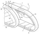
図2〜図8から明らかなとおり、第1手摺2および第2手摺8は、第1握り部4の下流端5が第2握り部10の上流端11と実質的に並行するよう、重複するように配設されて、第1握り部と第2握り部との間には間隙14が残る。図2に示すように、案内部材15が第1手摺2に取り付けられていて、乗客の指が間隙14に入り込むのを防ぐ。第1手摺2は、コンベヤ1に対して第2手摺8よりも内側に位置する。
As apparent from FIGS. 2 to 8, the
図5を参照すると、案内部材15は、重複部分の、手摺ベルトの運転方向から見て進入口側に位置し、第1手摺フレーム6の第1側面7に取り付けられている。手摺ベルトの運転方向から見て、重複部分の下流側には第2案内部材15が設けられ、第2手摺フレーム12の第2側面13に取り付けられている。
Referring to FIG. 5, the
図4、図7、図8から明白なとおり、案内部材15は、第1握り部4近傍で握り部に並行して第1手摺ベルト3真下に伸びる案内端16を含み、それによって指が第1手摺ベルト3の下に入り込むのを防止している(図7を参照)。案内端16には警告部材17が設けられる。この警告部材17は、本例では波形などの形状であり、乗客は第1手摺ベルト3を掴んでいる手の指がそこに触れることで、切替り点に近づいていることに気付く。この切替り点で第1手摺ベルト3から第2手摺ベルト8へ手を移動させなければならない。図7は、第1手摺ベルト3を掴んでいる手が、警告部材17に接触する様子を示す。
As is apparent from FIGS. 4, 7, and 8, the
また、図5、図6、および図7からわかるとおり、案内部材15はさらに、間隙14内で長手方向に垂直に伸びる挿入部材21を含む。この挿入部材は、手摺ベルト3および9上面のTの高さ近くにおいて、間隙の長さ方向および幅方向をある程度埋めて、指が間隙14に入り込むのを防止する。挿入部材21は隣接するベルト間に指が挟まれるのを防ぎ、また、各指を一斉に次の手摺ベルトに載せるように形成されている。たとえベルト間に指を入れようとしても、それは不可能であり、指および手は次の手摺ベルトへと安全に案内される。
Further, as can be seen from FIGS. 5, 6, and 7, the
案内部材15はまた、カバーストリップ20を含む。カバーストリップは、横方向および垂直方向に、第2手摺ベルト3の転換部19の少なくとも一部分にわたって、その曲形状に沿って伸び、乗客の手が第1手摺フレーム6と第2手摺ベルト3の転換部19との間の間隙に巻き込まれるのを防止する。
The
案内部材15は固体材料で形成された一つの部材であり、そこに、案内端16、警告部材17、カバーストリップ20、および挿入部材21が形成されている。
The
再び図1を参照すると、第1手摺2は加速部22に、第2手摺8は加速部22または定速部23に設置され、この場合、第2手摺ベルト9の運転速度は第1手摺ベルト3の運転速度よりも高い。
Referring to FIG. 1 again, the
第1手摺2および第2手摺8はまた、定速部23に設置してもよく、その場合、第1手摺ベルト3と第2手摺ベルト9の運転速度は実質的に同じである。
The
同様に、第1手摺2は定速部23または減速部24に設置し、第2手摺8は減速部24に設置してもよく、その場合、第2手摺ベルト9の運転速度は第1手摺ベルト3の運転速度よりも低い。
Similarly, the
一連の手摺を上述のように重複配設することで、動く歩道の手摺を適度の長さに分割できるため、非常に長い手摺ベルト輪は不要となる。手摺ベルトのループ長は自由に選択できる。 By arranging a series of handrails as described above, the handrails on the moving sidewalk can be divided into appropriate lengths, so that a very long handrail belt ring is not necessary. The loop length of the handrail belt can be freely selected.
本発明は、上述の実施例に限定されるものではなく、本願特許請求の範囲に規定される発明の概念の範囲において、さまざまに変更可能である。したがって、上述の実施例における動く歩道を、動くスロープ、エスカレータ、または同様のコンベヤに置き換えてもよい。 The present invention is not limited to the above-described embodiments, and can be variously modified within the scope of the concept of the invention defined in the claims of the present application. Thus, the moving walkway in the above embodiment may be replaced with a moving slope, escalator, or similar conveyor.
また、当業者にとって明らかなように、本発明は、例として示される上述の実施例に限定されるものではなく、本願特許請求の範囲に規定される発明の概念の範囲において、多様な変形例が実行可能である。 Further, as will be apparent to those skilled in the art, the present invention is not limited to the above-described embodiments shown as examples, and various modifications may be made within the scope of the inventive concept defined in the claims of the present application. Is feasible.
1 コンベヤ
2 第1手摺
3 第1手摺ベルト
4 第1握り部
5 下流端
6 第1手摺フレーム
7 第1側面
8 第2手摺
9 第2手摺ベルト
10 第2握り部
11 上流端
12 第2手摺フレーム
13 第2側面
14 間隙
15 案内部材
16 案内端
17 警告部材
18 戻り部
19 転換部
20 カバーストリップ
21 挿入部材
T 高さ
22 加速部
23 定速部
24 減速部
DESCRIPTION OF SYMBOLS 1
10 Second grip
11 Upstream end
12 Second handrail frame
13 Second side
14 gap
15 Guide member
16 Guide end
17 Warning material
18 Return section
19 Conversion Department
20 Cover strip
21 Insert member T Height
22 Accelerator
23 Constant speed section
24 Reducer
Claims (14)
−第1手摺(2)とを含み、第1手摺は、環状に形成され乗客が手で掴んで支えるための上部第1握り部(4)を有して第1握り部が運送方向に対して下流に位置する下流端(5)を有する動く第1手摺ベルト(3)、該手摺ベルト(3)を支持して案内する第1手摺フレーム(6)、および第1側面(7)を含み、さらに
−運送方向に見て第1手摺の下流に、前記コンベヤに沿って第1手摺(2)と同じ側に設けられ、第1手摺に並行して伸びる第2手摺(8)を含み、第2手摺(8)は、環状に形成され乗客が手で掴んで支えるための上部第2握り部(10)を有して第2握り部が運送方向に対して上流に位置する上流端(11)を有する第2循環手摺ベルト(9)、該手摺ベルト(9)を支持して案内する第2手摺フレーム(12)、および第1手摺フレーム(6)の第1側面(7)に面している第2側面(13)を含む、人を運送する動く歩道、動くスロープ、またはエスカレータにおいて、
第1手摺(2)および第2手摺(8)は、第1握り部(4)の前記下流端(5)が第2握り部(10)の前記上流端(11)と実質的に並行して設けられるよう相互の重複部をもって設置され、第1握り部と第2握り部との間に間隙(14)が残り、第1手摺(2)および/または第2手摺(8)は、乗客の指が前記間隙(14)に入り込むのを防止する案内部材(15)を含むことを特徴とする動く歩道、動くスロープ、またはエスカレータ。 -A conveyor (1) for moving passengers in the direction of carriage;
-A first handrail (2), the first handrail is formed in an annular shape and has an upper first grip portion (4) for a passenger to hold and support with the hand, the first grip portion being in the transport direction A first handrail belt (3) having a downstream end (5) located downstream, a first handrail frame (6) for supporting and guiding the handrail belt (3), and a first side surface (7). And further including a second handrail (8) provided on the same side as the first handrail (2) along the conveyor and extending in parallel with the first handrail, downstream of the first handrail as viewed in the transport direction, The second handrail (8) is formed in an annular shape and has an upper second grip portion (10) for a passenger to hold and support by hand, and the second hand grip portion is located upstream with respect to the carrying direction ( 11) a second circulating handrail belt (9) having a second handrail frame (12) for supporting and guiding the handrail belt (9), and a first side surface (7) of the first handrail frame (6). do it That includes a second side surface (13), moving walkways for transportation of people, in moving ramp or escalator,
In the first handrail (2) and the second handrail (8), the downstream end (5) of the first grip portion (4) is substantially parallel to the upstream end (11) of the second grip portion (10). So that the gap (14) remains between the first grip portion and the second grip portion, and the first handrail (2) and / or the second handrail (8) A moving sidewalk, a moving slope, or an escalator, characterized by including a guide member (15) for preventing a finger of the user from entering the gap (14).
Applications Claiming Priority (2)
| Application Number | Priority Date | Filing Date | Title |
|---|---|---|---|
| FI20050047A FI20050047A (en) | 2005-01-14 | 2005-01-14 | A walkway, ramp or step |
| PCT/FI2006/000014 WO2006075047A1 (en) | 2005-01-14 | 2006-01-11 | Travelator, moving ramp or escalator |
Publications (2)
| Publication Number | Publication Date |
|---|---|
| JP2008526654A true JP2008526654A (en) | 2008-07-24 |
| JP2008526654A5 JP2008526654A5 (en) | 2008-09-18 |
Family
ID=34112599
Family Applications (1)
| Application Number | Title | Priority Date | Filing Date |
|---|---|---|---|
| JP2007550804A Abandoned JP2008526654A (en) | 2005-01-14 | 2006-01-11 | Moving walkway, moving slope, or escalator |
Country Status (6)
| Country | Link |
|---|---|
| US (1) | US7413068B2 (en) |
| EP (1) | EP1836120A1 (en) |
| JP (1) | JP2008526654A (en) |
| CN (1) | CN101102957A (en) |
| FI (1) | FI20050047A (en) |
| WO (1) | WO2006075047A1 (en) |
Families Citing this family (2)
| Publication number | Priority date | Publication date | Assignee | Title |
|---|---|---|---|---|
| EP3309108B1 (en) | 2016-10-14 | 2020-03-25 | Otis Elevator Company | People conveyor and method of operating a people conveyor |
| EP3470360A1 (en) * | 2017-10-10 | 2019-04-17 | Thyssenkrupp Elevator Innovation Center, S.A. | Split handrail for passenger moving walking systems |
Family Cites Families (9)
| Publication number | Priority date | Publication date | Assignee | Title |
|---|---|---|---|---|
| US2578566A (en) * | 1949-01-31 | 1951-12-11 | Multiscope Inc | Escalator handrail |
| DE68919011T2 (en) * | 1988-07-25 | 1995-02-23 | Loderway Pty Ltd | A moving walkway. |
| BR9205899A (en) * | 1991-04-18 | 1994-07-26 | Loderway Pty Ltd | Walkway |
| US5156252A (en) * | 1992-02-18 | 1992-10-20 | Otis Elevator Company | Handrail guard housing shield |
| CA2237028C (en) * | 1997-06-13 | 2002-11-12 | Jean-Marc Caron | Device for deterring unsafe usage of a handrail |
| JP2000318961A (en) * | 1999-05-12 | 2000-11-21 | Ishikawajima Harima Heavy Ind Co Ltd | Handrail for acceleration/deceleration type moving sidewalk |
| JP2001106463A (en) * | 1999-10-07 | 2001-04-17 | Nkk Corp | Handrail device of passenger conveyor |
| JP2004203560A (en) * | 2002-12-25 | 2004-07-22 | Mitsubishi Electric Corp | Moving handrail device of middle part, high speed passenger conveyor |
| FI117173B (en) * | 2003-11-28 | 2006-07-14 | Kone Corp | travolator |
-
2005
- 2005-01-14 FI FI20050047A patent/FI20050047A/en unknown
-
2006
- 2006-01-11 EP EP06701057A patent/EP1836120A1/en not_active Withdrawn
- 2006-01-11 JP JP2007550804A patent/JP2008526654A/en not_active Abandoned
- 2006-01-11 WO PCT/FI2006/000014 patent/WO2006075047A1/en active Application Filing
- 2006-01-11 CN CNA2006800024137A patent/CN101102957A/en active Pending
-
2007
- 2007-07-13 US US11/826,391 patent/US7413068B2/en not_active Expired - Fee Related
Also Published As
| Publication number | Publication date |
|---|---|
| FI20050047A0 (en) | 2005-01-14 |
| EP1836120A1 (en) | 2007-09-26 |
| US7413068B2 (en) | 2008-08-19 |
| US20080011580A1 (en) | 2008-01-17 |
| WO2006075047A1 (en) | 2006-07-20 |
| CN101102957A (en) | 2008-01-09 |
| FI20050047A (en) | 2006-07-15 |
Similar Documents
| Publication | Publication Date | Title |
|---|---|---|
| EP1681260B1 (en) | Escalator with step flange | |
| US7614490B2 (en) | Passenger conveyor handrail having a gripping surface with a generally circular cross-section | |
| JP2008526654A (en) | Moving walkway, moving slope, or escalator | |
| JP2008504192A (en) | Moving walkway system | |
| JP2008526654A5 (en) | ||
| JP2006225148A (en) | Device for warning step of intermediate part high-speed passenger conveyor | |
| US20220289525A1 (en) | Passenger conveyor system | |
| JPH09202581A (en) | Inclination type passenger conveyor | |
| JP2000318961A (en) | Handrail for acceleration/deceleration type moving sidewalk | |
| JP2001106463A (en) | Handrail device of passenger conveyor | |
| JP2845747B2 (en) | Moving sidewalk | |
| JP2003321185A (en) | Moving hand rail of speed variable type passenger conveyor | |
| JP4407227B2 (en) | Variable speed moving walkway | |
| JPH10114486A (en) | Handrail of human transferring device | |
| JPH10265158A (en) | Passenger conveyer device | |
| JPH02225288A (en) | Boarding hall of passenger conveyor | |
| JP2001048457A (en) | Handrail device for variable speed passenger conveyer | |
| JP3011686U (en) | Variable speed moving walkway | |
| JP3456325B2 (en) | Moving handrail on a moving sidewalk | |
| JP2776902B2 (en) | Belt sidewalk equipment | |
| JP2001192193A (en) | High speed escalator | |
| JPH0640689A (en) | Moving handrail of variable speed type passenger conveyor | |
| JPH07101662A (en) | Handrail for acceleration-deceleration type moving footpath | |
| JPH0565977U (en) | Passenger conveyor intermediate entrance / exit | |
| JPH11301956A (en) | Handrail device for passenger conveyor |
Legal Events
| Date | Code | Title | Description |
|---|---|---|---|
| A521 | Request for written amendment filed |
Free format text: JAPANESE INTERMEDIATE CODE: A523 Effective date: 20080801 |
|
| A621 | Written request for application examination |
Free format text: JAPANESE INTERMEDIATE CODE: A621 Effective date: 20080801 |
|
| A762 | Written abandonment of application |
Free format text: JAPANESE INTERMEDIATE CODE: A762 Effective date: 20091127 |