JP2008521520A - Improved sterilization filter device, sterilization device, and sterilization method - Google Patents
Improved sterilization filter device, sterilization device, and sterilization method Download PDFInfo
- Publication number
- JP2008521520A JP2008521520A JP2007543652A JP2007543652A JP2008521520A JP 2008521520 A JP2008521520 A JP 2008521520A JP 2007543652 A JP2007543652 A JP 2007543652A JP 2007543652 A JP2007543652 A JP 2007543652A JP 2008521520 A JP2008521520 A JP 2008521520A
- Authority
- JP
- Japan
- Prior art keywords
- filter
- air
- bacteria
- housing
- air flow
- Prior art date
- Legal status (The legal status is an assumption and is not a legal conclusion. Google has not performed a legal analysis and makes no representation as to the accuracy of the status listed.)
- Pending
Links
Images


Classifications
-
- A—HUMAN NECESSITIES
- A47—FURNITURE; DOMESTIC ARTICLES OR APPLIANCES; COFFEE MILLS; SPICE MILLS; SUCTION CLEANERS IN GENERAL
- A47L—DOMESTIC WASHING OR CLEANING; SUCTION CLEANERS IN GENERAL
- A47L9/00—Details or accessories of suction cleaners, e.g. mechanical means for controlling the suction or for effecting pulsating action; Storing devices specially adapted to suction cleaners or parts thereof; Carrying-vehicles specially adapted for suction cleaners
- A47L9/10—Filters; Dust separators; Dust removal; Automatic exchange of filters
- A47L9/12—Dry filters
- A47L9/122—Dry filters flat
-
- A—HUMAN NECESSITIES
- A45—HAND OR TRAVELLING ARTICLES
- A45D—HAIRDRESSING OR SHAVING EQUIPMENT; EQUIPMENT FOR COSMETICS OR COSMETIC TREATMENTS, e.g. FOR MANICURING OR PEDICURING
- A45D20/00—Hair drying devices; Accessories therefor
- A45D20/04—Hot-air producers
- A45D20/08—Hot-air producers heated electrically
- A45D20/10—Hand-held drying devices, e.g. air douches
- A45D20/12—Details thereof or accessories therefor, e.g. nozzles, stands
-
- A—HUMAN NECESSITIES
- A47—FURNITURE; DOMESTIC ARTICLES OR APPLIANCES; COFFEE MILLS; SPICE MILLS; SUCTION CLEANERS IN GENERAL
- A47K—SANITARY EQUIPMENT NOT OTHERWISE PROVIDED FOR; TOILET ACCESSORIES
- A47K10/00—Body-drying implements; Toilet paper; Holders therefor
- A47K10/48—Drying by means of hot air
-
- A—HUMAN NECESSITIES
- A47—FURNITURE; DOMESTIC ARTICLES OR APPLIANCES; COFFEE MILLS; SPICE MILLS; SUCTION CLEANERS IN GENERAL
- A47L—DOMESTIC WASHING OR CLEANING; SUCTION CLEANERS IN GENERAL
- A47L7/00—Suction cleaners adapted for additional purposes; Tables with suction openings for cleaning purposes; Containers for cleaning articles by suction; Suction cleaners adapted to cleaning of brushes; Suction cleaners adapted to taking-up liquids
- A47L7/04—Suction cleaners adapted for additional purposes; Tables with suction openings for cleaning purposes; Containers for cleaning articles by suction; Suction cleaners adapted to cleaning of brushes; Suction cleaners adapted to taking-up liquids for using the exhaust air for other purposes, e.g. for distribution of chemicals in a room, for sterilisation of the air
-
- A—HUMAN NECESSITIES
- A61—MEDICAL OR VETERINARY SCIENCE; HYGIENE
- A61L—METHODS OR APPARATUS FOR STERILISING MATERIALS OR OBJECTS IN GENERAL; DISINFECTION, STERILISATION OR DEODORISATION OF AIR; CHEMICAL ASPECTS OF BANDAGES, DRESSINGS, ABSORBENT PADS OR SURGICAL ARTICLES; MATERIALS FOR BANDAGES, DRESSINGS, ABSORBENT PADS OR SURGICAL ARTICLES
- A61L9/00—Disinfection, sterilisation or deodorisation of air
- A61L9/015—Disinfection, sterilisation or deodorisation of air using gaseous or vaporous substances, e.g. ozone
- A61L9/04—Disinfection, sterilisation or deodorisation of air using gaseous or vaporous substances, e.g. ozone using substances evaporated in the air without heating
-
- A—HUMAN NECESSITIES
- A61—MEDICAL OR VETERINARY SCIENCE; HYGIENE
- A61L—METHODS OR APPARATUS FOR STERILISING MATERIALS OR OBJECTS IN GENERAL; DISINFECTION, STERILISATION OR DEODORISATION OF AIR; CHEMICAL ASPECTS OF BANDAGES, DRESSINGS, ABSORBENT PADS OR SURGICAL ARTICLES; MATERIALS FOR BANDAGES, DRESSINGS, ABSORBENT PADS OR SURGICAL ARTICLES
- A61L9/00—Disinfection, sterilisation or deodorisation of air
- A61L9/16—Disinfection, sterilisation or deodorisation of air using physical phenomena
-
- B—PERFORMING OPERATIONS; TRANSPORTING
- B01—PHYSICAL OR CHEMICAL PROCESSES OR APPARATUS IN GENERAL
- B01D—SEPARATION
- B01D46/00—Filters or filtering processes specially modified for separating dispersed particles from gases or vapours
- B01D46/0002—Casings; Housings; Frame constructions
- B01D46/0005—Mounting of filtering elements within casings, housings or frames
-
- B—PERFORMING OPERATIONS; TRANSPORTING
- B01—PHYSICAL OR CHEMICAL PROCESSES OR APPARATUS IN GENERAL
- B01D—SEPARATION
- B01D46/00—Filters or filtering processes specially modified for separating dispersed particles from gases or vapours
- B01D46/0027—Filters or filtering processes specially modified for separating dispersed particles from gases or vapours with additional separating or treating functions
- B01D46/0028—Filters or filtering processes specially modified for separating dispersed particles from gases or vapours with additional separating or treating functions provided with antibacterial or antifungal means
-
- B—PERFORMING OPERATIONS; TRANSPORTING
- B01—PHYSICAL OR CHEMICAL PROCESSES OR APPARATUS IN GENERAL
- B01D—SEPARATION
- B01D46/00—Filters or filtering processes specially modified for separating dispersed particles from gases or vapours
- B01D46/10—Particle separators, e.g. dust precipitators, using filter plates, sheets or pads having plane surfaces
-
- D—TEXTILES; PAPER
- D06—TREATMENT OF TEXTILES OR THE LIKE; LAUNDERING; FLEXIBLE MATERIALS NOT OTHERWISE PROVIDED FOR
- D06F—LAUNDERING, DRYING, IRONING, PRESSING OR FOLDING TEXTILE ARTICLES
- D06F58/00—Domestic laundry dryers
- D06F58/20—General details of domestic laundry dryers
-
- B—PERFORMING OPERATIONS; TRANSPORTING
- B01—PHYSICAL OR CHEMICAL PROCESSES OR APPARATUS IN GENERAL
- B01D—SEPARATION
- B01D2257/00—Components to be removed
- B01D2257/91—Bacteria; Microorganisms
-
- B—PERFORMING OPERATIONS; TRANSPORTING
- B01—PHYSICAL OR CHEMICAL PROCESSES OR APPARATUS IN GENERAL
- B01D—SEPARATION
- B01D2267/00—Multiple filter elements specially adapted for separating dispersed particles from gases or vapours
- B01D2267/40—Different types of filters
Abstract
室内空気流に関する装置に用いられる空気伝染細菌フィルタ装置が提供される。空気流は、繊維状フィルタ装置を通過し、この繊維状フィルタ装置の繊維には毒性の高い殺菌性物質が施されており、この殺菌性物質は、空気流中の細菌を捕捉してこれを殺す。木炭注入フィルタが、空気流から毒性物質を除去し、別のフィルタが有益な物質を空気流に放出することができる。フィルタ装置は、微生物が侵入しないよう密封されている。フィルタ装置は、100%の細菌除去を達成する程度まで空気流を滅菌できるようハンドドライヤその他の装置に用いられる。 An airborne bacterial filter device for use in a device relating to indoor airflow is provided. The air flow passes through the fibrous filter device, and the fibers of the fibrous filter device are given a highly toxic bactericidal substance, which traps bacteria in the air flow and removes it. kill. A charcoal injection filter can remove toxic substances from the air stream and another filter can release beneficial substances into the air stream. The filter device is sealed from ingress of microorganisms. Filter devices are used in hand dryers and other devices so that airflow can be sterilized to the extent that 100% bacteria removal is achieved.
Description
本発明は、室内装置で用いられるコンポーネントの改良に関し、室内装置は、室内装置から室内人間活動環境内に放出される内部空気流を有する。 The present invention relates to improvements in components used in indoor devices, where the indoor device has an internal air flow that is discharged from the indoor device into an indoor human activity environment.
本発明の一観点は、特に、かかる室内装置から出る空気流を滅菌するために用いられるフィルタ装置の改良に関する。 One aspect of the present invention relates particularly to improvements in filter devices used to sterilize the air flow exiting such indoor devices.
本発明の他の好ましい観点は、空気流から100%細菌除去を達成する目的に寄与する特徴に関する。 Another preferred aspect of the present invention relates to features that contribute to the goal of achieving 100% bacterial removal from the air stream.
また、本発明の他の観点は、空気流を特にハンドドライヤ、ヘアドライヤ、真空掃除機、換気扇(エアファン)、空気調和機(エアコンディショナ)、冷蔵庫、衣類タンブル乾燥機(これらには限定されない)に放出する改良型装置に関する。 Another aspect of the present invention is that the air flow is not limited to hand dryers, hair dryers, vacuum cleaners, ventilation fans (air fans), air conditioners (air conditioners), refrigerators, and clothing tumble dryers. To the improved device.
空気流装置による細菌のまき散らし
空気を引き込み、次にこの空気を室内人間活動環境内に空気流として放出する室内装置は、病原菌、細菌、及びウイルスをまき散らす又は飛散させる媒介物であることが知られている。その結果、この環境内に居る人たちは、装置から放出された空気によってまき散らされた細菌に容易に接触する場合がある。
Indoor devices that draw air from the airflow device and then release this air as an air flow into the indoor human activity environment are known to be mediators that disperse or scatter pathogens, bacteria, and viruses. ing. As a result, people in this environment may easily come into contact with bacteria scattered by the air released from the device.
例えば、先行技術としては、温風を放出して手を乾燥させる多くの手乾燥装置が挙げられる。かかる手乾燥装置を用いることは、衛生的であると考えられていた。しかしながら、予想に反して、これら先行技術の手乾燥装置は、実際には、病原菌をまき散らす手段であることが判明した。 For example, as a prior art, there are many hand dryers that discharge warm air to dry hands. It has been considered hygienic to use such a hand dryer. Contrary to expectations, however, these prior art hand dryers have actually proved to be a means of spreading pathogenic bacteria.
その理由は、これら先行技術の手乾燥装置からの温風は、それ自体、空気伝染細菌を含んでいるからである。これは、ハンドドライヤがトイレの細菌含有雰囲気から空気を引き込み、温かい病原菌取り込み空気流をユーザの濡れた手に吹き付けるからである。 The reason is that the warm air from these prior art hand dryers itself contains airborne bacteria. This is because the hand dryer draws air from the bacteria-containing atmosphere of the toilet and blows a warm pathogen-intake air stream onto the user's wet hands.
さらに、多くの人は、自分の手を完全に乾燥させるに足るほど長く温風中に自分の手を入れておくことはない。その結果、ユーザの手の温かい水分を含んだ環境は、ハンドドライヤにより手に吹き付けられた細菌が急増するのに理想的である。 In addition, many people do not keep their hands in warm air long enough to completely dry their hands. As a result, the environment containing warm moisture in the user's hand is ideal for the rapid increase of bacteria sprayed on the hand by the hand dryer.
空気流中の微生物の多くは、ハンドドライヤの発熱体によっては殺菌されることはない。さらに、ハンドドライヤからの温風は、細菌が増殖する上で理想的な環境である。その結果、これら生きている細菌は、ユーザの手に吹き付けられる。実のところ、先行技術のかかる温風器は、実際、細菌レベルを最高500%まで増大させる場合のあることが判明した。 Many of the microorganisms in the air stream are not sterilized by the heating element of the hand dryer. Furthermore, the warm air from the hand dryer is an ideal environment for the growth of bacteria. As a result, these living bacteria are sprayed on the user's hand. Indeed, it has been found that such prior art hot air heaters may actually increase the bacterial level up to 500%.
100%には至らない細菌除去の問題
かかる先行技術の手乾燥装置は、公共施設、例えば公共トイレで広く用いられているが、これら装置を或る特定の分野、特に、医療分野、例えば病院や診療所及び更に育児所や食品業界で利用するには抵抗がある。
100% hand dryer problems such prior art bacteria removal does not lead to the public facilities, for example, is widely used in public toilets, a particular field of these devices, in particular, the medical field, for example, a hospital Ya There is resistance to use in clinics and even in childcare and food industries.
例えば、外科医は、手術を行なう前に、抗菌性の液体又は石鹸で自分の手を洗う場合、外科医の手が細菌で再感染されると、又、外科医が先行技術の手乾燥装置の温風中で自分の濡れた手を乾かそうとしても、無益である。 For example, a surgeon may wash his hands with an antibacterial liquid or soap prior to performing surgery, if the surgeon's hand is reinfected with bacteria, and the surgeon may also be using warm air from prior art hand dryers. It is useless to try to dry your wet hands.
また、新たなミレニアムにおいて、ウイルス学者及び公共衛生係員は、致命的な流行性感冒及び他のウイルスの将来における世界的流行をかかる流行が起こるかどうかではなく、いつ起こるかという観点で予測している。かかる全世界的流行が勃発するとすれば、空気流を放出する室内装置に100%の細菌除去が要望されることも又予測できる。もしそうでなければ、かかる装置は、特に公共の場所において、たとえ例えば細菌の内90%を除去できるとしても、依然として世界的流行病において致命的なウイルスをまき散らす媒介物となる。換言すると、流行中、100%の細菌除去は、極めて重要になる。 Also, in the new millennium, virologists and public health officials predict fatal epidemics and the future global outbreaks of other viruses in terms of when such epidemics occur, not when they occur. Yes. If such a global epidemic breaks out, it can also be predicted that 100% bacteria removal is required for indoor devices that emit airflow. If not, such devices remain a vehicle for spreading deadly viruses in pandemics, especially in public places, even if, for example, 90% of bacteria can be removed. In other words, 100% bacteria removal becomes extremely important during the epidemic.
先行技術として挙げられる空気流装置は、細菌を殺すと共に(或いは)装置の空気流から細菌を除去するようになっているが、実際には、かかる公知の製品は、特に長期間にわたる使用により、装置の空気流から細菌の100%の除去に近づいてはいない。 Although the air flow devices listed as prior art are adapted to kill bacteria and / or remove bacteria from the air flow of the device, in practice such known products are particularly prone to long-term use, No approaching 100% removal of bacteria from the airflow of the device.
たとえかかる先行技術の装置が空気流中の細菌の一部を殺菌し又は除去できるとしても、100%細菌除去の最終的な目的は、実現困難なままである。 Even if such prior art devices can sterilize or remove some of the bacteria in the air stream, the ultimate goal of 100% bacteria removal remains difficult to achieve.
それ故、本明細書の説明の始めにあたり、空気流からの細菌の100%の除去という本発明の目的と、細菌の殺菌又は除去を言い張るが、実際の性能においては空気流から細菌を例えば80%、それどころか90%又は95%の除去しか達成できない先行技術の装置とは区別される。 Therefore, at the beginning of the description herein, the purpose of the present invention, 100% removal of bacteria from an air stream, and the sterilization or removal of bacteria, are claimed, but in actual performance bacteria are removed from the air stream, for example 80 %, Even 90% or 95% removal can be distinguished from prior art devices.
100%の細菌除去を目的とする本発明は、必ずしも100%の細菌除去を目的としてはおらずこれを達成することもない先行技術の装置によっては解決される見込みのない別の1組の障害に直面している。 The present invention, aimed at 100% bacteria removal, represents another set of obstacles that are not necessarily aimed at 100% bacteria removal and are not likely to be solved by prior art devices. confronting.
先行技術
先行技術において、空気流装置が滅菌された状態の温風を生じさせることができる試みが行なわれた。この分野における主要な開発分野は、空気流中の細菌を殺菌しようとする紫外(UV)線の使用に焦点が当てられた。しかしながら、予測に反して、UV放射線は、空気流中の細菌を殺菌するという性能が貧弱であるということが確認された。
Prior Art In the prior art, attempts have been made to allow the airflow device to produce hot air in a sterilized state. A major area of development in this area has focused on the use of ultraviolet (UV) radiation to sterilize bacteria in the air stream. However, contrary to expectations, it has been confirmed that UV radiation has poor ability to sterilize bacteria in the air stream.
まず最初に、思い出されなければならないこととして、たとえUV放射線が細菌の大部分を殺菌したとしても、事実としては、空気流中の残りの細菌がユーザの手に依然として到達することができ、そして、分の問題で増加し始める。 First of all, it must be remembered that even if UV radiation sterilizes most of the bacteria, in fact, the remaining bacteria in the air stream can still reach the user's hand, and , Begin to increase in minutes matter.
第2に、微生物学者の中には、UVは単に細菌が繁殖し又は増殖するのを止めるという意味においてUV放射線は実際には細菌を殺すことはなく、単に細菌を減らしているだけであるという考えを持つ人がいる。これが本当ならば、その意味するところは、UV利用ハンドドライヤから出る温風は、依然として、非衛生的な含有物としての生きている細菌を含んでいる。 Second, some microbiologists say that UV radiation does not actually kill bacteria in the sense that UV simply stops the bacteria from growing or multiplying, it just reduces bacteria. Someone has an idea. If this is true, what it means is that the warm air coming out of the UV-based hand dryer still contains live bacteria as an unsanitary content.
この究極的な衛生化レベル、即ち、100%細菌除去は、外科的又は内科的用途にとって特に重要である。この点に関し、本発明者の行なった実験室試験の示すところによれば、現在市場に出ている紫外線利用手乾燥機械の中で、放出された空気流中の細菌を100%殺すものは存在しない。 This ultimate sanitization level, i.e. 100% bacteria removal, is particularly important for surgical or medical applications. In this regard, according to laboratory tests conducted by the inventor, there are ultraviolet hand-dried machines currently on the market that kill 100% of the bacteria in the released air stream. do not do.
かくして、先行技術の手乾燥装置は、手の最も厳しい衛生化基準が特に外科手術の分野や開いた創の医学的治療において極めて重要である医療用途で用いるには都合の良くない場合が多い。 Thus, prior art hand dryers are often not convenient for use in medical applications where the most stringent sanitization standards for hands are critical, especially in the field of surgery and medical treatment of open wounds.
もう1つの問題は、数週間、数か月又はそれどころか数年間にわたり、病原菌が装置の内部に集まる場合があるということである。空気流は、装置内部に引き込まれるので、連続使用により、或る量の細菌が、常時機械内に引き込まれる。換言すると、空気流に接触する機械の内面は全て、常時細菌に曝される。時間の経過につれて、機械の内部は、細菌源になる場合がある。機械をオフにすると又は機械が空気流を発生していない場合、内部の細菌は、成長して増殖し続ける場合がある。先行技術の装置は100%の細菌除去を行なうことができない場合、残った細菌は、装置内に留まり、装置の内面は、経時的に、細菌源になる場合がある。 Another problem is that pathogens may collect inside the device for weeks, months or even years. Since the air flow is drawn inside the device, with continuous use, a certain amount of bacteria is always drawn into the machine. In other words, all inner surfaces of the machine that come into contact with the air stream are constantly exposed to bacteria. Over time, the interior of the machine can become a source of bacteria. If the machine is turned off or the machine is not generating airflow, the bacteria inside may continue to grow and multiply. If the prior art device is unable to perform 100% bacteria removal, the remaining bacteria will remain in the device and the inner surface of the device may become a source of bacteria over time.
他形式の装置を用いても、これらの放出された空気流により細菌が室内にまき散らされる。例えば、空気調和機は、室外か室内環境からかのいずれかから空気を引き込み、次に、空気流を室内に放出する。かくして、空気調和機から放出された空気流中の細菌の100%の殺菌又は除去が行なわれなかった場合、或る期間にわたり、室内環境の空気中の細菌の漸次正味の増加が生じる可能性が多分にある。 Even with other types of devices, these released air streams will disperse bacteria into the room. For example, an air conditioner draws air from either the outdoor or indoor environment and then releases an air flow into the room. Thus, if 100% sterilization or removal of bacteria in the air stream emitted from the air conditioner has not been performed, there may be a gradual net increase of bacteria in the air in the room environment over a period of time. Maybe there.
別な例として、真空掃除機は、これが床又は表面から粒子を吸い上げる際に細菌を引き込む。真空クリーナシステムの濾過は、空気流から粒子を濾過して除去できるが、微粒子としての細菌は空気流中に残存する。これらは、真空クリーナから出る空気流によって室内環境内にまき散らされる。 As another example, a vacuum cleaner draws bacteria as it sucks up particles from the floor or surface. Filtration in a vacuum cleaner system can filter out particles from the air stream, but bacteria as particulates remain in the air stream. These are scattered into the room environment by the air flow exiting the vacuum cleaner.
細菌をまき散らす同一の現象は、空気流を引き込んで放出する他の空気流装置で見られる。これらとしては、例えば、ヘアドライヤ、ファン、及び衣類乾燥機が挙げられる。衣類乾燥機の場合、細菌を含んだ空気が室内環境から引き込まれ、衣類に吹き付けられる。 The same phenomenon of sprinkling bacteria is seen in other airflow devices that draw and release airflow. These include, for example, hair dryers, fans, and clothes dryers. In the case of a clothes dryer, air containing bacteria is drawn from the indoor environment and blown onto the clothes.
冷蔵庫の場合でも、冷蔵庫は、空気を引き込み、細菌を含んだ空気を冷蔵庫の冷蔵室内に放出し、食料を細菌に曝す。 Even in the case of a refrigerator, the refrigerator draws air, releases air containing bacteria into the refrigerator's refrigerated chamber, and exposes food to bacteria.
本発明の幾つかの観点の中の幾つかの目的は、空気流を人間活動環境内に放出する装置が濾過装置を出る空気流中において100%の細菌除去を達成できるようにする1つ又は2つ以上の特徴を個々に又は組み合わせ状態で提供することにある。 Some objectives in some aspects of the invention are one or more that allow a device that releases an air stream into the human activity environment to achieve 100% bacteria removal in the air stream exiting the filtering device. To provide two or more features individually or in combination.
本発明のもう1つの目的は、先行技術における1つ又は2つ以上の問題を解決し又は軽減し、或いは、先行技術に勝る改良型代替手段を提供することにある。 Another object of the present invention is to solve or reduce one or more problems in the prior art, or to provide an improved alternative over the prior art.
本明細書における先行技術に関する説明は、当業者の共通の一般知識の状態に関する承認又は注釈として取られるべきではない。 The prior art description herein should not be taken as an acknowledgment or commentary on the state of common general knowledge of those skilled in the art.
本明細書は、本発明の幾つかの観点を含んでいる。 This specification includes several aspects of the present invention.
本発明の第1の特徴によれば、手を乾燥させる実質的に滅菌された状態の加熱空気の流れを生じさせるようになった滅菌型手乾燥装置であって、
ハウジングと、
前記ハウジング内に設けられていて、手を乾燥させるために使用できる空気を加熱する加熱手段と、
使用の際に空気を前記ハウジングに導入させて前記加熱手段に達するよう移動させる入口手段と、
使用の際に前記加熱手段により加熱された後に空気を手を乾燥させるために使用できる加熱空気として放出させる出口手段と、
空気を空気流として前記入口手段から前記加熱手段を介して前記出口手段に迅速に移動させるようになった空気流発生手段とを有し、
前記装置は、使用の際に空気流を通す細菌捕捉フィルタ手段を備え、前記細菌捕捉フィルタ手段は、使用の際に、空気流中の細菌の大部分を捕捉して保持するようになっており、前記細菌捕捉フィルタ手段から出る空気流は前記細菌捕捉フィルタ手段に入ったときよりも滅菌度が高いものであるようになっており、
前記細菌捕捉フィルタ手段は、繊維状マトリックスの形態をしており、前記繊維状マトリックスは、その繊維に施された毒性の殺菌性物質を有し、前記殺菌性物質は、前記繊維に施された前記殺菌性物質に当たった細菌を殺すことができることを特徴とする装置が提供される。
According to a first aspect of the present invention, there is provided a sterilization type hand drying apparatus adapted to generate a flow of heated air in a substantially sterilized state for drying a hand,
A housing;
Heating means provided in the housing for heating air that can be used to dry the hands;
Inlet means for introducing air into the housing and moving it to reach the heating means in use;
Outlet means for releasing air as heated air that can be used to dry hands after being heated by the heating means in use;
Air flow generating means adapted to quickly move air from the inlet means to the outlet means through the heating means as an air flow;
The apparatus comprises bacteria trapping filter means that allows airflow to pass during use, and the bacteria trapping filter means captures and retains most of the bacteria in the airflow during use. The air flow coming out of the bacteria trapping filter means is more sterilized than when entering the bacteria trapping filter means,
The bacteria trapping filter means is in the form of a fibrous matrix, the fibrous matrix having a toxic bactericidal substance applied to the fiber, and the bactericidal substance applied to the fiber. An apparatus is provided that is capable of killing bacteria that hit the bactericidal substance.
好ましくは、前記殺菌性物質は、液体塗布物質であり、前記液体塗布物質は、前記繊維に施されると、前記繊維上に見受けられる前記殺菌性物質に当たった細菌を捕捉する粘着性被膜を前記繊維上に提供する。 Preferably, the bactericidal substance is a liquid coating substance, and when the liquid coating substance is applied to the fiber, it has an adhesive coating that traps bacteria that hit the bactericidal substance found on the fiber. Provide on the fiber.
例示の実施形態では、前記細菌捕捉フィルタ手段から出た前記空気流は、前記細菌捕捉フィルタ手段に入った前記空気流よりも細菌の数が少ない。 In an exemplary embodiment, the air stream exiting the bacteria capture filter means has fewer bacteria than the air stream entering the bacteria capture filter means.
好ましくは、前記細菌捕捉フィルタ手段から出た前記空気流には、細菌が全く存在せず又は少なくとも実質的に存在しない。 Preferably, there is no or at least substantially no bacteria in the air stream exiting the bacteria capture filter means.
好ましくは、前記細菌捕捉フィルタ手段から出た前記空気流には、粒子状細菌が100%存在しない。 Preferably, 100% of particulate bacteria are not present in the air stream exiting the bacteria capture filter means.
好ましくは、前記細菌捕捉フィルタ手段は、前記空気流が前記加熱手段に到達する前に前記空気流を遮断する。 Preferably, the bacteria trapping filter means blocks the air flow before the air flow reaches the heating means.
好ましくは、前記入口手段は、少なくとも1つの主入口を有し、前記手乾燥装置から放出された空気流は全て、まず最初に前記主入口を通過しなければならないようになっている。 Preferably, the inlet means has at least one main inlet, so that all air flow discharged from the hand dryer must first pass through the main inlet.
好ましくは、前記少なくとも1つの主入口は、全体が前記ハウジング内に設けられている。 Preferably, the at least one main inlet is entirely provided in the housing.
好ましくは、前記少なくとも1つの主入口は、前記空気流発生手段に入った空気が全て前記少なくとも1つの主入口を通過するよう前記空気流発生手段への入口内に設けられている。 Preferably, the at least one main inlet is provided in the inlet to the air flow generating means so that all the air that has entered the air flow generating means passes through the at least one main inlet.
好ましくは、前記空気流発生手段は、ケーシング内に収納され、前記少なくとも1つの主入口は、前記ケーシングに設けられている。 Preferably, the air flow generating means is housed in a casing, and the at least one main inlet is provided in the casing.
変形例として、前記少なくとも1つの主入口は、前記装置の前記ハウジングに設けられ、前記少なくとも1つの主入口は別として、前記ハウジングへの他の全ての入口は、稼働中、空気が前記少なくとも1つの主入口を通ってしか前記ハウジングに入ることができないように密封されている。 As a variant, the at least one main inlet is provided in the housing of the device, and apart from the at least one main inlet, all other inlets to the housing are in operation and air is in the at least one It is sealed so that it can only enter the housing through one main inlet.
好ましくは、前記入口手段は、前記主入口と直列に配置されていて、前記空気流を連続して次々に通す1つ又は2つ以上の補助入口を含む。 Preferably, the inlet means comprises one or more auxiliary inlets arranged in series with the main inlet and through which the air flow passes one after the other.
前記主入口は、単位時間当たりの空気量に関する前記空気流発生手段の空気取り入れ要件を満足するのに十分な空気を収容する相当な空間だけ前記直列配置体中のその次の最も近くに位置する入口から離されているのが良い。 The main inlet is located next to the next in the series arrangement by a substantial space containing enough air to satisfy the air intake requirements of the air flow generating means with respect to the amount of air per unit time It should be separated from the entrance.
前記補助入口のうちの少なくとも1つは、前記ハウジングの外面に設けられていて、前記ハウジングの外部からユーザにより接近可能であるのが良い。 At least one of the auxiliary inlets may be provided on an outer surface of the housing and accessible by a user from the outside of the housing.
好ましくは、前記補助入口は各々、前記細菌捕捉フィルタ手段を備える。 Preferably, each said auxiliary inlet comprises said bacteria capture filter means.
好ましくは、前記主入口は、前記細菌捕捉フィルタ手段を備える。 Preferably, the main inlet comprises the bacteria capture filter means.
好ましくは、前記細菌捕捉フィルタ手段は、前記空気流中の細菌粒子の大部分を遮って捕捉するほど十分高い密度の繊維状高密度フィルタ材料を含む。 Preferably, the bacteria capture filter means comprises a fibrous high density filter material having a sufficiently high density to block and capture most of the bacterial particles in the air stream.
好ましくは、前記フィルタ材料は、不織繊維である。 Preferably, the filter material is a non-woven fiber.
好ましくは、前記フィルタ材料は、前記繊維相互間に約150ミクロンであるよう選択された平均隙間又は細孔を有する。 Preferably, the filter material has an average gap or pore selected to be about 150 microns between the fibers.
好ましくは、前記フィルタ材料の通気度は、約234.7cm3/cm2/秒である。 Preferably, the air permeability of the filter material is about 234.7 cm 3 / cm 2 / sec.
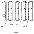
前記細菌捕捉フィルタ手段は、使用中に前記フィルタ材料を交換用フィルタ材料と自動的に交換できるフィルタ交換機構体を含むのが良い。 The bacteria trapping filter means may include a filter replacement mechanism that can automatically replace the filter material with a replacement filter material during use.
好ましくは、前記フィルタ交換機構体は、使用中、前記フィルタ材料を或る期間後、定期的に交換用フィルタ材料と交換する。好ましくは、前記フィルタ交換機構体は、使用中、前記フィルタ材料を連続的に又は間欠的に徐々に交換用フィルタ材料と交換する。好ましくは、前記フィルタ材料は、シート状ストリップの形態をしている。好ましくは、前記フィルタ材料は、電動式リール機構体によって運搬される。 Preferably, the filter replacement mechanism periodically replaces the filter material with a replacement filter material after a period of time during use. Preferably, the filter replacement mechanism gradually replaces the filter material with a replacement filter material continuously or intermittently during use. Preferably, the filter material is in the form of a sheet-like strip. Preferably, the filter material is carried by an electric reel mechanism.
好ましくは、前記装置は、電力を前記装置に供給する電気制御回路を備え、前記電気制御回路は、前記ハウジングを開いたときにユーザが感電死する恐れを最小限に抑えるために前記ハウジングを開いたときに電力の供給を不能にするカットオフ機構体を備える。 Preferably, the device comprises an electrical control circuit for supplying power to the device, the electrical control circuit opening the housing to minimize the risk of user electrocution when opening the housing. A cut-off mechanism that disables the supply of power when the
好ましくは、前記カットオフ機構体は、第1の状態にあるときにのみ、電力供給を可能にする二状態スイッチを有し、前記ハウジングを閉じたときに、前記スイッチを第1の状態に維持するアクチュエータが、前記ハウジング内に設けられ、前記アクチュエータは、前記ハウジングを開いたときに前記スイッチを第2の状態に作動させ、それにより、前記ハウジングが開かれたときに、前記装置への電力供給を不能にする。 Preferably, the cut-off mechanism has a two-state switch that enables power supply only when in the first state, and maintains the switch in the first state when the housing is closed. An actuator is provided in the housing that activates the switch to a second state when the housing is opened, thereby providing power to the device when the housing is opened. Disable supply.
好ましくは、前記カットオフ機構体は、押し下げられたときにのみ、電力供給を可能にする弾性取り付けスイッチを有し、カットオフ機構体のアクチベータが、前記ハウジング内に設けられ、前記カットオフ機構体アクチベータは、前記ハウジングを閉じたときに、前記スイッチを押し下げ、前記ハウジングを開いたときに前記スイッチを持ち上げてオフにし、それにより、前記ハウジングを開いたときに、前記装置への電力供給を不能にするよう構成されている。 Preferably, the cut-off mechanism has an elastic mounting switch that enables power supply only when pressed down, and an activator of the cut-off mechanism is provided in the housing, and the cut-off mechanism The activator depresses the switch when the housing is closed, and lifts the switch off when the housing is opened, thereby disabling power supply to the device when the housing is opened. It is configured to be
好ましくは、前記弾性取り付けスイッチは、前記ハウジングのフードが着脱自在に取り付け可能なベースマウントに取り付けられ、前記カットオフ機構体アクチベータは、前記フードの内面に取り付けられている。 Preferably, the elastic attachment switch is attached to a base mount to which the hood of the housing can be detachably attached, and the cut-off mechanism activator is attached to the inner surface of the hood.
好ましくは、前記カットオフ機構体アクチベータは、前記ハウジングのフードが着脱自在に取り付け可能なベースマウントに取り付けられ、前記弾性取り付けスイッチは、前記フードの内面に取り付けられている。 Preferably, the cut-off mechanism activator is attached to a base mount to which the hood of the housing can be detachably attached, and the elastic attachment switch is attached to the inner surface of the hood.
前記カットオフ機構体アクチベータは、前記カットオフ機構体と接触状態にあるときに前記カットオフ機構体を作動させるデプレッサ(depressor )の形態をしているのが良い。 The cut-off mechanism activator may be in the form of a depressor that activates the cut-off mechanism when in contact with the cut-off mechanism.
前記ベースマウントは、直立取り付け面に締結されるようになっており、前記手乾燥装置は、前記ハウジングの前記ベースマウントに取り付けることにより前記直立取り付け面上に設置できるようになっているのが良い。 The base mount may be fastened to an upright mounting surface, and the hand dryer may be installed on the upright mounting surface by attaching to the base mount of the housing. .
前記手乾燥装置は、前記手乾燥装置が前記手乾燥装置の周りの周囲大気の一部を効果的に滅菌するように所定期間にわたり前記空気流発生手段を定期的に自動作動させるタイマ制御回路を備えているのが良い。 The hand dryer includes a timer control circuit that automatically and periodically activates the air flow generating means over a predetermined period so that the hand dryer effectively sterilizes a part of the ambient atmosphere around the hand dryer. It is good to have.
前記タイマ制御回路は、前記加熱手段を同時に作動させることなく、前記装置を自動作動させるのが良い。 The timer control circuit may automatically operate the device without simultaneously operating the heating means.
変形例として、前記タイマ制御回路は、前記発熱体を同時に作動させながら前記装置を自動作動させても良い。 As a modification, the timer control circuit may automatically operate the device while simultaneously operating the heating elements.
前記タイマ制御回路は、光センサ手段を備えるのが良く、前記タイマ制御回路は、前記光センサにより周囲光が存在していることが示された場合にのみ、前記装置を自動作動させるに過ぎない。 The timer control circuit may comprise light sensor means, and the timer control circuit only automatically activates the device when the light sensor indicates that ambient light is present. .
好ましくは、前記装置は、前記出口手段の近くに手があることを検出するハンドセンサ手段を備え、前記装置は、手がそのように検出されたとき、空気流発生手段及び前記加熱手段を作動させるようになっており、前記タイマ制御回路は、前記ハンドセンサ手段により前記出口手段の付近に手が存在していないことが検出された場合にのみ前記装置を自動作動させる。 Preferably, the apparatus comprises hand sensor means for detecting the presence of a hand in the vicinity of the outlet means, and the apparatus activates the air flow generating means and the heating means when a hand is so detected. The timer control circuit automatically activates the device only when the hand sensor means detects that no hand is present near the outlet means.
好ましくは、前記細菌捕捉フィルタ手段は、以下に説明する空気伝染細菌フィルタ装置を含む。 Preferably, the bacteria trapping filter means includes an airborne bacteria filter device described below.
本発明の第2の特徴によれば、手を乾燥させるための滅菌型手乾燥装置から実質的に滅菌状態の加熱空気の流れを生じさせる方法であって、
空気流発生手段を用いて空気を空気流として迅速に動かすステップと、
前記空気を加熱手段により加熱して前記空気流が手を乾燥させるために使用できるようにするステップと、
使用の際に前記空気流を通過させる細菌捕捉フィルタ手段を備えた前記手乾燥装置を用意するステップとを有し、
前記細菌捕捉フィルタ手段は、使用の際に、空気流中の細菌の大部分を捕捉して保持するようになっており、前記細菌捕捉フィルタ手段から出る空気流は前記細菌捕捉フィルタ手段に入ったときよりも滅菌度が高いものであるようになっており、
前記細菌捕捉フィルタ手段は、繊維状マトリックスの形態をしており、前記繊維状マトリックスは、その繊維に施された毒性の殺菌性物質を有し、前記殺菌性物質は、前記繊維に施された前記殺菌性物質に当たった細菌を殺すことができることを特徴とする方法が提供される。
According to a second aspect of the present invention, there is provided a method for producing a substantially sterilized flow of heated air from a sterilizing hand dryer for drying hands,
Using air flow generating means to quickly move air as an air flow;
Heating the air by a heating means so that the air stream can be used to dry hands;
Providing the hand dryer with a bacteria capture filter means that allows the air flow to pass in use;
The bacteria trapping filter means captures and retains most of the bacteria in the air stream during use, and the air stream exiting the bacteria trapping filter means enters the bacteria trapping filter means. It is designed to have a higher degree of sterilization than
The bacteria trapping filter means is in the form of a fibrous matrix, the fibrous matrix having a toxic bactericidal substance applied to the fiber, and the bactericidal substance applied to the fiber. Provided is a method characterized in that it can kill bacteria that hit the bactericidal substance.
本発明の第3の特徴によれば、手を乾燥させる実質的に滅菌された状態の加熱空気の流れを生じさせるようになった滅菌型手乾燥装置であって、
ハウジングと、
前記ハウジング内に設けられていて、手を乾燥させるために使用できる空気を加熱する加熱手段と、
使用の際に空気を前記ハウジングに導入させて前記加熱手段に達するよう移動させる入口手段と、
使用の際に前記加熱手段により加熱された後に空気を手を乾燥させるために使用できる加熱空気として放出させる出口手段と、
空気を空気流として前記入口手段から前記加熱手段を介して前記出口手段に迅速に移動させるようになった空気流発生手段とを有し、
前記装置は、電力を前記装置に供給する電気制御回路を備え、
前記電気制御回路は、前記ハウジングを開いたときにユーザが感電死する恐れを最小限に抑えるために前記ハウジングを開いたときに電力の供給を不能にするカットオフ機構体を備えていることを特徴とする装置が提供される。
According to a third aspect of the present invention, there is provided a sterilizing hand drying device adapted to generate a flow of heated air in a substantially sterilized state for drying the hand,
A housing;
Heating means provided in the housing for heating air that can be used to dry the hands;
Inlet means for introducing air into the housing and moving it to reach the heating means in use;
Outlet means for releasing air as heated air that can be used to dry hands after being heated by the heating means in use;
Air flow generating means adapted to quickly move air from the inlet means to the outlet means through the heating means as an air flow;
The device comprises an electrical control circuit that supplies power to the device;
The electrical control circuit includes a cut-off mechanism that disables power supply when the housing is opened in order to minimize the risk of a user being electrocuted when the housing is opened. An apparatus is provided.
好ましくは、前記カットオフ機構体は、第1の状態にあるときにのみ、電力供給を可能にする二状態スイッチを有し、前記ハウジングを閉じたときに、前記スイッチを第1の状態に維持するアクチュエータが、前記ハウジング内に設けられ、前記アクチュエータは、前記ハウジングを開いたときに前記スイッチを第2の状態に作動させ、それにより、前記ハウジングが開かれたときに、前記装置への電力供給を不能にする。 Preferably, the cut-off mechanism has a two-state switch that enables power supply only when in the first state, and maintains the switch in the first state when the housing is closed. An actuator is provided in the housing that activates the switch to a second state when the housing is opened, thereby providing power to the device when the housing is opened. Disable supply.
好ましくは、前記カットオフ機構体は、押し下げられたときにのみ、電力供給を可能にする弾性取り付けスイッチを有し、カットオフ機構体のアクチベータが、前記ハウジング内に設けられ、前記カットオフ機構体アクチベータは、前記ハウジングを閉じたときに、前記スイッチを押し下げ、前記ハウジングを開いたときに前記スイッチを持ち上げてオフにし、それにより、前記ハウジングを開いたときに、前記装置への電力供給を不能にするよう構成されている。 Preferably, the cut-off mechanism has an elastic mounting switch that enables power supply only when pressed down, and an activator of the cut-off mechanism is provided in the housing, and the cut-off mechanism The activator depresses the switch when the housing is closed, and lifts the switch off when the housing is opened, thereby disabling power supply to the device when the housing is opened. It is configured to be
前記弾性取り付けスイッチは、前記ハウジングのフードが着脱自在に取り付け可能なベースマウントに取り付けられのが良く、前記カットオフ機構体アクチベータは、前記フードの内面に取り付けられている。 The elastic attachment switch may be attached to a base mount to which the hood of the housing can be detachably attached, and the cut-off mechanism activator is attached to the inner surface of the hood.
前記カットオフ機構体アクチベータは、前記ハウジングのフードが着脱自在に取り付け可能なベースマウントに取り付けられるのが良く、前記弾性取り付けスイッチは、前記フードの内面に取り付けられている。 The cut-off mechanism activator may be attached to a base mount to which the hood of the housing can be detachably attached, and the elastic attachment switch is attached to the inner surface of the hood.
前記カットオフ機構体アクチベータは、前記カットオフ機構体と接触状態にあるときに前記カットオフ機構体を作動させるデプレッサ(depressor )の形態をしているのが良い。 The cut-off mechanism activator may be in the form of a depressor that activates the cut-off mechanism when in contact with the cut-off mechanism.
前記ベースマウントは、直立取り付け面に締結されるようになっているのが良く、前記手乾燥装置は、前記ハウジングの前記ベースマウントに取り付けることにより前記直立取り付け面上に設置できるようになっている。 The base mount may be fastened to an upright mounting surface, and the hand dryer can be installed on the upright mounting surface by attaching to the base mount of the housing. .
本発明の第4の特徴によれば、滅菌型手乾燥装置のハウジングのフードが着脱自在に取り付けられるようになったベースプレートであって、
前記手乾燥装置は、電力を前記装置に供給する電気制御回路を備え、
前記ベースプレートは、使用の際に、前記フードが前記ベースプレートに取り付けられた状態で、前記ハウジングが開かれると、前記電気制御回路への電力供給を不能にして前記ハウジングを開いたときにユーザが感電死する恐れを最小限に抑えるためのカットオフ機構体を備えていることを特徴とするベースプレートが提供される。
According to a fourth aspect of the present invention, there is provided a base plate to which a hood of a housing of a sterilization type hand dryer is detachably attached,
The hand dryer includes an electrical control circuit that supplies power to the device;
When the base plate is used, when the housing is opened with the hood attached to the base plate, electric power is not supplied to the electric control circuit and the user is exposed to electric shock when the housing is opened. A base plate is provided that includes a cut-off mechanism for minimizing the risk of death.
本発明の第5の特徴によれば、手を乾燥させる実質的に滅菌された状態の加熱空気の流れを生じさせるようになった滅菌型手乾燥装置であって、
ハウジングと、
前記ハウジング内に設けられていて、手を乾燥させるために使用できる空気を加熱する加熱手段と、
使用の際に空気を前記ハウジングに導入させて前記加熱手段に達するよう移動させる入口手段と、
使用の際に前記加熱手段により加熱された後に空気を手を乾燥させるために使用できる加熱空気として放出させる出口手段と、
空気を空気流として前記入口手段から前記加熱手段を介して前記出口手段に迅速に移動させるようになった空気流発生手段とを有し、
前記手乾燥装置は、前記空気流発生手段を所定の期間にわたり定期的に自動作動させるタイマ制御回路を備えていることを特徴とする装置が提供される。
According to a fifth aspect of the present invention, there is provided a sterilizing hand drying device adapted to generate a flow of heated air in a substantially sterilized state for drying the hand,
A housing;
Heating means provided in the housing for heating air that can be used to dry the hands;
Inlet means for introducing air into the housing and moving it to reach the heating means in use;
Outlet means for releasing air as heated air that can be used to dry hands after being heated by the heating means in use;
Air flow generating means adapted to quickly move air from the inlet means to the outlet means through the heating means as an air flow;
The hand dryer is provided with a timer control circuit that automatically and periodically activates the airflow generating means over a predetermined period.
前記タイマ制御回路は、前記加熱手段を同時に作動させることなく、前記装置を自動作動させるのか良い。 The timer control circuit may automatically operate the device without simultaneously operating the heating means.
変形例として、前記タイマ制御回路は、前記発熱体を同時に作動させながら前記装置を自動作動させても良い。 As a modification, the timer control circuit may automatically operate the device while simultaneously operating the heating elements.
前記タイマ制御回路は、光センサ手段を備えるのが良く、前記タイマ制御回路は、前記光センサにより周囲光が存在していることが示された場合にのみ、前記装置を自動作動させるに過ぎない。 The timer control circuit may comprise light sensor means, and the timer control circuit only automatically activates the device when the light sensor indicates that ambient light is present. .
前記装置は、前記出口手段の近くに手があることを検出するハンドセンサ手段を備えるのが良く、前記装置は、手がそのように検出されたとき、空気流発生手段及び前記加熱手段を作動させるようになっており、前記タイマ制御回路は、前記ハンドセンサ手段により前記出口手段の付近に手が存在していないことが検出された場合にのみ前記装置を自動作動させる。 The apparatus may comprise hand sensor means for detecting the presence of a hand in the vicinity of the outlet means, and the apparatus activates the air flow generating means and the heating means when a hand is so detected. The timer control circuit automatically activates the device only when the hand sensor means detects that no hand is present near the outlet means.
前記装置は、フレグランスの源であるフレグランス材料を備えるのが良く、前記フレグランスが前記空気流中に入り込むようになっている。 The device may comprise a fragrance material that is a source of fragrance, such that the fragrance penetrates into the air stream.
本発明の第6の特徴によれば、所定期間にわたり滅菌型手乾燥装置の空気流発生手段を定期的に自動作動させるようになったタイミング回路コンポーネントであって、
前記滅菌型手乾燥装置は、手を乾燥させるための実質的に滅菌状態の加熱空気の流れを生じさせるようになっており、前記滅菌型手乾燥装置は、
ハウジングと、
前記ハウジング内に設けられていて、手を乾燥させるために使用できる空気を加熱する加熱手段と、
使用の際に空気を前記ハウジングに導入させて前記加熱手段に達するよう移動させる入口手段と、
使用の際に前記加熱手段により加熱された後に空気を手を乾燥させるために使用できる加熱空気として放出させる出口手段とを有し、
前記空気流発生手段は、前記空気を前記入口手段から前記加熱手段を介して前記出口手段まで空気流として迅速に移動させるようになっており、前記タイマ制御回路は、所定期間にわたって前記空気流発生手段を定期的に自動作動させるようになっていることを特徴とするタイミング回路コンポーネントが提供される。
According to a sixth aspect of the present invention, there is provided a timing circuit component adapted to automatically automatically operate the air flow generating means of the sterilized hand dryer over a predetermined period,
The sterilization type hand drying device is adapted to generate a flow of heated air in a substantially sterilized state for drying hands,
A housing;
Heating means provided in the housing for heating air that can be used to dry the hands;
Inlet means for introducing air into the housing and moving it to reach the heating means in use;
Outlet means for releasing air as heated air that can be used to dry hands after being heated by the heating means in use;
The air flow generating means is adapted to quickly move the air from the inlet means to the outlet means through the heating means as the air flow, and the timer control circuit generates the air flow over a predetermined period. A timing circuit component is provided, characterized in that the means are adapted to automatically activate periodically.
本発明の第7の特徴によれば、手を乾燥させるための実質的に滅菌状態の加熱空気の流れを生じさせるようになっている滅菌型手乾燥装置の周りの周囲大気を滅菌する方法であって、
所定期間にわたって前記空気流発生手段を定期的に自動作動させるようになったタイマ制御回路を備える手乾燥装置を用意するステップと、
前記タイマ制御回路を用いて所定期間にわたり定期的に前記滅菌型手乾燥装置を自動作動させるステップとを有し、前記手乾燥装置は、
ハウジングと、
前記ハウジング内に設けられていて、手を乾燥させるために使用できる空気を加熱する加熱手段と、
使用の際に空気を前記ハウジングに導入させて前記加熱手段に達するよう移動させる入口手段と、
使用の際に前記加熱手段により加熱された後に空気を手を乾燥させるために使用できる加熱空気として放出させる出口手段と、
空気を空気流として前記入口手段から前記加熱手段を介して前記出口手段に迅速に移動させるようになった空気流発生手段とを有することを特徴とする方法が提供される。
According to a seventh aspect of the present invention, there is provided a method for sterilizing the ambient atmosphere around a sterilizing hand dryer that is adapted to produce a flow of substantially sterilized heated air for drying hands. There,
Providing a hand dryer with a timer control circuit adapted to automatically automatically actuate the airflow generation means over a predetermined period;
Automatically operating the sterilization type hand drying device periodically over a predetermined period using the timer control circuit, the hand drying device,
A housing;
Heating means provided in the housing for heating air that can be used to dry the hands;
Inlet means for introducing air into the housing and moving it to reach the heating means in use;
Outlet means for releasing air as heated air that can be used to dry hands after being heated by the heating means in use;
And an air flow generating means adapted to rapidly move air as an air flow from the inlet means to the outlet means via the heating means.
本発明の第8の特徴によれば、空気を乾燥させるための加熱空気の空気流を生じさせるようになった手乾燥装置の周りの周囲大気に香りを付ける方法であって、
所定期間にわたり空気流発生手段を定期的に自動作動させるようになったタイマ制御回路を備える前記手乾燥装置を用意するステップと、
前記手乾燥装置がフレグランスの源であるフレグランス材料を備えるようにし、前記フレグランスが前記空気流中に入り込むようにするステップと、
前記タイマ制御回路を用いて所定期間にわたり定期的に前記手乾燥装置を自動作動させ、それにより、空気流中の前記フレグランスが前記手乾燥装置の周りの周囲大気に効果的に香りを付けるようにするステップとを有し、
前記手乾燥装置は、
ハウジングと、
前記ハウジング内に設けられていて、手を乾燥させるために使用できる空気を加熱する加熱手段と、
使用の際に空気を前記ハウジングに導入させて前記加熱手段に達するよう移動させる入口手段と、
使用の際に前記加熱手段により加熱された後に空気を手を乾燥させるために使用できる加熱空気として放出させる出口手段と、
空気を空気流として前記入口手段から前記加熱手段を介して前記出口手段に迅速に移動させるようになった空気流発生手段とを有することを特徴とする周囲大気の香り付け方法が提供される。
According to an eighth aspect of the present invention, there is provided a method for scenting the ambient atmosphere around a hand-drying device adapted to generate an air flow of heated air for drying air,
Providing the hand dryer with a timer control circuit adapted to automatically automatically actuate the air flow generating means over a predetermined period;
Allowing the hand dryer to comprise a fragrance material that is a source of fragrance, allowing the fragrance to enter the air stream;
Using the timer control circuit to automatically activate the hand dryer periodically for a predetermined period of time so that the fragrance in the air stream effectively scents the ambient atmosphere around the hand dryer And a step of
The hand dryer is
A housing;
Heating means provided in the housing for heating air that can be used to dry the hands;
Inlet means for introducing air into the housing and moving it to reach the heating means in use;
Outlet means for releasing air as heated air that can be used to dry hands after being heated by the heating means in use;
There is provided an air atmosphere scenting method comprising air flow generating means adapted to rapidly move air as an air flow from the inlet means to the outlet means via the heating means.
本発明の第9の特徴によれば、手を乾燥させるための実質的に滅菌状態の加熱空気の流れを生じさせるようになった滅菌型手乾燥装置であって、
ハウジングと、
前記ハウジング内に設けられていて、手を乾燥させるために使用できる空気を加熱する加熱手段と、
使用の際に空気を前記ハウジングに導入させて前記加熱手段に達するよう移動させる入口手段と、
使用の際に前記加熱手段により加熱された後に空気を手を乾燥させるために使用できる加熱空気として放出させる出口手段と、
空気を空気流として前記入口手段から前記加熱手段を介して前記出口手段に迅速に移動させるようになった空気流発生手段と、
前記空気流を濾過するようになったフィルタ材料とを有し、
前記装置は、使用中、前記フィルタ材料を交換用フィルタ材料と自動的に交換することができるフィルタ交換機構体を有することを特徴とする装置が提供される。
According to a ninth aspect of the present invention, there is provided a sterile hand-drying device adapted to generate a flow of substantially sterilized heated air for drying hands,
A housing;
Heating means provided in the housing for heating air that can be used to dry the hands;
Inlet means for introducing air into the housing and moving it to reach the heating means in use;
Outlet means for releasing air as heated air that can be used to dry hands after being heated by the heating means in use;
An air flow generating means adapted to quickly move air as an air flow from the inlet means to the outlet means through the heating means;
A filter material adapted to filter the air stream,
The apparatus is provided with a filter exchange mechanism that can automatically exchange the filter material with a replacement filter material during use.
本発明の第10の特徴によれば、手を乾燥させるための実質的に滅菌状態の加熱空気の流れを生じさせるようになった滅菌型手乾燥装置であって、
ハウジングと、
前記ハウジング内に設けられていて、手を乾燥させるために使用できる空気を加熱する加熱手段と、
使用の際に空気を前記ハウジングに導入させて前記加熱手段に達するよう移動させる入口手段と、
使用の際に前記加熱手段により加熱された後に空気を手を乾燥させるために使用できる加熱空気として放出させる出口手段と、
空気を空気流として前記入口手段から前記加熱手段を介して前記出口手段に迅速に移動させるようになった空気流発生手段とを有し、
前記入口手段は、少なくとも1つの主入口を含み、前記装置内の空気流は全て、前記少なくとも1つの主入口を通過しなければならず、
前記少なくとも1つの主入口は、前記空気流発生手段への入口内に設けられ、前記空気流発生手段に入る空気が全て、この少なくとも1つの主入口を通過して濾過されるようになっていることを特徴とする装置が提供される。
According to a tenth aspect of the present invention, there is provided a sterilization type hand drying device adapted to generate a flow of substantially sterilized heated air for drying a hand,
A housing;
Heating means provided in the housing for heating air that can be used to dry the hands;
Inlet means for introducing air into the housing and moving it to reach the heating means in use;
Outlet means for releasing air as heated air that can be used to dry hands after being heated by the heating means in use;
Air flow generating means adapted to quickly move air from the inlet means to the outlet means through the heating means as an air flow;
The inlet means includes at least one main inlet, and all air flow in the device must pass through the at least one main inlet;
The at least one main inlet is provided in the inlet to the air flow generating means so that all air entering the air flow generating means is filtered through the at least one main inlet. There is provided an apparatus characterized in that.
本発明の第11の特徴によれば、空気流を引き込み、空気流を人間活動環境内に放出する装置に用いられるようになった空気伝染細菌フィルタ装置であって、前記フィルタ装置は、空気流が順番に通る以下のもの、即ち、
i)繊維状マトリックスの形態をした捕捉フィルタ手段を有し、前記繊維状マトリックスは、その繊維に施された毒性の殺菌性物質を有し、前記殺菌性物質は、前記繊維に施された前記殺菌性物質に当たった細菌を殺すことができることを特徴とするフィルタ装置が提供される。
According to an eleventh aspect of the present invention, there is provided an airborne bacterial filter device adapted for use in a device that draws an air flow and releases the air flow into a human activity environment, the filter device comprising: Is the following in order:
i) having capture filter means in the form of a fibrous matrix, the fibrous matrix having a toxic bactericidal substance applied to the fiber, the bactericidal substance being applied to the fiber; A filter device is provided that is capable of killing bacteria that hit a bactericidal substance.
好ましくは、前記捕捉フィルタ手段の通過後に、前記空気流は、
ii)カーボンフィルタ手段を通過し、前記カーボンフィルタ手段は、前記空気流を遮って前記空気流から前記捕捉フィルタ手段に由来する毒性の殺菌性物質のうちの幾分かを除去し、前記フィルタ装置を出て前記人間活動領域内に入る空気流には、細菌と微量の殺菌性物質の両方が実質的に含まれないようにする。
Preferably, after passing through the capture filter means, the air flow is
ii) passes through the carbon filter means, the carbon filter means blocks the air flow and removes some of the toxic bactericidal substances originating from the capture filter means from the air flow, and the filter device The air flow leaving the human activity area should be substantially free of both bacteria and traces of bactericidal substances.
好ましくは、前記空気伝染細菌フィルタ装置は、全体が前記装置の内部に配置されている。 Preferably, the airborne bacterial filter device is entirely disposed inside the device.
好ましくは、前記フィルタ装置は、フィルタバリヤ手段を備え、前記フィルタバリヤ手段は、使用の際に、前記フィルタ装置のための細菌不透性バリヤとなるよう前記捕捉フィルタ手段及び前記木炭フィルタ手段を収容している。 Preferably, said filter device comprises filter barrier means, said filter barrier means containing said capture filter means and said charcoal filter means so that in use they become a bacteria-impermeable barrier for said filter device. is doing.
好ましくは、前記フィルタバリヤ手段の前記細菌不透性バリヤは、前記捕捉フィルタ手段及び前記木炭フィルタ手段を前記装置の内部から分離して、前記空気流に使用された場合、前記装置内部の細菌又は他の汚染要因物が前記捕捉フィルタ手段を介してのみ前記フィルタ装置に入ることができ、前記フィルタ装置の他の部分を介しては前記フィルタ装置に入ることができないようになっている。 Preferably, the bacteria impervious barrier of the filter barrier means separates the capture filter means and the charcoal filter means from the interior of the apparatus and when used in the air flow, Other contaminants can enter the filter device only through the trapping filter means and cannot enter the filter device through other parts of the filter device.
好ましくは、前記細菌不透性バリヤは、互いに嵌まり合うようになったコンポーネントを有し、互いに嵌められると、細菌が前記コンポーネントの当接箇所を通って前記フィルタ装置の内部に入ることができないようになっている。 Preferably, the bacteria-impermeable barrier has components adapted to fit together, and when fitted together, bacteria cannot enter the filter device through the contact points of the components. It is like that.
好ましくは、前記フィルタバリヤ手段の前記細菌不透性バリヤは又、前記フィルタ装置内部の生きている細菌が前記フィルタ装置から逃げ出て前記装置内部に戻るのを阻止する。 Preferably, the bacteria impervious barrier of the filter barrier means also prevents live bacteria inside the filter device from escaping from the filter device and back into the device.
好ましくは、前記捕捉フィルタ手段と前記木炭フィルタ手段は、前記細菌不透性バリヤ内に密封された容積部だけ離されており、前記容積部は、前記空気流が前記捕捉フィルタ手段を出た後に入る一時的行き先として働くようになっている。 Preferably, the capture filter means and the charcoal filter means are separated by a volume sealed within the bacteria-impermeable barrier, the volume being after the air flow exits the capture filter means Work as a temporary destination to enter.
好ましくは、前記捕捉フィルタ手段と前記木炭フィルタ手段は、これらの間の前記容積部が平らであり且つ平面状であるように全体として互いに平行である。 Preferably, the capture filter means and the charcoal filter means are generally parallel to each other so that the volume between them is flat and planar.
好ましくは、使用中、前記空気流は、前記空気流が前記捕捉フィルタ手段及び前記木炭フィルタ手段の各々の表面に実質的に垂直であるような仕方で前記捕捉フィルタ手段から出て前記木炭フィルタ手段に入る。 Preferably, in use, the air flow exits the capture filter means in a manner such that the air flow is substantially perpendicular to the surface of each of the capture filter means and the charcoal filter means. to go into.
好ましくは、前記捕捉フィルタ手段及び前記木炭フィルタ手段の次に連続して、有益な放出可能物質を収容した放出フィルタ手段が設けられ、前記有益な放出可能物質は、使用中、前記フィルタ装置から放出された空気流中に入れ込まれるようになっている。 Preferably, a release filter means containing a beneficial releasable substance is provided in succession next to the capture filter means and the charcoal filter means, the beneficial releasable substance being released from the filter device during use. Into the air stream.
前記捕捉フィルタ手段及び前記木炭フィルタ手段の次に連続して、各々が有益な放出可能物質を収容した2つ又は3つ以上の放出フィルタ手段が設けられるのが良く、前記有益な放出可能物質は、使用中、前記フィルタ装置から放出された空気流中に入れ込まれるようになっている。 Two or more release filter means, each containing a beneficial releasable substance, may be provided next to the capture filter means and the charcoal filter means, the beneficial releasable substance being In use, the air is discharged from the filter device.
前記有益な放出可能物質は、空気によって運ばれる仕方でユーザに投与できる医薬品を含むのが良い。 The beneficial releasable material may include a medicinal product that can be administered to the user in a manner that is carried by air.
前記有益な放出可能物質は、フレグランスを含むのが良い。 The beneficial releasable material may include a fragrance.
前記有益な放出可能物質は、抗菌物質を含むのが良い。 The beneficial releasable material may include an antimicrobial material.
好ましくは、前記有益な放出可能物質は、以下に説明する空気流活性化配合物と組み合わされ、前記有益な放出可能物質は、活性物質である。 Preferably, the beneficial releasable material is combined with an air flow activated formulation as described below, and the beneficial releasable material is an active material.
少なくとも、前記放出フィルタ手段は、平らなフィルタ材料片の形態をしているのが良く、前記平らなフィルタ材料片は、前記平らなフィルタ材料片が前記空気流中ではためくことができるよう前記フィルタ装置内に支持されている。 At least the discharge filter means may be in the form of a flat filter material piece, the flat filter material piece being such that the flat filter material piece can flutter in the air stream. Supported in the device.
好ましくは、前記殺菌性物質は、液体塗布物質であり、前記液体塗布物質は、前記繊維に施されると、前記繊維上に見受けられる前記殺菌性物質に当たった細菌を捕捉する粘着性被膜を前記繊維上に提供する。 Preferably, the bactericidal substance is a liquid coating substance, and when the liquid coating substance is applied to the fiber, it has an adhesive coating that traps bacteria that hit the bactericidal substance found on the fiber. Provide on the fiber.
好ましくは、前記粘着性被膜は、当たった細菌粒子を前記繊維に物理的に保持することができ、前記細菌は、その場所に保持されて殺されるようになる。 Preferably, the adhesive coating can physically hold the struck bacterial particles to the fibers so that the bacteria are held in place and killed.
好ましくは、前記木炭フィルタ手段は、木炭粒子が注入された繊維状マトリックスである。 Preferably, the charcoal filter means is a fibrous matrix infused with charcoal particles.
好ましくは、前記木炭フィルタ手段は、前記空気流を再酸素化し、無臭化する。 Preferably, the charcoal filter means reoxygenates and airless the air stream.
好ましくは、前記フィルタは各々、フィルタホルダ内に収容され、前記フィルタホルダは各々、前記フィルタを前記順序でしか互いに取り付けることができないようにする取り付け順序手段を備えている。 Preferably, each of the filters is housed in a filter holder, and each of the filter holders is provided with an ordering means for allowing the filters to be attached to each other only in the order.
好ましくは、フィルタホルダが各々、上述の順序で互いに取り付けられている場合、前記フィルタホルダは、互いに組み合わさって前記細菌不透性バリヤとなっている。 Preferably, when the filter holders are each attached to each other in the order described above, the filter holders are combined with each other to form the bacteria-impermeable barrier.
好ましくは、各フィルタハウジングに設けられた前記取り付け順序手段は、異形輪郭の形態をしており、前記異形輪郭は、前記順序における次のものであるフィルタハウジングに設けられた対応の輪郭とのみ正確に合致できる。 Preferably, the attachment sequence means provided on each filter housing is in the form of a variant profile, which profile profile is accurate only with the corresponding profile provided on the filter housing which is the next in the sequence. Can be met.
好ましくは、前記フィルタホルダは、スタックを形成するよう上述の順序で互いに嵌合する。 Preferably, the filter holders fit together in the order described above to form a stack.
好ましくは、前記繊維状マトリックスは、細菌粒子を物理的に捕捉すると同時に空気流に対する最小限の抵抗をもたらすようになっており、前記繊維状マトリックスは、従って、前記空気流に対する最小限の抵抗をもたらすよう細菌のサイズよりも極めて大きな繊維相互間の平均隙間又は細孔と、
前記繊維状マトリックスにより作られる前記空気流のための曲がりくねった経路とを有することを特徴とし、前記細菌粒子が前記マトリックスの前記繊維の少なくとも何割かに当たる確率が極めて高くなるようになっている。
Preferably, the fibrous matrix is adapted to physically trap bacterial particles while at the same time providing a minimum resistance to air flow, and the fibrous matrix thus provides a minimum resistance to the air flow. Mean gaps or pores between fibers that are much larger than the size of the bacteria to bring about, and
And a tortuous path for the air flow created by the fibrous matrix, so that the probability that the bacterial particles hit at least some of the fibers of the matrix is very high.
好ましくは、前記繊維相互間の前記平均隙間又は細孔は、約150ミクロンであるように選択されている。 Preferably, the average gap or pore between the fibers is selected to be about 150 microns.
本発明の第12の特徴によれば、空気流により活性化される配合物であって、
少なくとも有効な期間にわたって空気で運ばれることができるようになる活性物質と、
前記活性物質が通常の室温及び通常の圧力では空気で運ばれるのを抑制する放出剤とを含み、
流動中の空気に対する前記配合物の暴露時に、前記放出剤は、前記活性成分を前記空気流中に放出することを特徴とする配合物が提供される。
According to a twelfth aspect of the invention, a formulation activated by an air stream comprising:
An active substance that will be able to be carried by air for at least an effective period of time;
A release agent that inhibits the active substance from being carried by air at normal room temperature and pressure,
A formulation is provided wherein upon release of the formulation to flowing air, the release agent releases the active ingredient into the air stream.
好ましくは、前記活性物質は、殺生剤及び(又は)フレグランスである。 Preferably, the active substance is a biocide and / or a fragrance.
好ましくは、前記放出剤は、微孔質ポリマーである。 Preferably, the release agent is a microporous polymer.
前記放出剤は、マイクロカプセルポリマーシェルであるのが良い。 The release agent may be a microcapsule polymer shell.
前記放出剤は、メラミン−ホルムアルデヒドマイクロカプセル化シェルであるのが良い。 The release agent may be a melamine-formaldehyde microencapsulated shell.
前記シェルのサイズは、5〜100μmであるのが良い。 The size of the shell is preferably 5 to 100 μm.
好ましくは、前記配合物は、液体エマルションの状態で基体に吹き付けられる。 Preferably, the formulation is sprayed onto the substrate in the form of a liquid emulsion.
フィルタが、送風装置内に設けられ、空気を前記フィルタ上でこれに沿って通し又は前記フィルタを通過させて前記活性物質を放出させる。 A filter is provided in the blower and allows air to pass over or through the filter to release the active substance.
本発明のこの12番目の観点の他の好ましい又はオプションとしての特徴は、単に分かりやすくする目的で、本明細書のこの箇所ではなく、本明細書の終わりの方に要約されると共に記載され、本明細書においては、本発明の化学的な観点は、可能な限り、機械的な観点から分けることができるようになっている。 Other preferred or optional features of this twelfth aspect of the invention are summarized and described at the end of the specification, rather than this part of the specification, for the sake of clarity only, In the present specification, the chemical aspects of the present invention can be separated from the mechanical viewpoint as much as possible.
本発明の観点を一層深く理解するために、図面を参照して本発明の各観点の実施形態を説明するが、これらは例示に過ぎない。 In order to better understand aspects of the present invention, embodiments of each aspect of the present invention will be described with reference to the drawings, which are merely examples.
図6A及び図6Bは、細部を最小限に抑えて作成され、フィルタ交換機構体の実施形態の細部のみを示していることが注目される。分かりやすくするために、乾燥機の他の内部詳細は、図6A及び図6Bでは、省かれており、図13及び図14についても同様である。 It is noted that FIGS. 6A and 6B are made with minimal details and show only the details of an embodiment of the filter exchange mechanism. For clarity, other internal details of the dryer have been omitted in FIGS. 6A and 6B and the same for FIGS. 13 and 14.
互いに異なる実施形態の図面において、同一の要素は、単に種々の実施形態の理解を容易にするために、同一の参照符号で示されている。 In the drawings of the different embodiments, the same elements are designated with the same reference numerals only to facilitate understanding of the various embodiments.
実施形態は、全範囲の細菌、病原菌等を殺すようになっており、「細菌」又は「病原菌」という用語は、一般的な意味に用いられており、本発明を或る特定の種類の有害な微生物の殺菌に限定するような生物学的な定義から狭く解されるべきではない。 Embodiments are adapted to kill a full range of bacteria, pathogens, etc., and the term “bacteria” or “pathogen” is used in a general sense, and the present invention is not limited to certain types of harmful It should not be narrowly construed from a biological definition that is limited to the sterilization of various microorganisms.
添付の図面を参照すると、図1Aは、ハンドドライヤ1の形態をした滅菌型手乾燥装置を示している。 Referring to the accompanying drawings, FIG. 1A shows a sterile hand dryer in the form of a hand dryer 1.
ドライヤ1は、空気流を引き込んでこれを人々が頻繁に出入りする人間活動環境、幾つかの例を挙げると、例えば、病院内の例えばトイレ又は洗面所内に放出する。 The dryer 1 draws an air flow and releases it into a human activity environment where people frequently come and go, for example, in a toilet or washroom in a hospital, to name a few.
ハンドドライヤ1は、手を乾燥させるための実質的に滅菌状態の加熱された空気の流れ又は空気流200Cを放出し又は吹き出すようになっている。例示の実施形態では、加熱空気の使用範囲は、約55℃〜65℃である。
The hand dryer 1 discharges or blows out a substantially sterile heated air stream or
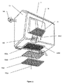
ハンドドライヤ1は、主フード10及びベースプレート11の形態をしたベースマウントを含むハウジングを有する。ベースプレート11は、図1B及び図1Cに最も良く示され、又、図2A及び図2Bにも示されている。
The hand dryer 1 has a housing that includes a base mount in the form of a
図1Bでは、フード10は、ヒンジ12によってベースプレート11に取り付けられている。
In FIG. 1B, the
ヒンジ12は、フード10をベースプレート11から離脱させ又は取り外すことができるように設計されている。これにより、ハンドドライヤ1を簡単な2段階方法で設置することができ、即ち、まず最初に、ベースプレート11を直立した表面、例えば壁に取り付け、次に、フード10をベースプレート11のヒンジに取り付ける。
The
ベースプレート11は、ねじ13、ボルト、又は他の適当な締結機構体によって壁に固定される。
図1Aは、閉鎖位置に配置されたフード10を示しており、これは、ドライヤ1が定位置に設置されたときの配置形態である。
FIG. 1A shows a
図1Bは、開放位置に配置されたフード10を示している。
FIG. 1B shows the
図1Aと図1Bの両方において、ドライヤ1の向きは、これが壁に取り付けられた状態で記載されている。 In both FIGS. 1A and 1B, the orientation of the dryer 1 is described with it attached to the wall.
商業的実施形態では、フード10は、ベースプレート11にロックされ、ロック16Bをロック解除するには図1A及び図1Bで理解されるように、専用のキー16Aが必要である。
In a commercial embodiment, the
空気流
全体の要約として、ドライヤ1を使用にあたって動作させてユーザの手を乾燥させる場合、周囲環境からの空気が、次の順序で、即ち、ハウジング内に引き込まれ又は吸い込まれ、次に加熱され、そして放出される。この空気流の経路は、概念的に、図1Aにおいては矢印200Aで、次に図1Bでは矢印200Bで、最後に図1Aでは矢印200Cで示されている。当然のことながら、ドライヤ1内での空気の実際の流れは、非常に複雑であって乱流状態であり、したがって、矢印200A,200B,200Cは、説明の便宜上単純化されている。
As a summary of the overall air flow, when operating the dryer 1 in use to dry the user's hand, the air from the ambient environment is drawn or sucked into the housing and then heated in the following order: , And then released. This air flow path is conceptually indicated by
空気加熱器
図4では、ドライヤ1は、発熱体300の形態をした加熱手段を備えている。発熱体300は、ファンケーシング400の開口部のところに配置され、図4ではファンケーシング400の別個の下から見た斜視図により明確に示されている。
Air Heater In FIG. 4, the dryer 1 is provided with heating means in the form of a
発熱体300は、ドライヤ1が温風を放出しているときに電気的に昇温されるようになった格子状のワイヤ又はプレートを含む。
The
図1B及び図4に関し、発熱体300は、ハウジング10,11内に位置決めされ、この発熱体は、空気がユーザの手を乾燥させるのに十分に温かくなるよう空気流200Bを昇温させるために用いられる。
1B and 4, the
入口手段
ドライヤ1は、空気を使用の際にハウジング10,11に流入させ、そして、発熱体300に到達するよう移動させる入口手段を有する。
The inlet means dryer 1 has inlet means for allowing air to flow into the
この実施形態では、入口手段は、空気を発熱体300に到達するよう移動させる領域又は通路であると考えられる。
In this embodiment, the inlet means is considered to be a region or passage that moves air to reach the
図1Bでは、入口手段は、図1Bの実施形態では相当な範囲のコンポーネント及び特徴を含む。最初に、入口手段は、空気をハウジングに流入させる補助フィルタ組立体520A,520B,520Cを含む。
In FIG. 1B, the inlet means includes a substantial range of components and features in the embodiment of FIG. 1B. Initially, the inlet means includes
入口手段は、ハウジング10,11の洞穴状内部を更に含む。空気は、補助フィルタ組立体520A,520B,520Cを通り、次にハウジング10,11の洞穴状内部の中に流入する。
The inlet means further includes a cave-like interior of the
入口手段は、ファンケーシング400の側部に設けられた主入口405を更に含む。この主入口405内には、主フィルタ組立体410A,410B,410C(及び以下に説明する他の実施形態)の形態をした主空気伝染細菌フィルタ装置が挿入される。
The inlet means further includes a
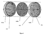
主フィルタ組立体410A,410B,410Cの第1の実施形態の分解組立て図が、図3に示されている。
An exploded view of the first embodiment of the
図4は、主フィルタ組立体がファンケーシング400の主入口405にどこで嵌まり込むかと関連して主フィルタ組立体の実施形態を示している。
FIG. 4 illustrates an embodiment of the main filter assembly in relation to where the main filter assembly fits into the
図4では、主フィルタ組立体は、好ましくは、主入口又は主孔405に直に嵌まり込むベース要素410Aを有する。図7Bでは、ベース要素410Aは、ベース要素を主孔405に嵌合させてこれとロック状態にすることができる幾つかの弾性爪408を備えている。
In FIG. 4, the main filter assembly preferably has a
図3は、主フィルタ組立体410A,410B,410Cの一部の分解組立て図である。
FIG. 3 is an exploded view of a part of the
図3及び図4では、フィルタ材料410Bの形態をした細菌捕捉フィルタ手段が、フィルタホルダ410Cに取り付けられている。フィルタホルダ410Cは、ベース要素410に係合することができる。
3 and 4, a bacteria capture filter means in the form of
フィルタ材料410Bは、フィルタをフィルタホルダ410Cに取り付けるために用いられるスリットを備えている。使用にあたり、フィルタホルダ410Cに設けられた突出ピン411が、図4に示されると共に図7Bで最も良く示されているように、フィルタのスリットを通過する。
The
フィルタホルダ410A,410Cは各々、粗いメッシュ414を有し、このメッシュも又、定位置にあるフィルタ材料410Bの運動を制限する。
ベース要素410A及びフィルタホルダ410Cは、これら部品が差し込み形係合方式で互いに嵌まり合うことができるようにする対応の差し込み取り付け部品を備えている。他の実施形態では、他形式又は他様式の係合機構体、例えば、相互嵌合ピン若しくは圧力嵌め取り付け装置、又はプレス・アンド・ロック(press-and-lock)取り付け装置を用いることができる。
出口手段
乾燥機1は、空気を発熱体300による加熱後に手を乾燥させるために用いられる加熱空気流200Cとして放出させる出口手段を有している。
The outlet means dryer 1 has outlet means for releasing air as a
この実施形態では、出口手段は、空気をこれがドライヤ1から放出されるまで発熱体300から遠ざかって移動させる領域又は通路であると考えられる。
In this embodiment, the outlet means is considered to be a region or passage that moves air away from the
図1Aでは、発熱体300は、フード10の前部に設けられた突出くちばし状開口部14内部に配置されている。それ故、例示の実施形態では、出口手段は、空気が入口手段を通って移動しなければならない距離と比較して、全体として距離がかなり短い。
In FIG. 1A, the
発熱体300を越えて流れた加熱空気は、開口部14を通過したほぼ直後にハウジングから出る。
The heated air that has flowed past the
開口部14は、ユーザの指が発熱体300の加熱部分に触れるのを阻止するグリル15を有している。
The
ファン
ドライヤ1を通る空気流200A,200B,200Cは、図4に示されている回転ファン401の形態をした空気流発生手段によって作られる。ファン401は、ファンケーシング400内部で回転するロータの形態をしている。円形ファン401の内側部分が、図4で理解できる。全体として円形の形をしたファンケーシング400は、円形ファン401を受け入れる。ファン401の回転は、図1Bに示されているモータ430により得られる。一例では、モータは、120ワット、7500rpmの交直両用電動機である。モータ430のケーシングは、細菌がモータ430のケーシングの隙間を介してファンケーシング400中の空気流に入り込むのを回避するよう密閉されている。
The
ファンケーシング400内に設けられた回転ファン401は、空気を空気流として流れるように動かすようになっている。空気流は、最初の補助孔520D及びその補助フィルタ組立体520A,520B,520Cを経てハウジング内に流入し、次に、ハウジング10,11の洞穴状内部を通り、次に、主孔405を通り、そして主フィルタ組立体410A,410B,410Cを通り、ついには、空気流は、発熱体300に達する。次に、ファン401により生じた空気流又は空気の流れが、加熱空気流200Cとしてハウジングから放出され、この加熱空気流は、ユーザの手を乾燥させるために使用できる。
The
主フィルタ装置の配置場所
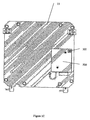
ドライヤ1の入口手段は、主孔405の形態をした少なくとも1つの「主入口」を含む。この主孔は、空気及び細菌がファンケーシング400に入る唯一の入口であることが意図されている。
Location of the main filter device The inlet means of the dryer 1 includes at least one “main inlet” in the form of a
「主入口」という概念は、ドライヤから放出された空気流が全て、最終的には、最初にこの主入口を通過しなければならないことである。この実施形態では、開口部は、ドライヤから出た空気流中の空気が全て或る箇所において文字通りその孔又は入口を通過しなければならない場合、「主孔」又は「主入口」であると定義される。 The concept of “main inlet” is that all the air flow emitted from the dryer must eventually pass through this main inlet first. In this embodiment, an opening is defined as a “main hole” or “main inlet” if all of the air in the air stream exiting the dryer must literally pass through that hole or inlet at some point. Is done.
効果的な細菌捕捉フィルタを1つ又は2つ以上の主入口に配置することにより、ドライヤから出る全ての空気流が細菌捕捉フィルタによって遮られるようになる。 By placing an effective bacteria capture filter at one or more of the main inlets, all airflow exiting the dryer is blocked by the bacteria capture filter.
この実施形態では、主孔405は、ファンケーシング400に設けられている。主孔405は、ファンケーシング400に設けられた開口部内に位置し、したがって、ファンケーシング400に流入する空気が全て、この最終フィルタ410Bを通過しなければならないようになっている。空気流がファンケーシングに流入した後、装置1には唯一の出口14しかない。したがって、この孔405は、「主入口」と見なされる。というのは、これとは別にファンケーシングへの他の通路が存在しないからである。換言すると、最終出口14に通じる他の経路は存在しない。
In this embodiment, the
別法として、「主入口」の定義をより理解しやすくするため、例えば、図1Aの補助入口520Dは、「主入口」と見なすことはできない。というのは、空気が装置に流入する他の多くの仕方が存在するからである。例えば、細菌は、フード10を開いたときに補助フィルタ520Dをバイパスする場合があり、又は、フード10を閉じたときにフード10及びベースプレート11の隙間の中に入る場合がある。例えば、フード10を開いたとき、トイレの細菌含有周囲空気が、装置1の内部に流れ込む。また、入口520Dと最終出口14との間には、装置1の内部に多くの内面が存在し、かかる内面は、数箇月又は数年間の使用により、感染状態になり、細菌源として働く場合がある。補助フィルタ520Bは、他の仕方、例えば、開いたフードを通り又は内面から空気流に入り込むこの外部からの細菌を遮ることはなく、最終の主フィルタ410Bは、かかる外部細菌を止める。これは、補助入口520Dが「主入口」とは見なされず、又、補助フィルタ520Bが「主フィルタ」とは見なされないからである。
Alternatively, for easier understanding of the definition of “main inlet”, for example, auxiliary inlet 520D of FIG. 1A cannot be considered a “main inlet”. This is because there are many other ways in which air can flow into the device. For example, bacteria may bypass the auxiliary filter 520D when the
主孔405の形態をした主入口は、図4で理解できる。図1Bの記載では、この主孔405は、主フィルタ組立体410A,410B,410Cがファンケーシングのこの主孔405内に挿入された状態で示されているので見えにくくなっている。
A main inlet in the form of a
この主フィルタ組立体410A,410B,410Cは、空気流が発熱体300に達する前に空気流を遮る。主孔405は、ドライヤ内の空気流の全てがドライヤから放出されなければならない場合にかかる空気流全てが通過しなければならない空気流中の箇所である。この場合、細菌粒子は、最終的に捕捉され、かくしてファンケーシング400に入るのが阻止される。好ましくは、ケーシング400,430の残部は、空気がモータケーシング430中へ入ることができないように密封されている。
The
主フィルタ装置410A,410B,410Cをファンケーシングへの最終入口箇所のところに配置することにより、この主フィルタ装置は、考えられる最後の防御ラインとして働く。空気流中に残存しているかもしれない細菌は全て主フィルタ410Bによって遮られるようになる。たとえ細菌が予期せぬこととして装置の壁の隙間を通って又は装置内部の長期間にわたる細菌蓄積から機械に入ったとしても、かかる細菌は、出ている空気流200Cによりグリル15から放出することができない。というのは、装置から出る空気流は、最終的には主フィルタ装置410A,410B,410Cを通過しなければならないからである。
By placing the
かくして、主入口の識別及びハウジングへのその最終入口箇所405のところの主フィルタ装置の配設場所は、乾燥装置1から出る空気流200C中の細菌の100%除去及び破壊を達成する装置1の能力に寄与する特徴である。
Thus, the identification of the main inlet and the location of the main filter device at its
先行技術においては、装置内部の内面も又潜在的な細菌源であるということへの取り組みに対して考慮が払われなければ、100%細菌除去の達成は、困難であると考えられる。装置内の全ての内面及び部分は、潜在的な汚染要因物源である。例えば、内部塗装面は、毒素を生じさせる場合があり、更に又、空気流により、デブリが数年にわたる使用後に内部部品から剥がれる場合がある。先行技術においては、非常に初期に空気流路中に位置決めされたフィルタは、フィルタの下流側に位置する内面から細菌が剥がれ落ちるのを防止しようとはしない。 In the prior art, achieving 100% bacteria removal would be difficult unless consideration is given to the approach that the inner surface of the device is also a potential source of bacteria. All internal surfaces and parts within the device are potential sources of contaminants. For example, internal painted surfaces may cause toxins, and airflow may also cause debris to peel from internal components after years of use. In the prior art, a filter positioned very early in the air flow path does not attempt to prevent bacteria from flaking off from the inner surface located downstream of the filter.
それ故、この実施形態では、最終主フィルタ410Bを直接ファンハウジングに設けて空気流中の上流側に位置するこれら外部汚染要因物及び細菌が全てをこれらがファンハウジングに入る前に最終及び主フィルタ装置410A,410B,410Cによって捕捉されると共に遮ることができるようになっている。主フィルタ装置は、空気流が発熱体300及び出口箇所15に達する前の考えられる最後の場所に配置されている。(フィルタをファンハウジングの内部に配置することは不便である。というのは、これは、容易に交換することができないからであり、又、交換が容易でないフィルタは、時間の経過につれて、それ自体汚染源になる場合があるからである)。
Therefore, in this embodiment, the final
この実施形態では、主孔405及び関連の主フィルタ組立体410A,410B,410Cは、全体として装置ハウジング10,11内に配置されている。このようにすることにより、ユーザは、主フィルタ組立体に接近することができず、しかも、許可を受けた係員だけがこれに接近して交換することができるようにする。
In this embodiment, the
他の変形例では、2つ又は3つ以上の主孔405がファンケーシング400に設けられる場合があるが、かかる変形実施形態では、ファンケーシング400に流入した空気が全て、ファンケーシングのこれら1つ又は2つ以上の主孔405を通過しなければならないということが依然として必要である。
In other variations, two or more
この実施形態では、たとえ細菌がハウジング10,11の隙間に入り込んだ場合でも、ファンケーシングに設けられた主フィルタ410Bの配設場所がファンケーシング内に通じる唯一の入口なので、この主フィルタ410Bは、ファンケーシング400に入る細菌を全て遮ることができるようになる。
In this embodiment, even when bacteria enter the gap between the
図1A及び図1Bの実施形態では、主入口405は、空気流発生手段に通じる入口に設けられ、又は、他の変形例では、その実際の配設場所を変更することができる。ただし、空気流発生手段に流入した空気が全て、この最終入口を通過することを条件とする。
これら実施形態では、1つの主孔(又は複数の主孔)は、ファンケーシングに流入した空気流が全てこの主孔を通過しなければならないようにファンケーシング400に設けられ又はこれに結合されているに過ぎない。これは、図1Aの実施形態に示されているように、好ましく且つ最善の場所である。
In the embodiment of FIGS. 1A and 1B, the
In these embodiments, one main hole (or a plurality of main holes) is provided in or coupled to the
実施形態を設計する際の別の要因は、ファンケーシング400への主たる且つ唯一の開口部である主孔は、好ましくは、ドライヤ1の外部から接近可能であってはならないということである。例えば、ファンケーシング400への主孔405は、フード10の外面から接近可能であってはならず、もしそうであれば、許可を受けていないユーザが、ハンドドライヤ装置1の可動部品及び電気的配線部品に接近できるからである。また、これにより、有害物を装置の電動式部品中に挿入し、それどころか、水をファン及びモータ内に浴びせかける機会を荒らしを働く人に与える場合がある。これら全ての可能性により、危害がドライヤ1のユーザに加わる場合がある。
Another factor in designing the embodiment is that the main hole, which is the main and only opening to the
細菌捕捉
細菌は、実際には、極めて微小な顕微鏡的粒子で構成される。本実施形態のドライヤ1は、細菌捕捉フィルタ手段を備えている。換言すると、細菌粒子を捕捉してドライヤ1から放出された空気に細菌粒子が実際に無く又は含まれていないようにする手段が設けられる。焦点は、細菌の殺菌には当てられず、細菌粒子の捕捉に向けられている。
Bacteria capture bacteria are actually composed of very small microscopic particles. The dryer 1 of this embodiment includes a bacteria capturing filter means. In other words, means are provided for trapping the bacterial particles so that the air released from the dryer 1 does not actually contain or contain bacterial particles. The focus is not on sterilization of bacteria, but on the capture of bacterial particles.
この実施形態では、図3において、主フィルタ組立体410A,410B,410Cの細菌捕捉フィルタ手段は、空気流中の細菌粒子の相当多くの部分を遮って捕捉するのに十分な密度のフィルタ材料の繊維状で高密度の全体的に非一様なマトリックスであるフィルタ材料410Bを含む。繊維は、細菌粒子の通過に対する物理的な障害物として働く。
この実施形態では、理想的には、フィルタ材料410Bは、例えば典型的な公衆トイレ施設で定期的に使用されたとすると、1箇月当たりほぼ1回の交換が必要とされることが分かっている。というのは、フィルタ材料中に細菌粒子が蓄積するからである。
In this embodiment, in FIG. 3, the bacteria capture filter means of the
In this embodiment, it has been found that, ideally, the
フィルタ材料
例示の好ましい実施形態では、フィルタ材料は、溶融腐食繊維材料である。腐食繊維が好ましい。というのは、織り方が密な織布又は織物は腐食繊維材料よりも一層空気流を制限する傾向があるので適切さが低いということが判明しているからである。
Filter Material In an exemplary preferred embodiment, the filter material is a melt eroded fiber material. Corrosive fibers are preferred. This is because densely woven or woven fabrics have proved less suitable because they tend to restrict the air flow more than corroded fiber materials.
図1Aの実施形態のフィルタ材料は、以下の特性を備えた材料の腐食ニードルフェルトポリエステル繊維状パッドである。 The filter material of the embodiment of FIG. 1A is a corroded needle felt polyester fibrous pad of material with the following properties:
〔表1〕
重量(gsm) 150 ISO 9073-1: 1989
厚さ(mm) 1.4mm〜1.8mm ISO 9073-2: 1995
引張り強さ(N/50mm): ISO 9073-3: 1989
−縦方向 165
−横方向 165
通気性 2,500 ISO 9230@20cm2200Pa
(l/sec/m 2 )
[Table 1]
Weight (gsm) 150 ISO 9073-1: 1989
Thickness (mm) 1.4mm to 1.8mm ISO 9073-2: 1995
Tensile strength (N / 50mm): ISO 9073-3: 1989
-Vertical direction 165
-Lateral direction 165
Breathability 2500 ISO 9230 @ 20cm 2 200Pa
(L / sec / m 2 )
フィルタ材料の別の好ましいサンプルでは、通気性の判定は、オーストラリア国標準規格AS2001.2.34−90に従って行われた。結果は、フィルタ材料の好ましいサンプルの通気性は、234.7cm3/cm2/秒であり、変動係数は、5.9であった。 In another preferred sample of filter material, the breathability determination was made in accordance with Australian Standard AS 2001.1.2.34-90. The results showed that the air permeability of a preferred sample of filter material was 234.7 cm 3 / cm 2 / sec and the coefficient of variation was 5.9.
フィルタ材料は、全体がランダムな織成マトリックス又はランダムレイ(random lay)を有する溶融ポリエステル繊維状マトリックスである。かくして、この繊維状マトリックスを通過した空気流中の細菌粒子は、ランダム繊維状マトリックスを通ってナビゲートするよう曲がりくねった流路を通過しなければならず、かくして、細菌粒子の各々が繊維のうちの1本に当たってこれによって捕捉され又はこれにくっ付く可能性が増大する。 The filter material is a molten polyester fibrous matrix having an entirely random woven matrix or random lay. Thus, the bacterial particles in the air stream that have passed through this fibrous matrix must pass through a tortuous flow path to navigate through the random fibrous matrix, thus each of the bacterial particles is out of the fiber. This increases the likelihood of hitting or sticking to one of these.
細菌の捕捉を助ける高密度のフィルタと迅速な空気流を確保する密度の低いフィルタの相反する要件の選択には妥協策が見出される場合が多い。 Compromises are often found in the selection of the conflicting requirements of high density filters that help trap bacteria and low density filters that ensure rapid airflow.
問題は次の通りである。即ち、フィルタの密度又は厚さの増大により、一方においては、細菌粒子が一層効果的に捕捉されるが、それと同時に、フィルタを通る空気流が遅くなり、それにより、ファンモータがオーバーヒートする場合がある。したがって、100%細菌遮断という好ましい目的を達成することが望ましい場合、所与の実施形態について特定の動力モータ及びファンに用いられるフィルタ材料の適当な密度を見出すための何らかの実験を行うことが必要な場合がある。例えば、強力な空気流を生じさせる強力なファンでは、より密度が高く且つ(或いは)より厚さが大きなフィルタ材料を用いることができる。 The problem is as follows. That is, increasing the density or thickness of the filter, on the one hand, traps bacterial particles more effectively, but at the same time slows the air flow through the filter, which can overheat the fan motor. is there. Thus, if it is desirable to achieve the desirable goal of 100% bacterial blockade, it is necessary to do some experimentation to find the appropriate density of filter material used for a particular power motor and fan for a given embodiment. There is a case. For example, a powerful fan that produces a strong air flow may use a filter material that is denser and / or thicker.
gsm(1平方メートル当たりのグラム数)で表されたフィルタメッシュ重量は、フィルタメッシュ中の隙間の平均サイズの性状についての見通しを与える。 The filter mesh weight expressed in gsm (grams per square meter) gives a perspective on the average size properties of the gaps in the filter mesh.
例えば、50gsm材料の繊維状マトリックスは、細菌粒子を適度に捕捉するが、50gsm繊維状材料は、ファン401に十分な空気流をもたらさないことが判明した。
先行技術においては、極めて目の細かいフィルタメッシュを選択することにより細菌濾過を達成しようとする傾向が存在する。先行技術の考え方は、魚を捕まえるネットの考え方に良く似ており、この場合、サイズは、細菌のサイズにマッチするほど十分小さくなければならない。これにより、問題が生じる。というのは、メッシュサイズが減少するにつれ、高速で通過する空気流の性能が減少するからである。この問題は、極めて目の細かいフィルタメッシュサイズに付きものの場合がある問題を考慮しないで非常に目の細かい滅菌フィルタに関する公知の先行技術では容易には認識されていない。
For example, a fibrous matrix of 50 gsm material has been found to moderately trap bacterial particles, but 50 gsm fibrous material has not been found to provide sufficient airflow to the
In the prior art, there is a tendency to achieve bacterial filtration by selecting a very fine filter mesh. The idea of the prior art is very similar to the idea of a net catching fish, where the size must be small enough to match the size of the bacteria. This creates a problem. This is because, as the mesh size decreases, the performance of airflow passing at high speed decreases. This problem is not readily recognized in the known prior art for very fine sterilization filters without considering the problems that may be associated with very fine filter mesh sizes.
本発明の実施形態は、相反する要望に関する問題を認識している。一方においては、フィルタメッシュが細菌粒子を捕まえるのに十分であることが望ましいが、他方においては、かかるフィルタメッシュは、これが最適な空気流を妨げるほど小さいものであってはならない。 Embodiments of the present invention recognize problems with conflicting needs. On the one hand, it is desirable that the filter mesh be sufficient to catch bacterial particles, but on the other hand, such a filter mesh should not be so small that it prevents optimal air flow.
本発明の実施形態では、メッシュサイズは、不織布が約150ミクロンの繊維相互間の平均隙間又は細孔を有するという意味で、約150ミクロンウィーブであるものとして選択される。これは、非常に迅速な空気流が達成可能である一方で、細菌を100%捕捉する能力を保持したサイズ範囲にあるものとして広範なフィルタ材料から選択されていた。比較的大きな孔径である150ミクロンウィーブを用いることができる。というのは、このフィルタは、以下に説明するフィルタに施された粘着性の液体被膜と関連して用いられるからである。 In an embodiment of the invention, the mesh size is selected to be about 150 micron weave in the sense that the nonwoven has an average gap or pore between fibers of about 150 microns. This has been selected from a wide range of filter materials as being in a size range that retains the ability to capture 100% of the bacteria while a very rapid air flow can be achieved. A 150 micron weave with a relatively large pore size can be used. This is because the filter is used in conjunction with an adhesive liquid coating applied to the filter described below.
理論により限定するものではなく、150ミクロンウィーブは、細菌を捕捉するための適当なメッシュサイズとして先行技術において認識されていなかったことが考えられる。というのは、150ミクロンウィーブの細孔は、細菌粒子の代表的なサイズよりも極めて大きいからである。しかしながら、本実施形態では、繊維に粘着性の抗菌性液体が塗布されている場合、約150ミクロンに選択されたメッシュサイズは、適切なものになることが認識されている。というのは、大きな孔径は、迅速な空気流を可能にする一方で、細菌が100%繊維のうちの1本に当たり、粘着性被膜によりこれにくっ付くようにする十分に曲がりくねり且つランダムな流れ流路を提供するからである。 Without being limited by theory, it is believed that 150 micron weave was not recognized in the prior art as a suitable mesh size for capturing bacteria. This is because the 150 micron weave pores are much larger than the typical size of bacterial particles. However, in this embodiment, it is recognized that the mesh size selected to be about 150 microns would be appropriate when the fiber is coated with an adhesive antimicrobial liquid. This is because the large pore size allows a rapid air flow while allowing a sufficiently tortuous and random flow flow that allows bacteria to hit one of the 100% fibers and stick to it with an adhesive coating. Because it provides the road.
かくして、選択された約150ミクロンのウィーブは、異なる仕組みを用いて細菌を捕捉する。細菌は、必ずしも、2つの近接した繊維の隙間相互間に捕捉されるわけではない(魚がネットで捕まえられるということの類推により)。これとは異なり、150ミクロンウィーブでの繊維状マトリックスのウィーブは、十分に曲がりくねった経路を提供し、繊維に当たり又はこれと衝突する細菌の確率が極めて高くなることが判明している。また、以下に説明するように、フィルタストランドは、フィルタ繊維に衝突する細菌粒子が空気流に同伴されるのではなく、繊維にくっ付く可能性が高いようにするために、粘着性物質で被覆される。換言すると、フィルタメッシュ又は約150ミクロンでは、繊維中の大きな隙間により、空気流は、フィルタ材料を非常に迅速に通過することができる。それと同時に、150ミクロンの繊維の密度により、空気中の細菌は、空気がフィルタを通って動く際にフィルタスレッドにより捕捉されるようになる。 Thus, the selected approximately 150 micron weave captures bacteria using a different mechanism. Bacteria are not necessarily caught between two adjacent fiber gaps (by analogy that fish are caught on the net). In contrast, the weave of a fibrous matrix with a 150 micron weave has been found to provide a sufficiently tortuous path with a very high probability of bacteria hitting or colliding with the fiber. Also, as described below, the filter strands are coated with a sticky substance so that the bacterial particles impinging on the filter fibers are not likely to be entrained in the air stream but stick to the fibers. Is done. In other words, at a filter mesh or about 150 microns, large air gaps in the fibers allow the air flow to pass through the filter material very quickly. At the same time, the 150 micron fiber density allows airborne bacteria to be trapped by the filter threads as the air moves through the filter.
換言すると、相反する要件であるi)病原菌捕捉と、ii)空気流の速度の両方に取り組むために組み合わされるのは、繊維状材料の性状と繊維に施される粘着性被膜の性状である。 In other words, it is the nature of the fibrous material and the nature of the adhesive coating applied to the fibers that is combined to address both conflicting requirements i) pathogen capture and ii) airflow velocity.
約150ミクロンのフィルタは、当然のことながら、一般用途向けの市場では広く利用されているが、i)100%の病原菌捕捉とii)非常に高い空気流速度の両方を可能にする予期せぬ結果を与えたことは、約150ミクロンのフィルタメッシュの予測しなかった選択である。約150ミクロンメッシュの選択は、大きな孔径が典型的な細菌サイズの何倍にもなるので予想外である。本実施形態に用いられる選択により、この見かけ上大きなフィルタ孔径が粘着性被膜と組み合わされた場合、実際に且つ予想外に、理想的な選択肢になることが認識される。 Filters of about 150 microns are, of course, widely used in the general-purpose market, but unexpectedly allowing both i) 100% pathogen capture and ii) very high airflow rates What gave the result was an unexpected selection of a filter mesh of about 150 microns. The choice of about 150 micron mesh is unexpected as the large pore size is many times the typical bacterial size. The selection used in this embodiment recognizes that this apparently large filter pore size, in combination with an adhesive coating, is actually and unexpectedly an ideal choice.
i)100%病原菌捕捉とii)非常に高い空気流速度を可能にする2重の且つ予想外の利益を依然として達成することができる許容性の上限と下限を150ミクロンマークからのプラス又はマイナス分散の観点で決定する何らかの実験を行うのが良い。 i) 100% pathogen capture and ii) double or unexpected tolerance upper and lower limits from 150 micron mark that can still achieve double and unexpected benefits that allow very high airflow rates It is better to conduct some experimentation that is determined from the viewpoint.
主フィルタ材料410Bは、空気流中の細菌粒子の相当な部分を捕捉してフィルタ中に保持する。かくして、主フィルタ410Bから出た空気流は、空気流がフィルタ410Bに入ったときよりも滅菌度が高い。
The
上記段落では、「保持する」という用語は、細菌のうちの相当な部分がフィルタに入るが、これを出ることができないということを示している。換言すると、主フィルタ410Bから出た空気流は、同一の主フィルタ410Bに入る空気流よりも細菌粒子の数が少ない。
In the above paragraph, the term “hold” indicates that a significant portion of the bacteria enter the filter but cannot leave it. In other words, the air flow exiting the
独立の微生物学的試験により立証された本実施形態の特徴として、フィルタ410Bを出た空気流は、細菌が100%完全に除去されていること又は少なくとも実質的に細菌が除去され且つ100%マークに極めて近い。換言すると、細菌粒子は、単に非活性化され又は殺菌されるのではなく、極めて大幅に空気流から物理的に除去されている。
As a feature of this embodiment, as demonstrated by independent microbiological testing, the air
この実施形態の初期の実験モデルを、種々の微生物による空気汚染が存在していることが確認された工場の男性用トイレで試験した。ドライヤ1から1から出た空気流は、細菌粒子又は病原体が100%無いことが判明した。かくして、この実施形態の細菌捕捉フィルタ手段は、空気流中の細菌を100%捕捉することができ、細菌捕捉フィルタ手段から出た空気流は、100%細菌が存在せず又は実質的にそれに近いものであるようになっている。 The initial experimental model of this embodiment was tested in a factory men's toilet that was confirmed to be air contaminated with various microorganisms. The air stream exiting dryer 1 through 1 was found to be 100% free of bacterial particles or pathogens. Thus, the bacteria capture filter means of this embodiment can capture 100% of the bacteria in the air stream and the air flow exiting the bacteria capture filter means is 100% free of bacteria or substantially close to it. It comes to be a thing.
したがって、100%細菌の無い手の乾燥という目的を達成できる本発明の実施形態は、使い捨てのペーパータオルよりも手を乾燥させるのにより衛生的であるということができる。例えば、100%細菌除去に近いレベルでこのことを達成するモデルは、手術にかかる前に外科医によって使用されるのに適している。 Thus, embodiments of the present invention that can achieve the goal of hand drying without 100% bacteria can be said to be more hygienic to dry hands than disposable paper towels. For example, a model that achieves this at a level close to 100% bacteria removal is suitable for use by surgeons prior to surgery.
かくして、本発明のこの特徴では、ドライヤ1の実施形態は、実際の細菌粒子を捕捉して保持し、それにより細菌がドライヤから出て温かい空気流200C中に入るのを阻止する手段を備える。これは、先行技術のドライヤで用いられる空気フィルタとは概念的に異なっており、かかる空気フィルタは、大きな粒子、例えばダストやごみを濾過して除去するに過ぎず、又、細菌粒子の100%除去の規模で細菌を捕捉するようになっておらず又は意図されていない。かくして、単に「空気フィルタ」を記載した先行技術であっても、これが細菌粒子の実際の捕捉を教示していなければ、一見しただけで細菌捕捉フィルタ手段の先行技術開示として必ずしも取り扱われるべきではない。
Thus, in this aspect of the invention, the dryer 1 embodiment comprises means for capturing and holding the actual bacterial particles, thereby preventing the bacteria from leaving the dryer and entering the
この実施形態の広義の前提は、細菌を効果的に殺菌するために、細菌粒子を捕捉しなければならないということである。これは、まず最初に細菌粒子を捕捉して保持するのではなく、細菌を流れるように動いている空気流中に同伴させながら細菌を殺菌しようとする先行技術の滅菌ドライヤとは異なる取り組み方である。実験において、かかる先行技術のシステムは、まず最初に細菌を捕捉し、次にフィルタ中に動かない状態に保持された捕捉状態の細菌を殺菌する本発明の実験的実施形態と比較して、細菌を空気流から除去する効率が遙かに低いということが判明した。 The broad premise of this embodiment is that bacterial particles must be captured in order to effectively sterilize the bacteria. This is a different approach than prior art sterilization dryers that try to sterilize bacteria while entraining them in a moving air stream, rather than capturing and holding them first. is there. In an experiment, such prior art systems first captured bacteria and then compared to experimental embodiments of the present invention that killed captured bacteria held stationary in the filter. Was found to be much less efficient in removing air from the air stream.
以上要約すると、繊維状マトリックスは、細菌粒子を物理的に捕捉することができ、それと同時に、空気流に与える抵抗が最小限である。それ故、繊維相互間の平均隙間又は細孔は、空気流に与える抵抗が最小限であるように細菌のサイズよりも極めて大きい。また、空気流の曲がりくねった経路又は流路が、繊維状マトリックスによって作られ、細菌粒子がマトリックスの繊維のうちの少なくとも何割かに当たる確率が極めて高くなっている。 In summary, a fibrous matrix can physically trap bacterial particles while at the same time providing minimal resistance to air flow. Therefore, the average gap or pore between the fibers is much larger than the size of the bacteria so that the resistance to airflow is minimal. Also, the tortuous path or flow path of the air flow is created by the fibrous matrix, and the probability that the bacterial particles hit at least some percent of the matrix fibers is very high.
フィルタ材料の例
一例として、本実施形態に用いられるフィルタ材料は、1平方メートル当たり150グラムの多数のランダム繊維を含むカードポリエステルスパンボンドメンブレンである。このフィルタ材料のキャリパ厚さは、1.4〜1.8mmである。150gsmフィルタ材料のこの比較的大きな細孔は、2500l/秒/m2の最大空気速度透過性を可能にする。
As an example of a filter material, the filter material used in this embodiment is a card polyester spunbond membrane containing a large number of random fibers of 150 grams per square meter. The caliper thickness of this filter material is 1.4 to 1.8 mm. This relatively large pore of the 150 gsm filter material allows a maximum air velocity permeability of 2500 l / sec / m 2 .
この材料は、乾燥状態にあるとき、約30〜40ミクロンの平均隙間又は細孔により或る程度の繊維絡みを提供する。かくして、乾燥状態では、この材料は、100%細菌捕捉を達成するのは不適当である。というのは、細菌粒子は、通常、0.3〜30ミクロンであり、ウィルスは、0.01〜0.05ミクロンだからである。それ故、150gsmフィルタ材料は、その乾燥状態では、それ自体100%捕捉率又はこれに近い捕捉率を達成するという目的には適していそうもない。しかしながら、かかる見掛け上大きなメッシュサイズの選択は、繊維に施された粘着性被膜と組み合わされると、予想外にも、100%捕捉率という目的を達成するのに使用でき、しかも、大きな細孔を通る迅速な空気流速度を可能にする。 This material, when dry, provides some degree of fiber entanglement with an average gap or pore of about 30-40 microns. Thus, in the dry state, this material is unsuitable for achieving 100% bacterial capture. This is because bacterial particles are typically 0.3-30 microns and viruses are 0.01-0.05 microns. Therefore, the 150 gsm filter material is unlikely to be suitable for its purpose of achieving 100% capture rate or close to it in its dry state. However, such an apparently large mesh size selection can, unexpectedly, be used to achieve the goal of 100% capture when combined with a tacky coating applied to the fiber, yet with large pores. Allows rapid airflow velocity through.
被覆繊維の追加の粘着性は、150ミクロン細孔からのみ単独で示唆される通常予測される捕捉率の何倍も粒子を捕捉する能力を高める。 The additional tackiness of the coated fibers enhances the ability to capture particles many times the normally expected capture rate suggested solely from 150 micron pores alone.
殺菌性物質:ファイバ中の病原菌の殺菌
好ましい実施形態では、フィルタ材料410Bは、フィルタ材料に捕捉されて保持されている細菌を殺菌することができる殺菌性物質で被覆されている。
Bactericidal substance: sterilization of pathogens in the fiber In a preferred embodiment, the
繊維状マトリックスは、その繊維に施された毒性の殺菌性物質を有し、この毒性の殺菌性物質は、繊維に付着している殺菌性物質に当たった細菌を殺菌することができる。 The fibrous matrix has a toxic bactericidal substance applied to the fiber, and this toxic bactericidal substance can sterilize bacteria that hit the bactericidal substance adhering to the fiber.
かくして、繊維中に捕捉されて保持された細菌の相当の部分は又、フィルタ内で繊維上で殺菌される。(フィルタ中に殺菌剤が設けられていない場合、細菌粒子が捕捉されると、フィルタ材料中に細菌感染が生じる場合がある)。 Thus, a substantial portion of the bacteria trapped and retained in the fiber is also sterilized on the fiber in the filter. (If no bactericidal agent is provided in the filter, bacterial infection may occur in the filter material when bacterial particles are trapped).
この実施形態では、病原菌又は細菌を捕捉し、次にこれらがフィルタ中にある間に殺菌するのが有利である。もしそうでなければ、病原菌を単に捕捉したが殺菌しない場合、フィルタ内の細菌レベルは、経時的に次第に増加する。次に、機械をオフにし、又は稼働中でない場合、フィルタに付着している細菌が成長し、したがって、フィルタそれ自体が細菌源になり、この細菌源は、装置全体にわたって広がって内面を感染するようになる。 In this embodiment, it is advantageous to capture pathogens or bacteria and then sterilize them while they are in the filter. If not, the bacteria level in the filter will gradually increase over time if the pathogen is simply captured but not sterilized. Next, if the machine is turned off or not in operation, the bacteria attached to the filter will grow, thus the filter itself becomes a source of bacteria, which will spread throughout the device and infect the inner surface. It becomes like this.
細菌を殺菌するために用いられる殺菌性物質は、これがフィルタ中に捕捉された細菌の殺菌の役割を果たすことを条件として、液体又はゲルの形態であって良い。 The bactericidal substance used to sterilize the bacteria may be in the form of a liquid or gel, provided that it serves to sterilize the bacteria trapped in the filter.
実際には、この実施形態においては、殺菌性物質は、アルコールを基剤とする液体スプレー内に含ませた状態で繊維状フィルタ材料に吹き付けられる。アルコールが蒸発すると、殺菌性物質は、繊維状ランダムマトリックス上に付着したままである。 In practice, in this embodiment, the bactericidal substance is sprayed onto the fibrous filter material in a liquid spray based on alcohol. As the alcohol evaporates, the bactericidal material remains deposited on the fibrous random matrix.
この実施形態では、殺菌性物質は、液体塗布物質である。殺菌性物質を液体として繊維に塗布すると、この殺菌性物質は、繊維上に粘着性被膜を形成し、この粘着性被膜は、繊維上に見られる殺菌性物質に当たった細菌の捕捉を助ける。粘着性被膜は、衝突した細菌粒子を繊維に物理的に保持することができ、したがって、細菌は、その場所に保持されて殺菌されるようになる。 In this embodiment, the bactericidal substance is a liquid application substance. When the bactericidal substance is applied to the fiber as a liquid, the bactericidal substance forms an adhesive coating on the fiber, which helps capture bacteria that have hit the bactericidal substance found on the fiber. The adhesive coating can physically hold the impinging bacterial particles to the fiber, so that the bacteria are held in place and become sterilized.
多くの殺菌性物質又は液体を用いてフィルタ410B,520B内に捕捉された細菌粒子を殺菌できることは理解されるべきである。この実施形態では、殺菌性物質は、オーストラリア国ビクトリア所在のヘルスガード・コーポレイション・オブ・キャンプベルフィールド(Healthguard Corporation of Campbellfield)により商品コードAFA-BK, 9-260として製造されている。
It should be understood that many bactericidal substances or liquids can be used to sterilize bacterial particles trapped within
この実施形態では、捕捉フィルタ410Bは、1箇月毎に交換されるべきである。というのは、フィルタに付着している抗菌性粘着性物質の効力は、長期にわたりその有効性を維持しないからである。
In this embodiment, the
別の変形例:フィルタ装置
図4の第1の実施形態では、主フィルタ組立体には1つの主フィルタ410Bが設けられている。この第1の実施形態では、抗菌性物質は、フィルタ410Bに当たった細菌を殺菌するが、欠点として、微量の抗菌性物質が空気流中に残る場合があり、フィルタから出て人間活動環境の雰囲気内に入る。これら微量の抗菌性物質は、平均的な人に対して危険である可能性は滅多に無いが、これらは、或る人々、特に、呼吸器疾患又は肺疾患を患っている人々に対してはかなり危険な場合がある。例えば、嚢胞性線維症を患っている人は、微量であっても雰囲気中の毒性物質により危害を受ける場合がある。
Another Modification: Filter Device In the first embodiment of FIG. 4, the main filter assembly is provided with one
抗菌性液体は、典型的には病毒細胞を100%殺菌できる効力レベルにあるとき、人に対して非常に毒性が高く且つ有害である傾向がある。例えば、これは、潜在的に目の刺激物である。 Antibacterial liquids tend to be very toxic and harmful to humans, typically at a potency level that can kill 100% of diseased cells. For example, this is potentially an eye irritant.
殺菌性物質は、細菌を殺菌するために毒性が高いことが必要であるが、好ましくは、毒素は、空気流から除去される必要がある。 The bactericidal substance needs to be highly toxic in order to sterilize the bacteria, but preferably the toxin needs to be removed from the air stream.
微量の毒性物質を空気流から除去するため、図7A及び図7Bは、毒性の殺菌性物質を有する主繊維状フィルタ410Bに続き連続して木炭又はカーボンフィルタ手段が設けられていることを示す。この実施形態では、木炭フィルタ手段は、木炭又はカーボン粒子が注入された木炭注入繊維状又は多孔質フィルタ材料410Dの形態をしている。
In order to remove traces of toxic substances from the air stream, FIGS. 7A and 7B show that a charcoal or carbon filter means is provided in succession following the main
木炭注入フィルタ材料410B中の木炭又はカーボン粒子は、空気流を遮ってこの空気流から捕捉フィルタ410Bに施された被膜に由来する毒性の殺菌性物質を除去する。これにより、主フィルタ組立体から出た空気流が実質的に細菌粒子を含まないだけでなく、微量の殺菌性物質を含まないようになる。
The charcoal or carbon particles in the charcoal
上述したように、殺菌性物質を空気流から除去することにより、肺の状態が非常に敏感な人が存在する人間活動環境、例えば病院内で使用することができる。 As described above, by removing the bactericidal substance from the air stream, it can be used in a human activity environment, such as a hospital, where there are people with very sensitive lung conditions.
また、殺菌性物質が空気流から除去されるので、これにより、オプションとして、第1の繊維状フィルタ410Bに付着している非常に効力の高い殺菌性物質を利用することができる。これは、次に木炭フィルタ410Dが設けられていない場合、空気流中の高い毒性が周囲環境内の人々を害する場合があるというのではないかと心配して、極めて毒性の高い物質を第1のフィルタ410B内に用いるのを控えることが必要であるからである。これに対し、次に木炭フィルタ410Dが設けられている場合、第1のフィルタ410B内に非常に毒性の高い物質を用いることにより、装置は、その殺菌性能において、高い効率を達成できる。この実施形態では、このように毒性の非常に高い物質を用いることができるということは、木炭フィルタが設けられていることにより、装置1から出た細菌が100%除去された空気流を達成することができるということに寄与する。
Also, since the bactericidal material is removed from the air stream, this can optionally utilize a highly effective bactericidal material adhering to the first
さらに、理論によって束縛されるものではないが、木炭は、空気流が木炭注入フィルタ410Dを通って流れているときに空気流を再酸素化することが考えられる。
Further, without being bound by theory, it is conceivable that the charcoal reoxygenates the airflow when the airflow is flowing through the
かくして、木炭は、第1に、毒性抗菌性化学物質を除去する役割と、第2に、空気流を再酸素化する役割の2重の役割を有すると考えられる。木炭は又、空気流から悪臭及び異臭を除去すると考えられる。 Thus, charcoal is thought to have a dual role of first removing toxic antimicrobial chemicals and secondly reoxygenating the air flow. Charcoal is also believed to remove malodors and off-flavors from the air stream.
この実施形態では、繊維状フィルタ材料410Dには木炭粒子又は粉末が注入されるが、他の変形例では、多孔性の高い木炭又は木炭注入材料片も又使用できる。ただし、多孔性が空気流速度を実質的に損なわないほど十分であることを条件とする。
In this embodiment, the
この実施形態では、木炭フィルタ410Dは、細菌を捕捉して殺菌するために主として用いられているわけではない。細菌の捕捉及び殺菌のステップは、第1の捕捉フィルタ410Bで行われる。それ故、捕捉フィルタ410Bからの空気流は、これが木炭フィルタ410Dに入った時点で100%の細菌除去レベル又は少なくとも事実上そのレベルに達するようになる。
In this embodiment, the
事実、木炭又はカーボンは、細菌を捕捉して殺菌する上で低級材料であると考えられる。理論により束縛されるものではないが、木炭は、殺菌性物質を配置すべき基体ほど適当ではないと考えられる。というのは、恐らくは、殺菌性物質は、殺菌性物質を細菌を殺菌するのに利用できる表面上に付着させたものではなく、木炭粒子内部に吸収されるからである。また、木炭粒子は、この実施形態では液体又は液体塗布物質である殺菌性物質を汚染する場合があると考えられる。要約すると、この実施形態の木炭フィルタ410Dは、細菌を殺菌するステップを行うようにはなっていない。
In fact, charcoal or carbon is considered a lower material in capturing and sterilizing bacteria. Without being bound by theory, it is believed that charcoal is not as suitable as the substrate on which the disinfectant material is to be placed. This is probably because the bactericidal substance is absorbed inside the charcoal particles, not the bactericidal substance deposited on a surface that can be used to sterilize bacteria. Further, it is considered that the charcoal particles may contaminate a bactericidal substance that is a liquid or a liquid coating substance in this embodiment. In summary, the
木炭粒子410Dは、この実施形態では、粘着性の抗菌性液体被膜を備えていないので、空気流からの細菌の100%除去は、空気流が木炭フィルタ410Dに達する前に達成されるべきである。もしそうでなければ、このことは、幾分かの細菌が木炭フィルタに達し、この細菌は、空気流が動作していないときに増殖する場合のあることを意味している。これにより、木炭フィルタは、経時的に細菌源に変化する場合がある。それ故、細菌の100%除去は、空気流が木炭フィルタに達する前に起こらなければならない。
Since the
細菌が入ることができないフィルタハウジング
図7Aの第2の実施形態では(図4と同様な仕方で)、フィルタ組立体のベース要素410Aは、ファンケーシングの主入口又は主孔405に直接嵌まり込むようになっている。
Filter Housing Incapable of Entering Bacteria In the second embodiment of FIG. 7A (in a manner similar to FIG. 4), the
図7Aの分解組立て図では、第1のフィルタホルダ410Cは、ベース要素410Aに嵌まり、次に、第2のフィルタホルダ410Eに嵌まり、この第2のフィルタホルダは、第1のフィルタホルダ410Cに嵌まる。
In the exploded view of FIG. 7A, the
図7Bは、図7Aのコンポーネントを組立て状態で示している。組立て状態の部品は、差し込み形係合手段と共に嵌合する。ただし、他の形態の取り付け機構の使用が他の実施形態において可能である。 FIG. 7B shows the components of FIG. 7A in an assembled state. The assembled parts are fitted together with plug-in engagement means. However, the use of other forms of attachment mechanisms is possible in other embodiments.
図7Bでは、矢印409は、装置1が使用中であるときの空気流の方向を示している。図7Bでは、フィルタ装置は、フィルタバリヤ手段を備え、このフィルタバリヤ手段は、この実施形態では、フィルタホルダの壁を有し、これらフィルタホルダは、組み合わせ時に、互いに非常に緊密に嵌合する。フィルタ装置は、ベース要素410Aの下縁部とファンハウジングのインターフェイスにより作られるバリヤを更に有する。
In FIG. 7B, the
フィルタホルダ410C,410Eの壁は、使用の際に互いに嵌められると、主捕捉フィルタ410B及び木炭フィルタ410Dを収容するのに役立つ。フィルタバリヤ手段の正味の効果は、フィルタ410B,410Dのための細菌不透過性バリヤとなることにある。この効果的な細菌不透過性バリヤは、フィルタ410B,410Eを装置の内部から分離する。これが意味することは、空気流が装置1中に吹き込まれているときやそうでないときであっても、装置内部の細菌又は他の汚染要因物は、流入空気流に直接向いた主フィルタ410Bのフェースを介してフィルタ装置に入ることができるに過ぎない。汚染要因物及び細菌は、フィルタ装置の他の部分又は継手を通過することができない。
The walls of the
図1A〜図4の実施形態では、空気伝染細菌フィルタ装置410A,410B,410C,410D,410Eは、全体が、装置1の内部に配置される。 In the embodiment of FIGS. 1A to 4, the airborne bacterial filter devices 410 </ b> A, 410 </ b> B, 410 </ b> C, 410 </ b> D, 410 </ b> E are disposed entirely inside the device 1.
ベース要素410Aとフィルタハウジング410C,410Eを互いに嵌め合わせると、細菌は、これらコンポーネント410A,410C,410Eの緊密な嵌合に起因して得られる細菌不透過性ワイヤによりコンポーネント410A,410C,410Eの相互当接箇所を通ってフィルタ装置の内部に入ることができない。これは、潜在的に装置1の内面は、どの機械の場合も同様、これらの部品の構成材料からであるにせよ本明細書において説明する安全防護策にもかかわらず機械に入り込む細菌からのいずれであるにせよ、潜在的な汚染要因物源であるので有利である。それ故、細菌不透過性バリヤは、フィルタ組立体(410A〜410E)の側部又は継手を通る細菌の入り込みを阻止する。
When the
また、同じ細菌不透過性ワイヤは、フィルタ装置内部の生きている細菌が装置をオフにしたとき又は空気流を発生させていないときに装置の内部に逃げ込むのを阻止する。例えば、細菌は、図1Aのグリル15を通って入る場合がある。例えば、装置が使用されていないとき、細菌不透過性バリヤは、細菌が装置の内部に入るのを阻止する。これは、装置の内部それ自体が最終的に、細菌源になるのを阻止する(機械をオフにしたとき、主フィルタ410Bは、反対側の端部通路14を介して入った細菌が、装置の内部領域に達するのを阻止する。装置をもう1度オフにして使用すると、端部通路14内の細菌は、発熱体300からの熱によって殺菌される傾向がある)。
The same bacteria-impermeable wire also prevents live bacteria inside the filter device from escaping into the device when the device is turned off or when no airflow is generated. For example, bacteria may enter through the
フィルタ装置の表面内への細菌不透過性バリヤのこの形成は、可能な限り細菌が装置の内部に阻止するよう個々に且つ(或いは)組み合わせ状態で作用する装置の他の特徴部の機能を補完する。これは、乾燥装置1の内部がそれ自体細菌源になる状況を回避し又は最小限に抑えるためである。 This formation of a bacteria-impermeable barrier in the surface of the filter device complements the function of other features of the device that act individually and / or in combination to prevent bacteria from entering the device as much as possible. To do. This is to avoid or minimize the situation where the interior of the drying apparatus 1 itself becomes a source of bacteria.
装置の内部への細菌の入り込みを最小限に抑えるこれら特徴部は、空気流からの100%の細菌除去を達成する装置1の能力に寄与する。換言すると、装置が空気流を発生させていない場合であっても、内部への細菌の入り込みを阻止することは、装置が、全体として100%の細菌除去という目的を達成できるかどうかに影響を及ぼす場合のある別の要因である。 These features that minimize the entry of bacteria into the interior of the device contribute to the ability of the device 1 to achieve 100% bacteria removal from the air stream. In other words, preventing bacteria from entering the interior, even when the device is not generating airflow, will affect whether the device can achieve its overall goal of 100% bacteria removal. Another factor that may be affected.
上述したように、主フィルタ装置410A〜410Eは、この実施形態では、ファンハウジング400への最終入口箇所のところに位置決めされると共に配置されている。この事実と合わせて、主フィルタ装置のために細菌不透過性バリヤを設けることにより、細菌が主フィルタ410Bの前部を除き且つこれを通ってしか、フィルタ組立体中の隙間又は継手を通って主孔405を通過することができないようになる。
As described above, the
他の変形例では、フィルタ組立体のコンポーネントを互いに嵌合させる機構体は、いったん嵌合すると、コンポーネントをユーザによっては互いに引き離すことができないように設計されているのが良い。或る形態のロック機構体を提供することができる。これは、ユーザが、不注意にフィルタ組立体を開き、かくして、この中に入っている細菌を放出させないようにするためである。かかる実施形態の意図は、フィルタ組立体410A,410E全体を一体ユニットとして定期的に交換することにある。この実施形態では、フィルタ組立体を1箇月に少なくとも1回交換することが推奨される。
In other variations, the mechanism for fitting the components of the filter assembly together may be designed so that once fitted, the components cannot be separated from each other by the user. Some form of locking mechanism can be provided. This is to prevent the user from inadvertently opening the filter assembly and thus releasing the bacteria contained therein. The intent of such an embodiment is to periodically replace the
注目されるように、幾つかの場合において、特に、非医学的周囲環境においては、厳密に言えば、木炭フィルタを用いることは必要ではない。一般的な健康状態の人々は、周囲大気中に出て行く空気流中の少量レベルの殺菌性物質を許容できる。 As noted, in some cases, particularly in non-medical surroundings, it is not strictly necessary to use a charcoal filter. People in general health can tolerate small levels of bactericidal substances in the air stream exiting into the surrounding atmosphere.
一体ユニット:フィルタ及びそのコンポーネントの交換及び処分
図3、図7A、図7B、図8A、図8B、及び図1Bから、フィルタ装置は、組み立て状態において、一体且つ単一のユニットの形態をしている。換言すると、フィルタ装置の関連のコンポーネントは全て、単一の交換可能且つ使い捨て可能なユニット内に収納される。主フィルタ410Bが捕捉されて殺菌された細菌粒子で一杯になり始めると、主フィルタ装置全体を一体物として取り外して交換するのが良い。これは、主フィルタ組立体を楽に交換することができることにより、フィルタが捕捉されて殺菌された細菌粒子で詰まり始めたときに主フィルタ装置それ自体が細菌源にならないので有利である。交換が必要なのは繊維状フィルタ材料だけでなく、細菌で汚染された周囲コンポーネントである。かかる利点は、コンポーネントが別体のコンポーネントとして機械の周りに散在している先行技術の装置では得られない。
Integral unit: replacement and disposal of the filter and its components From FIGS. 3, 7A, 7B, 8A, 8B and 1B, the filter device in the assembled state is in the form of an integral and unitary unit. Yes. In other words, all relevant components of the filter device are housed in a single replaceable and disposable unit. When the
一体ユニット:装置の内面の交換及び処分
このように単一ユニットを取り外して交換できることは、別の観点で理解できる。これにより、フィルタ要素410B,410Dの交換が可能になるだけでなく、まさに重要なこととして、これにより、最終孔405の最終入口箇所に最も近い装置1の「内面」412の取り外し及び交換が可能である。これにより、これら内面412はそれ自体、数箇月又は数年間の使用にわたっても、細菌又は他の汚染要因物で覆われた状態にはならない。
Integral unit: replacement and disposal of the inner surface of the device It can be understood from another perspective that a single unit can be removed and replaced in this way. This not only allows the
これにより、装置の設計を装置が新品になった場合に果たすその潜在的性能ではなく、数年間の使用後におけるその潜在的な性能について評価しなければならないことが認識される。数年間経つと、機械の内面も又、細菌で汚染された状態になる場合がある。これは、長年にわたって働いている場合がある装置の長期間の使用にわたり空気流から100%の細菌除去を達成する困難性に別の要因を追加する。 This recognizes that the design of the device must be evaluated not for its potential performance when the device is new, but for its potential performance after several years of use. After several years, the inner surface of the machine can also become contaminated with bacteria. This adds another factor to the difficulty of achieving 100% bacteria removal from the airflow over the long term use of the device that may have worked for many years.
かくして、最終孔405の最も近くに位置する装置の重要な内面を交換できることは、この実施形態において、単に新品の装置ではなく、数年間の使用にわたり100%の細菌除去を達成することができることに寄与する別の要因である。
Thus, the ability to replace the critical inner surface of the device located closest to the
先行技術の装置では、機械の周りに散在したコンポーネントは場合によっては取り外し可能であるが、内面を交換することは非常に困難である。したがって、本実施形態では、主フィルタ装置内に作られたこの密閉環境を単一ユニットとして取り外して交換できるということは、利点である。最終孔に通じる重要な内面を容易に交換することができる。これにより、最終捕捉フィルタ410Bの下流側に位置する内面はそれ自体、時間の経過につれて、細菌源にはならないようになる。
In prior art devices, components scattered around the machine can be removed in some cases, but it is very difficult to replace the inner surface. Therefore, in this embodiment, it is an advantage that this sealed environment created in the main filter device can be removed and replaced as a single unit. The critical inner surface leading to the final hole can be easily replaced. This prevents the inner surface located downstream of the
図7B、図8B、図9A、及び図9Bでは、主捕捉フィルタ410Bと木炭注入フィルタ410Dは、容積隙間413の形態をした容積部によって分離されている。隙間413は、細菌不透過性バリヤ内に密封されている。容積隙間413は、空気流が捕捉フィルタ410Bを出た後に入る一時的行き先として働く。理論によって限定されるものではないが、この局限された容積隙間413は、空気乱流及び空気流速度の減少を増大させる場合のある広い洞穴状容積部全体にわたり空気流を拡散させるのではなく、空気流を局限された領域内に維持するのを助ける。
In FIGS. 7B, 8B, 9A, and 9B, the
主捕捉フィルタ410Bと木炭注入フィルタ410Dは、空気流が通過しない場合、一般に、互いに平行であり、これら相互間の容積部が平らであって且つ平面状になるようになっている。
The
空気流は、主捕捉フィルタ410Bから出て空気流がフィルタ手段の各の表面に実質的に垂直になるような仕方で木炭注入フィルタ410Dに入る。
The air flow exits the
図7Aでは、各フィルタコンポーネントのリムの高さは、各フィルタコンポーネント相互間の隙間413の距離を定める。フィルタ片相互間の距離は、空気がフィルタ装置全体を通って流れることができる能力に影響を及ぼすことが考えられる。これは、隙間無くフィルタ材料の単一の厚手のサンドイッチとして互いに配置された同一のフィルタ材料410B,410Dが、空気流の同一の速度の実現を可能にしないからである。
In FIG. 7A, the rim height of each filter component defines the distance of the
木炭フィルタ410Dは、比較的捕捉フィルタに近接して位置すべきであり、したがって、主フィルタ410Bからの抗菌性毒性物質の実質的に全てを遮ることができるようになる。そうでない場合、木炭フィルタ410Dが、捕捉フィルタ410Bから非常に長い距離だけ離される場合、数年間の期間が経過すると、主捕捉フィルタ410Bと木炭注入フィルタ410Dとの間の装置の内面には、毒性の抗菌性化学物質の定常的な蓄積が生じている場合がある。かくして、隙間413ができるだけ小さいことは、利点である。隙間413が小さいことにより、主フィルタ410Bから出る空気流は、毒性抗菌性液体が装置の内面に被着する可能性がほとんど無い状態で、木炭フィルタ410D内にすぐと言っていいほど早く入ることになる。
The
物質の放出
大まかに再検討すると、空気流は、細菌が繊維に塗布されている抗菌性液体により捕捉されて殺菌される捕捉フィルタ410Bを介してフィルタ装置に入る。次に、連続して、フィルタ410Bから出た空気流は、木炭注入フィルタ410Dに入り、ここで、空気流中の微量の抗菌性液体が除去される。
Roughly revisiting the release of the substance , the air stream enters the filter device via a
図8A及び図8Bの第3の実施形態では、2つのフィルタ410B,410Dの後に、第3のハウジング410G内に保持された放出フィルタ410Fの形態をした放出フィルタ手段が設けられるのが良い。
In the third embodiment of FIGS. 8A and 8B, a discharge filter means in the form of a
この放出フィルタ410Fの目的は、何らかの利点を有する或る放出可能な物質を空気流中に加え又は注入することにある。例えば、有益な放出可能な物質は、ユーザに空気で運ばれる仕方で投与できる医薬品であるのが良い。一例では、医薬品は、喘息で苦しんでいる人々によって使用される薬剤であるのが良い。代表的には、喘息で苦しんでいる人々は、薬剤蒸気を吸い込む吸入器を用いるが、本発明の実施形態を利用すると、その薬剤を周囲大気中に注入することができ、その結果、医薬品を微量の状態で連続的に吸い込むことができるようになる。この方式は、他の呼吸器疾患、例えば気管支炎や静脈洞炎と関連して利用できる。潜在的に、人々が蒸気を吸い込むことによって治療される疾患は、その物質を空気中に放出することにより緩和することができる。
The purpose of this
変形例として、有利な放出可能物質は、フレグレランスであっても良い。これは、装置1が不快の臭いのある環境、例えば、芳香剤を雰囲気中に注入する必要のある公衆トイレで用いる場合に有用である。これは、特にアロマテラピーの分野に利用できる。 As an alternative, an advantageous releasable substance may be fragrance. This is useful when the device 1 is used in an unpleasant odor environment, such as a public toilet where fragrances need to be injected into the atmosphere. This can be used especially in the field of aromatherapy.
医療分野又は他の洗面所で用いられるハンドドライヤの場合、主フィルタ410Bからの毒性の高い殺菌性物質が好ましくは空気流から除去されるべきであっても、この次の放出フィルタ410Fは、毒性の低い抗菌性物質を放出することができ、この抗菌性物質は、捕捉フィルタ410Bに見られる毒性の高い物質と比較して効力が低い。この毒性の低い物質を手を乾かしながらユーザの手に差し向けるのが良い。これにより、手の追加の抗菌性処理が可能になる。
For hand dryers used in the medical field or other toilets, this
この実施形態では、放出フィルタ410Fから放出された毒性の低い抗菌性物質も又、端部開口部14を介して装置1に入る量の細菌を殺菌し又は最小限に抑える追加の役割を果たす。
In this embodiment, the less toxic antibacterial material released from the
上述したように、有益な放出可能物質は各々、化学物質放出剤と組み合わせて使用できる。 As noted above, each of the beneficial releasable materials can be used in combination with a chemical release agent.
ばたつきフィルタ
図9A及び図9Bは、フィルタがこれらのフィルタハウジング内に設けられた実施形態を示しており、図9Aは、空気流が無い場合であり、図9Bは、空気流が通過する場合である。
Flapping Filters FIGS. 9A and 9B show an embodiment in which filters are provided in these filter housings, FIG. 9A shows no air flow, and FIG. 9B shows the air flow passing through. is there.
この実施形態では、上述したフィルタは、ピン411にルーズに取り付けられた平らなフィルタ材料片の形態をしている。フィルタピンにルーズに取り付けることは、フィルタが図9Bに概略的に示されているように空気流中でばたつくことができるようになっていることである。理論により束縛されるものではないが、放出フィルタ410Fのこのばたつきは、放出可能な物質をフィルタ410Fの繊維から空気流中に放出するのを助けると考えられる。
In this embodiment, the filter described above is in the form of a flat piece of filter material loosely attached to the
許容可能なフィルタ順序及び組み合わせ
本発明の種々の実施形態は、フィルタの或る範囲の許容可能な順序及び(又は)組み合わせを有することができる。
Various embodiments of acceptable filter order and combination present invention can have an acceptable order of a range of filters and (or) combination.
フィルタ装置の全ての実施形態では、主細菌捕捉フィルタ410Bが、必要不可欠である。
In all embodiments of the filter device, the main bacteria capture
或る特定の医療環境に関し、捕捉フィルタ410Bの次に木炭注入繊維状フィルタ410Dを設けることが好ましく、主捕捉フィルタ410Bに用いられる微量の毒性の高い殺菌性物質に悪影響を受ける場合のある人々が存在している他の人間活動環境内においても同様である。微量の毒性殺菌性物質の悪影響を受けやすい多くの人々が存在していることは滅多に無い他の環境では、木炭注入繊維状フィルタ410Dを省いても良い。例えば、かかる場合、放出フィルタ410Fは、順序の中の次のフィルタとして捕捉フィルタ410Bの次に位置しても良い。
For certain medical environments, it is preferable to provide a charcoal-injected
また、他の環境では、放出フィルタ410Fが不要な場合があり、この場合、捕捉フィルタ410Bだけを設け、必要に応じ木炭注入繊維状フィルタ410Dを配置すると十分である。
In other environments, the
フィルタ順序及び組み合わせ:4つのフィルタ
図8C及び図8Dは、フィルタ装置が連続した4つのフィルタ410B,410D,410F,410FFを有する第4の実施形態を示している。
Filter Order and Combination: Four Filters FIGS. 8C and 8D show a fourth embodiment in which the filter device has four
図8C及び図8Dでは、フィルタ装置中の空気流は、まず最初に、主捕捉フィルタ410B及び木炭注入フィルタ410Dに遭遇する。これらの次に、2つの放出フィルタ410F,410FFが設けられている。
8C and 8D, the air flow in the filter device first encounters the
この実施形態では、2つ又は3つ以上の放出フィルタ410F,410FFが設けられる場合、各放出フィルタは、好ましくは、互いに異なる有益な放出可能物質を収容する。 例えば、順序中の次のフィルタ410Fは、フレグランス又は香水を空気中に放出するのが良く、他方、順序中の最後のフィルタ410FFは、毒性の低い抗菌性物質を放出するのが良い。
In this embodiment, if two or
したがって、図8Cの4つのフィルタ形実施形態では、次の通りである。 Thus, in the four filter-type embodiments of FIG. 8C:
i)空気流中の細菌は、フィルタにより捕捉され、第1のフィルタ410Bに塗布されている有毒の毒性の高い抗菌性物質により殺菌され、
ii)有毒抗菌性物質は、木炭注入フィルタ410Dにより空気流から除去され、
iii)最後から2番目の放出フィルタ410Fからのフレグランス又は香水が、蒸発して空気流中に入れられ、
iv)ミスト状の緩和な抗菌性物質が最後の放出フィルタ410FFにより空気流中に放出され、したがって、装置から出る空気流は、緩和な非毒性抗菌性物質を含むようになる。
i) Bacteria in the air stream are captured by the filter and sterilized by the toxic and highly toxic antibacterial substance applied to the
ii) Toxic antibacterial material is removed from the air stream by the
iii) The fragrance or perfume from the
iv) A mist-like mild antibacterial substance is released into the air stream by the last release filter 410FF, so that the air stream exiting the device will contain a mild non-toxic antibacterial substance.
注目されることとして、物質が完全に又は実質的に空気流中に蒸発することにより或る物質が空気流中に放出される。これとは対照的に、微粒子又は微細なミスト状の液体として空気流中に放出される他の物質がある。例えば、上述の例では、香水又はフレグランスが、空気流中に蒸発する可能性が多分にあり、これに対し、或る種類の緩和な抗菌性物質を空気流中に放出することは、空気流に入る微細なミストの形態で起こる可能性が多分にある。 It is noted that some material is released into the air stream as it evaporates completely or substantially into the air stream. In contrast, there are other substances that are released into the air stream as fine particles or fine mist-like liquids. For example, in the above example, perfumes or fragrances are likely to evaporate into the air stream, whereas releasing certain mild antimicrobial substances into the air stream There is probably the possibility that it occurs in the form of a fine mist that enters.
したがって、2つ又は3つ以上の放出フィルタ410F,410FFが設けられる場合及びこれらのうち一方が蒸発性物質を有し、他方がミストを形成する物質を有する場合、空気流は、まず最初に、蒸発性物質を含むフィルタ410Fに遭遇し、次に、ミストを形成する物質を含むフィルタ410FFに遭遇することが好ましい。
Thus, if two or
このような順序及び配置が推奨されるが、その理由は、ミスト形成物質が最後から2番目のフィルタ(図8Aでは410F)に塗布された場合、ミストは、周囲環境中に放出されるのではなく、最後のフィルタ(410FF)上に捕捉され又は集まる可能性が多分にあるからである。 Such an order and placement is recommended because if the mist forming material is applied to the penultimate filter (410F in FIG. 8A), the mist will not be released into the surrounding environment. This is because there is probably a possibility of being captured or collected on the last filter (410FF).
許容可能なフィルタ順序を保証するフィルタ順序機構体
フィルタ装置中のコンポーネントが所望の順序で互いに配置され又は嵌合されるようにするため、フィルタホルダは各々、所定の許容可能な順序でのみ別のフィルタホルダと係合できる機構体を備える。フィルタホルダ410C,410E,410Gは各々、フィルタを上述の順序でしか互いに取り付けることができないような取り付け順序手段を備えている。
Filter ordering mechanism that guarantees an acceptable filter order. In order to ensure that the components in the filter device are arranged or mated together in a desired order, each filter holder is different only in a predetermined acceptable order. A mechanism that can engage with the filter holder is provided. The
各フィルタハウジングに設けられた取り付け順序手段は、許容可能な順序のうちの1つにおいて、次に位置するフィルタハウジングに設けられた対応の輪郭としか正確に合致しない異形輪郭の形態をしている。図7Bでは、取り付け順序手段では差し込み形マウントの形態をしている。ハウジング410C,410E,410Gの各々に対する差し込み形マウントの寸法及び位置は、上述したように、受け入れることができない組み合わせが起こる可能性が無いように設計されている。
The mounting order means provided on each filter housing is in the form of a profiled contour that exactly matches the corresponding contour provided on the next located filter housing in one of the allowable orders. . In FIG. 7B, the mounting order means is in the form of a bayonet mount. The dimensions and position of the bayonet mounts for each of the
例えば、フィルタ装置の実施形態は、順序中の第1のフィルタである木炭注入繊維状フィルタ410Dを備えることができない。それ故、フィルタハウジング410C,410E,410Gは、許容可能な組み合わせにおけるフィルタハウジングの別なものとしか合致することができず又は連結することができないコネクタを備えた状態で設計されている。
For example, an embodiment of the filter device cannot include a charcoal injected
例えば、許容可能な組み合わせは、図7Bに見られ、この場合、主フィルタハウジング410Cの後部は、木炭注入フィルタのためのハウジング410Dの前部に合致し又はこれと結合することができる。
For example, an acceptable combination can be seen in FIG. 7B, where the rear of the
他の実施形態では、取り付け順序手段は、1つのフィルタハウジングに設けられ、対応のピン穴が設けられた場合にフィルタハウジングの別のものとしか合致することができないピンの形態をしていても良い。ピン及びピン穴の配設場所は、許容可能な結合順序のみが可能であるように定められる。 In other embodiments, the mounting order means may be in the form of a pin that is provided in one filter housing and can only match another in the filter housing when provided with a corresponding pin hole. good. The locations of the pins and pin holes are determined so that only an acceptable coupling order is possible.
フィルタホルダの各々が許容可能な順序で互いに取り付けられた場合、フィルタホルダは、互いに組み合わさって上述した細菌不透過性バリヤを形成する。 When each of the filter holders are attached to each other in an acceptable order, the filter holders combine with each other to form the bacterial impervious barrier described above.
フィルタホルダは又、これ又上述した単一のスタックを形成する許容可能な順序で互いに嵌まり合う。 The filter holders also fit together in an acceptable order that also forms the single stack described above.
1つ又は複数の補助フィルタ
図1A及び図1Bの実施形態では、主フィルタ組立体410A,410B,410C及び更に好ましくは410D〜410Gに加えて、入口手段が、主フィルタ装置410A〜410E/Gと直列に配置された1つ又は2つ以上の補助フィルタを更に有することが好ましい。
One or more auxiliary filters In the embodiment of FIGS. 1A and 1B, in addition to the
図1Aの実施形態では、補助フィルタ520Bは、空気流中の細菌の数を部分的に減少させるが、空気流の全てが補助フィルタを通るわけではない。例えば、この実施形態では、フード10とベースプレート11との間の隙間を密封するゴムストリップが設けられていない場合、幾分かの空気流は、これら隙間を通ってドライヤ1に入ることができ、その結果、隙間を通る細菌の入り込みを可能にする。これは、この実施形態では、外部フィルタ520Bが単に「補助フィルタ」と見なされているからである。
In the embodiment of FIG. 1A, the
空気流の維持
1つ又は2つ以上の補助入口520Dは各々、細菌捕捉フィルタ手段(520B)を備えている。その理由として、2つ以上のフィルタを設けると、細菌が通過しなければならないフィルタ材料の全体的な組み合わせ「厚さ」が増大し、かくして、細菌がフィルタ材料により捕捉される可能性が高くなるからである。
Maintaining Air Flow One or more auxiliary inlets 520D each comprise a bacteria capture filter means (520B). For that reason, providing more than one filter increases the overall combination “thickness” of filter material that the bacteria must pass through, thus increasing the likelihood that the bacteria will be trapped by the filter material. Because.
図1A及び図1Bの実施形態では、ハウジング10,11に流入した空気は、一連の孔を通過した後、最終的に発熱体300に達する(最初の補助孔520Dは、図1Aでは見えない。というのは、この孔520Dは、補助フィルタ組立体520A,520B,520Cが分解組立て図で示されているからであり、これにより、補助フィルタ組立体の3つの部分がどのようにこの孔520Dに嵌まっているかが分かる)。
In the embodiment of FIGS. 1A and 1B, the air that flows into the
補助フィルタホルダ520A,520Cの粗いメッシュは、大きなダスト及び他の粒子を濾過して除去するのに有用である。他の実施形態は、補助フィルタ組立体内に構成された4つ以上の層を有しても良い。
The coarse mesh of the
この最初の孔520Dのところに配置された補助フィルタ520Bは、ドライヤの入口手段に入った細菌粒子の相当な部分を止める。しかしながら、実際には、この補助フィルタ520Bにより全ての細菌粒子が捕捉されるわけではなく、更に、ハウジング10,11の隙間を通って、又、フード10が開いている場合でも別の細菌がドライヤ1に入る場合がある。したがって、主孔405に取り付けられた主フィルタ410Bは、最初の補助フィルタ520Bによる捕捉を免れた空気流中の細菌を捕捉するために用いられる。
The
論理的に必然的なこととして、空気流が通過しなければならないフィルタ材料の厚さが大きければ大きいほど、空気流で運ばれる細菌が捕捉される可能性がそれだけ一層高くなる。しかしながら、単に内部ファンケーシング400に見られる主フィルタ410Bの厚さを増大させることは、実行可能な解決策ではない。これは、ファン401の作動にはファンの動作パラメータの一部として空気の或る特定の入力又はスループットが必要だからである。主フィルタ410Bを単に厚くした場合、それにより、ファンケーシングに入る空気の量が少なくなり、これは、ファン機構体の過熱及び劣化を生じさせる可能性が非常に高く、しかも、ファンモータに火が付くことさえあり得る。
It is logically necessary that the greater the thickness of the filter material that the air stream must pass, the more likely it is that bacteria carried in the air stream will be trapped. However, simply increasing the thickness of the
したがって、主フィルタ410Bの厚さを単に増大させるのではなく、2つ又は3つ以上の捕捉フィルタを直列に設けて空気流が通過しなければならないフィルタ材料の量を効果的に増大させることが好ましい。換言すると、空気流が主フィルタ410Bに至る前に通過しなければならない1つ又は2つ以上の補助フィルタ520Bを設けることが好ましい。
Thus, rather than simply increasing the thickness of the
変形例として、一連の捕捉フィルタが設けられた実施形態では、これらは、別の多数の捕捉フィルタコンポーネント410B,410Cを追加することによっても達成できる。この直列配置は、コンポーネントのスタックを増やすことによって達成される。換言すると、大きく且つ等価な厚さのたった1つの捕捉フィルタを設けるのではなく、数個の捕捉フィルタを直列に設ける方が良い。
Alternatively, in embodiments where a series of acquisition filters are provided, these can also be achieved by adding additional multiple
この実施形態では、補助フィルタ520Bは、主フィルタ410Bと直列であるとも考えることができる。というのは、空気流が順序によって次々に又はそのまま連続してこれらフィルタの各々を通過するからである。
In this embodiment, the
背景技術を説明すると、ファン組立体401は、空気をハウジング10,11内からポンプに吸い込む空気ポンプとして働く。ファン401により生じる空気流の速度を維持するためには、ファンが吸い込むのに十分なひとまとまりの空気がなければならない。これは、ハウジング10,11がかなり大きな内部を備えているからであり、したがって、かなり大きな塊の空気をファン組立体の近くに配置することができるようになる。これは又、主孔405及び主フィルタ組立体410A,410B,410Cが連続体中のその次の最も近くの入口、即ち、最初の補助孔520D及びそのフィルタ組立体520A,520Bから、単位時間当たりの空気の量の点で、ファン401の組立体の空気取り入れ要件を満足するのに十分な空気を収容したハウジング内の相当広い空間だけ離されているからである。
Explaining the background art, the
一連のフィルタの利点
この実施形態では、少なくとも1つの補助入口520Dを、ハウジングの外部からユーザが接近できるようにハウジング10の外面に設けるのが良い。図1Aは、補助フィルタの組立体520A,520B,520Cを分解組立て図で示しており、そのコンポーネントにハウジング10の外部から接近して交換できることを示している。
Advantages of Series of Filters In this embodiment, at least one auxiliary inlet 520D may be provided on the outer surface of the
内部主フィルタ410B及び外部補助フィルタ510Bを有する図1A及び図1Bの実施形態では、外部フィルタ520Bは、ダスト及び大きな粒子の大部分を捕捉することが分かる。これにより、内部主フィルタ410Bをほとんど場合細菌粒子の捕捉のために使用できるようになる。
In the embodiment of FIGS. 1A and 1B having an inner
実験的試験にあたり、補助フィルタ520Bだけが設けられている状態では、ドライヤ1は、ドライヤから放出された空気流中の細菌粒子の約79%の減少を達成できることが判明した。この効率の損失の理由は、幾分かの細菌がフード10の縁部とベースプレート11との間の微小な隙間を通ってハウジング10,11に入ったからであると考えられる。
In an experimental test, it was found that with only the
しかしながら、ファンハウジングの最後の入口405のところに設けられた主フィルタ410Bと補助フィルタ520Bの組み合わせの場合、実験的試験の示すところによれば、ドライヤ1は、放出された空気流200Cから細菌粒子を100%除去するという目的を達成できた。
However, in the case of the combination of the
主フィルタがフード10の表面上に設けられると共にこれが唯一のフィルタ装置である変形例では、好ましくは、ハウジングへの他の全ての隙間又は入口の全てが使用中に密閉された場合、好ましい100%の細菌除去を達成することができる。例えば、ハウジング10とベースプレート11との間の隙間にゴムガスケットを備え付けるのが良く、その結果、フード10を閉じてベースプレート11に圧接したときにシールが作られるようになり、しかしながら、この変形例は、フードが開かれて細菌が装置内に導入された場合、効率が低い。換言すると、この実施形態では、装置の空気流経路のための意図及び設計により意図されていないハウジング内の隙間は全て、細菌の入り込みを阻止するようなレベルまで密封される。
In a variant where the main filter is provided on the surface of the
疑義が無いようにするため、意図及び設計による装置の空気流経路は、空気流を通すことができる意図を備えた孔を有することを特徴とし、空気が偶発的に入る場合のある意図しない隙間を備えていない。 In order to avoid any doubt, the air flow path of the device according to the intention and design is characterized by having holes with the intention to allow the air flow to pass through, and unintended gaps in which air may accidentally enter Not equipped.
他の実施形態では、補助フィルタホルダ520A,520Cは又、フレグランスを含む塊状の材料を保持するのが良い。他の実施形態では、補助フィルタは、フレグランスキャリヤと抗菌性の殺菌物質で含浸されたフィルタ材料の両方を担持するのが良い。
In other embodiments, the
フィルタ交換
本実施形態では、フィルタは、実際に、細菌粒子を捕捉し、捕捉した粒子を殺菌する。その結果、フィルタは、時間の経過によって死んだ細菌粒子で詰まった状態になる場合がある。それ故、図1Aの実施形態では、1つ又は複数のフィルタ410B,520Bを毎月交換することが推奨される。
Filter Replacement In this embodiment, the filter actually captures the bacterial particles and sterilizes the captured particles. As a result, the filter may become clogged with dead bacterial particles over time. Therefore, in the embodiment of FIG. 1A, it is recommended to replace one or
実際問題として、ドライヤのメンテナンスに対する責任を負っている人が、最適な動作条件を得るために必要なほど頻繁にフィルタを交換するのを忘れてしまう場合がある。フィルタを交換しないでこれが詰まり状態になった場合、これにより、モータの損傷が生じる場合がある。例えば、モータは、詰まり状態のフィルタによりモータが過熱しないようにするために必要なレベルよりも少ない空気がモータに達するので過熱する場合がある。 In practice, the person responsible for the maintenance of the dryer may forget to change the filter as often as necessary to obtain optimal operating conditions. This can cause motor damage if it becomes clogged without replacing the filter. For example, the motor may overheat because less air reaches the motor than is necessary to prevent the motor from overheating due to a clogged filter.
それ故、図6A及び図6Bの変形実施形態では、細菌捕捉フィルタ手段は、フィルタ材料を使用の際に交換用フィルタ材料と自動的に交換できるフィルタ交換機構体を有する。 Thus, in the alternative embodiment of FIGS. 6A and 6B, the bacteria capture filter means has a filter exchange mechanism that can automatically replace the filter material with a replacement filter material in use.
図6Aの実施形態では、フィルタ交換機構体は、スプールモータ700を含む。図6Aでは、フィルタ材料は、コンベヤベルトに似た仕方でスプール710の周りに移動するシート状のフィルタ材料440Bのループの形態をしている。
In the embodiment of FIG. 6A, the filter replacement mechanism includes a
シート状フィルタ材料440Bは、図6Aのフード10に設けられた補助孔(図示せず)を横切って動いてその補助孔のフィルタとしての役目を果たすようになる。かくして、時間の経過につれ、フィルタ材料440Bが孔を横切って通ると、使用中のフィルタ材料が或る期間後に定期的に交換用フィルタ材料と交換される。
The sheet-
他の実施形態では、シート状フィルタ材料440Bは、主フィルタ組立体で使用されるようになっているのが良い。
In other embodiments, the
スプールモータ700の動作は、スプールモータのタイミング及び動作を制御するマイクロプロセッサ制御回路によって制御される。モータ700は、フィルタ材料440Bを連続的か間欠的かのいずれかで移動させることができる。例えば、モータは、フィルタ材料を毎月1回移動させることができ、したがって、孔を覆っているフィルタ材料が効果的に毎月交換されるようになる。変形例として、モータ700は、フィルタ材料440Bを一定の非常に遅い動作で徐々に移動させても良い。これにより、多量のフィルタ材料が濾過プロセスに酸化することができる。このフィルタ材料440Bも又頻繁に、例えば、1箇月に1回交換すると仮定すると、このことが意味することは、この形態のサイクル式フィルタは、詰まり状態になる恐れが低い。
The operation of the
この実施形態は、フィルタ材料が孔に対してぴんと張った状態に保持されるようにする案内を備えている。 This embodiment includes a guide that allows the filter material to be held taut against the hole.
図6は、シート状フィルタ材料450Bがカメラのロールフィルムのように形成された別の変形例を示しており、このシート状フィルタ材料は、1つのスプールから次のスプールに進み、最終的に、第1のスプール710Aを離れ、その時点で、空気は、未濾過状態でハウジング10,11に入る。このことが意味することは、メンテナンスに責任を負っているユーザは、フィルタが第2のスプール110B上に完全に巻き取られる前に定時にフィルタを交換しなければならないということである。しかしながら、この変形例の利点は、フィルタがファンモータ430の損傷及び過熱をもたらす程度まで詰まった状態になる恐れが低いということである。
FIG. 6 shows another variation in which the sheet-
注目されるように、図6A及び図6Bは、フィルタ交換機構体の実施形態の細部を示すためにのみ大まかに作成されており、分かりやすくするために、ドライヤの他の内部の詳細、例えばファンケーシング等は、図6A及び図6Bから省かれている。 It should be noted that FIGS. 6A and 6B have been prepared only to show details of embodiments of the filter change mechanism, and for the sake of clarity other internal details such as the fan The casing and the like are omitted from FIGS. 6A and 6B.
安全特徴
図1Aの実施形態では、図1B及び図3の内部主フィルタ組立体410A,410B,410Cは、ハウジングを開いてハウジング内の内部コンポーネントを露出させることによってのみ交換できる。
Safety Features In the embodiment of FIG. 1A, the inner
この技術分野のハンドドライヤに関する一般的なコメントとして、電気技師としての訓練を受けなかったユーザによってハンドドライヤの本体又はハウジングを開くステップは、ユーザが感電死する恐れを増大させる場合がある。 As a general comment on hand dryers in this technical field, opening the hand dryer body or housing by a user who has not been trained as an electrician may increase the risk of the user being electrocuted.
図1Aの実施形態では、ドライヤ1は、電力をドライヤ1に供給する電気制御回路を有している。電気制御回路は、ハウジングが開かれたときに電力供給を不能にしてハウジングを開いたときにユーザが感電死する恐れを最小限に抑えるためのカットオフ機構体を備えている。 In the embodiment of FIG. 1A, the dryer 1 has an electric control circuit that supplies power to the dryer 1. The electrical control circuit includes a cutoff mechanism for disabling power supply when the housing is opened and minimizing the risk of a user being electrocuted when the housing is opened.
図1Bでは、カットオフ機構体は、押し下げたときにのみ電力供給を可能にする弾性取り付けスイッチ501の形態をしている。
In FIG. 1B, the cut-off mechanism is in the form of an elastic mounting
図2Aは、フード10が閉鎖状態にある本実施形態を示しており、図2Bは、フード10が開放状態にある同一の実施形態を示している。図2Bのこの開放状態では、ユーザは、内部コンポーネントに接近することができ、特に、内部主フィルタ410Bを交換することができる。
FIG. 2A shows this embodiment with the
ユーザが感電死する恐れを無くすため、フード19の内部は、直立ポスト502の形態をしたカットオフ機構体アクチベータ又はアクチュエータを備えている。図2Aと図2Bの比較から、フード10が閉じられていると、スイッチ501はポスト502の先端部によって押し下げられることは明白である。これに対し、フードを開くと、ポスト502の先端部は、スイッチ501を持ち上げ、それにより、ドライヤ1への電力供給が不能になる。
In order to eliminate the risk of electrocution by the user, the interior of the hood 19 is provided with a cut-off mechanism activator or actuator in the form of an
スイッチ501は、ベースプレート11上に配置されてこれに取り付けられている。ハウジングのフード10は、ベースプレート11に着脱自在に取り付け可能である。ポスト502は、フードの内面に取り付けられている。
The
変形実施形態では、デプレッサ(ポスト)をベースプレートに取り付ける一方でスイッチをフードの内面に取り付けても良い。 In an alternative embodiment, the switch may be attached to the inner surface of the hood while the depressor (post) is attached to the base plate.
カットオフ機構体の特徴は、少なくとも或る程度、好ましくは100%細菌が除去された加熱空気の流れを放出する滅菌乾燥装置の目的の達成に寄与する。これは、かかる特徴により、内部コンポーネントに露出されたときの感電死の恐れを生じさせることなく、内部フィルタ410Bをユーザにより交換できるからである。それ故、かかる特徴により、一連のフィルタをドライヤ内に収納することができる安全環境が得られる。
The features of the cut-off mechanism contribute to the achievement of the objective of a sterilization drying device that emits a stream of heated air from which at least some, preferably 100% bacteria have been removed. This is because such a feature allows the user to replace the
ドライヤの設置
図1Aの実施形態では、ベースプレート11は、例えば壁に締結されている。ドライヤ1は、ハウジング10をベースプレート11に取り付けることにより壁に設置できる。これが意味することは、実際に、ドライヤ1に欠陥がある場合、ユーザは、フード10をベースプレート11から切り離して欠陥の無い交換用フード10を結合できるということである。
In the embodiment of FIG. 1A, the
電気カットオフスイッチ501は、ユーザがフード10を開き、フード及びその収納状態のコンポーネントの組立体を取り付け又は取り外す際の安全性レベルが向上することを意味している。カットオフスイッチ501により、装置1は、フードが閉じられるまで電気的に生きた(通電状態)になることはできないようになる。したがって、この特徴の商業的利点は、ドライヤ1を資格のある電気技術士ではない人によってメンテナンスできるということである。一般的に言って、これら乾燥装置のメンテナンスに対するコストの削減が得られ、又、装置を開かれた状態のドライヤに通電状態が生じないので資格のある電気技師がユニットを設置する要件が無い国で用いる場合、相当な節約が得られる。
The electrical cut-
また、大形の建物、例えばホテル又は病院の建設の際、ベースプレートをまず最初に電気技師により設置して配線を電源につなぐことができ、次に、別の人が後でフード10をその取り付け状態のコンポーネント、例えば、400,430と共に取り付けることができる。
Also, during the construction of large buildings, such as hotels or hospitals, the base plate can first be installed by an electrician to connect the wiring to the power source, and then another person can later attach the
フード10の組立体をベースプレート11から分離することができることによるもう1つの利点は、修理技術者がドライヤ10を定まった場所で修理する必要なく、ユーザは、フード組立体10をそのコンポーネントと共に単に取り外してこれを新品のフードと取り替えることができるということにある。次に、欠陥のあるフードを修理のために運び出すのが良い。これは、修理士がドライヤの設置されている場所で過剰な時間を費やす必要がないということを意味している。また、ユーザの経験する作動停止時間は、短く、ユーザは、助け無しにフードをそのコンポーネントと共に交換することができる。
Another advantage of being able to separate the
図1A及び図1Bの実施形態では、ドライヤ1は、ターミナルブロック500によって外部電源に接続される。ターミナルブロックは、外部電源へのドライヤ1の電気制御回路の接続を容易にする。
In the embodiment of FIGS. 1A and 1B, the dryer 1 is connected to an external power source by a
図1Bでは、ドライヤ1の電気制御回路は、電源への接続のためにターミナルブロック500にプラグ接続できるプラグ503を有している。
In FIG. 1B, the electrical control circuit of the dryer 1 has a
センサ
図1A及び図1Bでは、ドライヤ1は、検出器型センサの形態をしたセンサ手段を備えている。
Sensors In FIGS. 1A and 1B, the dryer 1 comprises sensor means in the form of detector-type sensors.
検出器型センサ600は、フード10の前部に設けられた突出端部開口部14の付近に手が存在しているかどうかを検出する。手が検出されると、検出器型センサ600は、回転ファン401及び発熱体300を作動させる。かくして、ユーザが自分の手を端部開口部14の下に配置すると、ドライヤ1は、自動的に作動してユーザの手の乾燥を開始する。
The
この実施形態では、検出器型センサ600は、赤外センサを含む。
In this embodiment,
周囲大気の衛生化
再検討のため、図1のドライヤは、ハウジング10,11に吸い込まれた空気から細菌粒子を除去し、空気を細菌粒子の全て又は実質的に全てが除去された状態で放出する能力を備える。かくして、ファン401が定期的に作動される場合、ドライヤ1のかかる変形実施形態は、雰囲気細菌除去装置として機能することができる。例えば、本実施形態のドライヤ1が30分毎、又は1時間毎、或いは他の或る適当な間隔で作動される場合、例えば公衆トイレ内の空気から、その空気伝染細菌の相当な部分が定期的に除去されて空気を清浄化できる。
In order to reexamine the sanitization of the surrounding air, the dryer of FIG. 1 removes the bacterial particles from the air sucked into the
これを達成するため、改造された装置1は、ファン401を所定の期間にわたり定期的に自動作動させるタイマ制御回路を備えている。
To achieve this, the modified device 1 is provided with a timer control circuit that automatically activates the
かくして、装置1の定期的な自動作動は、手乾燥装置の周りの周囲大気の一部を効果的に滅菌する。例えば、タイマ制御回路は、30分毎に3分間作動するのが良い。 Thus, regular automatic activation of the device 1 effectively sterilizes a portion of the ambient atmosphere around the hand dryer. For example, the timer control circuit may operate for 3 minutes every 30 minutes.
かかる改造型実施形態では、検出器型センサ600は又、手が存在していないかをどうかを検出することができる。検出器型センサ600により端部開口部14の付近に手が存在していないことが検出されると、これは、ドライヤ1を自動作動させて空気流を加熱しながら空気浄化モードで動作させることができる。これにより、ドライヤ1は、端部開口部14の下に配置された手に冷たい又は温かくない空気を吹き付けることがないようになる。かくして、タイマ制御回路は、装置1を一定の間隔で又は間欠的に作動させて装置1の周りの周囲大気を滅菌することができる。
In such retrofit embodiments, detector-
ハンドドライヤが周囲空気を滅菌する追加の機能を備えることができるようにするこの特徴は、特に、空気伝染疾患の発生が多い年のシーズンに有用である。例えば、これは、インフルエンザシーズンに特に有用である。 This feature that allows the hand dryer to have the additional capability of sterilizing the ambient air is particularly useful in the season of the year when there is a high incidence of airborne diseases. For example, this is particularly useful during the flu season.
また、この特徴により、ドライヤは、香りの付いた物質が更にフィルタホルダによって保持されている場合、芳香剤として働くことができる。例えば、フレグランス又は香水のパッドをフィルタホルダ410A,410C,520A,520C相互間に設けるのが良い。タイマ制御回路と関連して用いられた場合、このことは、洗面所又は公衆トイレ環境の周囲空気に自動的に且つ定期的に一定の間隔を置いてフレグランスを注入できるということを意味している。
This feature also allows the dryer to act as a fragrance when a scented substance is further retained by the filter holder. For example, a fragrance or perfume pad may be provided between the
装置1を周囲環境空気を衛生化すると共に(或いは)フレグランスを周囲空気に与える手段として用いる場合、発熱体300を作動させないことが好ましく、もしそうでなければ、例えば、洗面所の温度が不必要に又はユーザにとって不快な程度まで増大する場合がある。
If the device 1 is used as a means of sanitizing the ambient air and / or providing a fragrance to the ambient air, it is preferable not to activate the
変形例として、幾つかの実施形態では、発熱体300は、タイマ制御回路によりこの自動作動中依然として作動されるのが良い。この自動サイクル中、ヒータを動作状態にしておいても、周囲空気を過剰には昇温させないことが判明した。
Alternatively, in some embodiments, the
かくして、本発明の幾つかの実施形態は、芳香剤、滅菌ハンドドライヤ及び周囲空気衛生化手段の組み合わせとして機能することができる。 Thus, some embodiments of the present invention can function as a combination of fragrance, sterilization hand dryer and ambient air sanitization means.
別の実施形態では、タイマ制御回路は、光センサ手段504を備え、任意的に、タイマ制御回路が光センサ手段により周囲光が存在していることが分かった場合にのみ、周囲空気衛生化及び(又は)香り付けの目的で装置を自動作動させるに過ぎないように拘束されるのが良い。換言すると、この機能は、例えば洗面所又はトイレが真っ暗闇の中にある場合、自動作動することはないであろう。このことは、洗面所が日中にのみ用いられる場合に当てはまり、装置が夜中に連続して動作する必要はない。 In another embodiment, the timer control circuit comprises light sensor means 504, and optionally only if the timer control circuit finds that ambient light is present by the light sensor means. It may be constrained to only actuate the device automatically for the purpose of (or) scenting. In other words, this function will not be automatically activated, for example if the toilet or toilet is in total darkness. This is true if the washroom is used only during the day, and the device does not need to operate continuously during the night.
別の変形例
実施形態を説明したが、これらは例示に過ぎず、特許請求の範囲に記載された本発明の範囲に含まれる改造例を想到できる。
While other alternative embodiments have been described, these are merely examples, and modifications can be conceived that fall within the scope of the invention as set forth in the appended claims.
他の実施形態では、ファンケーシング400及びファンモータのコンポーネントをフード10の内部にではなく、ベースプレート11に締結しても良い。
他の実施形態では、空気流200Cをドライヤ1の周りの周囲環境に直接放出するのではなく、乾燥チャンバ内に放出しても良い。
In other embodiments, the
In other embodiments, the
ポスト502及びカットオフ機構体の形状は、同一の機能を達成するならば様々であって良い。例えば、カットオフ機構体をヒンジ12のところに組み込んでも良い。この実施形態は、カットオフがフードを開いたときに生じる限り、カットオフ機構体の特定の外観には限定されない。
The shape of the
フィルタの数は、特に、用いられるモータの出力に応じて様々であって良い。 The number of filters may vary, in particular depending on the output of the motor used.
モータ又はファンの形式は、様々であって良い。 The type of motor or fan can vary.
本明細書における先行技術の説明は、当業者の共通の一般的な知識の現状の承認であると見なされるべきではない。 The prior art description herein should not be regarded as an admission of the common general knowledge of those skilled in the art.
本明細書は、本発明の多くの特徴に関する記載を含む。 This specification includes descriptions of many aspects of the invention.
他の産業上の利用分野
本発明のフィルタ装置は、温風ハンドドライヤとは別に、空気流を吸い込んでこれを放出する他の装置にも利用できる。かかる他の装置としては、ヘアドライヤ、真空掃除機、ファン、空気調和器、冷蔵庫、衣類タンブル乾燥機等が挙げられるが、これらには限定されない。ヘアドライヤ、真空掃除機、ファン、及び冷蔵庫の以下の例示の実施形態において、ハンドドライヤ1のフィルタ装置の特徴及び利点、並びに好ましい特徴についての上述の説明は、ヘアドライヤ、真空掃除機、ファン、空気調和器、衣類乾燥機、冷蔵庫、及び他の適用可能な用途の大まかな説明に当てはまる。
Other Industrial Fields of Use The filter device of the present invention can be used not only for a hot air hand dryer but also for other devices for sucking and discharging an air flow. Such other devices include, but are not limited to, hair dryers, vacuum cleaners, fans, air conditioners, refrigerators, clothing tumble dryers, and the like. In the following exemplary embodiments of the hair dryer, vacuum cleaner, fan, and refrigerator, the above description of the features and advantages of the filter device of the hand dryer 1 as well as the preferred features is a hair dryer, vacuum cleaner, fan, air conditioning This applies to a rough description of the oven, clothes dryer, refrigerator, and other applicable uses.
例:ヘアドライヤ
図10Aは、ヘアドライヤ2に用いられるフィルタ装置の実施形態を示している。
Example: Hair Dryer FIG. 10A shows an embodiment of a filter device used for the hair dryer 2.
ヘアドライヤ2を通る空気流は、矢印200A,200Cで表されている。周囲空気が、ヘアドライヤ2に入り(矢印200A)、温められ、次に、ヘアドライヤを出る(矢印200C)。
The air flow through the hair dryer 2 is represented by
ヘアドライヤ2に関する意図は、ハンドドライヤ1に関する意図と同一であり、即ち、ドライヤから出る高温空気200Cの流れ(熱風)には、細菌が含まれていないはずである。
The intention regarding the hair dryer 2 is the same as the intention regarding the hand dryer 1, i.e., the flow of
ヘアドライヤ2内へのフィルタ装置の配置原理は、空気流と関連したフィルタの順序の面においてハンドドライヤ1の配置原理と幾分類似しているが、ベース要素への取り付け順序は、逆になっている。 The arrangement principle of the filter device in the hair dryer 2 is somewhat similar to the arrangement principle of the hand dryer 1 in terms of the order of the filters in relation to the air flow, but the order of attachment to the base element is reversed. Yes.
図10Aは、主フィルタ組立体410A,410B,410C,410D,410Eの分解組立て図である。
FIG. 10A is an exploded view of the
図10Aは、主フィルタ組立体がヘアドライヤのケーシング400の主入口405に嵌まり込む場所と関連して主フィルタ組立体を示している(読者がこの実施形態を理解するのを助けるためだけのために先の実施形態と同一の参照符号が用いられている)。
FIG. 10A shows the main filter assembly in relation to where the main filter assembly fits into the
図10Aでは、フィルタ組立体は、ヘアドライヤの主入口又は主孔405に直接嵌まり込むベース要素410Aを有している。
In FIG. 10A, the filter assembly has a
ベース要素410Aは、ベース要素が主孔405と嵌合してこれとロック関係をなすことができるようにする幾つかの弾性爪408を備えている。
ヘアドライヤの場合、細菌捕捉フィルタ410Bは、ベース要素410Aと直接接触していない。その代わりに、捕捉フィルタ410Bは、流入空気流路200Aを受け入れる順序において最初ものでなければならない。
In the case of a hair dryer, the bacteria capture
フィルタの順序は、常に、空気流200A,200Cの方向と関連して説明される。
The order of the filters is always described in relation to the direction of the
したがって、フィルタホルダ410Cは、細菌捕捉フィルタ材料410Bを担持するために用いられる。これは、空気流200Aがヘアドライヤ2に入るときに空気流200Aが遭遇する最初のフィルタである。この捕捉フィルタ410Bは、抗菌性の粘着性被膜で被覆されており、上述したように働く。
Thus, the
次に、順序において、空気流は、木炭注入フィルタ410Dを担持するために用いられる別のフィルタホルダ410Eに遭遇する。この木炭フィルタ410Dは、空気流200Aを遮り、この空気流200Aから微量の殺菌性物質を除去する。
Next, in sequence, the air flow encounters another
木炭フィルタのためのフィルタホルダ410Eは、ベース要素410Aと係合するものである。
A
ベース要素410Aは、ヘアドライヤ2の後端部に係合する。
The
かくして、ヘアドライヤ2の主入口405に入った空気流は、細菌が100%含まれていないものであることができ、かくして、ユーザの手に放出される温かい空気流も又、100%細菌が含まれておらず、しかも、まさに重要なこととして、毒性の殺菌性物質が含まれていない。
Thus, the air flow entering the
図10Bの別の実施形態では、第3のフィルタを順序において追加して上述したのと同様な仕方で物質放出フィルタを追加するのが良い。フレグランスを空気流に追加するのが良く、このフレグランスは、香りを乾燥中の髪に与えることができる。フレグランスフィルタは、ベース要素410Aと木炭フィルタホルダ410Eとのまさに間に位置決めされる。換言すると、フレグランスフィルタは、順序において最後のフィルタである。
In another embodiment of FIG. 10B, a substance release filter may be added in a manner similar to that described above with a third filter added in order. A fragrance may be added to the air stream, and this fragrance can impart a fragrance to the drying hair. The fragrance filter is positioned just between the
図10Cは、図8Cに示す4フィルタ装置とほぼ同じ4フィルタ装置を有する図10Aの実施形態の別の改造例を示している。 FIG. 10C shows another modification of the embodiment of FIG. 10A having four filter devices that are substantially the same as the four filter device shown in FIG. 8C.
他の実施形態では、フィルタ装置410A〜410Eをユーザの目に付かないようにヘアドライヤ2のケーシング内に収納するのが良い。フィルタの内部スタックも又、細菌不透過性バリヤを有し、この細菌不透過性バリヤは、ハンドドライヤ1の内部構造体と関連して説明した利点をもたらす。
In other embodiment, it is good to store the
例:真空掃除機
図11Aは、真空掃除機3に用いられるフィルタ装置の実施形態を示している。
Example: Vacuum Cleaner FIG. 11A shows an embodiment of a filter device used in the
真空掃除機3を通る空気流は、矢印200A,200Cで表されている。周囲空気が、真空掃除機3に入り(矢印200A)、ダスト及び大きな粒子に関して濾過され、次に、真空掃除機から出る(矢印200C)。しかしながら、この周囲空気は依然として細菌を含んでおり、したがって、フィルタ装置を用いて細菌及び病原菌を除去する。
The air flow through the
図11Aは、主フィルタ組立体410A,410B,410C,410D,410Eの分解組立て斜視図である。
FIG. 11A is an exploded perspective view of the
図11Aは、主フィルタ組立体が真空掃除機のケーシング400の後部の主出口405に嵌まり込む場所と関連して主フィルタ組立体を示している。(読者がこの実施形態を理解するのを助けるためだけのために先の実施形態と同一の参照符号が用いられている)。
FIG. 11A shows the main filter assembly in relation to where the main filter assembly fits into the
図11Aでは、フィルタ組立体は、真空掃除機の後部のところの主入口又は主出口孔405に直接嵌まり込むベース要素410Aを有している。
In FIG. 11A, the filter assembly has a
ベース要素410Aは、ベース要素が主出口孔405に係合してこれとロック関係をなすことができるようにする幾つかの弾性爪408を備えている。
真空掃除機の場合、この場合も又、捕捉フィルタ410Bは、流出空気流200Cに接触する順序中の最初のものである。
In the case of a vacuum cleaner, the
フィルタの順序は、常に、空気流200A,200Cの方向と関連して説明される。
The order of the filters is always described in relation to the direction of the
図11Aでは、フィルタ組立体は、真空掃除機の主入口又は主出口孔405に直接嵌まり込むベース要素410Aを有している。ベース要素410Aは、ベース要素が主出口孔405と嵌合してこれとロック関係をなすことができるようにする幾つかの弾性爪408を備えている。
In FIG. 11A, the filter assembly has a
真空掃除機から出た空気流200Cは、まず最初に、細菌捕捉フィルタ410Bに遭遇する。細菌捕捉フィルタ410Bは、ベース要素410に係合したフィルタホルダ410Cにより支持されると共にこれによって収納されている。この捕捉フィルタ410Bは、抗菌性の粘着性被膜で被覆されており、上述したように働く。
The
ベース要素410A及びフィルタホルダ410Cは、これら部品が差し込み形係合手段と嵌まり合うことができるよう対応の差し込み取り付け部品を備えている。他の実施形態では、他形態の係合機構体、例えば、相互嵌合ピン又は圧力嵌めマウントを用いても良い。
The
次に、順序において、空気流は、別のフィルタホルダ410Eにより支持され又は収納された木炭注入フィルタ410Dに遭遇する。この木炭フィルタ410Dは、空気流200Aを遮り、この空気流から微量の殺菌性物質を除去する。
Next, in sequence, the air flow encounters a
かくして、真空掃除機3の主出口405から出た空気流には、100%細菌が含まれておらず、しかも、まさに重要なこととして、毒性の殺菌性物質が含まれていない。かくして、これは、周囲大気の細菌による汚染に寄与することはない。
Thus, the air flow exiting from the
他の実施形態では、フィルタ装置410A〜410Eをユーザの目に付かないようにヘアドライヤ2のケーシング内に収納するのが良い。フィルタの内部スタックも又、細菌不透過性バリヤを有し、この細菌不透過性バリヤは、ハンドドライヤ1の内部構造体と関連して説明した利点をもたらす。
In other embodiment, it is good to store the
通常の真空掃除機から出た空気は、床から吸い込んだ病原菌を含む。それ故、上述のフィルタ装置は、真空掃除機からの流出空気流から細菌を除去するのを助ける。 The air that comes out of a normal vacuum cleaner contains pathogenic bacteria that are sucked from the floor. Therefore, the filter device described above helps remove bacteria from the effluent air stream from the vacuum cleaner.
図11Bは、図8Cに示す4フィルタ装置とほぼ同じ4フィルタ装置を有する図11Aの実施形態の別の改造例を示している。 FIG. 11B shows another modification of the embodiment of FIG. 11A having four filter devices that are substantially the same as the four filter device shown in FIG. 8C.
例:ファン
図12Aは、フィルタ装置の実施形態を用いるファン4の正面図である。図12Bは、ファンの側面図である。
Example: Fan FIG. 12A is a front view of a
ファン4を通る空気流は、矢印200A,200Cで表されている。
The air flow through the
回転可能なファン羽根4Aは、2つの反対側に位置すると共に対向したドーム半部状のケージ4B−F,4B−R(F=前、R=後)で構成されたケージから成るエンクロージャ内に収納されている。
The
周囲空気(矢印200A)が、ドーム後側ドーム半部ケージ4B−Rを通ってファン4の後部に入り、前側ドーム半部ケージ4B−Fを通ってファンにより放出される(矢印200C)。
Ambient air (
図12Cは、主フィルタ組立体410A,410B,410C,410D,410E,410F,410Gの分解組立て側面図である。(読者がこの実施形態を理解するのを助けるためだけのために先の実施形態と同一の参照符号が用いられている)。
FIG. 12C is an exploded side view of the
後側ドーム半部ケージ4B−Rの外面には、フィルタ装置が取り付けられており、このフィルタ装置は、入れ子式のドーム半部フィルタホルダ410C,410E,410Gのスタックとして形成されている。これらフィルタホルダは各々、そのドーム内に、ハンドドライヤ1に用いられるフィルタと関連して上述した繊維状フィルタを支持している。
A filter device is attached to the outer surface of the rear
この実施形態では、フィルタ装置の機能は、ファンから出た空気流200Cが単に流入する空気流200Aの場合よりも含んでいる細菌が実質的に少ないようにすることにある。
In this embodiment, the function of the filter device is to ensure that the
図12Bは、フィルタホルダ410C,410E,410Gが全て互いに次々に取り付けられた主フィルタ組立体の側面図である。フィルタホルダ410C,410E,410Gは、図12Cの分解組立て図でより明確に示されている。
FIG. 12B is a side view of the main filter assembly with the
フィルタホルダは、これらフィルタホルダを後側ドーム状ケージ4B−Rの後部に取り付けるようにすることができる取り付け手段を備えている。実際の取り付け手段は、ここには図示されていないが、多くの形態で具体化できる。
The filter holder is provided with attachment means that allow the filter holder to be attached to the rear part of the rear dome-shaped
空気流200Aをファン4に向かって引き込むと、この空気流は、まず最初に、第1のフィルタホルダ410Cに遭遇し、この第1のフィルタホルダは、ハンドドライヤ1と関連して上述した種類及び機能の細菌捕捉フィルタ材料410Bをその内側湾曲面上に保持した状態で備えている。
When the
次に、該当する場合には又は所望ならば、空気流200Aは、第2のフィルタホルダ410Eに遭遇し、この第2のフィルタホルダは、ハンドドライヤ1と関連して上述した種類及び機能の木炭粒子注入フィルタ10Dをその内側湾曲面上に保持した状態で備えている。
Next, if applicable or desired, the
好ましくは、空気流200Aは、第3のフィルタホルダ410Fに遭遇し、この第3のフィルタホルダは、ハンドドライヤ1と関連して上述した種類及び機能の放出フィルタ410Fをその内側湾曲面上に保持した状態で備えており、この放出フィルタは、放出可能な物質をフィルタ410Fの繊維から空気流中に放出する。
Preferably, the
かくして、ファンに流入してこれから放出された空気流は、周囲空気のレベルよりも細菌粒子のレベルが実質的に低く、しかも、まさに重要なこととして、捕捉フィルタ410B内の細菌を殺菌するために用いられる毒性の殺菌性物質が含まれていない。
Thus, the air flow entering and exiting the fan has a substantially lower level of bacterial particles than the level of ambient air, and, most importantly, to sterilize bacteria in the
他の実施形態では、フィルタ装置410A〜410Gをユーザの目に付かないようにファン4のためのケーシング内部に収納するのが良い。
In another embodiment, the
フィルタホルダ410C,410E,410Gは、半円形ドーム状ケージとして形成され、かかる半円形ドーム状ケージは、ドームの半径に沿って設けられていて、フィルタホルダがファンの支持スタンド又はフレーム4Cに嵌まることができるよう一時的に広げることができるスリットを有する。
The
フィルタホルダは各々、ファンのフレーム4Cを受け入れる中央に設けられた穴を更に有している。 Each of the filter holders further has a hole provided in the center for receiving the fan frame 4C.
この実施形態では、ファンの実際の形態は、本発明の一部ではない。というのは、本発明のフィルタ装置の実施形態は、多種多様なファンに使用できるようになっているからである。 In this embodiment, the actual form of the fan is not part of the present invention. This is because the embodiment of the filter device of the present invention can be used for a wide variety of fans.
図12D及び図12Eは、図8Cの実施形態の機能とほぼ同じ機能を有する4フィルタ装置を備えたファン用のフィルタ装置の別の実施形態を示している。 12D and 12E show another embodiment of a filter device for a fan that includes a four-filter device that has substantially the same function as the embodiment of FIG. 8C.
例:空気調和器及び衣類乾燥機
フィルタ装置の実施形態は、空気調和器及び衣類又は衣服乾燥機にも組み込むことができる。衣類乾燥機の場合、フィルタ装置は、衣類が細菌を含んだ空気に当てられないようにするよう空気入口のところに位置している。
Example: Air conditioner and clothes dryer filter device embodiments can also be incorporated into air conditioners and clothes or clothes dryers. In the case of a clothes dryer, the filter device is located at the air inlet so that the clothes are not exposed to air containing bacteria.
ハンドドライヤ及び衣類乾燥機の場合、濾過は、空気流が装置に流入するときに行われる。 In the case of hand dryers and clothes dryers, filtration occurs when an air stream enters the device.
ハンドドライヤ及び真空掃除機の場合、濾過は、空気流が装置を出るときに行われる。 In the case of hand dryers and vacuum cleaners, filtration occurs when the air stream exits the device.
フィルタ装置の実施形態は、冷蔵庫にも組み込むことができ、それにより、冷蔵庫の内部に流入した空気が細菌を含まないようになる。 Embodiments of the filter device can also be incorporated into a refrigerator so that the air that flows into the refrigerator does not contain bacteria.
これらの実施形態においても、3フィルタ及び4フィルタ装置を用いることができる。 In these embodiments, three-filter and four-filter devices can be used.
例:衣類乾燥機
図13は、衣類乾燥機5の簡単な略図である。この機械の実際の機構は、衣類乾燥機の分野の当業者には知られており、ここでは詳細には説明しない。
Example: clothes dryer FIG. 13 is a simplified schematic of the
衣類乾燥機5は、機械内に設けられていて、衣類を乾燥させるために熱風を受け入れるエンクロージャ5Aを有している。
The
空気流200Aは、機械に入り、まず最初に、ハンドドライヤ1と関連して上述した種類及び機能の細菌捕捉フィルタ410Bを通過する。
The
次に、順序において、空気流200Aは、ハンドドライヤ1と関連して上述した種類及び機能の木炭粒子注入フィルタ410Dを通過する。
Next, in sequence, the
かくして、エンクロージャ5Aに入った空気流は、周囲空気のレベルよりも細菌粒子のレベルが実質的に低く、しかも、まさに重要なこととして、捕捉フィルタ410B内の細菌を殺菌するために用いられる毒性の殺菌性物質が含まれていない。
Thus, the air flow entering the enclosure 5A has a substantially lower level of bacterial particles than the level of ambient air, and, most importantly, the toxic nature used to sterilize bacteria in the
また、3つ及び4つのフィルタ装置を衣類乾燥機に用いられるこれら実施形態に使用できる。 Also, three and four filter devices can be used in these embodiments used in clothes dryers.
例:冷蔵庫
図14は、冷蔵庫6の簡単な略図である。この機械の実際の機構は、衣類乾燥機の分野の当業者には知られており、ここでは詳細には説明しない。
Example: Refrigerator FIG. 14 is a simple schematic diagram of the refrigerator 6. The actual mechanism of this machine is known to those skilled in the field of clothes dryers and will not be described in detail here.
冷蔵庫6は、冷えた冷却空気を受け入れるエンクロージャ6Aを有している。
The refrigerator 6 includes an
空気流200Aは、機械に入り、まず最初に、ハンドドライヤ1と関連して上述した種類及び機能の細菌捕捉フィルタ410Bを通過する。
The
次に、順序において、空気流200Aは、ハンドドライヤ1と関連して上述した種類及び機能の木炭粒子注入フィルタ410Dを通過する。
Next, in sequence, the
かくして、エンクロージャ6Aに入った空気流は、周囲空気のレベルよりも細菌粒子のレベルが実質的に低く、しかも、まさに重要なこととして、捕捉フィルタ410B内の細菌を殺菌するために用いられる毒性の殺菌性物質が含まれていない。
Thus, the air flow entering the
また、3つ及び4つのフィルタ装置を衣類乾燥機に用いられるこれら実施形態に使用できる。 Also, three and four filter devices can be used in these embodiments used in clothes dryers.
化学物質放出剤
ハンドドライヤ1の実施形態及び上述した空気流装置の他の実施形態では、空気流は、間欠的であることが可能である。換言すると、使用中の空気流が装置を介して生じない長い期間が存在する場合がある。
In embodiments of the chemical release agent hand dryer 1 and other embodiments of the airflow device described above, the airflow can be intermittent. In other words, there may be long periods during which no airflow in use occurs through the device.
図8A及び図8C、更に図10B、図10C、図11B、図12C、図12D等の例示の実施形態を参照する。1つ又は2つ以上の放出フィルタ410F,410FFが設けられているこれら実施形態では、空気で運ばれるようになることができる活性物質がフィルタ繊維に施されている。例えば、或る実施形態では、達成物質は、フレグランス、香水、又は緩和な非毒性抗菌性物質であるのが良い。
Reference is made to the exemplary embodiments of FIGS. 8A and 8C, and also FIGS. 10B, 10C, 11B, 12C, and 12D. In those embodiments where one or
空気流により活性化される配合物では、活性物質は、少なくとも有用な期間中、空気で運ばれるようになることができる。例えば、活性物質は、蒸発して蒸気になることができ、又はミストとして空気中に放出可能である。 In formulations that are activated by air flow, the active material can become airborne for at least a useful period of time. For example, the active substance can be evaporated to vapor or can be released into the air as a mist.
改造型実施形態では、活性物質を放出剤と組み合わせることができ、この放出剤は、活性物質が通常の室温及び圧力で空気で運ばれる状態になるのを制限するが、空気流への配合物の暴露時に、放出剤は、活性成分を空気流中に放出する。 In a modified embodiment, the active substance can be combined with a release agent, which restricts the active substance from being carried by air at normal room temperature and pressure, but with a formulation into the air stream. Upon exposure, the release agent releases the active ingredient into the air stream.
活性物質をかかる放出剤と組み合わせて用いた場合の利点は、空気流が装置中で稼働していないときに、雰囲気中への活性物質の受動的な放出が回避され又は最小限に抑えられることにある。 The advantage of using an active substance in combination with such a release agent is that passive release of the active substance into the atmosphere is avoided or minimized when airflow is not operating in the device. It is in.
かくして、フィルタに見受けられる活性物質は、たとえ稼働空気流が存在していないでも、活性物質が空気中に連続且つ漸次放出される場合と比較して、潜在的に長く持続することができる。 Thus, the active substance found in the filter can potentially last longer compared to the case where the active substance is continuously and gradually released into the air, even in the absence of a working air stream.
活性物質は、本発明の目的のために有用に空気で運ばれるようにすることができる任意の物質又は物質の組み合わせであるのが良い。例えば、活性物質は、フレグランス、脱臭剤(消臭剤)、又は殺生剤であるのが良い。殺生剤は、殺菌剤又は殺虫剤であるのが良い。好ましくは、活性剤は、殺生剤、例えばn−アルキルジメチルベンジルアンモニウムサッカリネート(n-alkyl dimethyl benzyl ammonium saccharinate)、第四級アンモニウム塩(例えば、塩化物)、トリクロサン(Triclosan)、o−ベンジルクロロフェノール(o-benzyl chlorophenol)、2−フェニルフェノール(2-phenylphenol)及び(又は)N−アルキルN−エチルモルフォリニウムスルフェート(N-alkyl N-Ethyl morpholinium sulphates)である。 The active material can be any material or combination of materials that can be usefully air-borne for the purposes of the present invention. For example, the active substance may be a fragrance, a deodorant (deodorant), or a biocide. The biocide may be a fungicide or an insecticide. Preferably, the activator is a biocide, such as n-alkyl dimethyl benzyl ammonium saccharinate, quaternary ammonium salt (eg chloride), Triclosan, o-benzyl. O-benzyl chlorophenol, 2-phenylphenol and / or N-alkyl N-ethyl morpholinium sulphates.
好ましくは、活性物質は、周囲温度及び圧力の通常の範囲内では揮発性であるが、これは、活性物質がその有用な効果を有するのに十分な時間の間空気で運ばれたままであることが可能である限り、本発明にとって必須の要件ではない。 Preferably, the active material is volatile within the normal range of ambient temperature and pressure, but this should remain carried in the air for a time sufficient for the active material to have its useful effect. As long as this is possible, it is not an essential requirement for the present invention.
活性物質は、キャリヤ中に溶け又は懸濁されても良い。キャリヤは、いったん周囲に放出されると、活性物質の揮発を促進するよう処方されているのが良い。キャリヤは、活性物質を時間が経っても劣化しないよう物理的に且つ(或いは)化学的に安定化させるよう処方されているのが良い。例えば、キャリヤは、活性物質が輸送又は貯蔵中太陽光にさらされることがある場合、活性物質の劣化を減少させるUV安定化剤を含むのが良い。 The active substance may be dissolved or suspended in the carrier. The carrier may be formulated to promote volatilization of the active material once released to the environment. The carrier may be formulated to physically and / or chemically stabilize the active material so that it does not degrade over time. For example, the carrier may include a UV stabilizer that reduces degradation of the active material when the active material may be exposed to sunlight during transport or storage.
キャリヤは、室温で揮発性であり、好ましくは哺乳動物に対して非毒性の溶剤、例えば水、アマニ油、適当な有機溶剤、アルコール、又はこれら混合物であるのが良い。溶剤混合物は、例えば、活性物質が互いに異なる可溶化又は溶解特性を有する2種類又は3種類の物質を含む場合に有利に使用できる。好ましくは、活性物質及び(又は)キャリヤが揮発性成分を含む場合、放出剤は、活性成分及び(又は)キャリヤを包封する。 The carrier may be a solvent that is volatile at room temperature and is preferably non-toxic to mammals, such as water, linseed oil, suitable organic solvents, alcohols, or mixtures thereof. Solvent mixtures can be advantageously used, for example, when the active substance contains two or three substances having different solubilization or dissolution properties. Preferably, when the active substance and / or carrier includes a volatile component, the release agent encapsulates the active ingredient and / or carrier.
放出剤は、任意の物質又は物質の組み合わせを含み、かかる物質は、
(1)活性物質は例えば揮発により空気で運ばれるのを封じ込め又は遅らせるようになっており、
(2)通常の室温及び圧力状態で静止空気中で安定したままである。
Release agents include any substance or combination of substances, such substances being
(1) The active substance is designed to contain or delay being carried by air, for example by volatilization,
(2) It remains stable in still air at normal room temperature and pressure.
したがって、放出剤は、特定の用途で用いられる活性物質の特性に従って処方及び(又は)調製が様々である。したがって、放出剤は、活性物質と適合性があり、放出剤の種々の処方は、活性物質に応じて適用できる。活性物質を含浸させ、埋め込み、又は包封しても良く、或いは、物理的又は化学的に活性物質に結合しても良い。本発明の特に好ましい処方では、活性剤は、放出剤内にマイクロカプセル化された揮発性殺生剤を含む。別の好ましい形態では、活性物質は、フレグランスである。 Thus, release agents vary in formulation and / or preparation according to the properties of the active substance used in a particular application. Thus, the release agent is compatible with the active substance, and various formulations of the release agent can be applied depending on the active substance. The active substance may be impregnated, embedded, encapsulated, or physically or chemically bound to the active substance. In a particularly preferred formulation of the invention, the active agent comprises a volatile biocide microencapsulated within a release agent. In another preferred form, the active substance is a fragrance.
放出剤は、室温及び圧力では揮発性が低い又は事実上ゼロの溶剤、ゲル、ペースト又はスラリであっても良く、空気流及び(又は)温風を当てることによってのみ揮発可能な溶剤、ペースト、又はゲルであって良い。例えば、活性物質は、室温及び圧力で放出剤中に安定して含浸され、溶解され、又は混合されるのが良く、活性物質は、少なくとも実質的に、揮発に対して遅らされ、好ましくは、放出剤中に取り込まれる。流動中の空気にさらされ、任意的に加熱されると、放出剤は、揮発性になると共に(或いは)不安定になって活性成分を通過している空気流に放出するのが良い。 The release agent may be a solvent, gel, paste or slurry that is low or virtually non-volatile at room temperature and pressure, and can be volatilized only by applying an air stream and / or hot air. Or it may be a gel. For example, the active substance may be stably impregnated, dissolved or mixed in the release agent at room temperature and pressure, and the active substance is at least substantially retarded against volatilization, preferably Incorporated into the release agent. When exposed to flowing air and optionally heated, the release agent should become volatile and / or become unstable and release into the air stream passing through the active ingredient.
放出剤が溶剤を含む場合、これは、室温及び圧力では粘性が高く且つ非揮発性であるのが良い。適当な溶剤の例としては、適当に重質の留分を含む植物油、例えば料理油、ラノリン(lanolin)、及び脂肪酸、例えばステアリン酸が挙げられる。 If the release agent includes a solvent, it should be highly viscous and non-volatile at room temperature and pressure. Examples of suitable solvents include vegetable oils containing suitably heavy fractions such as cooking oils, lanolin, and fatty acids such as stearic acid.
放出剤がゲルを含む場合、これは、ポリマー材料であるのが良い。ポリマー材料は、ホモポリマー又はコポリマーであるのが良い。ポリマー材料は、架橋されるのが良い。 If the release agent comprises a gel, this may be a polymeric material. The polymeric material may be a homopolymer or a copolymer. The polymeric material may be cross-linked.
好ましくは、放出剤は、小さなカプセル又はマイクロカプセルの形態をしている。マイクロカプセルは、代表的には、直径が500μm以下であり、好ましくは、5〜200μmである。特に好ましい形式のカプセルは、活性物質に対して不溶性の材料の全体として球形で中空のシェルを有する壁又はシェル形のカプセルである。材料は、通常は、プラスチック材料である。プラスチック材料は、任意的に架橋され、そして任意的に所望の特性を達成するために当該技術分野において知られている適当な添加剤を含むポリマー又はコポリマーであるのが良い。プラスチック材料は、樹脂であっても良い。プラスチックは、アミノ樹脂、例えば、尿素及びメラミンとホルムアルデヒドの縮合生成物であるのが良い。 Preferably, the release agent is in the form of small capsules or microcapsules. The microcapsule typically has a diameter of 500 μm or less, preferably 5 to 200 μm. A particularly preferred type of capsule is a wall or shell-shaped capsule with a generally spherical and hollow shell of material insoluble in the active substance. The material is usually a plastic material. The plastic material may be a polymer or copolymer that is optionally cross-linked, and optionally containing suitable additives known in the art to achieve the desired properties. The plastic material may be a resin. The plastic may be an amino resin, such as a condensation product of urea and melamine and formaldehyde.
かかるシェルカプセルを製造する種々の方法が存在し、かかる方法としては、尿素−ホルムアルデヒド又はメラミン−ホルムアルデヒドポリマーからアミノプラスト樹脂カプセルを製造するために用いられる現場重縮合が挙げられる。このプロセスでは、例えば、攪拌条件下で尿素−ホルムアルデヒド又はメラミン−ホルムアルデヒド初期縮合物の水溶液中に活性物質の分散液又はエマルションを形成してあらかじめ選択されたサイズ範囲のカプセルを得るのが良い。条件を調節して酸触媒により初期縮合物の縮合を生じさせ、その結果、縮合物が溶液から分離し、分散状態の活性物質を包囲してマイクロカプセルを製造する。 There are various methods for producing such shell capsules, including in situ polycondensation used to produce aminoplast resin capsules from urea-formaldehyde or melamine-formaldehyde polymers. In this process, for example, a dispersion or emulsion of the active substance may be formed in an aqueous solution of urea-formaldehyde or melamine-formaldehyde precondensate under stirring conditions to obtain capsules in a preselected size range. The conditions are adjusted to cause condensation of the initial condensate with an acid catalyst, so that the condensate separates from the solution and surrounds the dispersed active substance to produce microcapsules.
マイクロカプセルは、長期間にわたり優れた活性物質保持作用を示す。というのは、カプセルは、カプセル壁の健全性が損なわれて活性物質を放出し又は壁がその他の点で破断されるまで活性物質の蒸発又は他の損失を阻止するからである。本発明は、その最も好ましい形態では、静止空気中で良好な貯蔵安定性を有するが、迅速に流れる空気に当てられると、十分な構造的健全性を失うようになったポリマー壁を有するマイクロカプセルに関している。 Microcapsules exhibit excellent active substance retention over a long period of time. This is because the capsules prevent the active material from evaporating or other loss until the integrity of the capsule wall is compromised and release the active material or the wall is otherwise broken. The present invention, in its most preferred form, has a good storage stability in still air, but a microcapsule having a polymer wall that has lost sufficient structural integrity when exposed to rapidly flowing air. It is related.
マイクロカプセルは、コアセルベーション法により形成されるが、このようにするかどうかは任意であり、かかるコアセルベーション法では、油リザーバの形態をしたキャリヤを非常に薄手のポリマーメンブレンで包囲し、このポリマーメンブレンは、一般的に、機械的に非常に不安定であるが、疎水性であり且つ例えば公衆トイレで見られる場合のある湿気のある条件に対して耐性がある。この特性は、活性物質送り出し用途に活用され、この場合、送り出しは、機械的な力、例えば、空気流を当てることにより開始され、それによりポリマーメンブレンの健全性が損なわれて活性物質が放出される。 Microcapsules are formed by a coacervation method, but this is optional, and in such a coacervation method, a carrier in the form of an oil reservoir is surrounded by a very thin polymer membrane, This polymer membrane is generally very mechanically unstable, but is hydrophobic and resistant to humid conditions that may be found, for example, in public toilets. This property is exploited in active substance delivery applications, where delivery is initiated by applying a mechanical force, e.g. air flow, thereby degrading the integrity of the polymer membrane and releasing the active substance. The
放出剤がペースト又はスラリを含む場合、これは、結合剤として作用するよう合成又は天然接着剤、例えば、アラビアゴム又は合成ポリマー接着剤を含むのが良い。 Where the release agent includes a paste or slurry, it may include a synthetic or natural adhesive, such as gum arabic or a synthetic polymer adhesive, to act as a binder.
放出剤は、微孔質カプセル化製品であっても良い。放出剤は、メラミンポリマーシェルであっても良い。メラミンポリマーシェルは、好ましくは、活性剤を保持するようになったマイクロカプセルで構成されている。ポリマーシェルは、不透性であるのが良く、したがって、揮発性活性剤、例えばフレグランス又は殺生剤を収容することができる。マイクロカプセルは、フレグランスと殺生剤の両方を収容することができる。フレグランスは、化学的に非反応性であるのが良く、したがって、劣化無く同一マイクロカプセル内に貯蔵できる。変形例として、マイクロカプセルの中には、フレグランス及びその他、又、殺生剤を収容するものがあって良い。マイクロカプセルの混合体を同一の装置、例えばフィルタカートリッジ内に収容することができる。マイクロカプセルは、寸法的に様々であって良く、例えば、3〜500μm、好ましくは3〜200μm、更により好ましくは、5〜100μmである。 The release agent may be a microporous encapsulated product. The release agent may be a melamine polymer shell. The melamine polymer shell is preferably composed of microcapsules adapted to hold the active agent. The polymer shell may be impermeable and can therefore contain volatile actives such as fragrances or biocides. Microcapsules can contain both fragrances and biocides. Fragrances should be chemically non-reactive and can therefore be stored in the same microcapsule without degradation. As a variant, some microcapsules may contain fragrances and other biocides. The mixture of microcapsules can be housed in the same device, for example a filter cartridge. The microcapsules may vary in size, for example, 3 to 500 μm, preferably 3 to 200 μm, and even more preferably 5 to 100 μm.
放出剤を基体に結合可能に又は違ったやり方で付着可能に適切に処方されるのが良い。基体は、多孔質パネル、例えばワイヤ又はプラスチックメッシュであるのが良い。パネルは、空気の流れを挿通させることができるのに十分な厚さのものであるのが良い。放出剤は、パネルの表面及びパネルそれ自体にくっ付くのに十分な粘着性又は他着性であるのが良い。 The release agent may be suitably formulated so that it can be bonded to the substrate or attached differently. The substrate may be a porous panel, such as a wire or plastic mesh. The panel should be thick enough to allow air flow to pass through. The release agent may be sufficiently sticky or adhesive to adhere to the panel surface and the panel itself.
基体は、濾過材であっても良い。濾過材は、用途及び必要な濾過特性に応じて天然又は合成材料であって良い。濾過材としては、セルロースを基材とする繊維、例えばコットンウィーブ又は合成材料、例えばポリエステル又はこれらの組み合わせが挙げられる。基体は、脱臭剤及び(又は)吸着剤として働く他の有用な物質、例えばカーボンで含浸され又は被覆されるのが良い。 The substrate may be a filter medium. The filter medium may be a natural or synthetic material depending on the application and the required filtration characteristics. Filter media include cellulose-based fibers such as cotton weave or synthetic materials such as polyester or combinations thereof. The substrate may be impregnated or coated with other useful materials that act as deodorizers and / or adsorbents, such as carbon.
放出剤と活性物質は、吹き付け、ブラシ掛け又はロール掛けにより一緒になって塊として基体に塗布されるのが良く、任意的に積層されるのが良い。空気流を基体に当てると、配合物の表面層が劣化し、それにより、先に非露出状態の表面が周囲環境に露出される。配合物は、有利には、経時的に流動空気の多数回の適用により新たな表面材料を提供することができる。 The release agent and the active substance may be applied together as a lump together by spraying, brushing or rolling, and optionally laminated. When an air stream is applied to the substrate, the surface layer of the formulation degrades, thereby exposing the previously unexposed surface to the surrounding environment. The formulation can advantageously provide new surface material by multiple application of flowing air over time.
好ましくは、活性物質は、ポリマーマイクロカプセルの形態の放出剤に含まれる。マイクロカプセル剤をカートリッジ内への収納のために機体表面、例えばフィルタに吹き付け又は違ったやり方で塗布するのが良い。マイクロカプセル剤を塗布するのに、エマルションを基体に吹き付けるのが良い。適当なマイクロカプセル剤システムは、リード・パシフィック・プティ・リミテッド(Reed Pacific Pty Ltd)から“Potenza”という商品名で入手でき、オプションとして、空気流放出能力を与える適当な添加剤が含まれる。 Preferably, the active substance is contained in a release agent in the form of polymer microcapsules. The microcapsules may be sprayed or otherwise applied to the airframe surface, for example a filter, for storage in the cartridge. To apply the microcapsules, the emulsion may be sprayed onto the substrate. A suitable microcapsule system is available from Reed Pacific Pty Ltd under the trade name “Potenza” and optionally includes suitable additives that provide airflow release capability.
配合物は、配合物の保存や使用済みの同一のコンポーネントとの交換のために密閉カートリッジの形態で提供できる。カートリッジとしては、貯蔵のための配合物を収容した密閉容器が挙げられる。カートリッジは、好ましくは、配合物をいったんカートリッジに送り出すと、真空密封される。カートリッジは、組成物の成分に対して耐性のある任意適当な材料で作られるのが良い。適当な材料としては、透明度、熱成形性、及び一般的な耐薬品性に鑑みてAPET、PETG、ポリプロピレン、及びポリアクリロニトリルが挙げられる。透明度の低い他の材料としては、ポリエチレンやナイロンが挙げられる。強度及び耐薬品性に鑑みて他の材料、例えばアルミニウム又はステンレス鋼を選択しても良い。当然のことながら、当業者であれば、組成物の処方に応じて適当な材料又は材料の組み合わせを選択しよう。 The formulation can be provided in the form of a sealed cartridge for storage of the formulation and replacement with the same used component. Cartridges include sealed containers that contain a formulation for storage. The cartridge is preferably vacuum sealed once the formulation is delivered to the cartridge. The cartridge may be made of any suitable material that is resistant to the components of the composition. Suitable materials include APET, PETG, polypropylene, and polyacrylonitrile in view of transparency, thermoformability, and general chemical resistance. Other materials with low transparency include polyethylene and nylon. Other materials such as aluminum or stainless steel may be selected in view of strength and chemical resistance. Of course, one skilled in the art will select the appropriate material or combination of materials depending on the formulation of the composition.
容器は、シールを含むのが良い。シールは、カートリッジの内容物を周囲環境に露出させるよう活性化されるのが良い。シールは、撓むことができ、取り外すことができ、又は突き刺し可能であるのが良い。シールは、カートリッジを実際の使用状態に配置すると、活性化されてその内容物を露出させるようになっているのが良い。シールは、メンブレン又はフィルムであるのが良い。メンブレン又はフィルムは、金属箔又は軟質プラスチック、又はポリエチレンで作られるのが良い。 The container may include a seal. The seal may be activated to expose the contents of the cartridge to the surrounding environment. The seal may be deflectable, removable or pierceable. The seal may be activated to expose its contents when the cartridge is placed in actual use. The seal may be a membrane or film. The membrane or film may be made of metal foil or soft plastic, or polyethylene.
組成物を用途に応じ、使用中の予想空気流れ方向に関し、平行に又は直列に配置されたパネルの形態で基体に被着させるのが良い。変形例として、基体は、柱、こぶ状体又はアモルファス繊維の形態であっても良く、それにより、配合物の新たな表面は、先の組成物表面が次第に劣化すると、周囲の空気に露出される。 Depending on the application, the composition may be applied to the substrate in the form of panels arranged in parallel or in series with respect to the expected air flow direction in use. As a variant, the substrate may be in the form of pillars, bumps or amorphous fibers so that the new surface of the formulation is exposed to the surrounding air as the previous composition surface gradually deteriorates. The
通常の室温、湿度及び圧力は、存在場所及び季節を含む多くの要因に応じて様々であろう。一般に、赤道から遠くに離れた標高の高い場所は、温度が低く、空気圧力が低いことを特徴とし、赤道領域は、周囲温度が高く且つ湿度及び圧力が高いことを特徴とする。当業者であれば理解されるように、かかる要因は、配合物の組成を決定する際に考慮される必要がある。 Normal room temperature, humidity and pressure will vary depending on many factors, including location and season. Generally, high altitude locations far from the equator are characterized by low temperatures and low air pressure, and the equator region is characterized by high ambient temperatures and high humidity and pressure. As will be appreciated by those skilled in the art, such factors need to be considered in determining the composition of the formulation.
実施例1
レモンの臭いの付いたフレグランスをサイズが5〜100μmの超小形メラミンポリマーシェル内に包封した。ポリマーシェルは、放出トリガが活性化されるまでフレグランスを保存するようカプセル化又は包封フレグランスに対して不透性であった。(しかしながら、ポリマーシェルは、これらの構造的健全性が機械的攪拌により、例えば、移動する空気のブラストをポリマーシェルの表面に当てることにより容易に壊れるほど十分薄い。)マイクロカプセル剤をフィルタカートリッジに吹き付け、カートリッジを真空密封した。次にカートリッジを開き、洗面所用ハンドドライヤ内に収納した。ハンドドライヤをオンにすると、温風(約50℃)がカートリッジに通された。空気の流れが、構造的にマイクロカプセル剤ポリマーシェル壁を構造的に壊し、揮発性フレグランスが放出された。カートリッジをハンドドライヤ内に残し、個々の事例に基づいて、1日当たり何回もフレグランスの有効性について試験した。良好なフレグランスの広がりを35日間の期間にわたり観察した。適当なマイクロカプセル剤製品は、オーストラリア国NSWリッドコンベ所在のカンポイント・インターナショナル・プティ・リミテッド(Canpoint International Pty Limited)から市販されている。英国実験室による独立の試験結果の示すところによれば、濾過材への配合物の塗布の結果として、空気が活性カートリッジを収容した空気ドライヤを通過する際に生きている空気伝染菌類胞子が少なくとも79%減少した。
Example 1
The fragrance with the smell of lemon was encapsulated in an ultra-small melamine polymer shell with a size of 5-100 μm. The polymer shell was impermeable to the encapsulated or encapsulated fragrance to preserve the fragrance until the release trigger was activated. (However, the polymer shells are thin enough that their structural integrity is easily broken by mechanical agitation, for example, by applying a moving air blast to the surface of the polymer shell.) Sprayed and vacuum sealed the cartridge. Next, the cartridge was opened and stored in a hand dryer for the toilet. When the hand dryer was turned on, warm air (about 50 ° C.) was passed through the cartridge. Air flow structurally disrupted the microcapsule polymer shell wall, releasing volatile fragrances. The cartridge was left in the hand dryer and tested for fragrance effectiveness multiple times per day based on individual cases. Good fragrance spread was observed over a period of 35 days. Suitable microcapsule products are commercially available from Canpoint International Pty Limited, NSW Lidcombe, Australia. According to an independent test result by the British laboratory, as a result of the application of the formulation to the filter media, at least airborne fungal spores that are alive when the air passes through an air dryer containing an active cartridge are present. 79% decrease.
実施例2
安定性のある香水入りゲルの形態をした適当な配合物の処方が、ブラハキス等(Vlahakis et al.)に付与された米国特許第5,419,879号明細書(以下、単に「ブラハキス」と言う場合がある)に記載されている。この米国特許第5,419,879号明細書は、化学成分の組み合わせで形成された香水入り安定ゲルの製造を記載している。香水入り安定ゲルの融点温度は、約125°F〜約150°Fである。ゲルの好ましい融点温度は、約140°Fである。香水入り安定ゲルの香水含有量は、配合物の重量を基準として約70.0%〜約85.0%である。好ましい香水含有量は、配合物の重量を基準として約75.0%〜約80.0%である。より好ましい香水含有量は、配合物の重量を基準として約75.0%である。この先行技術の香水入りゲルの安定性は、ゲルを固体で均一の一様な混合物として維持できることを意味している。香水入り安定ゲルは、液化せず又はスラリを形成せず、上述の温度条件下において固体としてのままであり、上述の香水含有量を有する。
Example 2
A formulation of a suitable formulation in the form of a stable perfume gel is described in US Pat. No. 5,419,879 (hereinafter simply referred to as “Blahakis”) to Vlahakis et al. May be said). This US Pat. No. 5,419,879 describes the production of a perfume-containing stable gel formed from a combination of chemical components. The melting point temperature of the perfume-containing stable gel is about 125 ° F to about 150 ° F. The preferred melting temperature of the gel is about 140 ° F. The perfume content of the perfume-containing stable gel is about 70.0% to about 85.0% based on the weight of the formulation. A preferred perfume content is from about 75.0% to about 80.0% based on the weight of the formulation. A more preferred perfume content is about 75.0% based on the weight of the formulation. The stability of this prior art perfume gel means that the gel can be maintained as a solid, uniform and uniform mixture. The perfume-containing stable gel does not liquefy or form a slurry, remains as a solid under the temperature conditions described above, and has the perfume content described above.
ブラハキスの香水入り安定ゲル配合物は、配合物の重量を基準として約2.0%〜約10.0%の水を含んでいる。好ましくは、この水は、当初無臭グリコールと混ぜ合わされると、その沸点の状態にあり、好ましくは、この水は、配合物の重量を基準として約5.0%の量である。 The Brahakis perfume stable gel formulation contains about 2.0% to about 10.0% water, based on the weight of the formulation. Preferably, the water is at its boiling point when initially mixed with the odorless glycol, and preferably the water is in an amount of about 5.0% based on the weight of the formulation.
香水入り安定ゲル配合物は、配合物の重量を基準として約5.0%〜約15.0%の石鹸を更に含む。好ましい石鹸は、炭素含有量がC12〜C20であり、融点が約158°F以上のステアリン酸ナトリウムである。好ましくは、石鹸は、チェリー、ジャスミン、ベビーパウダー、及びスパイス脱臭剤ゲルのための処方に関し配合物の重量を基準として約7.5%の量である。好ましくは、石鹸は、グリーンアップル、レモン、バブルガム、スペアミント、及びクチナシ脱臭剤ゲルのための処方に関し配合物の重量を基準として約9.0%の量である。これら後者の処方において石鹸の量を増大させると、融点が増大すると共に香水の可溶化が助けられる。 The perfume-containing stable gel formulation further comprises from about 5.0% to about 15.0% soap based on the weight of the formulation. A preferred soap is sodium stearate having a carbon content of C12 to C20 and a melting point of about 158 ° F. or higher. Preferably, the soap is in an amount of about 7.5% based on the weight of the formulation for formulations for cherry, jasmine, baby powder, and spice deodorant gels. Preferably, the soap is in an amount of about 9.0% based on the weight of the formulation for formulations for green apple, lemon, bubble gum, spearmint, and gardenia deodorant gel. Increasing the amount of soap in these latter formulations increases the melting point and helps solubilize the perfume.
ブラハキスの香水入り安定ゲル配合物は、配合物の融点を高くすると共にまず最初に配合物製品を溶液の状態に維持し、後で、配合物製品を固体として安定化させるのを助ける非イオン性界面活性剤を更に含む。好ましくは、非イオン性界面活性剤は、約100°F〜約150°Fの融点温度範囲をもたらすのに十分な量の酸化エチレンを含む。非イオン性界面活性剤の量は、好ましくは、配合物の重量を基準として約2.0%〜約15.0%である。より好ましくは、非イオン性界面活性剤の量は、配合物の重量を基準として約3.75%である。用いるのが好ましい非イオン性界面活性剤としては、ノニルフェノール(nonylphenol)、ポリエチレングリコール又はこれら混合物が挙げられる。製品中、酸化エチレンを100モル含むノンオキシノール(Nonoxynol)100、インコネルNP−100、及び80モルから最高150モルまでのノニルフェノールが挙げられる。ポリエチレングリコールとしては、ポリエチレングリコール8000及びBASFのプルラコルライン(Pluracol line)が挙げられる。使用できる他の非イオン性界面活性剤としては、BASFのテトロニック(Tetronic)及びテトロニックRライン(Tetronic R line)に類似した非イオン性界面活性剤が挙げられる。しかしながら、非イオン性界面活性剤のこの後者のグループは、一般的に言って、前者のグループよりも使用するのに費用が高く付く。 Brahakis' perfume stable gel formulation is a non-ionic that helps to increase the melting point of the formulation and to initially maintain the formulation product in solution and later to stabilize the formulation product as a solid. A surfactant is further included. Preferably, the nonionic surfactant comprises an amount of ethylene oxide sufficient to provide a melting temperature range of about 100 ° F. to about 150 ° F. The amount of nonionic surfactant is preferably from about 2.0% to about 15.0% based on the weight of the formulation. More preferably, the amount of nonionic surfactant is about 3.75% based on the weight of the formulation. Nonionic surfactants that are preferably used include nonylphenol, polyethylene glycol, or mixtures thereof. Among the products, mention may be made of Nonoxynol 100 containing 100 moles of ethylene oxide, Inconel NP-100 and nonylphenol from 80 moles up to 150 moles. Examples of polyethylene glycol include polyethylene glycol 8000 and BASF Pluracol line. Other nonionic surfactants that can be used include nonionic surfactants similar to BASF's Tetronic and Tetronic R line. However, this latter group of nonionic surfactants is generally more expensive to use than the former group.
香水入り安定ゲル配合物は、配合物の流量を基準として約0.1%〜約0.3%の防腐剤を更に含む。防腐剤は、香水入り安定ゲルの表面に付着したカビ又は菌類の成長を阻害するのを助ける。本発明に用いられる好ましい防腐剤は、グリダント(Glydant)(DMDMハイダントイン (DMDM Hydantoin)55%溶液)(C7H12N2O4)として化学的に知られている、化学要約書番号は、(6440−58−0である)。好ましくは、防腐剤の量は、配合物の重量を基準として約0.25%である。 The perfume stable gel formulation further comprises from about 0.1% to about 0.3% preservative based on the flow rate of the formulation. Preservatives help to inhibit the growth of mold or fungi attached to the surface of the perfume-containing stable gel. A preferred preservative used in the present invention is Glydant (DMDM Hydantoin 55% solution) (C 7 H 12 N 2 O 4 ), chemically known as the chemical abstract number, (6440-58-0). Preferably, the amount of preservative is about 0.25% based on the weight of the formulation.
ブラハキスの香水入り安定ゲル配合物は、香水成分を更に含むのが良い。ブラハキスの配合物に関する有効香水含有量は、配合物の重量を基準として約70.0%〜約85.0%であることが判明した。本発明の目的上、香水の量を配合物の重量を基準として約50%以下に減少させてより高い安定性をもたらすことは好ましは、他の成分は、配合物の重量百分率の残部を構成するよう比例して増大する。香水は、製品の香り特性を向上させる。適当な香水の特定の例としては、レモン、バブルガム、チェリー、スペアミント、グリーンアップル、ベビーパウダー、クチナシ、ジャスミン、薬草、スパイス等が挙げられる。用いられる主要な香りは、果物に似た臭いグループ及びフローラルな臭いのグループから得られる。しかしながら、所望の香りの種類に応じて、多種多様な香りを作ることが可能である。 The Brahakis perfume-containing stable gel formulation may further comprise a perfume component. The effective perfume content for the Brahakis formulation was found to be about 70.0% to about 85.0% based on the weight of the formulation. For the purposes of the present invention, it is preferred to reduce the amount of perfume to about 50% or less based on the weight of the formulation, resulting in higher stability, but the other ingredients may make up the remainder of the weight percentage of the formulation. Increase proportionally to make up. Perfumes improve the scent characteristics of the product. Specific examples of suitable perfumes include lemon, bubble gum, cherry, spearmint, green apple, baby powder, gardenia, jasmine, medicinal herbs, spices and the like. The main aromas used are derived from a fruit-like odor group and a floral odor group. However, it is possible to create a wide variety of scents depending on the type of scent desired.
ブラハキスの香水入り安定ゲル配合物は、無臭グリコールを更に含む。化学配合物に用いられる無臭グリコールの量は、香水成分を可溶化するのを助けるのに十分であるべきである。無臭グリコールの添加は、配合物の蒸発速度の安定性を助けると共に配合物の融点の上昇に役立つ。好ましくは、用いられる無臭グリコールの量は、配合物の重量を基準として約0.1%〜約12.0%である。無臭グリコールの好ましい量は、配合物の重量を基準として約8.75%である。配合物中に用いられる好ましい無臭グリコールとしては、プロピレングリコール、グリセロール、ヘキシレングリコール又はこれらのうち2種類又は3種類以上の混合物が挙げられる。 The Brahakis perfume stable gel formulation further comprises an odorless glycol. The amount of odorless glycol used in the chemical formulation should be sufficient to help solubilize the perfume ingredients. The addition of odorless glycol helps to stabilize the evaporation rate of the formulation and increases the melting point of the formulation. Preferably, the amount of odorless glycol used is from about 0.1% to about 12.0% based on the weight of the formulation. A preferred amount of odorless glycol is about 8.75% based on the weight of the formulation. Preferred odorless glycols used in the formulation include propylene glycol, glycerol, hexylene glycol, or a mixture of two or more thereof.
ブラハキスの香水入り安定ゲル配合物は、不活性充填材料を更に含むのが良い。配合物に用いられる充填材料の量は、配合物の重量を基準として0%〜約4.0%である。好ましくは、用いられる充填材料の量は、配合物の重量を基準として約0.5%である。充填材料は、珪藻土、クレー、泥、シリカ及び砂を含む群から選択されるのが良い。これら充填材料を配合物に追加することは、任意である。しかしながら、充填材料は、香水成分の蒸発速度を制御するのに役立つ。 The Brahakis perfume stable gel formulation may further comprise an inert filler material. The amount of filler material used in the formulation is from 0% to about 4.0% based on the weight of the formulation. Preferably, the amount of filler material used is about 0.5% based on the weight of the formulation. The filler material may be selected from the group comprising diatomaceous earth, clay, mud, silica and sand. Adding these filler materials to the formulation is optional. However, the filling material serves to control the evaporation rate of the perfume component.
ブラハキスの香水入り安定ゲル配合物は、エタノール又は無臭ミネラルスピリットを更に含むのが良い。用いられるエタノール又は無臭ミネラルスピリットの量は、配合物の重量を基準として0%〜約5.0%である。好ましくは、用いられるエタノール又は無臭ミネラルスピリットの量は、配合物の重量を基準として約3.0%である。エタノール及び無臭ミネラルスピリットは、ゲルの性能に悪影響を及ぼさないで、香水のうちの幾分かを可溶化すると共に高価な香水のうちの幾つか(即ち、グリーンアップル)の製造費を減少させるのを助ける。好ましくは、ミネラルスピリットは、脂肪族炭化水素で構成される。 The Brahakis perfume stable gel formulation may further comprise ethanol or odorless mineral spirits. The amount of ethanol or odorless mineral spirit used is from 0% to about 5.0% based on the weight of the formulation. Preferably, the amount of ethanol or odorless mineral spirit used is about 3.0% based on the weight of the formulation. Ethanol and odorless mineral spirits can solubilize some of the perfumes and reduce the cost of manufacturing some of the expensive perfumes (ie, green apples) without adversely affecting the performance of the gel. Help. Preferably, the mineral spirit is composed of an aliphatic hydrocarbon.
ブラハキスの香水入り安定ゲルの製造では、(1)油相と(2)水相の混合が行なわれる。油相は、非イオン性界面活性剤と所望の香水を含む。まず最初に、非イオン性界面活性剤を約120°F〜約150°Fの温度まで加熱する。これを55ガロンジャケット付きステンレス鋼混合容器内で加熱する。混合容器の周りの加熱バンドは、非イオン性界面活性剤を加熱してこれを液化するよう働く。非イオン性界面活性剤を、バッチのサイズ及び用いられる加熱温度に応じて、このようにして約24〜48時間加熱する。 In the production of Brahakis perfume-containing stable gel, (1) the oil phase and (2) the aqueous phase are mixed. The oil phase contains a nonionic surfactant and the desired perfume. First, the nonionic surfactant is heated to a temperature of about 120 ° F to about 150 ° F. This is heated in a stainless steel mixing vessel with a 55 gallon jacket. A heating band around the mixing vessel serves to heat the nonionic surfactant and liquefy it. The nonionic surfactant is thus heated for about 24 to 48 hours, depending on the size of the batch and the heating temperature used.
非イオン性界面活性剤を十分に加熱して液化した後、これをより小型の頂部が開口した55ガロンジャケット付きステンレス鋼混合容器に移送する。この混合容器も又、この周りに加熱バンドを有し、この加熱バンドは、非イオン性界面活性剤及びこのステップであらかじめ測定された量追加された香水を加熱するよう働く。2つの成分を電気ミキサを用いて混合容器内で徹底的に混合し、この電気ミキサは、約750rpmで働く取り付け状態の攪拌器を備えている。香水を約120°F〜約150°Fの温度で約10分間非イオン性界面活性剤と混合する。 After the nonionic surfactant is fully heated and liquefied, it is transferred to a smaller gallon jacketed stainless steel mixing vessel with an open top. The mixing vessel also has a heating band around it that serves to heat the nonionic surfactant and the perfume added in an amount previously measured in this step. The two components are thoroughly mixed using an electric mixer in a mixing vessel, which is equipped with an attached stirrer that operates at about 750 rpm. The perfume is mixed with the nonionic surfactant at a temperature of about 120 ° F. to about 150 ° F. for about 10 minutes.
香水入り安定ゲルの形成に必要な第2の相は、水相である。水相を製造するため、あらかじめ測定された量の無臭グリコールを沸騰して高温状態の水に添加する。グリコールと水を頂部が開口した55ガロンジャケット付きステンレス鋼混合容器内で互いに混ぜ合わす。2つの成分を電気ミキサにより混合容器内で徹底的に混合し、この電気ミキサは、約750rpmで動作する取り付け状態の攪拌器を備えている。無臭グリコールを約158°Fの温度で約5分間熱水中に混入する。次に、石鹸をあらかじめ測定された量でグリコール/水混合物に添加する。石鹸を混合容器内でグリコール/水混合物中に徹底的に混入し、ついには、石鹸が溶解し、凝集塊が残らないようにする。石鹸を約158°Fで約15分間〜30分間無臭グリコール及び水と混合する。 The second phase necessary for the formation of the perfume-containing stable gel is an aqueous phase. In order to produce the aqueous phase, a pre-measured amount of odorless glycol is boiled and added to the hot water. Glycol and water are mixed together in a 55 gallon jacketed stainless steel mixing vessel with an open top. The two components are thoroughly mixed in the mixing vessel by an electric mixer, which is equipped with an attached stirrer operating at about 750 rpm. Odorless glycol is mixed in hot water at a temperature of about 158 ° F. for about 5 minutes. The soap is then added to the glycol / water mixture in a premeasured amount. Thoroughly mix the soap into the glycol / water mixture in the mixing vessel until the soap dissolves and no agglomerates remain. The soap is mixed with odorless glycol and water at about 158 ° F. for about 15-30 minutes.
次に、水と無臭グリコールと石鹸の混合物、即ち、水相を非イオン系界面活性剤と香水、即ち、油相に添加する。これら成分を全て電気ミキサにより混合容器内で140°Fを超える温度で徹底的にブレンドし、この電気ミキサは、約750rpmで作動する取り付け状態の攪拌器を備えている。防腐剤をこの混合段階で添加する。次に、これら成分を全て約15分間徹底的に混合する。 Next, a mixture of water, odorless glycol and soap, i.e., the aqueous phase, is added to the nonionic surfactant and perfume, i.e., the oil phase. All of these ingredients are thoroughly blended in a mixing vessel at a temperature in excess of 140 ° F. with an electric mixer, which is equipped with an attached stirrer operating at about 750 rpm. Preservatives are added during this mixing stage. The ingredients are then thoroughly mixed for about 15 minutes.
最後に、オプションとしての充填材料をレードルを用いて所望量の充填材料を混合物中にすくって入れて混合物に添加するのが良い。混合物を徹底的に撹拌し、ついには、所望のコンシステンシーに達するようにする。 Finally, the optional filler material may be added to the mixture using a ladle and a desired amount of filler material is scooped into the mixture. The mixture is stirred thoroughly until it reaches the desired consistency.
配合物が完全にブレンドされ、これが依然として溶融状態にあることがいったん確認されると、配合物をレードルを用いて混合容器からすくって出して個々の脱臭剤容器内に入れる。 Once it is confirmed that the formulation is completely blended and still in the molten state, the formulation is scooped out of the mixing container using a ladle and placed into individual deodorant containers.
最後に、配合物を収容した容器を、ディスペンサをコンベヤベルト上に載せ、冷風をこれらディスペンサに吹き付けることにより冷却する。冷風をエアコンディショニングユニットにより送られたトンネル中に通す。容器を3〜5分間トンネル内に配置している間、ゲル配合物は、ディスペンサ組立体内で凝固し、かくして、完成状態の香水入り安定ゲルを使い捨て脱臭剤容器内に固定する。一度に調製される配合物の量は、特定の日にディスペンサに充填されるべき量に制限される。代表的には、この量は、1日あたり200ポンド(90.7kg)から400ポンド(181.4kg)まで様々であって良い。 Finally, the containers containing the formulation are cooled by placing the dispensers on conveyor belts and blowing cool air over these dispensers. Pass the cold air through the tunnel sent by the air conditioning unit. While the container is placed in the tunnel for 3-5 minutes, the gel formulation solidifies within the dispenser assembly, thus securing the finished perfume stable gel in the disposable deodorant container. The amount of formulation that is prepared at one time is limited to the amount that should be charged to the dispenser on a particular day. Typically, this amount may vary from 200 pounds (90.7 kg) to 400 pounds (181.4 kg) per day.
実施例3
先行技術の英国特許出願第1,432,163号明細書(出願人:CIBA GEIGY AG)では、本発明で使用するのに適した遅延放出型調合薬が記載されており、活性物質の放出は、室温及び圧力では静止空気中では無視できるが、高温の空気流を受けると、例えば、電気ファン式ハンドドライヤ内に又はこれに隣接して設けられると、加速される。
Example 3
Prior art UK Patent Application No. 1,432,163 (Applicant: CIBA GEIGY AG) describes a delayed release formulation suitable for use in the present invention wherein the release of the active substance is Although it is negligible in still air at room temperature and pressure, it is accelerated when subjected to a high temperature air stream, for example, when placed in or adjacent to an electric fan hand dryer.
特に良好な長期間にわたり持続する脱臭効果は、英国特許出願第1,432,163号明細書の調合薬に従って以下のエアコンディショニング製剤を用いて得られる。 A particularly good long-lasting deodorizing effect is obtained with the following air-conditioning formulation according to the formulation of British patent application 1,432,163.
1)ゲル化剤:ベントナイト誘導体又はアルミニウム石鹸
脱臭剤:ジメチルフマレート又はジエチルフマレート、及び
付香剤:ジフェニルメタン、ジフェニルエーテル、ボルニルアセテート又はこれらの混合物、この場合、ボルニルアセテート及びリナロールの脱臭作用は、90日後であっても依然として明らかである。
1) Gelling agent: Bentonite derivative or aluminum soap Deodorizing agent: Dimethyl fumarate or diethyl fumarate, and flavoring agent: Deodorizing action of diphenylmethane, diphenyl ether, bornyl acetate or a mixture thereof, in this case, bornyl acetate and linalool Is still evident even after 90 days.
2)ゲル化剤:ポリマー樹脂
脱臭剤:ジメチルフマレート又はジエチルフマレート
付香剤:ジフェニルエーテル、ボルニルアセテート
2) Gelling agent: Polymer resin Deodorizer: Dimethyl fumarate or diethyl fumarate Flavoring agent: Diphenyl ether, bornyl acetate
3)ゲル化剤:ベントナイト誘導体、アルミニウム石鹸又はポリマー樹脂
脱臭剤:シトラール又は芳香核の無い数種類のアルデヒド
付香剤:ジフェニルメタン、この場合、ベントナイト誘導体をゲル化剤として用いると、脱臭作用は、90日後であっても依然として明らかである。
3) Gelling agent: bentonite derivative, aluminum soap or polymer resin Deodorant: several kinds of aldehydes without citral or aromatic nucleus Fragrant: diphenylmethane, in this case, when bentonite derivative is used as a gelling agent, the deodorizing action is It is still clear even after days.
4)ゲル化剤:ベントナイト誘導体
脱臭剤:フェニルアセトアルデヒド及び少なくとも1つの芳香核を含むこれに類似したアルデヒド
付香剤:ジフェニルメタン、ジフェニルエーテル、ボルニルアセテート、この場合、脱臭作用は、製剤を90日用いた後であっても依然として明らかである。
4) Gelling agent: Bentonite derivative Deodorizing agent: Phenylacetaldehyde and similar aldehyde containing at least one aromatic nucleus Flavoring agent: Diphenylmethane, diphenyl ether, bornyl acetate, in this case, deodorizing action is for 90 days It is still clear even after.
5)ゲル化剤:アルミニウムジステアレート
脱臭剤:シトラールとジメチル及び(又は)ジエチルフマレートの重量比が1:5〜5:1の混合物
付香剤:ジフェニルエーテル又はボルニルアセテート、この場合、脱臭効果は、この製剤を90日間使用した後でも依然として明らかである。
5) Gelling agent: Aluminum distearate Deodorizer: Mixture of citral and dimethyl and / or diethyl fumarate in a weight ratio of 1: 5 to 5: 1 Fragrance: Diphenyl ether or bornyl acetate, in this case deodorizing The effect is still evident after 90 days of use of this formulation.
配合物は、好ましくは、次のようにして調製される。
1)全量のゲル化剤、例えば、アルミニウム石鹸及び液体パラフィンを連続して撹拌した状態で定期的に加熱し、ついには、70℃〜150℃の温度の均質のゲル化塊が得られるようにし、
2)結果的に得られたゲルを連続的に撹拌しながら90℃まで冷却し、全量の脱臭剤及び付香剤を添加し、
3)全量の脱臭剤及び付香剤を添加し、最後に、
4)結果的に得られた流体ゲルを約80℃の金型内に注ぎ込み又はこのゲルを造粒装置内で顆粒に加工する。
The formulation is preferably prepared as follows.
1) Regularly heat the entire amount of gelling agent, for example, aluminum soap and liquid paraffin, with continuous stirring, and finally obtain a homogeneous gelled mass at a temperature of 70 ° C to 150 ° C. ,
2) Cool the resulting gel to 90 ° C. with continuous stirring, add the full amount of deodorant and flavoring agent,
3) Add the whole amount of deodorant and flavoring agent, and finally,
4) Pour the resulting fluid gel into a mold at about 80 ° C. or process this gel into granules in a granulator.
例えばこの先行技術の配合物の製剤を冷却すると、固体製剤が得られる。この製剤は、金型から容易に取り出すことができ、次に、ケーシング、例えば、ブロワ型ハンドドライヤ内に取り付け可能なモジュール式カートリッジ内に詰め込むことができ、カートリッジは、貯蔵中の脱臭剤及び付香剤成分に対して不透過性であり、このカートリッジは、ユーザにより開けられ又は作動されて配合物が露出される。 For example, upon cooling the formulation of this prior art formulation, a solid formulation is obtained. The formulation can be easily removed from the mold and then packed into a casing, eg, a modular cartridge that can be installed in a blower-type hand dryer, which contains the deodorant and attachment during storage. Impermeable to the fragrance component, the cartridge is opened or actuated by the user to expose the formulation.
種々の実施形態は、例示として記載されているに過ぎず、特許請求の範囲に記載された本発明の範囲に属する改造例を想到できる。 The various embodiments have been described by way of example only, and modifications can be conceived that fall within the scope of the invention as set forth in the claims.
Claims (122)
ハウジングと、
前記ハウジング内に設けられていて、手を乾燥させるために使用できる空気を加熱する加熱手段と、
使用の際に空気を前記ハウジングに導入させて前記加熱手段に達するよう移動させる入口手段と、
使用の際に前記加熱手段により加熱された後に空気を手を乾燥させるために使用できる加熱空気として放出させる出口手段と、
空気を空気流として前記入口手段から前記加熱手段を介して前記出口手段に迅速に移動させるようになった空気流発生手段とを有し、
前記装置は、使用の際に空気流を通す細菌捕捉フィルタ手段を備え、前記細菌捕捉フィルタ手段は、使用の際に、空気流中の細菌の大部分を捕捉して保持するようになっており、前記細菌捕捉フィルタ手段から出る空気流は前記細菌捕捉フィルタ手段に入ったときよりも滅菌度が高いものであるようになっており、
前記細菌捕捉フィルタ手段は、繊維状マトリックスの形態をしており、前記繊維状マトリックスは、その繊維に施された毒性の殺菌性物質を有し、前記殺菌性物質は、前記繊維に施された前記殺菌性物質に当たった細菌を殺すことができる装置。 A sterilized hand dryer adapted to generate a flow of heated air that is substantially sterilized to dry the hand,
A housing;
Heating means provided in the housing for heating air that can be used to dry the hands;
Inlet means for introducing air into the housing and moving it to reach the heating means in use;
Outlet means for releasing air as heated air that can be used to dry hands after being heated by the heating means in use;
Air flow generating means adapted to quickly move air from the inlet means to the outlet means through the heating means as an air flow;
The apparatus comprises bacteria trapping filter means that allows airflow to pass during use, the bacteria trapping filter means being adapted to capture and retain most of the bacteria in the airflow during use. The air flow exiting the bacteria trapping filter means is more sterilized than when entering the bacteria trapping filter means,
The bacteria trapping filter means is in the form of a fibrous matrix, the fibrous matrix having a toxic bactericidal substance applied to the fiber, and the bactericidal substance applied to the fiber. A device capable of killing bacteria hitting the bactericidal substance.
前記電気制御回路は、前記ハウジングを開いたときにユーザが感電死する恐れを最小限に抑えるために前記ハウジングを開いたときに電力の供給を不能にするカットオフ機構体を備えている請求項1〜25の何れか1項記載の装置。 The device comprises an electrical control circuit that supplies power to the device;
The electrical control circuit includes a cut-off mechanism that disables power supply when the housing is opened in order to minimize the risk of a user being electrocuted when the housing is opened. The apparatus according to any one of 1 to 25.
空気流発生手段を用いて空気を空気流として迅速に動かすステップと、
前記空気を加熱手段により加熱して前記空気流が手を乾燥させるために使用できるようにするステップと、
使用の際に前記空気流を通過させる細菌捕捉フィルタ手段を備えた前記手乾燥装置を用意するステップとを有し、
前記細菌捕捉フィルタ手段は、使用の際に、空気流中の細菌の大部分を捕捉して保持するようになっており、前記細菌捕捉フィルタ手段から出る空気流は前記細菌捕捉フィルタ手段に入ったときよりも滅菌度が高いものであるようになっており、
前記細菌捕捉フィルタ手段は、繊維状マトリックスの形態をしており、前記繊維状マトリックスは、その繊維に施された毒性の殺菌性物質を有し、前記殺菌性物質は、前記繊維に施された前記殺菌性物質に当たった細菌を殺すことができる方法。 A method of creating a substantially sterile flow of heated air from a sterile hand dryer for drying hands,
Using air flow generating means to quickly move air as an air flow;
Heating the air by a heating means so that the air stream can be used to dry hands;
Providing the hand dryer with a bacteria capture filter means that allows the air flow to pass in use;
The bacteria trapping filter means captures and retains most of the bacteria in the air stream during use, and the air stream exiting the bacteria trapping filter means enters the bacteria trapping filter means. It is designed to have a higher degree of sterilization than
The bacteria trapping filter means is in the form of a fibrous matrix, the fibrous matrix having a toxic bactericidal substance applied to the fiber, and the bactericidal substance applied to the fiber. A method capable of killing bacteria hitting the bactericidal substance.
ハウジングと、
前記ハウジング内に設けられていて、手を乾燥させるために使用できる空気を加熱する加熱手段と、
使用の際に空気を前記ハウジングに導入させて前記加熱手段に達するよう移動させる入口手段と、
使用の際に前記加熱手段により加熱された後に空気を手を乾燥させるために使用できる加熱空気として放出させる出口手段と、
空気を空気流として前記入口手段から前記加熱手段を介して前記出口手段に迅速に移動させるようになった空気流発生手段とを有し、
前記装置は、電力を前記装置に供給する電気制御回路を備え、
前記電気制御回路は、前記ハウジングを開いたときにユーザが感電死する恐れを最小限に抑えるために前記ハウジングを開いたときに電力の供給を不能にするカットオフ機構体を備えている装置。 A sterilized hand dryer adapted to generate a flow of heated air that is substantially sterilized to dry the hand,
A housing;
Heating means provided in the housing for heating air that can be used to dry the hands;
Inlet means for introducing air into the housing and moving it to reach the heating means in use;
Outlet means for releasing air as heated air that can be used to dry hands after being heated by the heating means in use;
Air flow generating means adapted to quickly move air from the inlet means to the outlet means through the heating means as an air flow;
The device comprises an electrical control circuit that supplies power to the device;
The electrical control circuit includes a cut-off mechanism that disables power supply when the housing is opened to minimize the risk of a user being electrocuted when the housing is opened.
前記手乾燥装置は、電力を前記装置に供給する電気制御回路を備え、
前記ベースプレートは、使用の際に、前記フードが前記ベースプレートに取り付けられた状態で、前記ハウジングが開かれると、前記電気制御回路への電力供給を不能にして前記ハウジングを開いたときにユーザが感電死する恐れを最小限に抑えるためのカットオフ機構体を備えているベースプレート。 A base plate to which a hood of a housing of a sterilization type hand dryer can be detachably attached,
The hand dryer includes an electrical control circuit that supplies power to the device;
When the base plate is used, when the housing is opened with the hood attached to the base plate, electric power is not supplied to the electric control circuit and the user is exposed to electric shock when the housing is opened. A base plate with a cut-off mechanism to minimize the risk of death.
ハウジングと、
前記ハウジング内に設けられていて、手を乾燥させるために使用できる空気を加熱する加熱手段と、
使用の際に空気を前記ハウジングに導入させて前記加熱手段に達するよう移動させる入口手段と、
使用の際に前記加熱手段により加熱された後に空気を手を乾燥させるために使用できる加熱空気として放出させる出口手段と、
空気を空気流として前記入口手段から前記加熱手段を介して前記出口手段に迅速に移動させるようになった空気流発生手段とを有し、
前記手乾燥装置は、前記空気流発生手段を所定の期間にわたり定期的に自動作動させるタイマ制御回路を備えている装置。 A sterilized hand dryer adapted to generate a flow of heated air that is substantially sterilized to dry the hand,
A housing;
Heating means provided in the housing for heating air that can be used to dry the hands;
Inlet means for introducing air into the housing and moving it to reach the heating means in use;
Outlet means for releasing air as heated air that can be used to dry hands after being heated by the heating means in use;
Air flow generating means adapted to quickly move air from the inlet means to the outlet means through the heating means as an air flow;
The hand-drying apparatus is an apparatus provided with a timer control circuit for automatically operating the air flow generating means periodically over a predetermined period.
前記滅菌型手乾燥装置は、手を乾燥させるための実質的に滅菌状態の加熱空気の流れを生じさせるようになっており、前記滅菌型手乾燥装置は、
ハウジングと、
前記ハウジング内に設けられていて、手を乾燥させるために使用できる空気を加熱する加熱手段と、
使用の際に空気を前記ハウジングに導入させて前記加熱手段に達するよう移動させる入口手段と、
使用の際に前記加熱手段により加熱された後に空気を手を乾燥させるために使用できる加熱空気として放出させる出口手段とを有し、
前記空気流発生手段は、前記空気を前記入口手段から前記加熱手段を介して前記出口手段まで空気流として迅速に移動させるようになっており、前記タイマ制御回路は、所定期間にわたって前記空気流発生手段を定期的に自動作動させるようになっているタイミング回路コンポーネント。 A timing circuit component adapted to automatically automatically activate the airflow generating means of a sterilized hand dryer over a predetermined period of time;
The sterilization type hand drying device is adapted to generate a flow of heated air in a substantially sterilized state for drying hands,
A housing;
Heating means provided in the housing for heating air that can be used to dry the hands;
Inlet means for introducing air into the housing and moving it to reach the heating means in use;
Outlet means for releasing air as heated air that can be used to dry hands after being heated by the heating means in use;
The air flow generating means is adapted to quickly move the air from the inlet means to the outlet means through the heating means as the air flow, and the timer control circuit generates the air flow over a predetermined period. Timing circuit component adapted to automatically activate means periodically.
所定期間にわたって前記空気流発生手段を定期的に自動作動させるようになったタイマ制御回路を備える手乾燥装置を用意するステップと、
前記タイマ制御回路を用いて所定期間にわたり定期的に前記滅菌型手乾燥装置を自動作動させるステップとを有し、前記手乾燥装置は、
ハウジングと、
前記ハウジング内に設けられていて、手を乾燥させるために使用できる空気を加熱する加熱手段と、
使用の際に空気を前記ハウジングに導入させて前記加熱手段に達するよう移動させる入口手段と、
使用の際に前記加熱手段により加熱された後に空気を手を乾燥させるために使用できる加熱空気として放出させる出口手段と、
空気を空気流として前記入口手段から前記加熱手段を介して前記出口手段に迅速に移動させるようになった空気流発生手段とを有する方法。 A method of sterilizing the ambient atmosphere around a sterile hand dryer that is adapted to produce a flow of substantially sterile heated air to dry the hand,
Providing a hand dryer with a timer control circuit adapted to automatically automatically actuate the airflow generation means over a predetermined period;
Automatically operating the sterilization type hand drying device periodically over a predetermined period using the timer control circuit, the hand drying device,
A housing;
Heating means provided in the housing for heating air that can be used to dry the hands;
Inlet means for introducing air into the housing and moving it to reach the heating means in use;
Outlet means for releasing air as heated air that can be used to dry hands after being heated by the heating means in use;
Air flow generating means adapted to rapidly move air as an air flow from the inlet means to the outlet means via the heating means.
所定期間にわたり空気流発生手段を定期的に自動作動させるようになったタイマ制御回路を備える前記手乾燥装置を用意するステップと、
前記手乾燥装置がフレグランスの源であるフレグランス材料を備えるようにし、前記フレグランスが前記空気流中に入り込むようにするステップと、
前記タイマ制御回路を用いて所定期間にわたり定期的に前記手乾燥装置を自動作動させ、それにより、空気流中の前記フレグランスが前記手乾燥装置の周りの周囲大気に効果的に香りを付けるようにするステップとを有し、
前記手乾燥装置は、
ハウジングと、
前記ハウジング内に設けられていて、手を乾燥させるために使用できる空気を加熱する加熱手段と、
使用の際に空気を前記ハウジングに導入させて前記加熱手段に達するよう移動させる入口手段と、
使用の際に前記加熱手段により加熱された後に空気を手を乾燥させるために使用できる加熱空気として放出させる出口手段と、
空気を空気流として前記入口手段から前記加熱手段を介して前記出口手段に迅速に移動させるようになった空気流発生手段とを有する周囲大気の香り付け方法。 A method of scenting the ambient atmosphere around a hand-drying device adapted to generate an air stream of heated air for drying air,
Providing the hand dryer with a timer control circuit adapted to automatically automatically actuate the air flow generating means over a predetermined period;
Allowing the hand dryer to comprise a fragrance material that is a source of fragrance, allowing the fragrance to enter the air stream;
Using the timer control circuit to automatically activate the hand dryer periodically for a predetermined period of time so that the fragrance in the air stream effectively scents the ambient atmosphere around the hand dryer And a step of
The hand dryer is
A housing;
Heating means provided in the housing for heating air that can be used to dry the hands;
Inlet means for introducing air into the housing and moving it to reach the heating means in use;
Outlet means for releasing air as heated air that can be used to dry hands after being heated by the heating means in use;
An ambient air scenting method comprising air flow generating means adapted to rapidly move air as an air flow from the inlet means to the outlet means via the heating means.
ハウジングと、
前記ハウジング内に設けられていて、手を乾燥させるために使用できる空気を加熱する加熱手段と、
使用の際に空気を前記ハウジングに導入させて前記加熱手段に達するよう移動させる入口手段と、
使用の際に前記加熱手段により加熱された後に空気を手を乾燥させるために使用できる加熱空気として放出させる出口手段と、
空気を空気流として前記入口手段から前記加熱手段を介して前記出口手段に迅速に移動させるようになった空気流発生手段と、
前記空気流を濾過するようになったフィルタ材料とを有し、
前記装置は、使用中、前記フィルタ材料を交換用フィルタ材料と自動的に交換することができるフィルタ交換機構体を有する装置。 A sterilization type hand drying device adapted to generate a flow of substantially sterilized heated air for drying hands,
A housing;
Heating means provided in the housing for heating air that can be used to dry the hands;
Inlet means for introducing air into the housing and moving it to reach the heating means in use;
Outlet means for releasing air as heated air that can be used to dry hands after being heated by the heating means in use;
An air flow generating means adapted to quickly move air as an air flow from the inlet means to the outlet means through the heating means;
A filter material adapted to filter the air stream,
The apparatus includes a filter replacement mechanism that can automatically replace the filter material with a replacement filter material during use.
前記細菌捕捉フィルタ手段は、使用の際に、空気流中の細菌の大部分を捕捉して保持するようになっており、前記細菌捕捉フィルタ手段から出る空気流は前記細菌捕捉フィルタ手段に入ったときよりも滅菌度が高いものであるようになっている請求項63乃至67の何れか1項記載の装置。 The filter material includes bacteria capture filter means for passing the air stream during use;
The bacteria trapping filter means captures and retains most of the bacteria in the air stream during use, and the air stream exiting the bacteria trapping filter means enters the bacteria trapping filter means. 68. The device according to any one of claims 63 to 67, wherein the degree of sterilization is higher than that of the time.
ハウジングと、
前記ハウジング内に設けられていて、手を乾燥させるために使用できる空気を加熱する加熱手段と、
使用の際に空気を前記ハウジングに導入させて前記加熱手段に達するよう移動させる入口手段と、
使用の際に前記加熱手段により加熱された後に空気を手を乾燥させるために使用できる加熱空気として放出させる出口手段と、
空気を空気流として前記入口手段から前記加熱手段を介して前記出口手段に迅速に移動させるようになった空気流発生手段とを有し、
前記入口手段は、少なくとも1つの主入口を含み、前記装置内の空気流は全て、前記少なくとも1つの主入口を通過しなければならず、
前記少なくとも1つの主入口は、前記空気流発生手段への入口内に設けられ、前記空気流発生手段に入る空気が全て、この少なくとも1つの主入口を通過して濾過されるようになっている装置。 A sterilization type hand drying device adapted to generate a flow of substantially sterilized heated air for drying hands,
A housing;
Heating means provided in the housing for heating air that can be used to dry the hands;
Inlet means for introducing air into the housing and moving it to reach the heating means in use;
Outlet means for releasing air as heated air that can be used to dry hands after being heated by the heating means in use;
Air flow generating means adapted to quickly move air from the inlet means to the outlet means through the heating means as an air flow;
The inlet means includes at least one main inlet, and all air flow in the device must pass through the at least one main inlet;
The at least one main inlet is provided in the inlet to the air flow generating means so that all air entering the air flow generating means is filtered through the at least one main inlet. apparatus.
i)繊維状マトリックスの形態をした捕捉フィルタ手段を有し、前記繊維状マトリックスは、その繊維に施された毒性の殺菌性物質を有し、前記殺菌性物質は、前記繊維に施された前記殺菌性物質に当たった細菌を殺すことができる、フィルタ装置。 An airborne bacterial filter device adapted to be used in a device that draws in an air flow and releases the air flow into a human activity environment, the filter device comprising:
i) having capture filter means in the form of a fibrous matrix, the fibrous matrix having a toxic bactericidal substance applied to the fiber, the bactericidal substance being applied to the fiber; A filter device capable of killing bacteria that hit a bactericidal substance.
ii)カーボンフィルタ手段を通過し、前記カーボンフィルタ手段は、前記空気流を遮って前記空気流から前記捕捉フィルタ手段に由来する毒性の殺菌性物質のうちの幾分かを除去し、前記フィルタ装置を出て前記人間活動領域内に入る空気流には、細菌と微量の殺菌性物質の両方が実質的に含まれないようにする、請求項80記載のフィルタ装置。 After passing through the capture filter means, the air flow is
ii) passes through the carbon filter means, the carbon filter means blocks the air flow and removes some of the toxic bactericidal substances originating from the capture filter means from the air flow, and the filter device 81. The filter device of claim 80, wherein the air flow exiting into the human activity area is substantially free of both bacteria and traces of bactericidal substances.
前記繊維状マトリックスは、従って、前記空気流に対する最小限の抵抗をもたらすよう細菌のサイズよりも極めて大きな繊維相互間の平均隙間又は細孔と、
前記繊維状マトリックスにより作られる前記空気流のための曲がりくねった経路とを有することを特徴とし、前記細菌粒子が前記マトリックスの前記繊維の少なくとも何割かに当たる確率が極めて高くなるようになっている請求項80乃至104の何れか1項記載のフィルタ装置。 The fibrous matrix is adapted to physically trap bacterial particles while providing minimal resistance to air flow;
The fibrous matrix thus has an average gap or pore between fibers that is much larger than the size of the bacteria so as to provide minimal resistance to the air flow;
A tortuous path for the air flow created by the fibrous matrix, wherein the probability that the bacterial particles hit at least some of the fibers of the matrix is very high. The filter device according to any one of 80 to 104.
少なくとも有効な期間にわたって空気で運ばれることができるようになる活性物質と、
前記活性物質が通常の室温及び通常の圧力では空気で運ばれるのを抑制する放出剤とを含み、
流動中の空気に対する前記配合物の暴露時に、前記放出剤は、前記活性成分を前記空気流中に放出する配合物。 A composition activated by an air stream,
An active substance that will be able to be carried by air for at least an effective period of time;
A release agent that inhibits the active substance from being carried by air at normal room temperature and pressure,
A formulation wherein upon release of the formulation to flowing air, the release agent releases the active ingredient into the air stream.
Applications Claiming Priority (3)
| Application Number | Priority Date | Filing Date | Title |
|---|---|---|---|
| AU2004233510A AU2004233510A1 (en) | 2004-11-30 | 2004-11-30 | Sterilising Hand Dryer And Method |
| AU2005905191A AU2005905191A0 (en) | 2005-09-20 | Improved sterilising filter arrangement, apparatus & method | |
| PCT/AU2005/001803 WO2006058370A1 (en) | 2004-11-30 | 2005-11-30 | Improved sterilising filter arrangement, apparatus & method |
Related Child Applications (1)
| Application Number | Title | Priority Date | Filing Date |
|---|---|---|---|
| JP2011126338A Division JP2011196682A (en) | 2004-11-30 | 2011-06-06 | Improved sterilizing filter apparatus, sterilizing apparatus and method |
Publications (2)
| Publication Number | Publication Date |
|---|---|
| JP2008521520A true JP2008521520A (en) | 2008-06-26 |
| JP2008521520A5 JP2008521520A5 (en) | 2009-01-22 |
Family
ID=36564672
Family Applications (2)
| Application Number | Title | Priority Date | Filing Date |
|---|---|---|---|
| JP2007543652A Pending JP2008521520A (en) | 2004-11-30 | 2005-11-30 | Improved sterilization filter device, sterilization device, and sterilization method |
| JP2011126338A Pending JP2011196682A (en) | 2004-11-30 | 2011-06-06 | Improved sterilizing filter apparatus, sterilizing apparatus and method |
Family Applications After (1)
| Application Number | Title | Priority Date | Filing Date |
|---|---|---|---|
| JP2011126338A Pending JP2011196682A (en) | 2004-11-30 | 2011-06-06 | Improved sterilizing filter apparatus, sterilizing apparatus and method |
Country Status (7)
| Country | Link |
|---|---|
| US (1) | US20080253754A1 (en) |
| EP (1) | EP1827650A4 (en) |
| JP (2) | JP2008521520A (en) |
| AU (1) | AU2005312333A1 (en) |
| SG (1) | SG158095A1 (en) |
| TW (1) | TW200626100A (en) |
| WO (1) | WO2006058370A1 (en) |
Cited By (4)
| Publication number | Priority date | Publication date | Assignee | Title |
|---|---|---|---|---|
| WO2010119536A1 (en) * | 2009-04-15 | 2010-10-21 | 三菱電機株式会社 | Hand dryer |
| KR101189809B1 (en) | 2012-01-30 | 2012-10-10 | 조이넥스(주) | Apparatus for cleaning dust and killing insects |
| KR101416877B1 (en) * | 2011-12-29 | 2014-07-08 | (주)진로발효 | Hand dryer |
| JP2022093115A (en) * | 2020-12-11 | 2022-06-23 | 株式会社ジェッター | Method for removing fine dust in airflow and device utilizing the same |
Families Citing this family (47)
| Publication number | Priority date | Publication date | Assignee | Title |
|---|---|---|---|---|
| GB0515749D0 (en) | 2005-07-30 | 2005-09-07 | Dyson Technology Ltd | Drying apparatus |
| GB0515754D0 (en) | 2005-07-30 | 2005-09-07 | Dyson Technology Ltd | Drying apparatus |
| GB0515744D0 (en) * | 2005-07-30 | 2005-09-07 | Dyson Technology Ltd | Dryer |
| GB2428569B (en) | 2005-07-30 | 2009-04-29 | Dyson Technology Ltd | Dryer |
| GB0515750D0 (en) | 2005-07-30 | 2005-09-07 | Dyson Technology Ltd | Drying apparatus |
| TW200727925A (en) * | 2005-11-30 | 2007-08-01 | Panache Global Holdings Pty Ltd | Air treatment compositions and devices therefor |
| GB2434094A (en) | 2006-01-12 | 2007-07-18 | Dyson Technology Ltd | Drying apparatus with sound-absorbing material |
| US8028437B2 (en) * | 2006-12-19 | 2011-10-04 | Pauline Brown-Carter | Hair dryer and vacuum device |
| GB2451423B (en) * | 2007-07-16 | 2010-07-21 | Basic Holdings | A Fan assisted appliance comprising a biocidal filter |
| GB2467661B (en) | 2007-09-20 | 2013-02-13 | Bradley Fixtures Corp | Lavatory system |
| US8739430B2 (en) | 2008-04-23 | 2014-06-03 | Mitsubishi Electric Corporation | Hand drying apparatus |
| GB2461700A (en) * | 2008-07-08 | 2010-01-13 | Dyson Technology Ltd | A filter for a hand dryer |
| EP2412284B1 (en) * | 2009-03-27 | 2017-04-19 | Mitsubishi Electric Corporation | Hand dryer |
| US8997271B2 (en) | 2009-10-07 | 2015-04-07 | Bradley Corporation | Lavatory system with hand dryer |
| IL205760A (en) * | 2010-05-13 | 2013-11-28 | Dande M & M Ltd | Hair straightening iron with toxic fumes filter |
| CA2831955C (en) * | 2011-03-31 | 2019-06-11 | Excel Dryer, Inc. | Lavatory wash station with integrated sink and sanitizing hand dryer |
| EP2693927B1 (en) | 2011-04-07 | 2019-03-27 | Excel Dryer, Inc. | Sanitizing hand dryer |
| US9267736B2 (en) | 2011-04-18 | 2016-02-23 | Bradley Fixtures Corporation | Hand dryer with point of ingress dependent air delay and filter sensor |
| US9170148B2 (en) | 2011-04-18 | 2015-10-27 | Bradley Fixtures Corporation | Soap dispenser having fluid level sensor |
| US9421291B2 (en) * | 2011-05-12 | 2016-08-23 | Fifth Third Bank | Hand dryer with sanitizing ionization assembly |
| US9046304B2 (en) | 2011-11-08 | 2015-06-02 | Paula Gulak | Air dryer |
| MX352853B (en) | 2012-03-21 | 2017-12-13 | Bradley Fixtures Corp | Basin and hand drying system. |
| WO2013149285A1 (en) * | 2012-04-02 | 2013-10-10 | Air Sanz Holdings Pty Ltd | Air purifying apparatus, method & system |
| US10100501B2 (en) | 2012-08-24 | 2018-10-16 | Bradley Fixtures Corporation | Multi-purpose hand washing station |
| CN108212246B (en) * | 2012-10-31 | 2021-07-06 | 普拉里斯坦有限公司 | Method and device for thawing biological material |
| GB2508145B (en) * | 2012-11-21 | 2015-05-13 | Dyson Technology Ltd | A hand dryer |
| ES2701313T3 (en) * | 2013-02-13 | 2019-02-21 | Ffuuss 2013 S L | Hand |
| TWI720937B (en) * | 2013-03-15 | 2021-03-11 | 澳大利亞商艾爾桑茲控股私人有限公司 | Improved air purifying apparatus, filter, method & use of chemical substance |
| USD860533S1 (en) * | 2015-11-26 | 2019-09-17 | JMW Co., Ltd. | Air intake cap for hair dryer |
| CN105298592A (en) * | 2015-11-18 | 2016-02-03 | 苏州韵蓝环保科技有限公司 | Automobile exhaust gas treatment device |
| US20170284681A1 (en) * | 2016-03-31 | 2017-10-05 | Patrick Maday | Particulate material heater |
| US11015329B2 (en) | 2016-06-08 | 2021-05-25 | Bradley Corporation | Lavatory drain system |
| US10041236B2 (en) | 2016-06-08 | 2018-08-07 | Bradley Corporation | Multi-function fixture for a lavatory system |
| JP7072373B2 (en) * | 2016-11-29 | 2022-05-20 | 三生医薬株式会社 | Film coating compositions and solids |
| JP6836383B2 (en) * | 2016-12-14 | 2021-03-03 | シャープ株式会社 | Blower |
| US10722083B2 (en) * | 2017-10-03 | 2020-07-28 | Thunderhill Investments, LLC | Sanitary forced-air hand dryer |
| BR202017025414Y1 (en) * | 2017-11-27 | 2022-04-26 | Mk Eletrodomésticos Mondial S.A. | Constructive arrangement introduced in a fan with a volatilizing function of a repellent substance in a tablet |
| GB2568938B (en) | 2017-12-01 | 2020-12-30 | Dyson Technology Ltd | A filter assembly |
| ES2734948B2 (en) * | 2018-06-07 | 2020-05-08 | Zobele Espana Sa | Air purification device |
| JP7158295B2 (en) * | 2019-01-24 | 2022-10-21 | 三菱電機株式会社 | hand dryer |
| GB2584410B (en) * | 2019-05-16 | 2022-12-07 | Dyson Technology Ltd | A filter assembly |
| US11486624B2 (en) * | 2019-08-20 | 2022-11-01 | Rylans Enterprises Llc | Systems and methods for cooling food products |
| US20210290000A1 (en) * | 2020-03-19 | 2021-09-23 | Lg Electronics Inc. | Drying apparatus and related methods |
| KR20220028830A (en) * | 2020-08-31 | 2022-03-08 | 엘지전자 주식회사 | Filter assembly and drying apparatus having the same |
| CN213335274U (en) * | 2020-09-25 | 2021-06-01 | 深圳市安拓浦科技有限公司 | Towel dryer |
| CN112155303A (en) * | 2020-10-28 | 2021-01-01 | 浙江月立电器有限公司 | Electric hair drier |
| CN113606688B (en) * | 2021-07-20 | 2022-09-16 | 珠海格力电器股份有限公司 | Deodorizer control method, deodorizer, storage medium, and electronic apparatus |
Citations (4)
| Publication number | Priority date | Publication date | Assignee | Title |
|---|---|---|---|---|
| JPS5389069A (en) * | 1977-01-14 | 1978-08-05 | Matsushita Electric Ind Co Ltd | Clothes dryer |
| JPS5985694A (en) * | 1982-11-08 | 1984-05-17 | 松下電器産業株式会社 | Drum type clothing dryer |
| JPH11244192A (en) * | 1998-03-05 | 1999-09-14 | Matsushita Seiko Co Ltd | Hand dryer |
| JP2004154234A (en) * | 2002-11-05 | 2004-06-03 | Dennetsu:Kk | Hand drier |
Family Cites Families (18)
| Publication number | Priority date | Publication date | Assignee | Title |
|---|---|---|---|---|
| US2634514A (en) * | 1949-03-01 | 1953-04-14 | Nat Dryer Mfg Corp | Drier |
| US3637981A (en) * | 1970-04-06 | 1972-01-25 | Berns Air King Corp | Electric space heater |
| US3621165A (en) * | 1970-09-21 | 1971-11-16 | Gen Electric | Closure-operated safety switch for automatic appliance |
| US3892981A (en) * | 1973-12-04 | 1975-07-01 | Robertshaw Controls Co | Electrical primary control system for furnaces |
| US3924085A (en) * | 1974-03-18 | 1975-12-02 | Gen Electric | Safety-start device and circuit controller for domestic appliance |
| GB1602115A (en) * | 1978-05-26 | 1981-11-04 | Aroa B A | Hot air driers |
| ATE110493T1 (en) * | 1989-04-13 | 1994-09-15 | Ellenberger & Poensgen | SECURITY DOOR LOCK FOR ELECTRICAL DEVICES DOORS. |
| JP2538991Y2 (en) * | 1991-10-09 | 1997-06-18 | 株式会社イナックス | Fully automatic washbasin safety device |
| US5501844A (en) * | 1994-06-01 | 1996-03-26 | Oxidyn, Incorporated | Air treating apparatus and method therefor |
| US5808276A (en) * | 1996-10-28 | 1998-09-15 | Padilla; Ted A. | Device for unattended simultaneous heating and agitating of a bottle of infant formula |
| JP3715748B2 (en) * | 1997-07-09 | 2005-11-16 | 株式会社ダスキン | Filtration sheet |
| EP1102556A1 (en) * | 1998-08-06 | 2001-05-30 | Castlegate Trading Limited | Control means for air emitting apparatus |
| AUPQ656300A0 (en) * | 2000-03-29 | 2000-04-20 | Novapharm Research (Australia) Pty Ltd | Biostatic filter |
| JP3941337B2 (en) * | 2000-05-12 | 2007-07-04 | オムロン株式会社 | Door switch |
| FR2809994B1 (en) * | 2000-06-08 | 2004-11-12 | Valeo | FILTRATION DEVICE FOR FITTING A VENTILATION AND / OR HEATING AND / OR AIR CONDITIONING APPARATUS, IN PARTICULAR FOR A MOTOR VEHICLE |
| US6776824B2 (en) * | 2002-01-11 | 2004-08-17 | Sheree H. Wen | Antiviral and antibacterial filtration module for a vacuum cleaner or other appliance |
| US6757986B2 (en) * | 2002-11-18 | 2004-07-06 | Rhona Miller | Portable (mini) clothes & hair dryer |
| JP2004337424A (en) * | 2003-05-16 | 2004-12-02 | Mitsubishi Electric Corp | Hand drying device |
-
2005
- 2005-11-30 EP EP05810578A patent/EP1827650A4/en not_active Withdrawn
- 2005-11-30 AU AU2005312333A patent/AU2005312333A1/en not_active Abandoned
- 2005-11-30 US US11/720,369 patent/US20080253754A1/en not_active Abandoned
- 2005-11-30 JP JP2007543652A patent/JP2008521520A/en active Pending
- 2005-11-30 TW TW094142087A patent/TW200626100A/en unknown
- 2005-11-30 SG SG200907936-9A patent/SG158095A1/en unknown
- 2005-11-30 WO PCT/AU2005/001803 patent/WO2006058370A1/en active Application Filing
-
2011
- 2011-06-06 JP JP2011126338A patent/JP2011196682A/en active Pending
Patent Citations (4)
| Publication number | Priority date | Publication date | Assignee | Title |
|---|---|---|---|---|
| JPS5389069A (en) * | 1977-01-14 | 1978-08-05 | Matsushita Electric Ind Co Ltd | Clothes dryer |
| JPS5985694A (en) * | 1982-11-08 | 1984-05-17 | 松下電器産業株式会社 | Drum type clothing dryer |
| JPH11244192A (en) * | 1998-03-05 | 1999-09-14 | Matsushita Seiko Co Ltd | Hand dryer |
| JP2004154234A (en) * | 2002-11-05 | 2004-06-03 | Dennetsu:Kk | Hand drier |
Cited By (5)
| Publication number | Priority date | Publication date | Assignee | Title |
|---|---|---|---|---|
| WO2010119536A1 (en) * | 2009-04-15 | 2010-10-21 | 三菱電機株式会社 | Hand dryer |
| JP5063811B2 (en) * | 2009-04-15 | 2012-10-31 | 三菱電機株式会社 | Hand dryer |
| KR101416877B1 (en) * | 2011-12-29 | 2014-07-08 | (주)진로발효 | Hand dryer |
| KR101189809B1 (en) | 2012-01-30 | 2012-10-10 | 조이넥스(주) | Apparatus for cleaning dust and killing insects |
| JP2022093115A (en) * | 2020-12-11 | 2022-06-23 | 株式会社ジェッター | Method for removing fine dust in airflow and device utilizing the same |
Also Published As
| Publication number | Publication date |
|---|---|
| AU2005312333A1 (en) | 2006-06-08 |
| TW200626100A (en) | 2006-08-01 |
| EP1827650A4 (en) | 2013-02-20 |
| JP2011196682A (en) | 2011-10-06 |
| SG158095A1 (en) | 2010-01-29 |
| WO2006058370A1 (en) | 2006-06-08 |
| US20080253754A1 (en) | 2008-10-16 |
| EP1827650A1 (en) | 2007-09-05 |
Similar Documents
| Publication | Publication Date | Title |
|---|---|---|
| JP2008521520A (en) | Improved sterilization filter device, sterilization device, and sterilization method | |
| WO2007062471A1 (en) | Air treatment compositions and devices therefor | |
| US11904076B2 (en) | Air purifying apparatus, method and system | |
| CN101389395B (en) | Improved sterilising filter arrangement, apparatus and method | |
| TW592632B (en) | Fan type chemicals diffusing device | |
| KR102455756B1 (en) | Volatile material dispenser and method of emitting a volatile material | |
| US5820791A (en) | Fragrance dispenser for air treatment apparatus | |
| WO1997005907A1 (en) | Method of disinfecting the air | |
| JP2020508791A (en) | Air cleaning device utilizing solid composition and method for purifying air | |
| JP6374638B2 (en) | Pollutant treatment apparatus and air cleanup maintenance system using the same | |
| KR101001568B1 (en) | Apparatus for Disinfecting Archieves, Documents and Paper Money | |
| JP4790310B2 (en) | Method of releasing volatile substances using a container for releasing volatile substances | |
| JP2007000187A (en) | Container for diffusing volatile material | |
| AU2011221409A1 (en) | Improved sterilising filter arrangement, apparatus and method | |
| TW201446710A (en) | Improved air purifying apparatus, method & use of chemical substance | |
| JPH11244730A (en) | Air cleaner | |
| JPH06298619A (en) | Germicidal, mothproof and antifungal material | |
| JP2005126393A (en) | Aroma-releasing and insect-proofing product | |
| JP4314547B2 (en) | Transpiration equipment | |
| JP4679831B2 (en) | Chemical volatilization device | |
| JP2005112748A (en) | Antiviral agent and its use | |
| JP7464701B2 (en) | Air Freshening Products | |
| JP6971843B2 (en) | Blower-mounted pest repellent sheet and space diffusion method for pest repellent | |
| JP3100989U (en) | Disinfecting air freshener sheet for vacuum cleaner | |
| JP2010017195A (en) | Apparatus for volatilizing chemical |
Legal Events
| Date | Code | Title | Description |
|---|---|---|---|
| A521 | Request for written amendment filed |
Free format text: JAPANESE INTERMEDIATE CODE: A523 Effective date: 20081201 |
|
| A621 | Written request for application examination |
Free format text: JAPANESE INTERMEDIATE CODE: A621 Effective date: 20081201 |
|
| A131 | Notification of reasons for refusal |
Free format text: JAPANESE INTERMEDIATE CODE: A131 Effective date: 20101206 |
|
| A601 | Written request for extension of time |
Free format text: JAPANESE INTERMEDIATE CODE: A601 Effective date: 20110303 |
|
| A602 | Written permission of extension of time |
Free format text: JAPANESE INTERMEDIATE CODE: A602 Effective date: 20110310 |
|
| A02 | Decision of refusal |
Free format text: JAPANESE INTERMEDIATE CODE: A02 Effective date: 20111031 |