JP2008519931A - Supercharged internal combustion engine - Google Patents
Supercharged internal combustion engine Download PDFInfo
- Publication number
- JP2008519931A JP2008519931A JP2007540555A JP2007540555A JP2008519931A JP 2008519931 A JP2008519931 A JP 2008519931A JP 2007540555 A JP2007540555 A JP 2007540555A JP 2007540555 A JP2007540555 A JP 2007540555A JP 2008519931 A JP2008519931 A JP 2008519931A
- Authority
- JP
- Japan
- Prior art keywords
- exhaust gas
- internal combustion
- combustion engine
- cylinders
- exhaust
- Prior art date
- Legal status (The legal status is an assumption and is not a legal conclusion. Google has not performed a legal analysis and makes no representation as to the accuracy of the status listed.)
- Pending
Links
Images

Classifications
-
- F—MECHANICAL ENGINEERING; LIGHTING; HEATING; WEAPONS; BLASTING
- F01—MACHINES OR ENGINES IN GENERAL; ENGINE PLANTS IN GENERAL; STEAM ENGINES
- F01N—GAS-FLOW SILENCERS OR EXHAUST APPARATUS FOR MACHINES OR ENGINES IN GENERAL; GAS-FLOW SILENCERS OR EXHAUST APPARATUS FOR INTERNAL COMBUSTION ENGINES
- F01N13/00—Exhaust or silencing apparatus characterised by constructional features ; Exhaust or silencing apparatus, or parts thereof, having pertinent characteristics not provided for in, or of interest apart from, groups F01N1/00 - F01N5/00, F01N9/00, F01N11/00
- F01N13/18—Construction facilitating manufacture, assembly, or disassembly
-
- F—MECHANICAL ENGINEERING; LIGHTING; HEATING; WEAPONS; BLASTING
- F01—MACHINES OR ENGINES IN GENERAL; ENGINE PLANTS IN GENERAL; STEAM ENGINES
- F01N—GAS-FLOW SILENCERS OR EXHAUST APPARATUS FOR MACHINES OR ENGINES IN GENERAL; GAS-FLOW SILENCERS OR EXHAUST APPARATUS FOR INTERNAL COMBUSTION ENGINES
- F01N13/00—Exhaust or silencing apparatus characterised by constructional features ; Exhaust or silencing apparatus, or parts thereof, having pertinent characteristics not provided for in, or of interest apart from, groups F01N1/00 - F01N5/00, F01N9/00, F01N11/00
- F01N13/08—Other arrangements or adaptations of exhaust conduits
- F01N13/10—Other arrangements or adaptations of exhaust conduits of exhaust manifolds
-
- F—MECHANICAL ENGINEERING; LIGHTING; HEATING; WEAPONS; BLASTING
- F02—COMBUSTION ENGINES; HOT-GAS OR COMBUSTION-PRODUCT ENGINE PLANTS
- F02B—INTERNAL-COMBUSTION PISTON ENGINES; COMBUSTION ENGINES IN GENERAL
- F02B37/00—Engines characterised by provision of pumps driven at least for part of the time by exhaust
- F02B37/007—Engines characterised by provision of pumps driven at least for part of the time by exhaust with exhaust-driven pumps arranged in parallel, e.g. at least one pump supplying alternatively
-
- F—MECHANICAL ENGINEERING; LIGHTING; HEATING; WEAPONS; BLASTING
- F02—COMBUSTION ENGINES; HOT-GAS OR COMBUSTION-PRODUCT ENGINE PLANTS
- F02B—INTERNAL-COMBUSTION PISTON ENGINES; COMBUSTION ENGINES IN GENERAL
- F02B37/00—Engines characterised by provision of pumps driven at least for part of the time by exhaust
- F02B37/02—Gas passages between engine outlet and pump drive, e.g. reservoirs
-
- F—MECHANICAL ENGINEERING; LIGHTING; HEATING; WEAPONS; BLASTING
- F01—MACHINES OR ENGINES IN GENERAL; ENGINE PLANTS IN GENERAL; STEAM ENGINES
- F01N—GAS-FLOW SILENCERS OR EXHAUST APPARATUS FOR MACHINES OR ENGINES IN GENERAL; GAS-FLOW SILENCERS OR EXHAUST APPARATUS FOR INTERNAL COMBUSTION ENGINES
- F01N13/00—Exhaust or silencing apparatus characterised by constructional features ; Exhaust or silencing apparatus, or parts thereof, having pertinent characteristics not provided for in, or of interest apart from, groups F01N1/00 - F01N5/00, F01N9/00, F01N11/00
- F01N13/08—Other arrangements or adaptations of exhaust conduits
- F01N13/10—Other arrangements or adaptations of exhaust conduits of exhaust manifolds
- F01N13/107—More than one exhaust manifold or exhaust collector
-
- Y—GENERAL TAGGING OF NEW TECHNOLOGICAL DEVELOPMENTS; GENERAL TAGGING OF CROSS-SECTIONAL TECHNOLOGIES SPANNING OVER SEVERAL SECTIONS OF THE IPC; TECHNICAL SUBJECTS COVERED BY FORMER USPC CROSS-REFERENCE ART COLLECTIONS [XRACs] AND DIGESTS
- Y02—TECHNOLOGIES OR APPLICATIONS FOR MITIGATION OR ADAPTATION AGAINST CLIMATE CHANGE
- Y02T—CLIMATE CHANGE MITIGATION TECHNOLOGIES RELATED TO TRANSPORTATION
- Y02T10/00—Road transport of goods or passengers
- Y02T10/10—Internal combustion engine [ICE] based vehicles
- Y02T10/12—Improving ICE efficiencies
Abstract
本発明は、少なくとも1つのシリンダブロック(11、12)に、好ましくはV型構造で配置される複数のシリンダ(1〜8)を有する過給式内燃機関(10)に関する。この機関は、内燃機関(10)の吸気ライン(13、14)に配置されるコンプレッサ(21、22)、及び排気マニホールド(15、16)内に配置されるタービン(19、20)を有する排ガスターボチャージャ(17、18)も装備する。本発明によれば、シリンダブロック(11、12)内の数本のシリンダ(1〜3、5〜7)の排気ガスは、排気マニホールド(15、16)に結合され、シリンダブロック(11、12)の少なくとも1つのシリンダ(4、8)には、排ガスターボチャージャ(17、18)を迂回する独立した排気ガスライン(23、24)を有する。 The present invention relates to a supercharged internal combustion engine (10) having a plurality of cylinders (1-8) arranged in a V-shaped structure in at least one cylinder block (11, 12). This engine is an exhaust gas having a compressor (21, 22) disposed in an intake line (13, 14) of an internal combustion engine (10) and a turbine (19, 20) disposed in an exhaust manifold (15, 16). A turbocharger (17, 18) is also equipped. According to the present invention, the exhaust gas of several cylinders (1-3, 5-7) in the cylinder block (11, 12) is coupled to the exhaust manifold (15, 16), and the cylinder block (11, 12). ) At least one cylinder (4, 8) has an independent exhaust gas line (23, 24) bypassing the exhaust gas turbocharger (17, 18).
Description
本発明は、請求項1の前段に記載の、少なくとも1つのシリンダバンクに複数のシリンダを有する過給式内燃機関に関する。 The present invention relates to a supercharged internal combustion engine having a plurality of cylinders in at least one cylinder bank according to the first stage of claim 1.
公知の特許文献1は、それぞれ6本のシリンダが独立シリンダバンク内で結合され、別々の排ガスターボチャージャが各シリンダバンクに設けられる、V型構造の過給式多気筒内燃機関を開示する。 Known Patent Document 1 discloses a V-type supercharged multi-cylinder internal combustion engine in which each of six cylinders is connected in an independent cylinder bank and a separate exhaust gas turbocharger is provided in each cylinder bank.
特に、大排気量の内燃機関では、大きな排ガス流量のため、排ガスターボチャージャを非常に大きな寸法にしなければならない。しかしながら、タービンの限られた設置空間や通常では用いられないそのサイズの制約のために、大きな体積流を有するこの種の排ガスターボチャージャは、全負荷時での高い排ガス圧のために、燃費及び排出ガス特性に悪影響を及ぼすおそれがあった。第2に、タービンが大きな質量を有し、低温始動後の排気ガスを著しく冷却させるため、触媒コンバータの加熱遅延につながり、低温始動時に望ましくない排気ガス放出につながるおそれがあった。 In particular, in an internal combustion engine with a large displacement, the exhaust gas turbocharger must have a very large size because of a large exhaust gas flow rate. However, due to the limited installation space of the turbine and its size constraints that are not normally used, this type of exhaust gas turbocharger with a large volumetric flow is due to high exhaust gas pressure at full load, resulting in fuel economy and There was a risk of adversely affecting the exhaust gas characteristics. Secondly, the turbine has a large mass and significantly cools the exhaust gas after the cold start, leading to a heating delay of the catalytic converter and possibly leading to an undesirable exhaust emission at the cold start.
特許文献2は、一方のシリンダバンクが排ガスターボチャージャを備え、しかも他方のシリンダバンクが自然吸気エンジンとして動作する、2つのシリンダバンクを有する内燃機関を開示する。
本発明の目的は、低減された排気ガス圧及び改良された排気ガス特性を実現する過給式内燃機関を提供することである。 It is an object of the present invention to provide a supercharged internal combustion engine that achieves reduced exhaust gas pressure and improved exhaust gas characteristics.
本発明によれば、この目的は、請求項1の特徴によって達成される。他の改良は従属請求項や詳細な説明から明らかとなる。 According to the invention, this object is achieved by the features of claim 1. Other improvements will become apparent from the dependent claims and from the detailed description.
この目的は、請求項1の特徴を有する過給式内燃機関によって達成される。 This object is achieved by a supercharged internal combustion engine having the features of claim 1.
本発明によれば、過給式内燃機関は、少なくとも1つのシリンダバンク内に配置される複数のシリンダ、燃焼用空気を内燃機関に送る吸気ライン、排気ガスをシリンダバンクの複数のシリンダから排出する排気マニホールド、及び排ガスターボチャージャを有し、そのタービンが排気マニホールド内に配置され、そのコンプレッサが吸気ラインに配置される。さらに、シリンダバンクの少なくとも1つのシリンダは、排ガスターボチャージャのタービンの下流で他の排気ガスラインと結合される独立した排気ガスラインに接続される。 According to the present invention, a supercharged internal combustion engine has a plurality of cylinders arranged in at least one cylinder bank, an intake line for sending combustion air to the internal combustion engine, and exhaust gas is discharged from a plurality of cylinders of the cylinder bank. An exhaust manifold and an exhaust gas turbocharger are provided, the turbine is disposed in the exhaust manifold, and the compressor is disposed in the intake line. Furthermore, at least one cylinder of the cylinder bank is connected to an independent exhaust gas line that is coupled downstream with the other exhaust gas line of the exhaust gas turbocharger turbine.
本願では、タービンに流入する排気ガスの流量が低減されるので、タービンはより小型構造のものとなり、その結果、必要な設置空間とコストの両方が低減される。低温始動中はタービンの下流側の温度低下につながるのであるが、本願の構造によると、追加の高温の排気ガスがタービンの下流の排気ラインに導かれ、それによって排ガス内に残留する炭化水素のアフターバーンが、内燃機関の始動後最初の数秒で触媒コンバータの直前で起こる。触媒コンバータ直前への追加的な熱の誘導の結果、タービンで低下された排ガス温度が補償されるだけではなく、触媒コンバータ全体の急な温度上昇につながり、触媒コンバータ上流側での排気ガス成分の改善と触媒コンバータ通過後の排ガスの浄化が達成される。 In the present application, since the flow rate of the exhaust gas flowing into the turbine is reduced, the turbine has a smaller structure, and as a result, both the required installation space and cost are reduced. During cold start, this leads to a temperature drop downstream of the turbine, but according to the structure of the present application, additional hot exhaust gas is directed to the exhaust line downstream of the turbine, thereby removing hydrocarbons remaining in the exhaust gas. Afterburn occurs just before the catalytic converter in the first few seconds after starting the internal combustion engine. As a result of the additional heat induction just before the catalytic converter, not only is the exhaust gas temperature reduced in the turbine compensated, but it also leads to a sudden temperature rise in the entire catalytic converter, and exhaust gas components upstream of the catalytic converter. Improvement and purification of exhaust gas after passing through the catalytic converter is achieved.
V8型シリンダエンジンにおいて、点火順序を1−5−4−2−6−3−7−8とすることにより、90°オフセットで次の点火が各シリンダバンクで起こりうる。その結果、シリンダでのガス充填は、負荷や回転速度が上昇すると妨害される。本発明の他の改良において、それぞれ各シリンダバンク(4及び8)の90°オフセットからの1つのシリンダは、バイパスを通ってタービンを回避して排出される。その結果、排ガスターボチャージャで使用できるエンジン回転速度範囲は、著しく拡大される。特に全負荷時での、燃費や放出物も、より大きなラムダ値(全シリンダの、但し特にシリンダ4及び8の場合、混合物のより低い濃縮)の結果として、従来構造と比べて10%超低減される。
In the V8 type cylinder engine, by setting the ignition order to 1-5-4-4-2-6-3-7-8, the next ignition can occur in each cylinder bank with a 90 ° offset. As a result, gas filling in the cylinder is hindered when the load or rotational speed increases. In another refinement of the invention, one cylinder from the 90 ° offset of each cylinder bank (4 and 8), respectively, is exhausted by bypassing the turbine. As a result, the engine rotation speed range that can be used in the exhaust gas turbocharger is significantly expanded. Fuel consumption and emissions, especially at full load, are also reduced by more than 10% compared to conventional structures as a result of higher lambda values (all cylinders, but especially in the case of
本発明の他の改良において、排気マニホールドは、結合されるシリンダ用に共通の第1のマニホールドと、排ガスターボチャージャのタービン用のマニホールドに一体化されるハウジングとを有する。さらに、独立した第2の排気ガスラインは、シリンダバンクの少なくとも1つのシリンダ用の第2のマニホールドと、排気ガス連結用のT状連結部を有する。この配置構造は応力破壊にあまり左右されない。 In another refinement of the invention, the exhaust manifold has a first manifold common for the cylinders to be coupled and a housing integrated with the exhaust gas turbocharger turbine manifold. Further, the independent second exhaust gas line has a second manifold for at least one cylinder of the cylinder bank and a T-shaped connection portion for connecting the exhaust gas. This arrangement is less sensitive to stress failure.
本発明の他の改良において、組立の簡素化のため、2つのマニホールドはそれぞれ独立排気ガスラインへの接続用の少なくとも1つのフランジを有する。 In another refinement of the invention, for simplicity of assembly, the two manifolds each have at least one flange for connection to an independent exhaust gas line.
他の特徴や特徴の組み合わせは、特許請求の範囲、詳細な説明及び図面から明らかになるであろう。本発明の具体的な実施形態は、図で簡素化した形で示され、以下の説明で詳細に説明される。 Other features and combinations of features will become apparent from the claims, detailed description, and drawings. Specific embodiments of the invention are shown in simplified form in the drawings and are explained in detail in the following description.
全体が10で示される内燃機関は、互いに向かい合い、それぞれ4つのシリンダ1〜8を有する2つのシリンダバンク11、12を有する。燃焼用空気をそれぞれコンプレッサ21、22に送る吸気ライン13、14は、各シリンダバンク11、12に提供される。コンプレッサ21、22の下流側で、圧力ライン32、33は、圧縮空気を内燃機関10のシリンダバンク11のシリンダ1〜4及びシリンダバンク12のシリンダ5〜8に個別に、それぞれ1つのスロットル弁34、35を介して導く。図示していないが、代案として、圧力ライン32、33の燃焼用空気を単一のスロットル弁を介してシリンダバンク11及び12に共通の吸気マニホールドに導くように構成しても良い。さらに、シリンダ1〜3及び5〜7から排出される排気ガスを案内する排気マニホールド15、16は、各シリンダバンク11、12に提供される。さらに、各シリンダバンク11、12には排ガスターボチャージャ17、18が設けられ、タービン19、20はそれぞれ排気マニホールド15、16に接続され、コンプレッサ21、22は吸気ライン13、14又は共通する吸気ライン内に配置される。
The internal combustion engine, indicated generally at 10, has two
タービン19、20の下流側で排気マニホールド15、16と接続される、独立排気ガスライン23、24は、シリンダ4及び8に取り付けられる。
Independent
ターボチャージャ前の一方のシリンダバンク内に複数のシリンダを有する過給式内燃機関の場合、連続して起こる点火がそれぞれ90°だけオフセットされる点火順序において負荷及び回転速度が上昇する場合に、バンク当り90°の間隔を有するそれぞれ2つのシリンダのガス交換において充填効率の低下が起こる。この問題は、特に、特別の点火順序1−5−4−2−6−3−7−8が原因で、8シリンダ及びV構造を有する内燃機関内で起こり、各シリンダバンクのシリンダ4及び2の、及びシリンダ7及び8のガス充填効率がここで妨げられる。
In the case of a supercharged internal combustion engine having a plurality of cylinders in one cylinder bank before the turbocharger, when the load and the rotational speed increase in an ignition sequence in which consecutive ignitions are offset by 90 °, respectively, A reduction in filling efficiency occurs in the gas exchange of two cylinders each having a 90 ° spacing. This problem occurs particularly in an internal combustion engine having 8 cylinders and a V-structure due to the special firing sequence 1-5-4-2-6-3-7-8, and
この効率の低下をなくすために、本発明によれば、シリンダ1〜3、5〜7までの3つだけが排気マニホールド15、16に連結され、シリンダ4、8は独立した排ガスラインに接続されることによって、90°点火順序に起因する給気充填効率の低下の影響が取り除かれる。ここでは、シリンダ4及び8の排気ガスは、独立排気ガスライン23、24を経由して排出され、排ガスターボチャージャ17、18を迂回して流れる。このことは、シリンダ4、8の排気ガス流とそれぞれの他のシリンダ1〜3、5〜7の排気ガス流とが確実に影響し合わないようにする。排ガスターボチャージャ17、18は、従来の構造と比べ、排気ガス量の75%だけで駆動され、シリンダを介しての給気交換仕事量がより小さくなり、タービン19、20は、同時により小さい寸法のものですむ。
In order to eliminate this reduction in efficiency, according to the present invention, only three of the cylinders 1 to 3 and 5 to 7 are connected to the
これらの手段の結果、過給用に使用できるエンジン回転速度範囲を著しく拡大できる。さらに、比較的高いエンジン負荷時に、出力増加を達成したまま燃費及び排出物質が低減される。さらに、8シリンダ圧力の等分布が改良された結果、8シリンダの全体にわたるピーク圧力は高出力発生にもかかわらずより小さくなり、その結果、内燃機関全体の動作信頼度が増加する。排ガスターボチャージャのタービンがより小さくなると、設置空間に対する要求の低下、及び費用の低減につながる。さらに、暖機及び、これに関して、低温始動中の内燃機関の排出物質も同様に改良される。 As a result of these means, the engine speed range that can be used for supercharging can be significantly increased. Further, when the engine load is relatively high, fuel consumption and emissions are reduced while increasing the output. Furthermore, as a result of the improved distribution of the 8-cylinder pressure, the peak pressure across the 8 cylinders is smaller despite the high power generation, resulting in an increase in the operational reliability of the entire internal combustion engine. If the turbine of the exhaust gas turbocharger becomes smaller, it will lead to lower requirements for installation space and lower costs. Furthermore, warm-up and in this regard the emissions of the internal combustion engine during cold start are likewise improved.
低温始動中のタービン19、20下流の低い温度は、タービン19、20に送られる排気ガス量の少なさに起因するが、高温の排気ガスがタービン19、20下流の排気システムに追加的に直接送られ、その結果、内燃機関10を始動した後の最初の数秒以内に、触媒コンバータ(図示せず)の直前で排気ガス内に残留する炭化水素がアフターバーンする。触媒コンバータ上流での熱の追加的導入の結果、タービン19、20前の低い排気ガス温度が補償されるだけではなく、その結果、触媒コンバータ全体の急熱、及びこれに関連し、触媒コンバータ上流側での排気ガス成分の改善ができ、そして、触媒コンバータ通過後の排気ガス特性の著しい改善が実現される。火花点火式エンジンにおいて、2段階サーモリアクタは、タービン19、20前の排気マニホールド15、16の第1段階と、排気マニホールド15、16及び独立排気ガスライン23、24の結合の下流の第2段階とで実現される。
The low temperature downstream of the
その配置構造の他の利点は、排気ガス圧が低減されるため必要なブースト圧力を低くするように設計できる点である。 Another advantage of the arrangement is that it can be designed to lower the required boost pressure because the exhaust gas pressure is reduced.
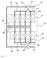
図2は1つのシリンダバンクの排気システムの立体図を示す。前記排気システムは、排気マニホールド15、16に結合されるシリンダ1〜3、5〜7に共通の第1の排気マニホールド25と、排気マニホールド25に一体化される排ガスターボチャージャ17、18用のハウジング26を有する。さらに、排気システムは、シリンダ4、8用の第2の排気マニホールド27と、排気マニホールド15、16への接続用のT状連結部28とを有する。図示された例示的実施形態において、第2の排気マニホールド27及びT状連結部28は一体型構造である。尚、代案として、異なる着脱可能な構成としたり、異なる固定連結部が第2のマニホールド27と連結部28との間に提供されても良い。
FIG. 2 shows a three-dimensional view of the exhaust system of one cylinder bank. The exhaust system includes a
2つのマニホールド25、27の相互の、及び内燃機関10と触媒コンバータ(図示せず)への連結は、同じようにフランジ連結を介して行われるのが好ましい。この目的で、第1のフランジ29は、ハウジング26の下流の第1のマニホールド25に形成され、対応する第2のフランジ30はT状連結部28に形成される。さらに、T状連結部28は、触媒コンバータ(図示せず)又は排気システムへの連結用の追加のフランジ31を下流端部に有する。最後に、第1及び第2の排気マニホールド25、27は、フランジ連結部を介して内燃機関10のシリンダバンク11、12に固定される。
The connection of the two
ひとつのシリンダバンク11、12に、それぞれ2つの独立した排気マニホールド25、27を使用することは、その配置構造が応力破壊にあまり左右されないという利点がある。
The use of two
図示した実施形態において、本発明は、8シリンダ1〜8を有するV型形式の内燃機関10を使用して説明されたが、異なる構造や、シリンダバンク11、12当りのシリンダ数が異なる内燃機関10でも同様に使用できる。どのシリンダ1〜8が独立排気ガスライン23、24を介して排気マニホールド13、14に連結されるかも、特に、それぞれの点火順序によって決まる。図示された実施形態において、各シリンダバンク11、12の最後の2つのシリンダ4、8は、ガス充填効率に関し重要であるので、独立した排気ガスライン23、24を対応づけるようにした。この場合、その結果は、特に簡単な構造となる。しかしながら、必要ならば、いかなる他のシリンダ1〜8も独立した排気ガスライン23、24を割り当てることができる。
In the illustrated embodiment, the present invention has been described using a V-type
図示していないが、他の実施形態として、シリンダバンク11、12当り2つ又はそれ以上のシリンダ1〜8からの排気ガスを、排ガスターボチャージャ17、18を迂回させるようにでき、その場合、それらのシリンダごとに独立した多数の排気ガスラインを設けても良いし、それらのシリンダ1〜8からの排気を結合した排気ガスラインを設けるようにしても良い。
Although not shown, as another embodiment, exhaust gas from two or more cylinders 1-8 per
Claims (6)
燃焼用空気を内燃機関(10)に送る吸気ライン(13、14)と、
排気ガスをシリンダバンク(11、12)の複数のシリンダ(1〜8)から排出する排気マニホールド(15、16)と、
排ガスターボチャージャ(17、18)を有し、そのタービン(19、20)が前記排気マニホールド(15、16)に設けられ、そのコンプレッサ(21、22)が前記吸気ライン(13、14)に設けられ、前記シリンダバンク(11、12)の少なくとも1つのシリンダ(4、8)が、該排ガスターボチャージャ(17、18)の該タービン(19、20)の下流側で前記排気マニホールド(15、16)と結合される独立した排気ガスライン(23、24)を有する過給式内燃機関(10)において、
90°点火オフセットが第1のシリンダ(1;2;3、5;6;7)と第2のシリンダ(4、8)との間に提供され、前記2つのシリンダの一方(4、8)が前記独立排気ガスライン(23、24)に連結され、前記2つのシリンダの他方(1;2;3、5;6;7)が前記排気マニホールド(15、16)に連結されることを特徴とする過給式内燃機関(10)。 A plurality of cylinders (1-8) arranged in at least one cylinder bank (11, 12);
An intake line (13, 14) for sending combustion air to the internal combustion engine (10);
Exhaust manifolds (15, 16) for discharging exhaust gas from the plurality of cylinders (1-8) of the cylinder bank (11, 12);
It has an exhaust gas turbocharger (17, 18), its turbine (19, 20) is provided in the exhaust manifold (15, 16), and its compressor (21, 22) is provided in the intake line (13, 14). And at least one cylinder (4, 8) of the cylinder bank (11, 12) is connected to the exhaust manifold (15, 16) downstream of the turbine (19, 20) of the exhaust gas turbocharger (17, 18). In a supercharged internal combustion engine (10) having independent exhaust gas lines (23, 24) coupled to
A 90 ° ignition offset is provided between the first cylinder (1; 2; 3,5; 6; 7) and the second cylinder (4,8), one of the two cylinders (4,8) Is connected to the independent exhaust gas line (23, 24), and the other of the two cylinders (1; 2; 3, 5; 6; 7) is connected to the exhaust manifold (15, 16). A supercharged internal combustion engine (10).
0 2. Cylinder bank (11, 12) arranged in a V-shape is connected to an exhaust manifold (15, 16) and at least one independent exhaust gas line (23, 24). Supercharged internal combustion engine.
0
Applications Claiming Priority (2)
| Application Number | Priority Date | Filing Date | Title |
|---|---|---|---|
| DE102004054726A DE102004054726A1 (en) | 2004-11-12 | 2004-11-12 | Charged internal combustion engine |
| PCT/EP2005/011914 WO2006050896A1 (en) | 2004-11-12 | 2005-11-08 | Supercharged internal combustion engine |
Publications (2)
| Publication Number | Publication Date |
|---|---|
| JP2008519931A true JP2008519931A (en) | 2008-06-12 |
| JP2008519931A5 JP2008519931A5 (en) | 2011-04-14 |
Family
ID=35539288
Family Applications (1)
| Application Number | Title | Priority Date | Filing Date |
|---|---|---|---|
| JP2007540555A Pending JP2008519931A (en) | 2004-11-12 | 2005-11-08 | Supercharged internal combustion engine |
Country Status (4)
| Country | Link |
|---|---|
| US (1) | US7610758B2 (en) |
| JP (1) | JP2008519931A (en) |
| DE (1) | DE102004054726A1 (en) |
| WO (1) | WO2006050896A1 (en) |
Families Citing this family (4)
| Publication number | Priority date | Publication date | Assignee | Title |
|---|---|---|---|---|
| DE102007006699A1 (en) | 2007-02-10 | 2008-08-14 | Bayerische Motoren Werke Aktiengesellschaft | Exhaust system for an internal combustion engine |
| DE102008047448B4 (en) | 2008-09-16 | 2020-09-24 | Bayerische Motoren Werke Aktiengesellschaft | Exhaust gas turbocharger |
| DE102009030015A1 (en) | 2009-06-23 | 2010-12-30 | Bayerische Motoren Werke Aktiengesellschaft | Multipart exhaust manifold for connecting exhaust outlets of cylinder head of internal combustion engine with exhaust gas turbine housing, has exhaust manifold part connected with exhaust gas outlets |
| DE102009057645A1 (en) * | 2009-12-09 | 2011-06-16 | Bayerische Motoren Werke Aktiengesellschaft | Exhaust manifold for an internal combustion engine |
Citations (7)
| Publication number | Priority date | Publication date | Assignee | Title |
|---|---|---|---|---|
| JPS61207826A (en) * | 1985-03-12 | 1986-09-16 | Mazda Motor Corp | Engine equipped with exhaust turbosupercharger |
| JPS62189328A (en) * | 1986-02-14 | 1987-08-19 | Mazda Motor Corp | Supercharger of engine |
| JPH0571356A (en) * | 1991-09-04 | 1993-03-23 | Isuzu Ceramics Kenkyusho:Kk | Control device for exhaust gas flow to turbo-charger |
| JPH05141256A (en) * | 1991-11-21 | 1993-06-08 | Isuzu Motors Ltd | Control device for turbocharger |
| EP1083318A2 (en) * | 1999-09-10 | 2001-03-14 | Ford Global Technologies, Inc. | Engine with direct turbo compounding |
| JP2003184532A (en) * | 2001-11-07 | 2003-07-03 | Dr Ing H C F Porsche Ag | Crankcase ventilation system for internal combustion engine with exhaust gas turbocharging |
| JP2005291045A (en) * | 2004-03-31 | 2005-10-20 | Mazda Motor Corp | Multi-cylinder engine with turbo type supercharger |
Family Cites Families (19)
| Publication number | Priority date | Publication date | Assignee | Title |
|---|---|---|---|---|
| DE2034312C3 (en) * | 1970-07-10 | 1974-01-10 | Aktiengesellschaft Kuehnle, Kopp & Kausch, 6710 Frankenthal | Exhaust system for six-cylinder in-line internal combustion engine with exhaust gas turbocharger |
| US3768248A (en) * | 1971-12-27 | 1973-10-30 | Caterpillar Tractor Co | Exhaust manifolding |
| IT1149783B (en) * | 1982-02-26 | 1986-12-10 | Alfa Romeo Auto Spa | MODULAR TYPE MULTI-CYLINDER ENGINE, WITH SUPERCHARGING |
| DE3312093A1 (en) * | 1983-04-02 | 1984-10-04 | Volkswagenwerk Ag, 3180 Wolfsburg | Internal combustion engine equipped with an exhaust turbocharger |
| US4514986A (en) * | 1983-07-18 | 1985-05-07 | Benson Steven R | Double-chambered exhaust manifold |
| JPS6026125A (en) * | 1983-07-21 | 1985-02-09 | Nissan Motor Co Ltd | Supercharged internal-combustion engine |
| JPS6141034A (en) * | 1984-08-02 | 1986-02-27 | Toyota Motor Corp | V-type 8-cylinder 4-cycle internal-combustion engine |
| JPH0791993B2 (en) * | 1986-08-26 | 1995-10-09 | マツダ株式会社 | Engine exhaust system |
| DE3824346A1 (en) | 1988-07-19 | 1989-12-07 | Daimler Benz Ag | Internal combustion engine with two cylinder banks |
| DE19625990A1 (en) * | 1996-06-28 | 1998-01-02 | Daimler Benz Ag | Arrangement of exhaust gas turbocharger and exhaust manifold on an internal combustion engine |
| US5692375A (en) * | 1996-12-11 | 1997-12-02 | Ford Global Technologies, Inc. | Bifurcated exhaust manifold for a V-type engine |
| SE508090C2 (en) * | 1996-12-17 | 1998-08-24 | Volvo Ab | Turbocharged internal combustion engine |
| DE19737968C1 (en) * | 1997-08-30 | 1998-12-10 | Daimler Benz Ag | Fuel injector for multiple cylinder internal combustion engine |
| SE510714C2 (en) * | 1997-10-09 | 1999-06-14 | Volvo Ab | Turbocharged internal combustion engine |
| DE19831251C2 (en) * | 1998-07-11 | 2000-04-27 | Daimler Chrysler Ag | Rechargeable internal combustion engine with cylinder deactivation |
| AT5141U1 (en) * | 2000-08-24 | 2002-03-25 | Avl List Gmbh | FOUR-STROKE OUTBOARD INTERNAL COMBUSTION ENGINE FOR DRIVING A WATER VEHICLE |
| DE10217225B4 (en) | 2002-04-18 | 2008-10-23 | Caterpillar Motoren Gmbh & Co. Kg | Charged multi-cylinder internal combustion engine |
| FR2869352B1 (en) * | 2004-04-22 | 2008-07-18 | Renault Sas | EXHAUST MANIFOLD FOR INTERNAL COMBUSTION ENGINE |
| US7979193B2 (en) * | 2007-10-15 | 2011-07-12 | Harbert Richard H | Even fire 90°V12 IC engines, fueling and firing sequence controllers, and methods of operation by PS/P technology and IFR compensation by fuel feed control |
-
2004
- 2004-11-12 DE DE102004054726A patent/DE102004054726A1/en not_active Withdrawn
-
2005
- 2005-11-08 WO PCT/EP2005/011914 patent/WO2006050896A1/en active Application Filing
- 2005-11-08 JP JP2007540555A patent/JP2008519931A/en active Pending
-
2007
- 2007-05-09 US US11/801,413 patent/US7610758B2/en not_active Expired - Fee Related
Patent Citations (7)
| Publication number | Priority date | Publication date | Assignee | Title |
|---|---|---|---|---|
| JPS61207826A (en) * | 1985-03-12 | 1986-09-16 | Mazda Motor Corp | Engine equipped with exhaust turbosupercharger |
| JPS62189328A (en) * | 1986-02-14 | 1987-08-19 | Mazda Motor Corp | Supercharger of engine |
| JPH0571356A (en) * | 1991-09-04 | 1993-03-23 | Isuzu Ceramics Kenkyusho:Kk | Control device for exhaust gas flow to turbo-charger |
| JPH05141256A (en) * | 1991-11-21 | 1993-06-08 | Isuzu Motors Ltd | Control device for turbocharger |
| EP1083318A2 (en) * | 1999-09-10 | 2001-03-14 | Ford Global Technologies, Inc. | Engine with direct turbo compounding |
| JP2003184532A (en) * | 2001-11-07 | 2003-07-03 | Dr Ing H C F Porsche Ag | Crankcase ventilation system for internal combustion engine with exhaust gas turbocharging |
| JP2005291045A (en) * | 2004-03-31 | 2005-10-20 | Mazda Motor Corp | Multi-cylinder engine with turbo type supercharger |
Also Published As
| Publication number | Publication date |
|---|---|
| US20070283938A1 (en) | 2007-12-13 |
| WO2006050896A1 (en) | 2006-05-18 |
| US7610758B2 (en) | 2009-11-03 |
| DE102004054726A1 (en) | 2006-06-08 |
Similar Documents
| Publication | Publication Date | Title |
|---|---|---|
| US8220264B2 (en) | Integrated inboard exhaust manifolds for V-type engines | |
| US6158218A (en) | Superchargeable internal combustion engine with cylinder cut-off | |
| JP5259822B2 (en) | Exhaust turbocharger for automobile internal combustion engine | |
| US8991177B2 (en) | Internal combustion engine | |
| US8146359B2 (en) | Dual inlet turbocharger system for internal combustion engine | |
| JPS645051Y2 (en) | ||
| JP2009250232A (en) | Integrated type engine of exhaust manifold and cylinder head | |
| KR20120053517A (en) | Exhaust-gas supply device of a turbine wheel of an exhaust-gas turbocharger | |
| US7757489B2 (en) | Engine configuration including an internal combustion engine | |
| US20070261680A1 (en) | Inlet air heater system | |
| CN102889111A (en) | Secondary air injection system and method | |
| CN101326068A (en) | Internal combustion engine with a turbocharger | |
| WO2004101971A1 (en) | Turbo compressor system for internal combustion engine comprising two serially placed turbo units with their rotation axes essentially concentric | |
| US7950229B2 (en) | Exhaust system for an internal combustion engine | |
| KR20110011608U (en) | Internal combustion engine | |
| JP2008519931A (en) | Supercharged internal combustion engine | |
| US6185938B1 (en) | Turbo-charged internal combustion engine | |
| US20030159443A1 (en) | Two-stage supercharging on a V-engine | |
| CN110431293B (en) | Internal combustion engine | |
| EP1797282A1 (en) | Turbo charger unit comprising double entry turbine | |
| JP2010106810A (en) | V-type internal combustion engine | |
| JP2008519931A5 (en) | ||
| JP2007032476A (en) | Internal combustion engine control device | |
| CN112689705A (en) | Method for operating an internal combustion engine | |
| JP4499961B2 (en) | Multi-cylinder supercharged engine |
Legal Events
| Date | Code | Title | Description |
|---|---|---|---|
| A621 | Written request for application examination |
Free format text: JAPANESE INTERMEDIATE CODE: A621 Effective date: 20081003 |
|
| A131 | Notification of reasons for refusal |
Free format text: JAPANESE INTERMEDIATE CODE: A131 Effective date: 20101117 |
|
| A524 | Written submission of copy of amendment under section 19 (pct) |
Free format text: JAPANESE INTERMEDIATE CODE: A524 Effective date: 20110217 |
|
| RD03 | Notification of appointment of power of attorney |
Free format text: JAPANESE INTERMEDIATE CODE: A7423 Effective date: 20110217 |
|
| A131 | Notification of reasons for refusal |
Free format text: JAPANESE INTERMEDIATE CODE: A131 Effective date: 20110906 |
|
| A02 | Decision of refusal |
Free format text: JAPANESE INTERMEDIATE CODE: A02 Effective date: 20120327 |