JP2008519638A - Steam iron with two flat resistance heating elements for heating the bottom - Google Patents
Steam iron with two flat resistance heating elements for heating the bottom Download PDFInfo
- Publication number
- JP2008519638A JP2008519638A JP2007540789A JP2007540789A JP2008519638A JP 2008519638 A JP2008519638 A JP 2008519638A JP 2007540789 A JP2007540789 A JP 2007540789A JP 2007540789 A JP2007540789 A JP 2007540789A JP 2008519638 A JP2008519638 A JP 2008519638A
- Authority
- JP
- Japan
- Prior art keywords
- heating element
- steam generator
- steam
- steam iron
- power
- Prior art date
- Legal status (The legal status is an assumption and is not a legal conclusion. Google has not performed a legal analysis and makes no representation as to the accuracy of the status listed.)
- Granted
Links
Images


Classifications
-
- D—TEXTILES; PAPER
- D06—TREATMENT OF TEXTILES OR THE LIKE; LAUNDERING; FLEXIBLE MATERIALS NOT OTHERWISE PROVIDED FOR
- D06F—LAUNDERING, DRYING, IRONING, PRESSING OR FOLDING TEXTILE ARTICLES
- D06F75/00—Hand irons
- D06F75/08—Hand irons internally heated by electricity
- D06F75/26—Temperature control or indicating arrangements
-
- D—TEXTILES; PAPER
- D06—TREATMENT OF TEXTILES OR THE LIKE; LAUNDERING; FLEXIBLE MATERIALS NOT OTHERWISE PROVIDED FOR
- D06F—LAUNDERING, DRYING, IRONING, PRESSING OR FOLDING TEXTILE ARTICLES
- D06F75/00—Hand irons
- D06F75/08—Hand irons internally heated by electricity
- D06F75/24—Arrangements of the heating means within the iron; Arrangements for distributing, conducting or storing the heat
Abstract
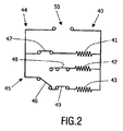
底部及びスチーム発生器を有するスチームアイロンは、2つの並列ループ(44,45)を有するヒーター回路を有し、主底部加熱要素(41)は第1ループ(44)に備えられ、補助底部加熱要素(42)及びスチーム発生器加熱要素(43)は第2ループ(45)に備えられている。第2ループ(45)においては、選択スイッチ(46)が、電源(50)に補助底部加熱要素(42)か又はスチーム発生器加熱要素(43)のどちらかを接続するために備えられている。選択スイッチ(46)の位置はヒーター回路(40)の動作状態を決定する。可能な一動作状態においては、底部加熱要素(41,42)両方が電源(50)に接続されている。この動作状態においては、利用可能な電力全てが底部を加熱するために用いられるため、底部は高速で加熱される。A steam iron having a bottom and a steam generator has a heater circuit having two parallel loops (44, 45), a main bottom heating element (41) is provided in the first loop (44), and an auxiliary bottom heating element. (42) and a steam generator heating element (43) are provided in the second loop (45). In the second loop (45), a selection switch (46) is provided to connect either the auxiliary bottom heating element (42) or the steam generator heating element (43) to the power source (50). . The position of the selection switch (46) determines the operating state of the heater circuit (40). In one possible operating state, both bottom heating elements (41, 42) are connected to a power source (50). In this operating state, the bottom is heated at high speed since all available power is used to heat the bottom.
Description
本発明は、スチームアイロンであって、アイロン掛けされるアイテムに接触するための接触表面を有する底部と、底部及びスチーム発生器を加熱するための加熱要素とを有する、スチームアイロンに関する。 The present invention relates to a steam iron having a bottom having a contact surface for contacting the item to be ironed and a heating element for heating the bottom and the steam generator.
そのようなスチームアイロンは既知であり、家庭の状況にしばしば適用される電気装置である。典型的には、そのような状況においては、好適な最大電力使用量は2300Wである。電力の使用を調整する必要性の観点から、適切な規則を構築するタスクを有する国際電気技術委員会(IEC)が設立された。例えば、電磁環境両立性(EMC)の分野で、IEC規則は、家庭用電気製品が非常に頻繁にオン/オフを切り換えられることが可能でないことを定めている。これは、スチームアイロンが底部及びスチーム発生器を加熱するための加熱要素を有し、そのスチーム発生器は、ユーザの要求に対して底部及びスチーム発生器の状態を適合させる連続処理の結果として、頻繁に活性化及び非活性化されるために、スチームアイロンに対する興味の重要な点となっている。IEC規則を破ることなく、スチームアイロンの性能を改善するように、十分な電力供給を利用する必要性が存在する。特に、スチームレート、即ち、単位時間当たりに供給さえるスチーム量を増加させる要請、及び底部の加熱時間を短縮するための要請が存在する。 Such steam irons are known and are electrical devices that are often applied to the home situation. Typically, in such situations, the preferred maximum power usage is 2300W. In view of the need to coordinate the use of electricity, the International Electrotechnical Commission (IEC) was established with the task of developing appropriate rules. For example, in the field of electromagnetic compatibility (EMC), IEC regulations stipulate that home appliances cannot be switched on and off very frequently. This is because the steam iron has a heating element for heating the bottom and the steam generator, which steam generator, as a result of continuous processing to adapt the bottom and steam generator conditions to the user's requirements, Frequent activation and deactivation has become an important point of interest for steam irons. There is a need to utilize a sufficient power supply so as to improve the performance of the steam iron without breaking IEC regulations. In particular, there is a request to increase the steam rate, that is, the amount of steam supplied per unit time, and a request to shorten the bottom heating time.
欧州特許第1384808号明細書において、水を有し且つスチームにするように水を加熱するためのボイラーと、アイロン掛けプレートと、スチームアイロンを機能するようにするために利用できる電力全てをバランスよい方式で配分し、最大に利用するようにデザインされた電気装置とが開示されている。このために、その電子装置は、アイロン掛けプレートと直接、接するように備えられた1つの電気抵抗と、ボイラーの内部に備えられた2つの電気抵抗とを有する。更に、その電気装置はスイッチを有する。それらの抵抗及びスイッチの構成は、スイッチの第1動作条件においては、ボイラーの抵抗の1つのみがフィーダに接続され、スイッチの第2動作条件においては、3つの抵抗全てがフィーダに接続され、ボイラーの抵抗は直列に接続され、アイロン掛けプレートの抵抗はボイラーの抵抗に対して並列に接続されている。 In European Patent No. 1384808, there is a balance between the boiler for heating the water to have water and steam, the ironing plate, and all the power available to make the steam iron work. An electrical device is disclosed that is designed to be distributed in a manner and to be utilized to the maximum. For this purpose, the electronic device has one electrical resistance provided in direct contact with the ironing plate and two electrical resistances provided inside the boiler. Furthermore, the electrical device has a switch. These resistors and switch configurations are such that, in the first operating condition of the switch, only one of the boiler resistances is connected to the feeder, and in the second operating condition of the switch, all three resistors are connected to the feeder, The resistance of the boiler is connected in series, and the resistance of the ironing plate is connected in parallel to the resistance of the boiler.
既知のスチームアイロンの動作中に、第1抵抗と呼ばれる、ボイラーの抵抗の1つは常にフィーダに接続されている。スイッチの第1動作状態においては、第1抵抗はフィーダに接続された抵抗のみであり、全ての利用可能な電力はボイラーを加熱するために用いられる。スイッチの第2動作状態においては、3つの抵抗全てがフィーダに接続され、利用可能な電力の一部はボイラーを加熱するために用いられ、利用可能な電力の他の部分はアイロン掛けプレートを加熱するために用いられる。 During operation of the known steam iron, one of the boiler resistances, called the first resistance, is always connected to the feeder. In the first operating state of the switch, the first resistor is only the resistor connected to the feeder and all available power is used to heat the boiler. In the second operating state of the switch, all three resistors are connected to the feeder, part of the available power is used to heat the boiler, and the other part of the available power heats the ironing plate Used to do.
スチームアイロンの分野においては、底部及びスチーム発生器を加熱するために、所謂、扁平な抵抗加熱要素を適用することが好ましい。完全化のために、扁平な抵抗加熱要素は、プリンティング又は他の適切な技術により、表面における薄い層として堆積される加熱要素であることに留意する必要がある。電流の影響下で、その扁平な抵抗加熱要素は、熱を発生することができる。例えば、扁平な抵抗加熱要素は、電気導電性粒子が埋め込まれた合成樹脂の層により構成されている。扁平な抵抗加熱要素が、金属等の電気導電性材料を有する表面に備えられているとき、電気絶縁層が、回路の短絡を回避するように、その表面と加熱要素との間に備えられる必要がある。扁平な抵抗加熱要素は平面的な表面に備えられているが、曲面的な表面にこの種類の加熱要素を備えることがまた、可能である。 In the field of steam irons, it is preferable to apply so-called flat resistance heating elements to heat the bottom and the steam generator. It should be noted that for completeness, a flat resistive heating element is a heating element that is deposited as a thin layer on the surface by printing or other suitable technique. Under the influence of current, the flat resistance heating element can generate heat. For example, a flat resistance heating element is constituted by a layer of synthetic resin in which electrically conductive particles are embedded. When a flat resistance heating element is provided on a surface having an electrically conductive material such as metal, an electrical insulation layer must be provided between the surface and the heating element so as to avoid short circuits There is. Although the flat resistance heating element is provided on a planar surface, it is also possible to provide this type of heating element on a curved surface.
扁平な抵抗加熱要素の重要な有利点は、それらの要素が、他の種類の加熱要素と比べて、非常にコンパクト且つ軽量であることである。しかしながら、それらの加熱要素は、特に高温において、比較的壊れ易いために、それらの抵抗加熱要素の適用には制約がある。それ故、扁平な抵抗加熱要素の高信頼性の性能を得るためには、それらの加熱要素を低電力密度且つ低温度で機能させるようにすることが好ましい。スチームアイロンにおいては、底部は、200℃以上の温度に、例えば、210℃にされることが可能であり、それ故、低温にすることが可能でない。それ故、スチームアイロンに扁平な抵抗加熱要素を適用することができるように、特に、スチームアイロンの底部を加熱するために用いられる扁平な抵抗加熱要素のために、できるだけ小さい電力密度を保つための手段についての要請が存在している。 An important advantage of flat resistive heating elements is that they are very compact and lightweight compared to other types of heating elements. However, the application of these resistive heating elements is limited because they are relatively fragile, especially at high temperatures. Therefore, in order to obtain the highly reliable performance of the flat resistance heating elements, it is preferable that the heating elements function at a low power density and a low temperature. In a steam iron, the bottom can be brought to a temperature of 200 ° C. or higher, for example 210 ° C., and therefore cannot be lowered. Therefore, in order to be able to apply a flat resistance heating element to the steam iron, especially for the flat resistance heating element used to heat the bottom of the steam iron, to keep the power density as small as possible There is a request for means.
底部の加熱時間の減少及びスチーム化速度の増加についての非常なる要請に適合するように、底部を加熱するために利用可能な電力全てを用いることが可能であるスチームアイロンについての要請が存在している。
本発明の目的は、扁平な抵抗加熱要素を適用する可能性を許容するスチームアイロンを提供することである。 The object of the present invention is to provide a steam iron which allows the possibility of applying a flat resistance heating element.
その目的は、主加熱要素及び補助加熱要素であって、底部に関連付けられ、電力を受け入れるときに、底部を加熱することができ、電力を受け入れるときに、スチーム発生器と関連する加熱要素は、スチーム発生器を加熱することができる、主加熱要素及び補助加熱要素と、電力を供給するために電源に底部に関連するスチーム発生器又は補助加熱要素と関連する加熱要素に接続されるスイッチング手段と、有するスチームアイロンにより達成される。 Its purpose is a main heating element and an auxiliary heating element, which is associated with the bottom and can heat the bottom when receiving power, and when receiving power, the heating element associated with the steam generator is A main heating element and an auxiliary heating element capable of heating the steam generator; and switching means connected to the heating element associated with the steam generator or auxiliary heating element associated with the bottom to supply power to the power supply; This is achieved by having a steam iron.
本発明にしたがって、スチームアイロンは少なくとも3つの加熱要素を有し、少なくとも2つの要素は底部に関連していて、少なくとも1つの加熱要素はスチーム発生器に関連している。底部と関連する2つの加熱要素の一は主加熱要素と呼ばれ、それらの2つの加熱要素の他は補助加熱要素と呼ばれる。スチームアイロンの動作中、スイッチング手段の位置は、どの加熱要素が用いられるかを判定する。スイッチング手段の第1位置においては、底部に関連する主加熱要素及びスチーム発生器に関連する加熱要素の両方が用いられ、スイッチング手段の第2位置においては、底部に関連する主加熱要素及び底部に関連する補助加熱要素の両方が用いられる。それ故、底部に関連する一の加熱要素が独占的に加熱される状態は起こらない。したがって、底部に関連する加熱要素のための電力密度は、全ての環境下で制限され、それ故、それらの加熱要素が最大電力を取り込むことができる必要はない。それ故、本発明にしたがったスチームアイロンにおいては、加熱要素が破壊するリスクを伴うことなく、扁平な抵抗加熱要素を提供することが可能である。 In accordance with the present invention, the steam iron has at least three heating elements, at least two elements are associated with the bottom and at least one heating element is associated with the steam generator. One of the two heating elements associated with the bottom is called the main heating element and the other of the two heating elements is called the auxiliary heating element. During operation of the steam iron, the position of the switching means determines which heating element is used. In the first position of the switching means, both the main heating element associated with the bottom and the heating element associated with the steam generator are used, and in the second position of the switching means, the main heating element and the bottom associated with the bottom. Both associated auxiliary heating elements are used. Therefore, the situation in which one heating element associated with the bottom is heated exclusively does not occur. Thus, the power density for the heating elements associated with the bottom is limited under all circumstances and therefore it is not necessary for those heating elements to be able to capture maximum power. Therefore, in the steam iron according to the present invention, it is possible to provide a flat resistance heating element without the risk of the heating element breaking.
本発明にしたがったスチームアイロンにおいては、スイッチング手段の位置に拘わらず、利用可能な電力が完全に適用されることが可能であり、それ故、スチームアイロンの性能は最適化される。このような可能性を実現するように、底部に関連する補助加熱要素及びスチーム発生器に関連する加熱要素の両方が底部に関連する主加熱要素に対して並列に備えられることは好ましい。そのような場合、全電力は、スイッチング手段の第1位置においては、底部に関連する主加熱要素及びスチーム発生器に関連する加熱要素の間で分配され、スイッチング手段の第2位置においては、全電力は、底部に関連する主加熱要素及び底部に関連する補助加熱要素の間で分配される。 In a steam iron according to the invention, the available power can be fully applied regardless of the position of the switching means, and therefore the performance of the steam iron is optimized. In order to realize this possibility, it is preferred that both the auxiliary heating element associated with the bottom and the heating element associated with the steam generator are provided in parallel with the main heating element associated with the bottom. In such a case, the total power is distributed between the main heating element associated with the bottom and the heating element associated with the steam generator in the first position of the switching means and in the second position of the switching means. Power is distributed between the main heating element associated with the bottom and the auxiliary heating element associated with the bottom.
スイッチング手段の第1位置においては、全電力は、底部を加熱する目的及びスチーム発生器を加熱する目的の両方のために用いられ、スイッチング手段の第2位置においては、全電力は、底部を加熱する目的のみのために用いられる。スチームアイロンの実際的な実施形態においては、スチーム発生器の重量は底部の重量より軽く、スチーム発生器に関連する加熱要素の電気抵抗は、底部に関連する主加熱要素の電気抵抗より小さい。そのような実施形態においては、開始時間、即ち、ユーザにより活性化された後に、スチームアイロンを使用する準備ができるのに要する時間が比較的短いことが可能である。まさに開始する時点で、スイッチング手段は第1位置にあり、全電力は、底部及びスチーム発生器の両方を加熱するように用いられる。スチーム発生器の重量は底部の重量より軽く、スチーム発生器に供給される全電力の割合は、底部に供給される全電力の割合より大きいので、スチーム発生器に関連する加熱要素の電気抵抗が底部に関連する主加熱要素の電気抵抗より小さいということのために、スチーム発生器は、早い段階で所定の温度に到達し、底部は、尚も、加熱過程にある。スチーム発生器の温度が所定レベルに達するとすぐに、スイッチング手段の位置は変えられ、全電力は、底部に関連する2つの加熱要素を介して、底部に供給される。その結果、底部は最大電力で加熱され、比較的速く、所定温度に達する。このようにして、比較的短い開始時間が実現される。 In the first position of the switching means, the total power is used for both the purpose of heating the bottom and for the purpose of heating the steam generator, and in the second position of the switching means, the total power heats the bottom. Used only for the purpose of. In a practical embodiment of the steam iron, the weight of the steam generator is lighter than the weight of the bottom, and the electrical resistance of the heating element associated with the steam generator is less than the electrical resistance of the main heating element associated with the bottom. In such embodiments, the start time, i.e., the time required to be ready to use the steam iron after being activated by the user can be relatively short. At the very beginning, the switching means is in the first position and the full power is used to heat both the bottom and the steam generator. The weight of the steam generator is lighter than the weight of the bottom, and the proportion of the total power supplied to the steam generator is greater than the proportion of the total power supplied to the bottom, so the electrical resistance of the heating element associated with the steam generator is Due to being less than the electrical resistance of the main heating element associated with the bottom, the steam generator reaches a predetermined temperature at an early stage and the bottom is still in the heating process. As soon as the temperature of the steam generator reaches a predetermined level, the position of the switching means is changed and the total power is supplied to the bottom via two heating elements associated with the bottom. As a result, the bottom is heated at maximum power and reaches a predetermined temperature relatively quickly. In this way, a relatively short start time is realized.
本発明について、以下、図を参照して詳述する。それらの図においては、同様な構成要素には同じ参照番号が付けられている。 The present invention will be described in detail below with reference to the drawings. In those figures, similar components are given the same reference numerals.
図1は、本発明にしたがったスチームアイロン1を示している。スチームアイロン1の一部は、スチームアイロン1の内部に備えられている構成要素を示すために内部が見えるようにされている。スチームアイロン1は、アイロン掛けされるアイテムと接するための平面状接触面11を有する底部10を有する。底部10において、スチームを通すためのスチーム開口(図示せず)が備えられている。スチームを発生させて供給するために、スチームアイロン1はスチーム発生器20を有する。底部10及びスチーム発生器20は、例えば、アルミニウム合金から成ることが可能である。
FIG. 1 shows a steam iron 1 according to the invention. A portion of the steam iron 1 is made visible inside to show the components provided within the steam iron 1. The steam iron 1 has a
底部10及びスチーム発生器20の他に、スチームアイロン1は、底部10の上部に位置し、ユーザがスチームアイロンを持ち上げて、アイロン掛けされるべきアイテムにおいて底部10の接触面11を動かすことを可能にするようにハンドル31を有するハウジング30を有する。図示されている実施例においては、スチーム発生器20はハウジング内に収容されている。そのことは、スチーム発生器20がハウジング30の外側に備えられる代替の実施形態がまた、本発明の範囲内で可能であることを変えるものではない。そのような実施形態においては、スチームアイロン1は、好適には、スチーム発生器20から底部10におけるスチーム開口にスチームを導くためのスチームホースを有する。
In addition to the
スチームアイロン1の動作中に、底部10及びスチーム発生器20は加熱され、スチームアイロン1は、一方で、底部10の厚い接触面11とアイテムとの間の接触に基づいて、他方で、そのアイテムへのスチームの供給に基づいて、繊維アイテムの皺取りのために用いられるように適合される。底部10及びスチーム発生器20を加熱するために、加熱要素を有するヒーター回路40が備えられている。スチームアイロン1は、ヒーター回路40と電源(図1においては図示していない)との間の接続を与えるように、図1に一部のみが示されている電力ケーブル32を有する。
During operation of the steam iron 1, the bottom 10 and the
好適には、本発明にしたがって、加熱要素は、扁平な抵抗加熱要素を有する。本発明の重要な特徴にしたがって、2つの加熱要素が底部10に関連付けられ、1つの加熱要素はスチーム発生器20に関連付けられている。底部10に関連付けられている2つの加熱要素の一は主加熱要素41と呼ばれる。底部10に関連付けられている2つの加熱要素の他は補助加熱要素42と呼ばれる。スチーム発生器20に関連付けられている加熱要素ハスチーム発生器加熱要素43と呼ばれる。
Suitably, according to the invention, the heating element comprises a flat resistance heating element. In accordance with an important feature of the present invention, two heating elements are associated with the bottom 10 and one heating element is associated with the
本発明にしたがったスチームアイロン1の図示している実施形態においては、スチーム発生器20は、底部10に比べてかなり少ない重量を有する。例えば、スチーム発生器20の重量は250gである一方、底部10の重量は800gである。スチーム発生器20は何れの適切な形を有することが可能である。一実施形態にしたがって、スチーム発生器20は小片の金属を有し、その金属は、水の流れを通すことができるものである。この種類のスチーム発生器20は水を蓄えることはできず、スチームが必要ない時間の期間中、乾いたまま保たれる。スチームアイロン1の動作中、スチーム発生器20は、略一定温度、例えば、160℃に保たれ、それ故、スチーム発生器20に入る水はすぐに蒸発される。
In the illustrated embodiment of the steam iron 1 according to the invention, the
スチームアイロン1は、スチームがスチームアイロン1のユーザにより必要とされる場合に、スチーム発生器20に供給されるようになっている水を有する水タンク21を有する。ハウジング30の内側に位置付けられている水タンクと比べて、ハウジング30の外側に位置付けられている水タンク21は多くの有利点を有する。それらの有利点の1つは、スチームアイロン1のハウジング30の大きさに水タンク21の大きさを適合させる必要性がないことである。したがって、水タンク21は、しばしば、水を満たす必要がない程に非常に大きいことが可能である。水タンク21がスチームアイロン1のハウジング30の内側に位置付けられている場合、大きい水タンク21は水タンク21を満たす頻度は小さいことを意味するがまた、スチームアイロン21の体積は大きく且つ重量は重いことを意味する。本発明の範囲においては、ハウジング30の内側に位置付けられた水タンク21を有することは好適であるが、水タンク21がスチームアイロンのハウジング30の内側又は外側に位置付けられていることは関係ない。図1に示すスチームアイロン1の実施例においては、水タンク21は、適切なホース22を通ってスチーム発生器20に接続されている。
The steam iron 1 has a
ヒーター回路40の構成及びヒーター回路40の種々の動作状態については、図2乃至4に示されていて、下記のように説明することができる。図2乃至4においては、電源は、参照番号50で示されている。
The configuration of the
ヒーター回路40は2つの並列ループを有し、主加熱要素41は第1ループ44に備えられていて。補助加熱要素42及びスチーム発生器加熱要素43は第2ループに備えられている。この構成においては、補助加熱要素42及びスチーム発生器加熱要素43の両方は主加熱要素41に対して並列に備えられている。第2ループにおいては、選択スイッチ46が、電源50に補助加熱要素42を接続するためか又は、電源50にスチーム発生器加熱要素43を接続するためのどちらかで備えられている。それ故、選択スイッチ46は、電源50に補助加熱要素42及びスチーム発生器加熱要素43のどちらかの一のみを接続することができる。したがって、補助加熱要素42及びスチーム発生器加熱要素43が同時に電力供給されるようにされることは可能でない。下記においては、選択スイッチ46が電源50にスチーム発生器加熱要素43を接続し、電源50から補助加熱要素42の接続を切る選択スイッチ46の位置は第1位置と呼ばれる一方、選択スイッチ46が電源50に補助加熱要素42を接続し、電源50からのスチーム発生器加熱要素43接続を切る選択スイッチ46の位置は第2位置と呼ばれる。
The
選択スイッチ46の他に、ヒーター回路40は3つの接続スイッチを有し、第1接続スイッチ47は主加熱要素41と直列に備えられ、第2接続スイッチ48は補助加熱要素42と直列に備えられ、第3接続スイッチ49はスチーム発生器加熱要素43と直列に備えられている。好適には、3つの接続スイッチ47、48、49全ては、スチームアイロン1の関連構成要素の、即ち、第1接続スイッチ47及び第2接続スイッチ48の場合には底部10の、そして、第3接続スイッチ49の場合にはスチーム発生器20の温度に対して動作可能であり、接続スイッチ47、48、49は、関連構成要素の温度が所定の温度にある又はその所定の温度に比べて高いときには動作位置にあり、接続スイッチ47、48、49は、関連構成要素の温度が所定の温度に比べて低いときには閉状態の位置にある。実際の実施形態においては、接続スイッチ47、48、49はサーモスタットを有する。
In addition to the
閉状態の位置とも呼ばれる第1位置においては、第1接続スイッチ47は電源50に主加熱要素41を接続し、開状態の位置とも呼ばれる第2位置においては、第1接続スイッチ47は電源50から主加熱要素41の接続を切る。第2接続スイッチ48及び第3接続スイッチ49両方の位置はまた、閉状態又は開状態であることが可能である。開状態の位置においては、第2接続スイッチ48及び第3接続スイッチ49は、電源50から補助加熱要素42及びスチーム発生器加熱要素43のそれぞれの接続を切る。閉状態の位置においては、第2接続スイッチ48及び第3接続スイッチ49は、選択スイッチ46の位置に応じて、電源50に補助加熱要素42及びスチーム発生器加熱要素43のそれぞれを接続することができる。第2接続スイッチ48が閉状態の場合、補助加熱要素42と電源50との間の接続を有するように、選択スイッチ46が第2位置にあることが必要である。選択スイッチ46が第1位置にある場合、第2接続スイッチ48が閉状態にあるということにも拘わらず、そのような接続は存在しない。同様に、第3接続スイッチ49が閉状態の場合、スチーム発生器加熱要素43と電源50との間の接続を有するように、選択スイッチ46が第1位置にあることが必要である。選択スイッチ46が第2位置にある場合、第3接続スイッチ49が閉状態にあるということにも拘わらず、そのような接続は存在しない。
In the first position, also referred to as the closed position, the
ヒーター回路40、特に、選択スイッチ46を制御するために、スチームアイロン1はマイクロコントローラ(図示せず)を有する。マイクロコントローラは、接続スイッチ47、48、49の位置も制御するようにプログラムされることが可能である。そのような場合、温度検知手段(図示せず)が備えられ、その温度検知手段は、マイクロコントローラに底部10及びスチーム発生器20の実際の温度を表す信号を送信することができ、底部10及びスチーム発生器20の所定温度がマイクロコントローラに記憶されている。本発明の範囲においては、温度検知手段は自由に選択されることが可能である。例えば、接続スイッチ47、48、49は電子サーモスタットを有することが可能である。ヒーター回路40についての下の説明及びヒーター回路が制御される方式においては、接続スイッチ47、48、49は、マイクロコントローラにより制御される電子サーモスタットを有することが前提となっている。しかしながら、接続スイッチ47、48、49は、例えば、接続スイッチ47、48、49が機械式サーモスタット等を有する場合に、それらのそれぞれの位置を決定するようにマイクロコントローラからの入力を必要としないことがまた、可能である。そのような場合、マイクロコントローラの制御機能の一部は、サーモスタット自体により引き受けられる。更に、マイクロコントローラ以外に、単純な電気回路がまた、電子サーモスタットを介して底部10及びスチーム発生器20の温度を制御するために適用されることができる。
In order to control the
ヒーター回路40は、ユーザによりスチームアイロン1に課せられた要求とスチームアイロン1の構成要素、特に、底部10及びスチーム発生器20の実際の状態との間の進行中の比較に基づいて制御される。差が求められる場合、マイクロコントローラは、差を減少させ、スチームアイロン1のそれら構成要素の実際の状態をできるだけユーザの要求を満たすようにするように、適切に、1つ又はそれ以上の接続スイッチ47、48、49の位置を調節することにより、1つ又はそれ以上の加熱要素41、42、43を活性化させるようにプログラムされている。
The
スチームアイロン1は、底部10の温度を設定する少なくとも一回の機会をユーザに与える。図1においては、回転可能制御輪33が示されている。スチームアイロン1のハウジング30に対する制御輪33の全ての位置は、底部10の要求された温度を表し、マイクロコントローラにおける設定を決定する。制御輪33は、しばしば、サーモスタットダイヤル又は温度ダイヤルと呼ばれ、アイロン掛けされるべき繊維の種類に底部10の温度をユーザが調節するための簡易ツールを有する。アイロンが有効な一部の最近の市場においては、温度ダイヤルは温度調節ボタンで置き換えられる。
The steam iron 1 gives the user at least one opportunity to set the temperature of the bottom 10. In FIG. 1, a
図5は、ヒーター回路40を制御する好適な方法を示すフローチャートである。第1段階は、底部10及びスチーム発生器20の両方の温度をチェックする段階を有する。この段階は、スチームアイロン1の動作中に継続して繰り返される。
FIG. 5 is a flowchart illustrating a preferred method for controlling the
スチーム発生器20の温度が所定温度、即ち、所望のスチーム化速度が得られる温度より低い場合、第3接続スイッチ49は閉状態の位置になり、選択スイッチ46は第1位置になり、それ故、スチーム発生器加熱要素43は電源50に接続される。同時に、底部10の温度が所定温度より低いように現れる場合、第1接続スイッチ47は閉状態の位置になり、それ故、主加熱要素41は電源50に接続される。底部10の温度が所定温度より低いために、第2接続スイッチ48も閉状態の位置になる。得られたヒーター回路40の構成について、図2に示している。
When the temperature of the
第2接続スイッチ48が閉状態の位置にあるということにも拘わらず、補助加熱要素42は、選択スイッチ46が第1位置にあるために、電源50から接続を切られる。選択スイッチ46が第1位置にあるとき、補助加熱要素42は、第2接続要素48の位置に拘わらず、電源50から接続を切られる。
Despite the fact that the
スチーム発生器20の温度のチェックが所定の温度に達したことを示すとすぐに、スチーム発生器加熱要素43をもはや、動作させる必要はなくなる。その場合、第3接続スイッチは開状態の位置になり、選択スイッチ46は第2位置になり、それ故、補助加熱要素42は電源に接続される。得られたヒーター回路40の構成を図3に示している。このヒーター回路40の構成においては、底部10は、主加熱要素41及び補助加熱要素42の両方により加熱される。
As soon as a check of the temperature of the
底部10の温度のチェックが所定温度に達したことを示すとすぐに、第1接続スイッチ47及び第2接続スイッチ48は開状態の位置になり、それ故、主加熱要素41及び補助加熱要素42は電源50から接続を切られる。スチーム発生器20の温度のチェックが、この温度は所定温度より低いことを示す場合、第3接続スイッチ49は閉状態の位置になり、選択スイッチ46は第1位置になり、それ故、スチーム発生器加熱要素43は電源50に接続される。得られたヒーター回路40の構成を図4に示している。しかしながら、スチーム発生器20の所定温度にも達したように現れる場合、第3接続スイッチ49は開状態の位置のまま保たれ、選択スイッチ46は第2位置のまま保たれる。そのような場合、全ての加熱要素41、42、43は、全ての接続スイッチ47、48、49が開状態の位置にあるために、電源50から接続を切られる。更に、選択スイッチ46の位置は、加熱要素41、42、43の状態に影響しないため、重要でない。
As soon as the temperature check of the bottom 10 indicates that the predetermined temperature has been reached, the
加熱要素41、42、43の何れも、電源50に接続されていず、選択スイッチ46が第2位置にある状態から開始する場合、ヒーター回路40を再び、活性化するための異なる可能性が存在する。
If none of the
第1の可能性にしたがって、底部10の温度は関連所定温度より低くなり、スチーム発生器20の温度は、関連所定温度より高いままであるか、それと等しくなる。その場合、第1接続スイッチ47及び第2接続スイッチ48の両方は閉状態の位置になる一方、選択スイッチ46は第2位置のまま保たれる。したがって、主加熱要素41及び補助加熱要素42の両方は電源50に接続される。第3接続スイッチ49は開状態の位置のまま保たれる。
According to the first possibility, the temperature of the bottom 10 will be lower than the associated predetermined temperature, and the temperature of the
第2の可能性にしたがって、スチーム発生器20の温度は関連所定温度より低くなり、底部10の温度は、関連所定温度より高いままであるか、それと等しくなる。その場合、第3接続スイッチ49のみが閉状態の位置になり、選択スイッチ46は第1位置になる。したがって、スチーム発生器加熱要素43は電源50に接続され、主加熱要素42及び補助加熱要素42は電源50から接続を切られたまま保たれる。
According to a second possibility, the temperature of the
第3の可能性にしたがって、底部10の温度は関連所定温度より低くなり、スチーム発生器20の温度も、関連所定温度より低くなる。その場合、全ての3つの接続スイッチ47、48、49は閉状態の位置になる。更に、選択スイッチ46は第1位置になる。このようにして、ヒーター回路40の構成が得られ、その構成においては、主加熱要素41及びスチーム発生器加熱要素43は電源50に接続され、補助加熱要素42は電源50から接続を切られている。補助加熱要素42は、スチーム発生器20の温度が所定値に達するまで、電源50から接続を切られたまま保たれ、第3接続スイッチ49は開状態の位置になる。
According to a third possibility, the temperature of the bottom 10 will be lower than the relevant predetermined temperature, and the temperature of the
一般に、スチーム発生器加熱要素43を活性化する必要性がないときに、補助加熱要素42のみが活性化される。スチーム発生器20を加熱するように、スチーム発生器20に電力を供給することが必要である限り、電源50により供給される電力は、底部10とスチーム発生器20との間で分配される。スチーム発生器20が適切な温度にある場合にのみ、電源50により供給される全電力が、主加熱要素41及び補助加熱要素42を介して底部10に供給される。それ故、マイクロコントローラにおいては、スチーム発生器加熱要素43は補助加熱要素42より優先的であり、それ故、補助加熱要素42は、スチーム発生器20が尚も加熱される必要がある状態では、決して活性化されない。このことは、スチーム発生器20の温度が所定温度より低い限り、選択スイッチ46は第1位置にあることと、スチーム発生器20を加熱する必要がないとき、換言すれば、スチーム発生器20の温度が所定温度にある又は所定温度より高いとき、選択スイッチ46のみが第2位置になることを意味している。
In general, only the
スチーム発生器20を加熱する処理が全電力で底部10を加熱する処理より優先的であるように、ヒーター回路40を制御される方式の重要な有利点は、底部10が要求された温度にない場合であっても、スチームアイロン1が常に、スチームを供給することができることである。日宇―ター回路40の制御方法は、常に、所定温度にスチーム発生器20を保つように支援するため、スチーム発生器20は、スチーム発生器20を通るように去れる水を常に、蒸発させることができる。したがって、不所望の状態、例えば、スチームアイロン1が、スチームを開放することが必要であるときに水の液滴を飛ばす状態は、回避される。
An important advantage of the manner in which the
本発明にしたがったヒーター回路40においては、底部10に関連する1つの加熱要素のみが、即ち、主加熱要素41及び補助加熱要素42が電力供給される状態は生じない。主加熱要素41は常に、補助加熱要素42か又はスチーム発生器加熱要素43のどちらかと共に、電力供給され、補助加熱要素42は常に、主加熱要素41と共に電力供給される。したがって、電源50により供給される電力は、主加熱要素41及び補助加熱要素42の何れにより、完全に取り込まれることはない。このことは、それらの加熱要素41、42が扁平な抵抗加熱要素を有する場合に、非常に有利である。底部10の温度が比較的高い、例えば、210℃であるということにも拘わらず、扁平な抵抗加熱要素の性能は、それらの加熱要素の電力密度は制限されているために、非常に高い信頼性を有する。スチーム発生器20に関連する加熱要素43に関しては、この加熱要素43の最大動作温度は低く、それ故、電源50により供給される全電力を取り込むようになっている場合にも、この加熱要素43がそのままの状態を保ち、問題はないことに留意する必要がある。
In the
上記のようなヒーター回路を有する、本発明にしたがったスチームアイロン1は、EMCに関するIEC規則に準拠している。これに関連して、主加熱要素41が、補助加熱要素42とスチーム発生器加熱要素43との間の切り換えがなされるときに、電源50に接続されたまま保たれるということは、重要な役割を果たす。
The steam iron 1 according to the present invention having the heater circuit as described above complies with IEC regulations regarding EMC. In this connection, it is important that the
好適な実施形態においては、スチーム発生器20は底部10より小さい重量を有する。例えば、スチーム発生器20の重量は250gである一方、底部10の重量は800gである。更に、好適な実施形態においては、スチーム発生器加熱要素43の抵抗は主加熱要素41の抵抗より低い。例えば、スチーム発生器加熱要素43の抵抗は35.3Ωである一方、主加熱要素41の抵抗は66.1Ωである。その結果、スチーム発生器加熱要素43及び主加熱要素41が同一の電源に並列に接続されるとき、主加熱要素41により取り込まれる電力は、スチーム発生器加熱要素43により取り込まれる電力より低い。好適には、補助加熱要素42の抵抗ハスチーム発生器加熱要素43の抵抗と同じである。
In the preferred embodiment, the
本発明にしたがったスチームアイロン1の重要な有利点は、上記段落で規定された好適な実施形態の開始状態が考慮されるときに、明らかになり、その実施形態においては、底部10及びスチーム発生器20の両方の最初の温度は略環境温度にある。この状態では、底部10及びスチーム発生器20の両方は、スチームアイロン1を動作状態にするように加熱される必要があることは明らかである。それ故、まさに開始する時点では、全ての接続スイッチ47、48、49は閉状態の位置にあり、選択スイッチ46は第1位置にあり、それ故、主加熱要素41及びスチーム発生器加熱要素43の両方は電源50に接続されている。スチーム発生器20の重量は底部10の重量より小さく、スチーム発生器加熱要素43により取り込まれる電力は主加熱要素41により取り込まれる電力より大きい場合、スチーム発生器20は底部10よりかなり速く加熱される。例えば、電源50により供給される全電力は2300Wであり、そのうちの800Wは主加熱要素41により取り込まれ、そのうちの1500Wはスチーム発生器加熱要素43により取り込まれる。その場合、加熱要素41、42、43は扁平な抵抗加熱要素を有することを更に前提にすると、スチーム発生器20は、約20.6秒で所定の温度160℃に達する。そのとき、底部10は、尚も加熱処理中にある。スチーム発生器20が所定温度に達した時点から、選択スイッチ46は第2位置にあって、スチーム発生器加熱要素43は電源50から接続を切られていて、補助加熱要素42は電源50に接続されているため、底部19の加熱処理は高速で行われる。その時点で、電源50により供給される全電力は、底部10を加熱するために独占的に用いられる。その結果、底部10は、約41.1秒で所定の開始温度110℃に達することができ、それは、扁平な抵抗加熱要素を利用することが可能でなく、同時に、開始時の少なくとも一部について底部10に全電力を供給する従来の状態に比べて、非常に速いものである。そのような状態においては、同じ底部10及び同じスチーム発生器20を加熱することが約79.5秒間、起こり、それは、41.1秒の時間の略2倍である。
An important advantage of the steam iron 1 according to the invention becomes apparent when the starting state of the preferred embodiment defined in the above paragraph is considered, in which embodiment the bottom 10 and the steam generation. The initial temperature of both
本発明にしたがって、底部10を非常に速く加熱することが可能であるということの結果として、比較的大きい最初のスチーム化速度を有することが可能である。スチーム発生器加熱要素43によりスチーム発生器20に直接、供給される熱エネルギーに加えて、底部10に蓄えられた熱エネルギーはまた、水をスチームにする処理に用いられる。これは、アイロン掛け処理の開始時ばかりでなく、アイロン掛け処理を通して適用される。底部10の温度が低下した場合、スチーム発生器20への電力の供給及び底部10への適用可能な電力の全ての供給を一時的に中断することが可能になるとすぐに、その温度は、所定のレベルに再び、非常に速く復帰する。それ故、本発明にしたがったスチームアイロン1が適用されるとき、所定温度に底部10を迅速に加熱すること、及び比較的高いスチーム化速度を有することが可能である。
In accordance with the present invention, it is possible to have a relatively high initial steaming rate as a result of being able to heat the bottom 10 very quickly. In addition to the thermal energy supplied directly to the
本発明にしたがったスチームアイロン1が比較的速く加熱されるということは、アイロン掛け処理の開始時ばかりでなく、アイロン掛け処理全体を通しても、有利点である。底部10の接触面11がアイロン掛けされるべきアイテムに接触しているとき、底部10は熱を失い、設定温度を保つように電力を必要とする。スチームが底部10のスチーム開口を通るとき、かなりの熱が失われる。それ故、スチーム発生器20を加熱する必要がないときはいつでも、全加熱電力が底部10に供給されることが可能であるということは有利である。このようにして、底部10は、比較的速く、所定温度に復帰されることが可能である。例えば、熱の損失は、底部10の20℃の温度低下をもたらす。上記の特徴、特に、重量800g及び250gを有する底部10及びスチーム発生器20が従来の方式で加熱されるとき、設定値に復帰するために底部10の温度について必要な時間は17.7秒である。上記の特徴、特に、66.1Ω及び35.3Ωを有する加熱要素41、42、43により本発明にしたがって、底部10及びスチーム発生器20が加熱されるとき、スチーム発生器20が所定温度になるとすぐに、全電力が底部10に供給されることが可能であり、その時間は6.1秒であり、それは、従来方法の時間17.7秒に比べてかなり短い。
The fact that the steam iron 1 according to the invention is heated relatively quickly is advantageous not only at the start of the ironing process but also throughout the ironing process. When the contact surface 11 of the bottom 10 is in contact with an item to be ironed, the bottom 10 loses heat and requires power to maintain a set temperature. As the steam passes through the steam opening in the bottom 10, considerable heat is lost. Therefore, it is advantageous that the full heating power can be supplied to the bottom 10 whenever it is not necessary to heat the
本発明の範囲は上記の実施例に限定されるものではないが、同時提出の特許請求の範囲に記載されているように、本発明の範囲から逸脱することなく、多くの変形及び変更が可能であることが当業者には明らかであるであろう。 The scope of the present invention is not limited to the above-described embodiments, but many variations and modifications can be made without departing from the scope of the present invention as described in the appended claims. It will be apparent to those skilled in the art.
例えば、スチームアイロン1がスチーム発生器20のために1つのみの加熱要素を有することは必要ない。それに代えて、そのような加熱要素の2つ以上をまた、備えることが可能である。同様に、底部10に関連する3つ以上の加熱要素を備えることが可能である。本発明にしたがったスチームアイロンの可能な実施形態の全てにおいて、一方で、底部10に全電力を供給することが可能である一方、他方で、底部10に関連する1つのみの加熱要素が電力供給されることが可能であることは重要である。
For example, it is not necessary for the steam iron 1 to have only one heating element for the
ヒーター回路40が制御されることが可能であるように、多くの選択肢が存在する。上記において、1つのオプションについて説明したが、そのオプションにしたがって、スチーム発生器20が所定温度になるまで、底部10及びスチーム発生器20の両方は同時に加熱される。その時点から、全ての利用可能な電力は、スチームアイロン1の底部10も、所定の温度に達するまで、その底部10に供給される。他のオプションは、マイクロコントローラに備えられた所定のスキームにしたがって、底部10及びスチーム発生器20が全電力で交互に加熱される。例えば、底部10及びスチーム発生器20の一が所定の温度になるまで、底部10は7秒間、加熱され、スチーム発生器20は2秒間、加熱され、底部10は再び7秒間、加熱され、スチーム発生器20は3秒間、加熱される等、繰り返される。
There are many options so that the
上記においては、底部10及びスチーム発生器20を有するスチームアイロン1について開示され、そのスチームアイロンは2つの並列のループ44、45を有する加熱回路40を有し、主底部加熱要素41は第1ループ44に備えられ、補助底部加熱要素42及びスチームハッッセイ加熱要素43は第2ループ45に備えられている。第2ループ45においては、選択スイッチ46は、補助底部加熱要素42か又はスチーム発生器加熱要素43のどちらかを電源50に接続するために備えられている。
In the above, a steam iron 1 having a bottom 10 and a
選択スイッチ46の位置は、ヒーター回路40の動作状態を決定する。ヒーター回路40の1つの可能な動作状態においては、主底部加熱要素41及びスチーム発生器加熱要素43は電源50に接続されている一方、補助底部加熱要素42はこの電源50から接続を切られている。ヒーター回路40の他の可能な動作状態においては、底部加熱要素41、42の両方は電源50に接続されている一方、スチーム発生器加熱要素43はこの電源50から接続を切られている。この動作状態においては、全ての利用可能な電力は底部10を加熱するために用いられるために、底部10は高速で加熱される。
The position of the
好適には、加熱要素41、42、43は、扁平な抵抗加熱要素を有する。本発明にしたがったスチームアイロン1の重要な特徴は、全ての利用可能な電力は底部10を加熱するために用いられることが可能であり、その状態で、スチーム発生器加熱要素43を活性化する必要はないことである。この特徴の有利な結果のために、スチームアイロン1を使用する準備のためには、比較的短い時間で済み、比較的速いスチーム化速度を達成することが可能である。
Preferably, the
本発明にしたがって、スチームアイロン1は、次のような構成要素、即ち、
− アイロン掛けされるようになっているアイテムに接触するための接触面11を有する底部10と、
− スチーム発生器20と、
− 主加熱要素41及び補助加熱要素42であって、底部10に関連し、電力の受け入れるときに、好適に、電力が底部10を加熱することができる、主加熱要素41及び補助加熱要素42と、
−スチーム発生器20と関連する加熱要素43であって、電力を受け入れるときに、好適に、電力がスチーム発生器20を加熱することができる、スチーム発生器20と関連する加熱要素43と、
− スチーム発生器20に関連する加熱要素43への電力の供給を可能にし、底部10に関連する補助加熱要素42への電力の供給を遮断するか又は、スチーム発生器20に関連する補助加熱要素42への電力の供給を可能にし、底部10に関連する加熱要素43への電力の供給を遮断するかのどちらかを可能にするためのスイッチング手段46と、
を有する。
In accordance with the present invention, the steam iron 1 comprises the following components:
A bottom 10 having a contact surface 11 for contacting an item that is to be ironed;
A
A
A
Enabling the supply of power to the
Have
本発明の重要な特徴にしたがって、底部10に関連する種加熱要素41が電源50に接続され、底部10に関連する補助加熱要素42の1つ及びスチーム発生器20に関連する加熱要素43が電源50にまた、接続されている。
In accordance with an important feature of the present invention, the
本発明はまた、本発明にしたがって、スチームアイロン1で用いられる、底部モジュール、又はしばしば呼ばれる、底部アセンブリに関連する。そのような底部モジュールは、少なくとも底部10と、主加熱要素41と、捕縄加熱要素42とを有する。
The invention also relates to a bottom module, often referred to as a bottom assembly, used in a steam iron 1 according to the invention. Such a bottom module has at least a bottom 10, a
本発明にしたがったヒーター回路40を有するスチームアイロンの代替の実施形態においては、補助加熱要素42は、底部10の温度が特定の温度範囲内、例えば、最大120℃の温度範囲内にあるときにのみ、主加熱要素41と共に動作される。そのようなスチームアイロンのヒーター回路40は、2つの要求が満たされるとき、即ち、底部10の温度が底部10について設定された温度以下であるとき、及び底部10の温度が補助加熱要素の動作に関連する温度範囲内にあるときに、第2接続スイッチ48のみが閉状態の位置になるということ以外は、上記の図に示されているスチームアイロン1のヒーター回路40と同じ方式で制御される。底部10の温度が底部10のために設定された温度以下であり、補助加熱要素42の動作と関連する温度範囲の外側にある場合、第2接続スイッチ48は開状態の位置に保たれ、それ故、底部10が加熱される必要があるということにも拘わらず、補助加熱要素48は電源50から接続を切られたまま保たれる。したがって、底部10の温度が、補助加熱要素42の動作に関連する温度範囲の外側にあるとき、底部10の加熱は主加熱要素41のみにより生じ、利用可能な電力の一部のみが適用される。底部10の温度が、補助加熱要素42の動作に関連する温度範囲の最大温度以下であるときは、底部10を加熱するために全電力を適用することのみが可能である。
In an alternative embodiment of a steam iron having a
上記段落に基づいて、底部10の温度が特定の範囲内にあるときにのみ、補助加熱要素42が動作されるとき、底部10のみが加熱される必要がある全ての状態において、全電力を適用することは可能でない。しかしながら、殆どそのようにすることが必要であるとき、即ち、アイロン掛け処理の開始時に、底部10を加熱するために全電力を適用することは尚も、可能である。底部10の温度が所定温度以上であるときに、補助加熱要素42を用いないことの重要な有利点は、補助加熱要素42が利用可能な電力の比較的多くの部分を取り込む必要があり、回避されることに加えて、比較的高い温度の影響を受ける状態として、更にロバストであることが可能であることである。
Based on the above paragraph, only when the temperature of the bottom 10 is within a certain range, when the
Claims (14)
主加熱要素及び補助加熱要素であって、前記底部に関連し、電力を受け入れるときに、前記底部を加熱することができる、主加熱要素及び補助加熱要素;
前記スチーム発生器に関連するスチーム発生器加熱要素であって、電力を受け入れるときに、前記スチーム発生器を加熱することができる、スチーム発生器加熱要素;並びに
電力を供給するために電源に、前記スチーム発生器に関連する前記加熱要素か又は前記底部に関連する前記補助加熱要素のどちらかを接続するためのスイッチング手段;
を有するスチームアイロン。 A bottom having a contact surface to contact an item to be ironed; a steam generator;
A main heating element and an auxiliary heating element associated with the bottom and capable of heating the bottom when receiving electrical power;
A steam generator heating element associated with the steam generator, the steam generator heating element capable of heating the steam generator when receiving power; and a power source for supplying power; Switching means for connecting either the heating element associated with a steam generator or the auxiliary heating element associated with the bottom;
Having a steam iron.
Applications Claiming Priority (3)
| Application Number | Priority Date | Filing Date | Title |
|---|---|---|---|
| EP04105694 | 2004-11-11 | ||
| EP04105694.6 | 2004-11-11 | ||
| PCT/IB2005/053666 WO2006051483A1 (en) | 2004-11-11 | 2005-11-08 | Steam iron having two flat resistive heating elements for heating the soleplate |
Publications (2)
| Publication Number | Publication Date |
|---|---|
| JP2008519638A true JP2008519638A (en) | 2008-06-12 |
| JP4964137B2 JP4964137B2 (en) | 2012-06-27 |
Family
ID=35788196
Family Applications (1)
| Application Number | Title | Priority Date | Filing Date |
|---|---|---|---|
| JP2007540789A Expired - Fee Related JP4964137B2 (en) | 2004-11-11 | 2005-11-08 | Steam iron with two flat resistance heating elements for heating the bottom |
Country Status (5)
| Country | Link |
|---|---|
| US (1) | US7472504B2 (en) |
| EP (1) | EP1815058B1 (en) |
| JP (1) | JP4964137B2 (en) |
| CN (1) | CN101072911B (en) |
| WO (1) | WO2006051483A1 (en) |
Families Citing this family (7)
| Publication number | Priority date | Publication date | Assignee | Title |
|---|---|---|---|---|
| US7926208B2 (en) * | 2007-02-12 | 2011-04-19 | Applica Consumer Products, Inc. | Fast heat/fast cool iron with steam boiler |
| US7610701B2 (en) * | 2007-02-12 | 2009-11-03 | Applica Consumer Products, Inc. | Iron with actively cooled soleplate |
| CN101082173A (en) * | 2007-06-29 | 2007-12-05 | 浙江月立电器有限公司 | Steam spray iron |
| CN101082174A (en) * | 2007-06-29 | 2007-12-05 | 浙江月立电器有限公司 | Steam spray iron |
| ITUD20110202A1 (en) * | 2011-12-16 | 2013-06-17 | Longhi Appliances S R L Con Un Ico Socio De | DEVICE FOR THE OPTIMIZATION OF ENERGY ABSORBED BY A STRETCHING AND RELATIVE PROCEDURE |
| MY182470A (en) | 2014-08-26 | 2021-01-25 | Koninklijke Philips Nv | Steam iron |
| FR3067724B1 (en) * | 2017-06-14 | 2019-07-05 | Seb S.A. | IRONING APPARATUS EQUIPPED WITH A TANK HEATED BY FIRST AND SECOND ELECTRICAL RESISTORS |
Citations (2)
| Publication number | Priority date | Publication date | Assignee | Title |
|---|---|---|---|---|
| JP2000084299A (en) * | 1998-07-22 | 2000-03-28 | Richard Buchmann | Steam iron station |
| JP2001276497A (en) * | 2000-04-03 | 2001-10-09 | Sukuriputo:Kk | Iron |
Family Cites Families (8)
| Publication number | Priority date | Publication date | Assignee | Title |
|---|---|---|---|---|
| NL8600048A (en) * | 1986-01-13 | 1987-08-03 | Philips Nv | STEAM IRON. |
| GB8808813D0 (en) * | 1988-04-14 | 1988-05-18 | Kenwood Ltd | Improvements in/relating to irons |
| IT1246562B (en) * | 1991-05-24 | 1994-11-24 | Nuova Rossi S A S Di Pecorari | STEAM IRONING MACHINE. |
| GB2272226B (en) * | 1992-10-30 | 1996-05-22 | Ist Lab Ltd | Electric iron |
| FR2727439B1 (en) * | 1994-11-25 | 1996-12-27 | Seb Sa | MULTI-ZONE IRON |
| WO1996023098A1 (en) * | 1995-01-23 | 1996-08-01 | Philips Electronics N.V. | Steam iron having a fabric temperature sensor for controlling steam production |
| US6953912B2 (en) * | 2001-11-21 | 2005-10-11 | Celaya Emparanza Y Galdos, Internacional, S.A. | Domestic steam iron with autonomous steam assembly heated by separate heating element |
| ITUD20020149A1 (en) | 2002-07-04 | 2004-01-05 | Commital Sami Spa | ELECTRIC DEVICE FOR HOUSEHOLD APPLIANCES SUCH AS A VACUUM CLEANER, A LIQUID VACUUM CLEANER, AN IRON AND SIMILAR, FOR DOMESTIC AND / OR PROF USE |
-
2005
- 2005-11-08 WO PCT/IB2005/053666 patent/WO2006051483A1/en active Application Filing
- 2005-11-08 US US11/718,970 patent/US7472504B2/en not_active Expired - Fee Related
- 2005-11-08 EP EP05802411.8A patent/EP1815058B1/en not_active Not-in-force
- 2005-11-08 JP JP2007540789A patent/JP4964137B2/en not_active Expired - Fee Related
- 2005-11-08 CN CN2005800385198A patent/CN101072911B/en not_active Expired - Fee Related
Patent Citations (2)
| Publication number | Priority date | Publication date | Assignee | Title |
|---|---|---|---|---|
| JP2000084299A (en) * | 1998-07-22 | 2000-03-28 | Richard Buchmann | Steam iron station |
| JP2001276497A (en) * | 2000-04-03 | 2001-10-09 | Sukuriputo:Kk | Iron |
Also Published As
| Publication number | Publication date |
|---|---|
| US20070289174A1 (en) | 2007-12-20 |
| WO2006051483A8 (en) | 2006-07-20 |
| EP1815058B1 (en) | 2014-01-29 |
| EP1815058A1 (en) | 2007-08-08 |
| US7472504B2 (en) | 2009-01-06 |
| WO2006051483A1 (en) | 2006-05-18 |
| CN101072911B (en) | 2011-06-08 |
| JP4964137B2 (en) | 2012-06-27 |
| CN101072911A (en) | 2007-11-14 |
Similar Documents
| Publication | Publication Date | Title |
|---|---|---|
| JP4964137B2 (en) | Steam iron with two flat resistance heating elements for heating the bottom | |
| JP4553541B2 (en) | Steam iron | |
| US6870141B2 (en) | Method for driving appliances and household appliance with energy management | |
| EP0954630B1 (en) | Steam iron with anticipating power control | |
| US7805867B2 (en) | Device for generating steam | |
| US4939342A (en) | Electric steam iron with separately heated sole plate and steam chamber | |
| US2345413A (en) | Steam iron | |
| CN1940399B (en) | Liquid heating vessels | |
| EP1373625B1 (en) | Device for heater control in drying apparatus | |
| WO2006069382A2 (en) | Garment steamer with standby heater | |
| US2367985A (en) | Control device | |
| JPH09510905A (en) | Quick cooling steam iron | |
| CN109082868B (en) | Ironing appliance equipped with a tank heated by means of a first and a second electric resistance | |
| WO2012127813A1 (en) | Iron | |
| US5852279A (en) | Clothes iron with automatic shut off system controlled by multiple switches | |
| US20080034623A1 (en) | Steam cleaner and steam iron apparatus | |
| CN112631350A (en) | Heater and control scheme for multi-compartment dryer | |
| US5191191A (en) | Logic circuit and method for controlling the power supply of an ironing system | |
| WO1995034188A1 (en) | Liquid heating vessels | |
| JP2000084299A (en) | Steam iron station | |
| JP5134790B2 (en) | Electric heater | |
| US2366014A (en) | Safety switching arrangement for electrically heated appliances | |
| JP3803498B2 (en) | Load control device for sanitary washing equipment | |
| GB2254678A (en) | Instantaneous electric water heater | |
| EP3409828B1 (en) | Heating control with reduced temperature overshoots for an iron and corresponding method |
Legal Events
| Date | Code | Title | Description |
|---|---|---|---|
| A621 | Written request for application examination |
Free format text: JAPANESE INTERMEDIATE CODE: A621 Effective date: 20081105 |
|
| RD03 | Notification of appointment of power of attorney |
Free format text: JAPANESE INTERMEDIATE CODE: A7423 Effective date: 20100818 |
|
| RD04 | Notification of resignation of power of attorney |
Free format text: JAPANESE INTERMEDIATE CODE: A7424 Effective date: 20100913 |
|
| A977 | Report on retrieval |
Free format text: JAPANESE INTERMEDIATE CODE: A971007 Effective date: 20101013 |
|
| A131 | Notification of reasons for refusal |
Free format text: JAPANESE INTERMEDIATE CODE: A131 Effective date: 20101125 |
|
| A02 | Decision of refusal |
Free format text: JAPANESE INTERMEDIATE CODE: A02 Effective date: 20110906 |
|
| A521 | Request for written amendment filed |
Free format text: JAPANESE INTERMEDIATE CODE: A523 Effective date: 20120203 |
|
| A01 | Written decision to grant a patent or to grant a registration (utility model) |
Free format text: JAPANESE INTERMEDIATE CODE: A01 |
|
| A61 | First payment of annual fees (during grant procedure) |
Free format text: JAPANESE INTERMEDIATE CODE: A61 Effective date: 20120327 |
|
| R150 | Certificate of patent or registration of utility model |
Free format text: JAPANESE INTERMEDIATE CODE: R150 |
|
| FPAY | Renewal fee payment (event date is renewal date of database) |
Free format text: PAYMENT UNTIL: 20150406 Year of fee payment: 3 |
|
| R250 | Receipt of annual fees |
Free format text: JAPANESE INTERMEDIATE CODE: R250 |
|
| R250 | Receipt of annual fees |
Free format text: JAPANESE INTERMEDIATE CODE: R250 |
|
| LAPS | Cancellation because of no payment of annual fees |