EP0954630B1 - Steam iron with anticipating power control - Google Patents
Steam iron with anticipating power control Download PDFInfo
- Publication number
- EP0954630B1 EP0954630B1 EP98945483A EP98945483A EP0954630B1 EP 0954630 B1 EP0954630 B1 EP 0954630B1 EP 98945483 A EP98945483 A EP 98945483A EP 98945483 A EP98945483 A EP 98945483A EP 0954630 B1 EP0954630 B1 EP 0954630B1
- Authority
- EP
- European Patent Office
- Prior art keywords
- steam
- soleplate
- temperature
- heating element
- steam iron
- Prior art date
- Legal status (The legal status is an assumption and is not a legal conclusion. Google has not performed a legal analysis and makes no representation as to the accuracy of the status listed.)
- Expired - Lifetime
Links
Images
Classifications
-
- D—TEXTILES; PAPER
- D06—TREATMENT OF TEXTILES OR THE LIKE; LAUNDERING; FLEXIBLE MATERIALS NOT OTHERWISE PROVIDED FOR
- D06F—LAUNDERING, DRYING, IRONING, PRESSING OR FOLDING TEXTILE ARTICLES
- D06F75/00—Hand irons
- D06F75/08—Hand irons internally heated by electricity
- D06F75/10—Hand irons internally heated by electricity with means for supplying steam to the article being ironed
- D06F75/14—Hand irons internally heated by electricity with means for supplying steam to the article being ironed the steam being produced from water in a reservoir carried by the iron
- D06F75/18—Hand irons internally heated by electricity with means for supplying steam to the article being ironed the steam being produced from water in a reservoir carried by the iron the water being fed slowly, e.g. drop by drop, from the reservoir to a steam generator
-
- D—TEXTILES; PAPER
- D06—TREATMENT OF TEXTILES OR THE LIKE; LAUNDERING; FLEXIBLE MATERIALS NOT OTHERWISE PROVIDED FOR
- D06F—LAUNDERING, DRYING, IRONING, PRESSING OR FOLDING TEXTILE ARTICLES
- D06F75/00—Hand irons
- D06F75/08—Hand irons internally heated by electricity
- D06F75/26—Temperature control or indicating arrangements
Definitions
- the invention relates to a steam iron comprising: a soleplate; a heating element for heating the soleplate; a control circuit for controlling the temperature of the soleplate by activation of the heating element; a steam generator for generating steam, comprising a steam chamber which is thermally coupled to the soleplate, a water reservoir for holding the water to be evaporated, and a supply device for the controlled supply of water to be evaporated to the steam chamber; and means for activating the steam generator.
- Such a steam iron is known from the International Publication (PCT) WO 96/23099.
- PCT International Publication
- steam irons of this type steam is generated by admitting an amount of water from the water reservoir to the steam chamber, where the water evaporates.
- the desired amount of steam can be adjusted by the user with the aid of the means for controlling the steam generator.
- the evaporation of the water in the steam chamber requires energy which is extracted from the soleplate to which the steam chamber is thermally coupled.
- the temperature decrease of the soleplate as a result of the steam production is compensated by the control circuit for controlling the temperature of the soleplate.
- the steam iron of the type defined in the opening paragraph is characterized in that the control circuit further comprises means for adaptation of the activation of the heating element in response to the activation of the steam generator in anticipation of the expected cooling-down of the soleplate as a result of the supply of the water to be evaporated to the steam chamber.
- the temperature decrease of the soleplate is anticipated by raising the average power at which the heating element operates as soon as the user demands steam production or increases the steam production.
- the means for adapting the activation of the heating element "know" how much extra power is needed to compensate for the temperature decrease of the soleplate on the basis of the construction of the steam iron, the instantaneous power of the heating element, the soleplate temperature and the requested amount of steam.
- the requested amount of steam can be measured with the aid of the supply device.
- the supply device comprise an electrical pump. By measuring the operating time of the pump or by counting the number of energizing pulses of the electrical pump the amount of water which is evaporated can be measured fairly accurately.
- the temperature decrease of the soleplate is anticipated by increasing the heat production of the heating element.
- the heating element is activated on the basis of a duty cycle control, the desired temperature of the soleplate being controlled by changing the duty cycle.
- the duty cycle is given an extra offset which depends on the amount of steam to be generated.
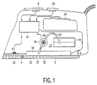
- FIG. 1 shows an embodiment of a steam iron in accordance with the invention.
- the steam iron comprises a conventional (thick) soleplate 2 which is heated by an electric heating element 4.
- the instantaneous temperature of the soleplate 2 is measured by means of a temperature sensor 6, for example a PTC resistor, an NTC resistor or a thermocouple element, which is thermally coupled to the soleplate 2.
- the desired soleplate temperature can be set by the user by means of a temperature selector or temperature control dial 8, but alternatively any other known control means such as push-buttons or touch controls can be used.
- a control circuit 10 compares the instantaneous temperature of the soleplate 10 with the desired temperature and controls the heat production of the heating element 4, for example by means of a triac in series with the heating element 4, in such a manner that the instantaneous temperature becomes equal to the desired temperature.
- a control circuit 10 compares the instantaneous temperature of the soleplate 10 with the desired temperature and controls the heat production of the heating element 4, for example by means of a triac in series with the heating element 4, in such a manner that the instantaneous temperature becomes equal to the desired temperature.
- a temperature sensor 6 and a triac it is possible to use a more conventional control by means of a thermostat to control the temperature of the soleplate 2.
- the steam iron further comprises a steam generator 12 having a water reservoir 14, a water pump 16 and a steam chamber 18 which is heated by the soleplate 2.
- the water pump 16 pumps water from the water reservoir 14 to the steam chamber 18 via a tube 20.
- the water evaporates in the steam chamber 18 and escapes via steam ports 22 formed in the soleplate 2.
- the supply of steam is controlled by means of an activation signal AS supplied by the control circuit 10 in response to a control signal from a control knob or control dial 26 by means of which the amount of steam to be produced can be set.
- the steam iron further comprises an optional hand sensor 24 arranged in the handle of the steam iron.
- the hand sensor can be of any known type, for example a capacitive sensor.
- the hand sensor 24 informs the control circuit 10 whether or not the steam iron is in use.
- the (increased) amount of water admitted to the steam chamber will cause a the temperature of the soleplate 2 to decrease. This is because the evaporation of the water requires energy which is extracted from the soleplate 2 to which the steam chamber 18 is thermally coupled. As a result of this, the temperature of the soleplate 2 decreases. The decrease is measured by the temperature sensor 6 and is reported to the control circuit 10, which responds thereto by increasing the power output of the heating element 4. A similar situation occurs in the case of a thermostat control.
- control circuit 10 can only respond when the temperature decrease of the soleplate 2 has already occurred, restoring the desired temperature of the soleplate 2 always being effected after the temperature decrease.
- the temperature of the soleplate 2 is subject to substantial temperature fluctuations, particularly upon a change-over from dry ironing to steam ironing and when steam blasts are given.
- the control circuit 10 comprises means which adapt the power output of the heating element 4 to the amount of steam to be produced.
- An amount of steam requested by means of the control dial 26 results in a given activation of the water pump 16. It is known how much water this water pump 16 (or any other supply device) conveys from the water reservoir 14 to the steam chamber 18.
- the instantaneous temperature of the soleplate 2 and the requested amount of steam it is possible to calculate how much extra heat the soleplate 2 should produce to compensate for the anticipated temperature decrease of the soleplate 2. This also depends on the construction of the steam iron. Factors which play a part are, for example, the thermal mass of the soleplate and the dimensions and the thermal coupling between the steam container 18 and the soleplate 2.
- the control circuit 10 sets the power output of the heating element 4 to another value in the case of a changed demand for steam production. More steam requires more power from the heating element.
- This change in power output of heating element 4 in response to a change in the desired steam production is effected directly, i.e. without intervention of the temperature control. For example, in the case of a change from dry ironing to steam ironing the power the power of the heating element 4 is increased immediately by a value adequate to compensate for the expected temperature decrease.
- the variation of the power of the heating element 4 can be effected in various ways. It is possible to connect one or more additional heating elements in order to meet the temporary higher demand for heat. A fine control is then possible by controlling the heat delivered by one of the additional heating elements by means of an electronic switch, for example on the basis of duty cycle control. Another possibility is to adapt the maximum power of the heating element 4 to the highest heat demand in the case of maximum steam production and at the highest ironing temperature and to control this power as required.
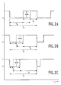
- Figures 2A, 2B and 2C show control signals for power control of the heating element 4 on the basis of duty cycle control, an electronic switch (not shown) connecting the heating element 4 to the mains voltage if the control signal has the value "1" and disconnects it from the mains voltage if the control signal has the value "0".
- the period of the control signal is T p .
- T a is the on time and T b is the off time.
- the sum of the on time T a and the off time T b is equal to the period T p .
- Figure 2A represents the situation during dry ironing.
- the duty cycle T a /T p then varies between two values indicated in broken lines. The variation is dependent on the temperature setting and/or the degree of cooling of the soleplate 2. It is to be noted that the values shown for the switching times have been given merely by way of example and may be different in actual practice.
- Figure 2B represents the situation in the case of steam ironing with little steam. In this case, the instant at which the control signal changes over from 0 to 1 has shifted to the left. which results in an increase of the duty cycle and, consequently, of the average power delivered by the heating element 4. The shift to the left, i.e. the offset, and the consequent power increase depends on the amount of steam set by means of the control dial 26.
- Figure 2C represents the situation in the case of steam ironing with much steam.
- the change-over point has shifted even more to the left (more offset) in order to meet the even greater heat demand.
- the shift of change-over point, and hence the offset depends on the steam production set by means of the control disc 26.
- the variation of the change-over point which is indicated in broken lines in Figures 2A, 2B and 2C and which is superposed on said shift, is caused by the temperature control, which is independent thereof.
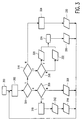
- Figure 3 is a flow chart of a control system for controlling the power of the heating element 4.
- T set is the desired temperature set by means of the temperature control dial 8
- T soleplate is the temperature of the soleplate 2 measured by means of the temperature sensor 6
- T err T soleplate - T set
- Dc1 is the offset in the duty cycle when the steam iron is in a rest position and is not used
- Dc2 is the offset in the duty cycle during steam ironing
- Dc3 is the offset in the duty cycle during ironing without steam.
- temperature setting T set of the soleplate 2 is determined. If it deviates too much from the desired temperature (block 304) it is examined whether the soleplate is too cold (block 306). If it is too cold, the full power is applied to heat the soleplate to the desired temperature (block 308), after which the block 302 is carried out again. If it is not too cold, the soleplate is too hot and should be allowed too cool down. This cooling down is expedited by evaporating water (fast cooling). The required amount of steam is calculated (block 310) and is generated by pumping water from the water reservoir 14 to the steam chamber 18. After this, the heating is turned off (block 314) and the program returns to the block 302.
- the temperature of the soleplate has come sufficiently close to the desired temperature (block 304) it is checked whether the hand sensor indicates that the steam iron is in use or not in use (block 316). If it is not in use, the steam production is turned off (block 328) and the power of the heating element 4 is set to a stand-by value of, for example, 100 W by selection of a suitable offset (block 330) and the program returns to the block 302. If the steam iron is in use it is checked whether steam is required (block 318). In this is not the case, the offset corresponding to dry ironing is selected (block 322); if steam is required, the offset corresponding to ironing with the selected amount of steam is chosen.
- the control circuit 10 calculates the duty cycle (block 326), after which the program returns to the block 302. If desired, the control circuit 10 can operate on a fuzzy logic basis, in which case for example T err and the temperature variation of the soleplate as a function of time are divided into classes.
- the sensor 24 in the handle serves to signal whether or not the iron is in use. Instead of or in addition to a motion sensor or a position sensor can be used. If the steam iron is equipped with a stand, the presence of the iron on the stand can also be signalled by means of a switch which cooperates with projection on or a recess in the stand.
Landscapes
- Engineering & Computer Science (AREA)
- Textile Engineering (AREA)
- Irons (AREA)
Abstract
Description
| | Inscription | |
| 300 | | |
| 302 | Read Tset | |
| 304 | -20°C < Terr < +20°C ? | |
| 306 | Tsoleplate > | |
| 308 | Output duty cycle = 1 | |
| 310 | Calculate amount of | |
| 312 | | |
| 314 | Output duty cycle = 0 | |
| 316 | Hand sensed ? | |
| 318 | Steam required ? | |
| 320 | | |
| 322 | | |
| 324 | | |
| 326 | | |
| 328 | No | |
| 330 | Output Dc1 |
Claims (6)
- A steam iron comprising: a soleplate (2); a heating element (4) for heating the soleplate (2); a control circuit (10) for controlling the temperature of the soleplate (2) by activation of the heating element (4); a steam generator (12) for generating steam, comprising a steam chamber (18) which is thermally coupled to the soleplate (2), a water reservoir (14) for holding the water to be evaporated, and a supply device (16, 20) for the controlled supply of water to be evaporated to the steam chamber (18); and means (26, 10) for activating the steam generator (12), characterized in that the control circuit (10) further comprises means (10, 318, 320, 322, 324, 326) for adaptation of the activation of the heating element (4) in response to the activation of the steam generator (12) in anticipation of the expected cooling-down of the soleplate (2) as a result of the supply of the water to be evaporated to the steam chamber (18).
- A steam iron as claimed in Claim 1, characterized in that the supply device comprises an electrical water pump (16).
- A steam iron as claimed in Claim 1 or 2, characterized in that the means (10) for adaptation operate on the basis of a duty cycle control of the activation of the heating element (4), the increase of the duty cycle being dependent upon the amount of steam to be generated.
- A steam iron as claimed in Claim 1, 2 or 3, characterized in that the control circuit (10) further comprises means (310, 312) for activating the supply device (16, 20) if the soleplate (2) has a temperature higher than a desired temperature.
- A steam iron as claimed in Claim 1, 2, 3 or 4, characterized in that the steam iron further comprises a sensor (24) for detecting whether the steam iron is in use.
- A steam iron as claimed in Claim 5, characterized in that the sensor is a hand sensor (24) arranged in a handle of the steam iron.
Priority Applications (1)
| Application Number | Priority Date | Filing Date | Title |
|---|---|---|---|
| EP98945483A EP0954630B1 (en) | 1997-10-29 | 1998-10-12 | Steam iron with anticipating power control |
Applications Claiming Priority (4)
| Application Number | Priority Date | Filing Date | Title |
|---|---|---|---|
| EP97202564 | 1997-10-29 | ||
| EP97202564 | 1997-10-29 | ||
| EP98945483A EP0954630B1 (en) | 1997-10-29 | 1998-10-12 | Steam iron with anticipating power control |
| PCT/IB1998/001591 WO1999022061A1 (en) | 1997-10-29 | 1998-10-12 | Steam iron with anticipating power control |
Publications (2)
| Publication Number | Publication Date |
|---|---|
| EP0954630A1 EP0954630A1 (en) | 1999-11-10 |
| EP0954630B1 true EP0954630B1 (en) | 2002-09-18 |
Family
ID=8228655
Family Applications (1)
| Application Number | Title | Priority Date | Filing Date |
|---|---|---|---|
| EP98945483A Expired - Lifetime EP0954630B1 (en) | 1997-10-29 | 1998-10-12 | Steam iron with anticipating power control |
Country Status (6)
| Country | Link |
|---|---|
| US (1) | US6079133A (en) |
| EP (1) | EP0954630B1 (en) |
| JP (1) | JP2001507271A (en) |
| CN (1) | CN1138886C (en) |
| DE (1) | DE69808046T2 (en) |
| WO (1) | WO1999022061A1 (en) |
Cited By (1)
| Publication number | Priority date | Publication date | Assignee | Title |
|---|---|---|---|---|
| WO2009083417A1 (en) * | 2007-12-28 | 2009-07-09 | BSH Bosch und Siemens Hausgeräte GmbH | Steam iron |
Families Citing this family (28)
| Publication number | Priority date | Publication date | Assignee | Title |
|---|---|---|---|---|
| SG83185A1 (en) * | 2000-01-25 | 2001-09-18 | Koninkl Philips Electronics Nv | Steam iron |
| US6453587B1 (en) * | 2001-05-18 | 2002-09-24 | Ehsan Alipour | Self lifting iron |
| WO2004009898A2 (en) * | 2002-07-24 | 2004-01-29 | Koninklijke Philips Electronics N.V. | Iron with fabric contact detector |
| US20060086712A1 (en) * | 2004-10-25 | 2006-04-27 | Feldmeier David C | Safety device for flat irons based on optical motion detection |
| EP1831450A2 (en) * | 2004-12-22 | 2007-09-12 | Koninklijke Philips Electronics N.V. | Steam ironing device |
| EP1896648A2 (en) * | 2005-05-13 | 2008-03-12 | Unovo Inc. | Automatic standby electric clothes iron |
| GB2469768A (en) * | 2005-11-18 | 2010-10-27 | Jemella Ltd | Electric hair iron with voltage control means |
| US7516565B1 (en) | 2008-03-20 | 2009-04-14 | Samson Tsen | Steam channeling structure |
| CN201176537Y (en) | 2008-03-27 | 2009-01-07 | 程进村 | Vapour transferring structure |
| DE102012201234B4 (en) * | 2012-01-27 | 2018-03-29 | BSH Hausgeräte GmbH | Electrically heatable device with steam generator and method for controlling an electrically heatable device with steam generator |
| JP6383934B2 (en) * | 2013-06-20 | 2018-09-05 | パナソニックIpマネジメント株式会社 | Steam blower |
| JP6201143B2 (en) * | 2013-06-20 | 2017-09-27 | パナソニックIpマネジメント株式会社 | Steam blower |
| EP2832922B1 (en) * | 2013-07-30 | 2016-06-22 | BSH Hausgeräte GmbH | Steam iron |
| EP3222769B1 (en) | 2014-11-22 | 2020-04-08 | Foshan Shunde Midea Electrical Heating Appliances Manufacturing Co., Limited | Control method and control system for clothing care machine and clothing care machine |
| US20180051410A1 (en) * | 2015-03-30 | 2018-02-22 | Koninklijke Philips N.V. | An ironing appliance with means for controlling the heating power |
| EP3098345B1 (en) * | 2015-05-29 | 2019-07-03 | Sda Factory Victoria Slu | Steam iron and method for operating a steam iron |
| US10330308B2 (en) * | 2015-12-30 | 2019-06-25 | Koninklijke Philips N.V. | Apparatus for generating steam |
| CN107044044B (en) * | 2016-02-06 | 2019-07-19 | 漳州灿坤实业有限公司 | It is capable of the vapour iron and synchronous regulation mechanism of synchronous adjustment steam and temperature |
| EP3445907B1 (en) * | 2016-11-01 | 2019-10-02 | Koninklijke Philips N.V. | Stain removal accessory |
| WO2018166571A1 (en) * | 2017-03-13 | 2018-09-20 | Alfred Kärcher SE & Co. KG | Steam generating device |
| EP3502345A1 (en) | 2017-12-22 | 2019-06-26 | Koninklijke Philips N.V. | Textile treatment device and portable device for obtaining a classification of a textile |
| FR3081888B1 (en) * | 2018-05-31 | 2020-05-15 | Seb S.A. | IRONING APPARATUS HAVING A STEAM CONTROL MEMBER |
| FR3081887B1 (en) * | 2018-05-31 | 2020-05-15 | Seb S.A. | IRONING APPARATUS HAVING A STEAM CONTROL MEMBER |
| US11505893B2 (en) | 2020-03-04 | 2022-11-22 | Conair Llc | Garment steaming device |
| USD930925S1 (en) | 2020-03-04 | 2021-09-14 | Conair Corporation | Garment steamer |
| US11629453B2 (en) | 2020-03-04 | 2023-04-18 | Conair Llc | Garment steaming device |
| US11261561B2 (en) | 2020-03-04 | 2022-03-01 | Conair Llc | Garment steaming device |
| US11306429B2 (en) | 2020-03-04 | 2022-04-19 | Conair Llc | Garment steaming device |
Family Cites Families (11)
| Publication number | Priority date | Publication date | Assignee | Title |
|---|---|---|---|---|
| GB2199962A (en) * | 1987-01-13 | 1988-07-20 | Morphy Ltd Richards | Electric iron |
| JP2603606B2 (en) * | 1988-08-25 | 1997-04-23 | 東芝ケミカル株式会社 | Manufacturing method of multilayer printed wiring board |
| NL8900749A (en) * | 1989-03-28 | 1990-10-16 | Philips Nv | STEAM IRON. |
| IT1244228B (en) * | 1990-03-08 | 1994-07-08 | Giulia Dassa | ELECTRIC IRON WITH INTERNAL VAPORIZATION APPARATUS |
| DE4214564C1 (en) * | 1992-05-08 | 1993-09-02 | Rowenta-Werke Gmbh, 6050 Offenbach, De | |
| JPH05329300A (en) * | 1992-06-02 | 1993-12-14 | Juki Corp | Method for controlling temperature display of iron and device therefor |
| JP3174799B2 (en) * | 1992-11-30 | 2001-06-11 | 東芝ホームテクノ株式会社 | Steam iron |
| DE4433915C2 (en) * | 1994-09-23 | 2000-01-05 | Braun Gmbh | Active cooling of a steam iron sole with safety shutdown |
| BR9603891A (en) * | 1995-01-23 | 1997-10-07 | Philips Electronics Nv | Steam iron |
| WO1996023098A1 (en) * | 1995-01-23 | 1996-08-01 | Philips Electronics N.V. | Steam iron having a fabric temperature sensor for controlling steam production |
| DE19542916A1 (en) * | 1995-11-17 | 1997-05-22 | Ernst Ulrich Ries | Safety device for electrical iron |
-
1998
- 1998-10-12 WO PCT/IB1998/001591 patent/WO1999022061A1/en active IP Right Grant
- 1998-10-12 DE DE69808046T patent/DE69808046T2/en not_active Expired - Lifetime
- 1998-10-12 EP EP98945483A patent/EP0954630B1/en not_active Expired - Lifetime
- 1998-10-12 JP JP52356899A patent/JP2001507271A/en active Pending
- 1998-10-12 CN CNB98801601XA patent/CN1138886C/en not_active Expired - Lifetime
- 1998-10-28 US US09/181,157 patent/US6079133A/en not_active Expired - Lifetime
Cited By (1)
| Publication number | Priority date | Publication date | Assignee | Title |
|---|---|---|---|---|
| WO2009083417A1 (en) * | 2007-12-28 | 2009-07-09 | BSH Bosch und Siemens Hausgeräte GmbH | Steam iron |
Also Published As
| Publication number | Publication date |
|---|---|
| DE69808046D1 (en) | 2002-10-24 |
| CN1138886C (en) | 2004-02-18 |
| WO1999022061A1 (en) | 1999-05-06 |
| EP0954630A1 (en) | 1999-11-10 |
| US6079133A (en) | 2000-06-27 |
| DE69808046T2 (en) | 2003-05-22 |
| JP2001507271A (en) | 2001-06-05 |
| CN1242810A (en) | 2000-01-26 |
Similar Documents
| Publication | Publication Date | Title |
|---|---|---|
| EP0954630B1 (en) | Steam iron with anticipating power control | |
| EP0390264B1 (en) | Steam iron | |
| JP4553541B2 (en) | Steam iron | |
| US4638147A (en) | Microprocessor controlled through-flow electric water heater | |
| JPH06209857A (en) | Coffee urn | |
| AU2008202833B2 (en) | Dual heater appliance such as a coffee machine | |
| US4302662A (en) | Control instrument for electric hot plates | |
| JPH09510905A (en) | Quick cooling steam iron | |
| JPS61154631A (en) | Boiling and cooking process control apparatus | |
| US7472504B2 (en) | Steam iron having two flat resistive elements for heating the soleplate | |
| GB2184526A (en) | Water heaters | |
| JPH09245956A (en) | Induction heating cooker | |
| JPS6249050B2 (en) | ||
| JP3044946B2 (en) | Iron | |
| JP2924414B2 (en) | Iron | |
| JPH0785949A (en) | Electric heater apparatus | |
| JPH04319398A (en) | Iron device | |
| JP3044965B2 (en) | Iron | |
| JPH05317596A (en) | Iron | |
| JP2744223B2 (en) | Cordless iron | |
| JP2558708B2 (en) | Steam iron | |
| JPH0731799A (en) | Iron device | |
| JPH0790095B2 (en) | Steam iron | |
| JP2001061660A (en) | Electric kettle | |
| JPH11239700A (en) | Iron |
Legal Events
| Date | Code | Title | Description |
|---|---|---|---|
| PUAI | Public reference made under article 153(3) epc to a published international application that has entered the european phase |
Free format text: ORIGINAL CODE: 0009012 |
|
| AK | Designated contracting states |
Kind code of ref document: A1 Designated state(s): DE FR GB IT |
|
| 17P | Request for examination filed |
Effective date: 19991108 |
|
| GRAG | Despatch of communication of intention to grant |
Free format text: ORIGINAL CODE: EPIDOS AGRA |
|
| 17Q | First examination report despatched |
Effective date: 20011113 |
|
| GRAG | Despatch of communication of intention to grant |
Free format text: ORIGINAL CODE: EPIDOS AGRA |
|
| GRAH | Despatch of communication of intention to grant a patent |
Free format text: ORIGINAL CODE: EPIDOS IGRA |
|
| GRAH | Despatch of communication of intention to grant a patent |
Free format text: ORIGINAL CODE: EPIDOS IGRA |
|
| GRAA | (expected) grant |
Free format text: ORIGINAL CODE: 0009210 |
|
| AK | Designated contracting states |
Kind code of ref document: B1 Designated state(s): DE FR GB IT |
|
| REG | Reference to a national code |
Ref country code: GB Ref legal event code: FG4D |
|
| REF | Corresponds to: |
Ref document number: 69808046 Country of ref document: DE Date of ref document: 20021024 |
|
| ET | Fr: translation filed | ||
| PLBE | No opposition filed within time limit |
Free format text: ORIGINAL CODE: 0009261 |
|
| STAA | Information on the status of an ep patent application or granted ep patent |
Free format text: STATUS: NO OPPOSITION FILED WITHIN TIME LIMIT |
|
| 26N | No opposition filed |
Effective date: 20030619 |
|
| REG | Reference to a national code |
Ref country code: DE Ref legal event code: R082 Ref document number: 69808046 Country of ref document: DE Representative=s name: MEYER, MICHAEL, DIPL.-ING., DE |
|
| REG | Reference to a national code |
Ref country code: DE Ref legal event code: R082 Ref document number: 69808046 Country of ref document: DE Representative=s name: MEYER, MICHAEL, DIPL.-ING., DE Effective date: 20140331 Ref country code: DE Ref legal event code: R081 Ref document number: 69808046 Country of ref document: DE Owner name: KONINKLIJKE PHILIPS N.V., NL Free format text: FORMER OWNER: KONINKLIJKE PHILIPS ELECTRONICS N.V., EINDHOVEN, NL Effective date: 20140331 |
|
| REG | Reference to a national code |
Ref country code: FR Ref legal event code: CD Owner name: KONINKLIJKE PHILIPS N.V., NL Effective date: 20141126 Ref country code: FR Ref legal event code: CA Effective date: 20141126 |
|
| REG | Reference to a national code |
Ref country code: FR Ref legal event code: PLFP Year of fee payment: 18 |
|
| REG | Reference to a national code |
Ref country code: FR Ref legal event code: PLFP Year of fee payment: 19 |
|
| REG | Reference to a national code |
Ref country code: FR Ref legal event code: PLFP Year of fee payment: 20 |
|
| PGFP | Annual fee paid to national office [announced via postgrant information from national office to epo] |
Ref country code: FR Payment date: 20171031 Year of fee payment: 20 |
|
| PGFP | Annual fee paid to national office [announced via postgrant information from national office to epo] |
Ref country code: IT Payment date: 20171024 Year of fee payment: 20 Ref country code: GB Payment date: 20171101 Year of fee payment: 20 |
|
| PGFP | Annual fee paid to national office [announced via postgrant information from national office to epo] |
Ref country code: DE Payment date: 20171229 Year of fee payment: 20 |
|
| REG | Reference to a national code |
Ref country code: DE Ref legal event code: R071 Ref document number: 69808046 Country of ref document: DE |
|
| REG | Reference to a national code |
Ref country code: GB Ref legal event code: PE20 Expiry date: 20181011 |
|
| PG25 | Lapsed in a contracting state [announced via postgrant information from national office to epo] |
Ref country code: GB Free format text: LAPSE BECAUSE OF EXPIRATION OF PROTECTION Effective date: 20181011 |