JP2008514030A - High power small area III-nitride LED - Google Patents
High power small area III-nitride LED Download PDFInfo
- Publication number
- JP2008514030A JP2008514030A JP2007533549A JP2007533549A JP2008514030A JP 2008514030 A JP2008514030 A JP 2008514030A JP 2007533549 A JP2007533549 A JP 2007533549A JP 2007533549 A JP2007533549 A JP 2007533549A JP 2008514030 A JP2008514030 A JP 2008514030A
- Authority
- JP
- Japan
- Prior art keywords
- light emitting
- emitting diode
- radiant flux
- unit area
- diode according
- Prior art date
- Legal status (The legal status is an assumption and is not a legal conclusion. Google has not performed a legal analysis and makes no representation as to the accuracy of the status listed.)
- Pending
Links
Images


Classifications
-
- H—ELECTRICITY
- H01—ELECTRIC ELEMENTS
- H01L—SEMICONDUCTOR DEVICES NOT COVERED BY CLASS H10
- H01L33/00—Semiconductor devices with at least one potential-jump barrier or surface barrier specially adapted for light emission; Processes or apparatus specially adapted for the manufacture or treatment thereof or of parts thereof; Details thereof
- H01L33/36—Semiconductor devices with at least one potential-jump barrier or surface barrier specially adapted for light emission; Processes or apparatus specially adapted for the manufacture or treatment thereof or of parts thereof; Details thereof characterised by the electrodes
- H01L33/40—Materials therefor
- H01L33/405—Reflective materials
-
- H—ELECTRICITY
- H01—ELECTRIC ELEMENTS
- H01L—SEMICONDUCTOR DEVICES NOT COVERED BY CLASS H10
- H01L33/00—Semiconductor devices with at least one potential-jump barrier or surface barrier specially adapted for light emission; Processes or apparatus specially adapted for the manufacture or treatment thereof or of parts thereof; Details thereof
- H01L33/02—Semiconductor devices with at least one potential-jump barrier or surface barrier specially adapted for light emission; Processes or apparatus specially adapted for the manufacture or treatment thereof or of parts thereof; Details thereof characterised by the semiconductor bodies
- H01L33/20—Semiconductor devices with at least one potential-jump barrier or surface barrier specially adapted for light emission; Processes or apparatus specially adapted for the manufacture or treatment thereof or of parts thereof; Details thereof characterised by the semiconductor bodies with a particular shape, e.g. curved or truncated substrate
-
- H—ELECTRICITY
- H01—ELECTRIC ELEMENTS
- H01L—SEMICONDUCTOR DEVICES NOT COVERED BY CLASS H10
- H01L2224/00—Indexing scheme for arrangements for connecting or disconnecting semiconductor or solid-state bodies and methods related thereto as covered by H01L24/00
- H01L2224/01—Means for bonding being attached to, or being formed on, the surface to be connected, e.g. chip-to-package, die-attach, "first-level" interconnects; Manufacturing methods related thereto
- H01L2224/42—Wire connectors; Manufacturing methods related thereto
- H01L2224/47—Structure, shape, material or disposition of the wire connectors after the connecting process
- H01L2224/48—Structure, shape, material or disposition of the wire connectors after the connecting process of an individual wire connector
- H01L2224/481—Disposition
- H01L2224/48151—Connecting between a semiconductor or solid-state body and an item not being a semiconductor or solid-state body, e.g. chip-to-substrate, chip-to-passive
- H01L2224/48221—Connecting between a semiconductor or solid-state body and an item not being a semiconductor or solid-state body, e.g. chip-to-substrate, chip-to-passive the body and the item being stacked
- H01L2224/48245—Connecting between a semiconductor or solid-state body and an item not being a semiconductor or solid-state body, e.g. chip-to-substrate, chip-to-passive the body and the item being stacked the item being metallic
- H01L2224/48247—Connecting between a semiconductor or solid-state body and an item not being a semiconductor or solid-state body, e.g. chip-to-substrate, chip-to-passive the body and the item being stacked the item being metallic connecting the wire to a bond pad of the item
-
- H—ELECTRICITY
- H01—ELECTRIC ELEMENTS
- H01L—SEMICONDUCTOR DEVICES NOT COVERED BY CLASS H10
- H01L2924/00—Indexing scheme for arrangements or methods for connecting or disconnecting semiconductor or solid-state bodies as covered by H01L24/00
- H01L2924/15—Details of package parts other than the semiconductor or other solid state devices to be connected
- H01L2924/181—Encapsulation
-
- H—ELECTRICITY
- H01—ELECTRIC ELEMENTS
- H01L—SEMICONDUCTOR DEVICES NOT COVERED BY CLASS H10
- H01L33/00—Semiconductor devices with at least one potential-jump barrier or surface barrier specially adapted for light emission; Processes or apparatus specially adapted for the manufacture or treatment thereof or of parts thereof; Details thereof
- H01L33/02—Semiconductor devices with at least one potential-jump barrier or surface barrier specially adapted for light emission; Processes or apparatus specially adapted for the manufacture or treatment thereof or of parts thereof; Details thereof characterised by the semiconductor bodies
- H01L33/26—Materials of the light emitting region
- H01L33/30—Materials of the light emitting region containing only elements of group III and group V of the periodic system
- H01L33/32—Materials of the light emitting region containing only elements of group III and group V of the periodic system containing nitrogen
Abstract
単位面積当たり有利な出力を有する発光ダイオードを開示する。このダイオードは、100,000平方ミクロン未満の面積を含み、4.0ボルト未満の順方向電圧で動作し、20ミリアンペアの駆動電流において少なくとも24ミリワットの放射束を生成し、約395及び540ナノメートルの間の主波長において発光する。Disclosed are light emitting diodes having advantageous power per unit area. The diode includes an area of less than 100,000 square microns, operates at a forward voltage of less than 4.0 volts, produces a radiant flux of at least 24 milliwatts at a drive current of 20 milliamps, and is approximately 395 and 540 nanometers. Emits light at the dominant wavelength.
Description
本発明は、発光ダイオード(LED)に関し、特に、炭化珪素基板上にIII族窒化物のアクティブ部分が形成さたLEDに関する。 The present invention relates to a light emitting diode (LED), and more particularly to an LED having a group III nitride active portion formed on a silicon carbide substrate.
発光技術
多くの用途に向けられる発光デバイスは、数種類の広い分類に分けられる。白熱照明は、金属フィラメントを加熱することによって、通常では金属フィラメントに電流を通すことによって生成する。加熱されたフィラメントは光を放出する。家庭用及びその他の室内用照明は、広く行き渡っている白熱照明の用途の1つである。「ハロゲン」照明は、全体的に同じ原理で作用するが、効率が高い。蛍光発光は、蒸気(通例、水銀を含有する)を印加電位差で励起することによって発生する。次いで、励起した蒸気から放出される光子が燐光体(蛍光体)に衝突して可視光を放出する。蛍光発光も、家庭、事務所、及び種々のその他の用途において広く行き渡っている。
Light-emitting technology Light-emitting devices directed to many applications can be divided into several broad categories. Incandescent illumination is generated by heating a metal filament, usually by passing an electric current through the metal filament. The heated filament emits light. Home and other indoor lighting is one of the widespread uses of incandescent lighting. “Halogen” illumination works on the same principle as a whole, but is more efficient. Fluorescence emission is generated by exciting vapor (typically containing mercury) with an applied potential difference. Next, photons emitted from the excited vapor collide with the phosphor (phosphor) to emit visible light. Fluorescence emission is also widespread in homes, offices, and various other applications.
発光ダイオード
発光ダイオード(LED)は、p−n接合半導体ダイオードであり、順方向にバイアスされると、光子を放出する。つまり、発光ダイオードが生成する光は、半導体材料における電子の移動に基づく。したがって、LEDは、蒸気も燐光体も必要としない(しかし、これらと共に用いることはできる)。これらは、殆どの半導体系デバイスにおける所望の特性を共有しており、高効率(それらの放出には熱が殆ど又は全く含まれない)、高信頼性、及び長寿命が含まれる。例えば、典型的なLEDの故障間平均時間は、約100,000〜1,000,000時間の間であり、LEDの控えめな半減期でも、約50,000時間である。
Light emitting diodes Light emitting diodes (LEDs) are pn junction semiconductor diodes that emit photons when forward biased. That is, the light generated by the light emitting diode is based on the movement of electrons in the semiconductor material. Thus, LEDs do not require vapors or phosphors (but can be used with them). These share the desired properties in most semiconductor-based devices and include high efficiency (their emissions contain little or no heat), high reliability, and long life. For example, the average time between failures of a typical LED is between about 100,000 and 1,000,000 hours, and even the modest half-life of the LED is about 50,000 hours.
具体的には、LEDが放出する光の周波数は、材料における許容エネルギ・レベル間におけるエネルギ差、即ち、バンドギャップと呼ばれる特性に基づいている(一方、周波数は、周知の物理法則にしたがって、波長及び色に直接関係する)。バンドギャップは、半導体材料及びそのドーピングの基礎的な固有特性(property)である。つまり、シリコン(Si:バンドギャップは1.12電子ボルト(eV))に形成されたLEDは、スペクトルの赤外線部分においてエネルギ遷移を有する。このため、シリコン系ダイオードは、人の目に対する可視性が重要でないか、又は特別に望まれない低コスト・センサのような品目に用いられる。ガリウム砒素(バンドギャップは1.42eV)に形成されたLED、又は更に一般的に、シリコン系砒化アルミニウム・ガリウム(AlGaAs)に形成されたLEDは、スペクトルの可視部分で発光するが、赤外線や赤色及び黄色光を生成するような低い周波数帯である。 Specifically, the frequency of light emitted by an LED is based on an energy difference between acceptable energy levels in the material, ie, a characteristic called a band gap (while the frequency is a wavelength according to well-known physical laws). And directly related to color). Band gap is a fundamental property of semiconductor materials and their doping. That is, an LED formed in silicon (Si: band gap is 1.12 electron volts (eV)) has an energy transition in the infrared portion of the spectrum. For this reason, silicon-based diodes are used in items such as low-cost sensors where visibility to the human eye is not important or not particularly desirable. LEDs formed in gallium arsenide (bandgap is 1.42 eV), or more generally LEDs formed in silicon-based aluminum gallium arsenide (AlGaAs), emit light in the visible part of the spectrum, but not in the infrared or red And a low frequency band that produces yellow light.
一方、緑、青、及び紫外線(UV)光子は、可視スペクトル以内の(及びこれを超える)高い周波数の色を表すので、これらは、バンドギャップが少なくとも約2.2eVのLEDでなければ生成できない。このような材料は、ダイアモンド(5.47eV)、炭化珪素(2.99eV)、及びGaN(3.4eV)のようなIII族窒化物を含む。緑、青、又は紫外線光自体を生成することに加えて、バンドギャップが広いLEDを赤色及び緑色LEDと組み合わせて、白色を生成することができ、蛍光体と組み合わせ、青色光又はUV光あるいは双方によって励起させて白色光を生成することができる。 On the other hand, green, blue, and ultraviolet (UV) photons represent high frequency colors within (and beyond) the visible spectrum, so they can only be produced with LEDs having a band gap of at least about 2.2 eV. . Such materials include group III nitrides such as diamond (5.47 eV), silicon carbide (2.99 eV), and GaN (3.4 eV). In addition to generating green, blue, or ultraviolet light itself, wide band gap LEDs can be combined with red and green LEDs to generate white, combined with phosphors, blue light or UV light or both Can produce white light upon excitation.
様々な理由のために、III族窒化物組成(即ち、周期表のIII族)、特に、GaN、AlGaN、InGaN、及びAlInGaNは、青色発光LEDには特に有用である。1つの利点をあげると、これらは「直接」エミッタ(発光器)であることであり、バンドギャップ間を渡る電子遷移が発生すると、エネルギの多くが光となって放出されることを意味する。比較すると、「間接」エミッタ(炭化珪素のような)は、そのエネルギを部分的に光(光子)として放出し、大部分を振動エネルギ(光子)として放出する。したがって、III族窒化物では、間接遷移材料を越えた、効率上の利点が得られる。 For various reasons, Group III nitride compositions (ie, Group III of the periodic table), particularly GaN, AlGaN, InGaN, and AlInGaN, are particularly useful for blue light emitting LEDs. One advantage is that these are “direct” emitters (emitters), meaning that when an electron transition occurs between the band gaps, much of the energy is emitted as light. By comparison, an “indirect” emitter (such as silicon carbide) emits its energy partially as light (photons) and most as vibration energy (photons). Thus, III-nitrides provide efficiency advantages over indirect transition materials.
別の利点をあげると、三元又は四元III族材料(例えば、AlGaN、InGaN、AlInGaN)のバンドギャップは、含まれるIII族元素の原子分率によって左右される。つまり、発光の波長(色)は、三元又は四元窒化物における各III族元素の原子分率を制御することにより(制限内の範囲で)自由に選ぶことができる。 Another advantage is that the band gap of a ternary or quaternary group III material (eg, AlGaN, InGaN, AlInGaN) depends on the atomic fraction of the group III element involved. That is, the wavelength (color) of light emission can be freely selected (within a limit) by controlling the atomic fraction of each group III element in the ternary or quaternary nitride.
しかしながら、広バンドギャップ半導体は、以前から、ガリウム砒素又は燐化ガリウム(GaP)よりも、生産及び加工が困難であった。その結果、UV発光LEDは、GaP系LEDよりも市場への登場が遅れている。例えば、炭化珪素は物理的に非常に硬質であり、溶解フェーズ(相)がなく、エピタキシャル又は昇華成長のためには高温が必要となる(約1500〜2000℃程度)。III族窒化物は、その融点において、比較的大きな窒素蒸気圧を有し、このため溶融物から成長することが同様に困難又は不可能である。加えて、p型窒化ガリウム(及びその他のIII族窒化物)を得ることが困難であるために、長年にわたってダイオードの生産に対する障壁となっていた。このため、青色及び白色発光LEDが市販されるようになったのは、GaP系及びGaAs系LEDの対応する市販よりも最近のことである。 However, wide bandgap semiconductors have long been more difficult to produce and process than gallium arsenide or gallium phosphide (GaP). As a result, UV light-emitting LEDs have been delayed in the market than GaP-based LEDs. For example, silicon carbide is physically very hard, does not have a melting phase, and requires a high temperature for epitaxial or sublimation growth (about 1500 to 2000 ° C.). Group III nitrides have a relatively high nitrogen vapor pressure at their melting point, which makes it equally difficult or impossible to grow from the melt. In addition, the difficulty in obtaining p-type gallium nitride (and other group III nitrides) has long been a barrier to diode production. For this reason, blue and white light emitting LEDs have become commercially available more recently than the corresponding commercially available GaP and GaAs LEDs.
しかしながら、更に最近の開発に基づいて、III族窒化物に基づく青色LED及び派生的な白色発光ソリッド・ステート・ランプが、ソリッド・ステート照明用途において、徐々に広まりつつある。 However, based on more recent developments, group III nitride based blue LEDs and derivative white light emitting solid state lamps are gradually becoming more widespread in solid state lighting applications.
出力光の品質
比較及びその他の関連する目的のために、照明は通例その出力で定量化されている。典型的な測定単位の1つにルーメンがあり、1カンデラ(cd)強度の均一点光源によって単位立体角で放出された光に等しい光束の単位と定義されている。一方、カンデラは、国際単位系における光強度の基本単位であり、周波数540×1012の単色光線を放出する光源の所与の方向における光強度に等しく、その方向に単位立体角当たり1/683の放射強度を有する。
Illumination is typically quantified at its output for output light quality comparison and other related purposes. One typical unit of measurement is lumen, which is defined as the unit of luminous flux equal to the light emitted at a unit solid angle by a uniform point light source of 1 candela (cd) intensity. On the other hand, the candela is the basic unit of light intensity in the international unit system, and is equal to the light intensity in a given direction of a light source emitting a monochromatic ray having a frequency of 540 × 10 12 , and in that direction 1/683 per unit solid angle The radiation intensity is
ルーメンを測定単位として用いると、1200〜1800ルーメンの強度は、白熱電球に典型的であり、1000〜6000ルーメン(状況によって異なる)は、自然の白昼光において典型的である。しかしながら、発光ダイオードは、強度が遥かに小さく、例えば、約10〜100ルーメン程度である。理由の1つに、そのサイズが小さいことがあげられる。このため、単一(又は小集団)のLEDに合う用途は、以前より、照明(読むためのランプ)ではなく、指示(例えば、ハンドヘルド計算機のレジスタ)に重点が置かれていた。青色LED及び対応する白色発光デバイスが利用可能となって、照明の目的のためのこのようなLEDの市場入手可能性が広がったが、所望の出力を得るためには、数個(又はそれ以上)のLEDを纏めて使用しているのが通例である。 Using lumens as a unit of measure, intensities of 1200-1800 lumens are typical for incandescent bulbs, and 1000-6000 lumens (depending on the circumstances) are typical in natural daylight. However, light emitting diodes are much less intense, for example about 10 to 100 lumens. One reason is that the size is small. For this reason, applications that fit a single (or small group) of LEDs have traditionally focused on instructions (eg, handheld calculator registers) rather than illumination (lamps for reading). While blue LEDs and corresponding white light emitting devices have become available, the market availability of such LEDs for lighting purposes has expanded, but several (or more) have been obtained to obtain the desired output. ) LEDs are usually used together.
LEDは、その典型的なサイズ及び構造のために、ルーメン以外の単位で出力を測定する場合が多い。加えて、LEDの出力は、印加電流にも左右され、一方印加電流はダイオード間に印加される電位差によって左右される。このため、LEDの出力は、その放射束(Rf)と呼ばれることが多く、標準的な20ミリアンペア(mA)の駆動電流におけるミリワット(mW)単位で表される。 Due to their typical size and structure, LEDs often measure their output in units other than lumens. In addition, the output of the LED depends on the applied current, while the applied current depends on the potential difference applied between the diodes. For this reason, the output of an LED is often referred to as its radiant flux (R f ) and is expressed in milliwatts (mW) at a standard 20 milliamp (mA) drive current.
特に、青色LED及びそれらに関係する派生デバイスは、増々消費者用電子デバイス、特に小型ディスプレイに含まれる頻度が高くなりつつある。広く普及している例には、コンピュータ画面、パーソナル・ディジタル・アシスタント(「PDA」)、及びセルラ・フォンが含まれる。一方、これらの小型デバイスのため、サイズ(「フットプリント」)を縮小したLEDが求められることになった。しかしながら、このようなLEDであっても、低順方向電圧(Vf)及び高光出力で動作しなければならないことに変わりはない。今日まで、残念ながら、III族窒化物デバイスのサイズを縮小すると、その順方向電圧が増大し、その放射束が減少する傾向があった。
したがって、広バンドギャップ材料内に形成した小型LEDの出力を連続的に改善することが求められている。
In particular, blue LEDs and related devices associated with them are increasingly being included in consumer electronic devices, particularly small displays. Widespread examples include computer screens, personal digital assistants (“PDAs”), and cellular phones. On the other hand, for these small devices, LEDs with reduced size ("footprint") have been sought. However, even such an LED must operate at a low forward voltage (V f ) and high light output. To date, unfortunately, reducing the size of the III-nitride device tended to increase its forward voltage and decrease its radiant flux.
Therefore, there is a need to continuously improve the output of small LEDs formed in wide band gap materials.
要約すると、本発明は、小型で、順方向電圧が低く、光出力が大きい発光ダイオードである。
別の態様では、本発明は、単位面積当たり有利な出力を有する発光ダイオードである。このダイオードは、100,000平方ミクロン未満の面積、4.0ボルト未満の順方向電圧、20ミリアンペアの駆動電流において少なくとも24ミリワットの放射束、ならびに約395及び540ナノメートルの間の主波長を含む。
In summary, the present invention is a light emitting diode that is small, has a low forward voltage, and a high light output.
In another aspect, the present invention is a light emitting diode having an advantageous output per unit area. The diode includes an area of less than 100,000 square microns, a forward voltage of less than 4.0 volts, a radiant flux of at least 24 milliwatts at a drive current of 20 milliamps, and a dominant wavelength between about 395 and 540 nanometers. .
別の態様では、本発明は、100,000μ2未満の面積を有するダイと、ダイを封入する5mmパッケージと、4.0ボルト未満の順方向電圧と、約420及び465nmの間の波長、及び20ミリアンペアの駆動電流において、45パーセント(45%)よりも大きな外部量子効率とを有する。
別の態様では、本発明は、5mm(T1-3/4)ポリマ・パッケージと、パッケージ内にあり、面積が100,000平方ミクロン未満のダイと、4.0ボルト未満の順方向電圧と、20ミリアンペアの駆動電流において少なくとも24ミリワットの放射束と、約395及び540nmの間の主波長とを含む発光ダイオードである。
In another aspect, the present invention includes: a die having an area of less than 100,000Myu 2, and 5mm package encapsulating the die, the forward voltage of less than 4.0 volts, the wavelength of between about 420 and 465 nm, and It has an external quantum efficiency greater than 45 percent (45%) at a drive current of 20 milliamps.
In another aspect, the invention provides a 5 mm (T1-3 / 4) polymer package, a die within the package and having an area less than 100,000 square microns, a forward voltage less than 4.0 volts, A light emitting diode comprising a radiant flux of at least 24 milliwatts at a driving current of 20 milliamps and a dominant wavelength between about 395 and 540 nm.
別の態様では、本発明は、導電性炭化珪素基板と、炭化珪素基板上にあり、該基板と共にダイを規定する、p型及びn型それぞれのIII族窒化物層と、炭化珪素基板及びIII族窒化物層に対して垂直に配向されているオーミック・コンタクトと、455及び465nmの間の主波長と、基板、III族窒化物層、及びオーミック・コンタクトの一部を封入するポリマ・パッケージと、20ミリアンペアの駆動電流において発光面の1平方ミリメートル当たり少なくとも270ミリワットのパッケージからの放射束とを含む発光ダイオードである。
本発明の前述のならびにその他の目的及び利点、更にこれらを遂行する方法は、添付図面と関連付けた以下の詳細な説明を基にして、明確となるであろう。
In another aspect, the present invention provides a conductive silicon carbide substrate, a p-type and an n-type group III-nitride layer on the silicon carbide substrate and defining a die with the substrate, a silicon carbide substrate and III An ohmic contact oriented perpendicular to the group nitride layer, a dominant wavelength between 455 and 465 nm, and a polymer package encapsulating the substrate, the group III nitride layer, and a portion of the ohmic contact; A radiant flux from a package of at least 270 milliwatts per square millimeter of light emitting surface at a drive current of 20 milliamps.
The foregoing and other objects and advantages of the invention, as well as the manner in which they are accomplished, will become apparent based on the following detailed description taken in conjunction with the accompanying drawings.
本発明は、小型で、順方向電圧が低く、光出力が高く、そのため効率が高く、単位面積当たりの出力が大きい発光ダイオードである。
背景において明記したように、本発明の多数の構造的特徴が、本願と同じ譲受人に譲渡され同時係属中の米国特許出願第10/951,042号に明記されている。
The present invention is a light emitting diode that is compact, has low forward voltage, high light output, and therefore high efficiency and high output per unit area.
As specified in the background, numerous structural features of the present invention are specified in co-pending US patent application Ser. No. 10 / 951,042, assigned to the same assignee as the present application.
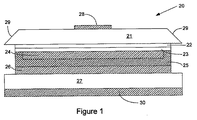
更に詳しく説明すると、図1は、本発明の性能特性を有し、全体的に20で示す発光ダイオードの断面図である。ダイオード20は、透明炭化珪素基板21を含み、好ましくは、単結晶であり、3C、4H、6H、及び15Rプロトタイプの炭化珪素から選択したプロトタイプを有し、本発明に関しては4Hが好ましいことが多い。図1はダイオード20を「フリップ・チップ」配向(即ち、アクティブ相を基板の下側にして用いるように実装されている)で図示しているので、基板21が、ダイオード20の底部ではなく最上部にある。この配向では、SiC基板はLEDの主要放出面となる。勿論、発光ダイオードは、最終使用において、多数の異なる位置及び配向で配置できることは言うまでもない。したがって、ダイオード20の要素に関して、用語「最上部」及び「底部」は、相対的であり、構造的な意味で全体的にデバイスの配向を示すものとする。このような用語の使用は、当技術分野では慣習となっており、周知であり、更に明細書における文脈からも明白である。
More specifically, FIG. 1 is a cross-sectional view of a light emitting diode generally indicated at 20 having the performance characteristics of the present invention. The
ダイオードは、少なくとも1つ、好ましくは数層の発光(「アクティブ」)部を形成する層を含む。図1には、n型層21及びp型層22の2つの層が示されている。これら導電型が逆の層は、電流がダイオードを通過する機会を与え、その結果得られる電子及び正孔の結合により、放出光子が発生する。図1には2つのIII族窒化物層のみを示すが、超格子構造や多重量子井戸を含む追加の層を用いることができる。このような構造は当技術分野では周知であり、過度の実験を行わなくても、本発明において実用可能である。
The diode comprises at least one layer, preferably several layers, forming a light emitting (“active”) portion. FIG. 1 shows two layers, an n-
また、図1に示す実施形態は、ミラー層24も含み、これは通例、銀(Ag)又は銀/プラチナ(Ag/Pt)合金で形成されている。銀系の層は、アクティブ層22、23に電気的な接触も行う。バリア層25は、通例、チタン・タングステン(TiW)合金、又はプラチナ、又は双方、又は窒化チタン・タングステン(TiWN)で形成され、望ましくない銀のマイグレーションや、デバイスの他の部分との反応を防止するために、銀系層24を包囲する。
The embodiment shown in FIG. 1 also includes a
一般に、はんだ層26がバリア層25に接着されているが、ダイオードの製造方法に基づけば、それに限定されるものではない。これら及び他の構造的な特徴が、先に本願にも含まれるとした’042米国特許出願に明記されている。金属又は導電性半導体層27が物理的支持構造を形成し、背面オーミック・コンタクト30及び上面オーミック・コンタクト28により構造が完成し、これにより、ダイオード20を流れる電流を注入するための電流注入路が提供される。
代替実施形態では、金属又は半導体支持層27を、はんだ層26と共に又ははんだ層26は残して、取り除くことができる。このような実施形態では、背面コンタクト30を、ミラー及びバリア層24、25に寄せて配置することになる。
In general, the
In an alternative embodiment, the metal or
図1に示すように、アクティブ層は、通例、III族窒化物であり、窒化ガリウム(GaN)、窒化インディウム・ガリウム(InGaN)、窒化アルミニウム・ガリウム(AlGaN)、及び窒化アルミニウム・インディウム・ガリウム(AlInGaN)が適した選択肢である。当業者には分かるであろうが、III族窒化物は、三元及び四元結合におけるIII族元素の原子分率を変更することによって、主波長を変化させることができる。当技術分野では周知であるが、これらの化学式は、更に正確には、AlxInyGa1−x−yNと表すことができ、ここでx及びyは0から1の間の値を取ることができ、0及び1のいずれも含み、x+yは常に1以下でなければならないという制約がある。 As shown in FIG. 1, the active layer is typically a group III nitride and includes gallium nitride (GaN), indium gallium nitride (InGaN), aluminum gallium nitride (AlGaN), and aluminum nitride indium. Gallium (AlInGaN) is a suitable choice. As will be appreciated by those skilled in the art, group III nitrides can change the dominant wavelength by changing the atomic fraction of group III elements in ternary and quaternary bonds. As is well known in the art, these chemical formulas can be more accurately expressed as Al x In y Ga 1-xy N, where x and y have values between 0 and 1. There are constraints that include both 0 and 1, and x + y must always be less than or equal to 1.
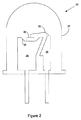
図2は、標準的なパッケージングにおける、本発明によるダイオードを組み込んだランプの断面図である。ランプ全体を32で示すが、その中にふくまれる要素は、当業者には周知なものである。実際、ここに開示するダイオードの利点の1つは、そのサイズ及び配向により、標準的なパッケージングで実装することができ、これに伴う便益が製造業者及び最終ユーザに得られることである。 FIG. 2 is a cross-sectional view of a lamp incorporating a diode according to the present invention in standard packaging. The entire lamp is shown at 32, but the elements contained therein are well known to those skilled in the art. In fact, one of the advantages of the disclosed diode is that, due to its size and orientation, it can be implemented in standard packaging, with the benefits associated with it for manufacturers and end users.
ランプ32はダイオードを含み、該ダイオードは、ここでも20で示されている。ダイオードは、反射カップ33内に配置されており、図2に示す形式のダイオードでは、これをアンビル(anvil)34と呼ぶこともあり、更に、ランプ32への電気コンタクトの一方を形成する。アンビルは、導電性があり、通常、金属で形成されている。明確化のために、図2では、ダイオード20がダイ・カップ33の中に位置するように示しているが、実際には、導電性の接着剤又ははんだ(図示せず)によって、適所に固定されている。アンビル34は、ダイオード20の背面オーミック・コンタクト30(図1)と電気的に接触しており、上位ボンド・ワイヤ35がダイオード20の上面オーミック・コンタクト28(これも図1にある)と電気的に接触している。勿論、背面支持部27及びオーミック・コンタクト30を省略する場合、アンビル34は、はんだ層26又はバリア金属層25と直接接触する。一方、上位ボンド・ワイヤ35は、ポストと呼ばれる、更に大きな別の電極36に接続する。パッケージ全体は、ポリマ筐体又はレンズ37を含み、そのサイズ及び形状は、材料と共に、特定の出力に合わせて選択される。
The
図2には詳細に示していないが、図2に示したデバイス20では、アクティブ層22、23は、ダイ・カップ33の底面(floor)に隣接しており、炭化珪素基板21がカップから離れて、上向きで面している。
図2は、一例のある程度模式的な図であり、非常に類似したパッケージにより、表面実装、金属缶(metal can)、又は金属ヘッダ、さらには図2に示すエポキシ・レンズを包含することもできる。
Although not shown in detail in FIG. 2, in
FIG. 2 is an example of a somewhat schematic diagram that can include surface mounts, metal cans, or metal headers, and even the epoxy lens shown in FIG. 2, with very similar packages. .
本発明は、限定するものではないが、5mmパッケージにおける使用が可能であり、5mmパッケージ(T−13/4型としても知られている)は、周知であり、広く入手可能であり、当業界において頻繁に用いられている。したがって、これは、本発明の封入及び使用に関して、本発明の適用可能な形態を表している。
これらの側面を背景として、本発明の性能面を関連付けて表すことができる。つまり、第1実施形態では、本発明は、単位面積当たりの出力に利点がある発光ダイオードはであり、面積が10,000μ2、順方向電圧が4.0ボルト未満、20ミリアンペアの駆動電流における放射束が少なくとも24ミリワット、そして主波長が約395〜540nmの間である。
The present invention is not limited, but can be used in a 5 mm package, and the 5 mm package (also known as the T-13 / 4 type) is well known and widely available in the industry. Frequently used. This therefore represents an applicable form of the invention with respect to the encapsulation and use of the invention.
With these aspects as the background, the performance aspects of the present invention can be related to each other. That is, in the first embodiment, the present invention is a light-emitting diode that has an advantage in output per unit area, with an area of 10,000 μ 2 , a forward voltage of less than 4.0 volts, and a drive current of 20 mA. The radiant flux is at least 24 milliwatts and the dominant wavelength is between about 395 and 540 nm.
半導体技術においては周知であるが、順方向電圧(Vf)は、所与の電流における電圧であると定義されている。一般的に言うと、小規模(微小)な用途において用いられるダイオードでは、特にここに明記する明度レベルでは、順方向電圧が低い方が有利であると言える。好適な実施形態では、本発明によるダイオードは、4.0ボルトの順方向電圧、又は少なくとも20ミリアンペアの駆動電流で動作することができる。 As is well known in semiconductor technology, the forward voltage (V f ) is defined as the voltage at a given current. Generally speaking, for diodes used in small (small) applications, a lower forward voltage is advantageous, especially at the lightness levels specified here. In a preferred embodiment, a diode according to the present invention can operate with a forward voltage of 4.0 volts, or a drive current of at least 20 milliamps.
放射束を測定するには、T1−3/4型の封入ランプを、分光計に取り付けた積分球(integrating sphere)内に配置する。測定デバイスの一例に、可視LED用のLabsphere Omni LTS分光計がある。放射束は、電力(ワット)単位で測定する。
当技術分野(そして本明細書)において用いる場合、「主波長」という用語は、発光ダイオードによって人間の目において生ずる色相の飽和の尺度を表している。主波長を判定するには、基準光源の色座標、及び国際照明委員会(CIE)1931色度図におけるLEDの測定色度座標上で直線を引く。色度図の境界上における直線の交点が、主波長を示す。
To measure the radiant flux, a T1-3 / 4 type enclosed lamp is placed in an integrating sphere attached to the spectrometer. An example of a measuring device is a Labsphere Omni LTS spectrometer for visible LEDs. Radiant flux is measured in power (watts).
As used in the art (and herein), the term “dominant wavelength” represents a measure of hue saturation that occurs in the human eye by light emitting diodes. To determine the dominant wavelength, a straight line is drawn on the color coordinates of the reference light source and the measured chromaticity coordinates of the LEDs in the International Illumination Commission (CIE) 1931 chromaticity diagram. The intersection of the straight lines on the boundary of the chromaticity diagram indicates the dominant wavelength.
ピーク波長とは、最大スペクトル・パワーにおける波長である。ピーク波長は、実用的な目的では、重要性が低い場合がある。何故なら、2つの異なる発光ダイオードが同じピーク座標を有していても、色の認知度が異なる場合があるからである。
発光ダイオードのこれら及び他の光学特性に関するしかるべき論述が、ニュー・ハンプシャー州North SuttonのLabsphere Inc.からのLabsphere Technical Guide, "The Radiometry of Light Emitting Diodes"(発光ダイオードの放射測定)に明記されている。
The peak wavelength is the wavelength at maximum spectral power. The peak wavelength may be less important for practical purposes. This is because even when two different light emitting diodes have the same peak coordinates, color recognition may be different.
The appropriate discussion of these and other optical properties of light emitting diodes is specified in the Labsphere Technical Guide, "The Radiometry of Light Emitting Diodes" from Labsphere Inc., North Sutton, New Hampshire. Yes.
レンズ37は、光線の方向及び分布(即ち、空間分布パターン)を変化させるために用いられ、一部の発光ダイオードのためには、光学フィルタとして供するように着色されている。本発明によるダイオードは、白色光の生成に関連して頻繁に用いられるので、着色レンズの使用はさほど広く行われてはいない。
The
発光ダイオードの放射束を測定するには、通常、積分球を用いる。これには、先に引用したデバイスが全面的に適しているが、これに限定されるのではない。
放射束は、放射パワーとも呼ばれ、放射場(radiation field)が放射エネルギを1つの領域から他の領域に伝達する速度(dθ/dt)である。先に注記したように、シータ(θ)を放射エネルギとすると、放射パワーの単位はワットである。
An integrating sphere is usually used to measure the radiant flux of a light emitting diode. For this, the above-cited device is perfectly suitable, but is not limited thereto.
Radiant flux, also called radiant power, is the rate (dθ / dt) at which a radiation field transmits radiant energy from one region to another. As noted above, where theta (θ) is radiant energy, the unit of radiant power is watts.
本発明によるダイオードの主波長は、通例、約395nm〜540nmの間であり、電磁スペクトルの緑、青、紫、及び紫外部分に該当する。更に特定すれば、本発明によるダイオードの主波長は、約450〜480nmの間であり、好ましい出力波長は約455〜465nmの間である。これにより、その出力は可視光スペクトルの青色部分にすっぽりと納まることになり、ディスプレイや関連する目的のための全色及び白色に関して、多数の利点が得られる。 The dominant wavelength of the diode according to the invention is typically between about 395 nm and 540 nm, corresponding to the green, blue, purple and ultraviolet parts of the electromagnetic spectrum. More particularly, the dominant wavelength of the diode according to the present invention is between about 450-480 nm and the preferred output wavelength is between about 455-465 nm. This allows the output to fit entirely in the blue portion of the visible light spectrum, providing a number of advantages over all colors and white for display and related purposes.
本発明によるダイオードは、20ミリアンペアの駆動電流において、少なくとも24ミリワットの放射束を有することができる。これは、全て種類の発光ダイオードの性能を測定する際における典型的な標準であり、したがって、本発明によるダイオードに対して有用な比較を行うことができる。 The diode according to the invention can have a radiant flux of at least 24 milliwatts at a drive current of 20 milliamps. This is a typical standard in measuring the performance of all types of light emitting diodes, and therefore a useful comparison can be made for the diodes according to the invention.
本発明による青色発光ダイオードは、画素に組み込むことができ、特に他の原色(赤及び緑)を形成するものと組み合わせて、全色ディスプレイを提供することができる。
他の態様では、本発明による発光ダイオードは、主波長が約395〜540nmの間、順方向電圧が4.0ボルト未満、そして駆動電流が20ミリアンペアとしたときに、1平方ミリメートル当たり少なくとも270ミリワットの放射束を生成する。
他の態様では、本発明は、単位面積当たりの有利な出力を有する発光ダイオードであり、面積が100,000μ2のダイ、ダイを封入するパッケージが5mm、順方向電圧が4.0ボルト未満、そして420〜465nmの間の波長及び20ミリアンペアの駆動電圧において外部量子効率(external quantum efficiency)が45%超である。
The blue light emitting diode according to the present invention can be incorporated into a pixel and can be combined with those forming other primary colors (red and green) in particular to provide a full color display.
In another aspect, the light emitting diode according to the present invention is at least 270 milliwatts per square millimeter when the dominant wavelength is between about 395 and 540 nm, the forward voltage is less than 4.0 volts, and the drive current is 20 milliamps. Produces a radiant flux of
In another aspect, the present invention is a light emitting diode having a favorable output per unit area, area 100,000Myu 2 die, package 5mm to enclose the die, it is a forward voltage of less than 4.0 volts, The external quantum efficiency is over 45% at a wavelength between 420 and 465 nm and a driving voltage of 20 milliamperes.
発光ダイオード及びそのパッケージに精通する者には分かるように、ダイオードを通過する注入電流によって発生する光子は、100%がダイオードの外部に漏出する。したがって、この技術分野では、「外部量子効率」という用語を用いて、放出光強度の電流に対する比率(例えば、出射する光子/入射する電子)を記述している。光子は、半導体材料自体の内部における吸収、光が半導体から空中に通過するときの屈折率の差による反射損失、そしてスネル(Snell)の法則によって規定される臨界角(critical angle)よりも大きな角度における光の全ての内部反射によって失われる可能性がある。したがって、パーセントで示す外部量子効率(EQE)は、放射束(ワット)、波長(ナノメートル)、駆動電流(アンペア)、そして以下の式による波長とエネルギ(λ=1.24/eV)間の変換係数から計算することができる。
EQE(%)=(放射束)×(波長)×100/{(1240)×(駆動電流)}
As will be appreciated by those familiar with light emitting diodes and their packages, 100% of the photons generated by the injected current passing through the diode will leak out of the diode. Therefore, in this technical field, the term “external quantum efficiency” is used to describe the ratio of emitted light intensity to current (eg, outgoing photons / incident electrons). Photons are absorbed inside the semiconductor material itself, reflection losses due to refractive index differences when light passes from the semiconductor into the air, and angles greater than the critical angle defined by Snell's law Can be lost by all internal reflections of light in Thus, the external quantum efficiency (EQE) in percent is the radiant flux (watts), wavelength (nanometers), drive current (amperes), and between wavelength and energy (λ = 1.24 / eV) according to It can be calculated from the conversion factor.
EQE (%) = (radiant flux) × (wavelength) × 100 / {(1240) × (driving current)}
したがって、別の態様では、本発明は、単位当たりで有利な出力を有する発光ダイオードとして記述することができ、5mmのポリマ・パッケージ、パッケージ内において100,000μ2未満の面積を占めるダイ、4.0ボルト未満の順方向電圧、20ミリアンペアの駆動電流において少なくとも24ミリワットの放射束、そして約395〜540nm間の主波長を備えている。
他の実施形態におけると同様、青色LEDでは、主波長は約450〜480nmの間が好ましく、約455〜465nmの間が最も好ましい。また、本発明によるダイオードは、約20ミリアンペアの駆動電圧で、少なくとも27ミリワットの放射束を得ることができた。
Thus, in another aspect, the invention can be described as a light emitting diode with advantageous output per unit, a 5 mm polymer package, a die that occupies an area less than 100,000 μ 2 within the package, It has a forward voltage of less than 0 volts, a radiant flux of at least 24 milliwatts at a drive current of 20 milliamps, and a dominant wavelength between about 395 and 540 nm.
As in the other embodiments, for blue LEDs, the dominant wavelength is preferably between about 450 and 480 nm, and most preferably between about 455 and 465 nm. The diode according to the present invention was able to obtain a radiant flux of at least 27 milliwatts at a driving voltage of about 20 milliamperes.
更に別の態様では、本発明の発光ダイオードは、導電性炭化珪素基板と、炭化珪素基板上にあるp型及びn型それぞれのIII族窒化物層と、炭化珪素基板及びIII族窒化物層に対して垂直方向に配向したオーミック・コンタクトと、基板、III族窒化物層、及びオーム・コンダクトの一部を封入するポリマ・パッケージと、20ミリアンペアの駆動電流で、パッケージの放出面1平方ミリメートル当たり約270ミリワットの放射束とを有している。 In yet another aspect, the light-emitting diode of the present invention includes a conductive silicon carbide substrate, p-type and n-type group III nitride layers on the silicon carbide substrate, and a silicon carbide substrate and group III nitride layer. Per-square millimeters of the package's emission surface with ohmic contacts oriented vertically to the substrate, a polymer package enclosing a portion of the substrate, III-nitride layer, and ohmic conduct, and a drive current of 20 milliamps A radiant flux of about 270 milliwatts.
典型的な実施形態では、ダイオードは、5mm又は表面実装パッケージであり、炭化珪素基板は、3C、4H、6H、及び15Rプロトタイプの炭化珪素から成る群から選択されたプロトタイプを有する。
ここで用いる場合、また発光出力を記述し定義する目的上、発光エリア又は表面をデバイスの「フットプリント」と定義する。異なる寸法を有する複数の部分を含むチップ又はダイについては、「エリア」という用語は、ダイ又はチップ内における半導体基板材料の最大エリアを意味する。何故なら、この最大のサイズは、回路又はデバイスの設計者が個々の発光ダイオードを用いる際に考慮しなければならないからである。
In an exemplary embodiment, the diode is a 5 mm or surface mount package and the silicon carbide substrate has a prototype selected from the group consisting of 3C, 4H, 6H, and 15R prototype silicon carbide.
As used herein, and for purposes of describing and defining light output, the light emitting area or surface is defined as the “footprint” of the device. For a chip or die that includes multiple portions having different dimensions, the term “area” means the largest area of semiconductor substrate material within the die or chip. This is because this maximum size must be considered by circuit or device designers when using individual light emitting diodes.
図6は、この点を示す、従来技術のダイオードの平面模式図である。図6において、ダイオード全体を一括して40で示し、サファイア(Al2O3)基板41を含む。サファイアは、その総合的に堅牢な物理的特性と優れた光学的固有性のために、多数種類の発光ダイオードにおいて基板として用いられている。その結晶格子も、必ずしも最適ではないが、要求を満たしており、青色発光ダイオードを形成する際に通常用いられるIII族窒化物の結晶格子と一致する。しかしながら、サファイアは、ドーピングによって導電性にすることができず、常に電気絶縁体として機能する。その結果、サファイアを基板として選択する場合、図6に示すような構造を必然的に採用しなければならなくなる。すなわち、アクティブ層をサファイア基板41上に形成し、電流注入のためのp−n接合部を形成する。アクティブ層の内2つを42及び43で示す。しかしながら、サファイア基板41は絶縁性であるので、2つのワイヤ・ボンド・パッド44及び45が、図6に示すように、デバイスの上面に向かい合わなければならない。このため、ここで用いる定義に合わせるには、ダイオード40のエリア(単位面積当たりの出力を測定し表現する目的上)は、単にアクティブ層42又は小さい方のアクティブ層43のエリアではなく、サファイア基板のエリアとなる。
FIG. 6 is a schematic plan view of a prior art diode showing this point. In FIG. 6, the entire diode is collectively indicated by 40 and includes a sapphire (Al 2 O 3 )
意味は同じであるが別の表現では、このエリアは、(i)ダイオードの最大の半導体エリア、又は(ii)封入されなければならない、又はされることになるダイオードの基板エリアのいずれかよりも大きい。殆ど全ての状況において、エリア(ii)はエリア(i)以上となる。 In another representation, although the meaning is the same, this area is more than either (i) the largest semiconductor area of the diode, or (ii) the substrate area of the diode that must or will be encapsulated. large. In almost all situations, area (ii) is greater than or equal to area (i).
図3、図4、及び図5は、本発明による性能出力特性を有する実施形態の更に別の構造を示す。
図3において、ダイオード全体を50で示し、フリップ・チップ配向で示す。即ち、ダイオード50を表面実装すると、炭化珪素基板51が最上位即ち上側となる配置になる。基板51は、傾斜面52を有し、全内反射を減少させることにより、デバイスから出力される光を増大させることができる。
3, 4 and 5 show yet another structure of an embodiment having performance output characteristics according to the present invention.
In FIG. 3, the entire diode is indicated by 50 and in flip chip orientation. That is, when the
簡略化の主旨により、アクティブ層は単一層53として示されているが、アクティブ構造は、通常、少なくとも1つのp型及び1つのn型層を含み、量子ウェル、多数の量子ウェル、及び超格子構造というような、図よりも精巧な構造を含むことは言うまでもない。多数のこのようなダイオードにおけると同様、ダイオード50は、ミラー層54を含むことが好ましく、ミラー層54が銀で形成される場合、図1に関して先に論じたようにして、部分的に絶縁することが好ましい。銀よりも反応性が低い金属で形成する場合、又は拡散(migrate)する可能性が低い場合、ミラー層54は、図3に示すような単純なコーティングとすることができる。図3では、ミラー層54は、オーミック・コンタクトも形成する。
ダイオード50への電気的接触は、デバイスの底面(図示の配向において)にある接合金属コンタクト55を通じて、そして上面におけるワイヤ・ボンド・パッド56に対して行われる。
For the sake of simplicity, the active layer is shown as a
Electrical contact to the
図4は、ほぼ図3と同様であり、全体を60と付番したダイオードを示す。図4のダイオード60と図3のダイオード50との間において関係のある唯一の相違は、デバイス60の上面に対して垂直又はほぼ垂直な側壁62の形状にある。図4では、形状が多少異なる基板に61と付番するが、その他の要素は全て、構造及び機能上、図3における同一の要素とほぼ同一であり、したがって同じ参照番号を付する。つまり、アクティブ層には53と付番し、ミラー・コンタクトには54、上面オーミック・コンタクトには56、そして接合金属には55と付番する。
FIG. 4 is substantially similar to FIG. 3 and shows a diode numbered 60 as a whole. The only difference relevant between the
図4には具体的に示していないが(他の図面にも)、ダイオード60の発光面、即ち、側縁62及び上面63は、レンズ形状又はパターンに形成することができ、ダイオードから抽出する光を増大するのを促進することができる。この主旨でレンズ状表面を用いることは、本願の親出願に明記されており、光抽出のために表面を変化させるその他の手段も、同様に、本願と譲受人を同じくする米国特許第6,791,119号に明記されている。その内容は、ここで引用したことにより本願にも含まれるものとする。
Although not specifically shown in FIG. 4 (also in other drawings), the light emitting surface, that is, the
図5は、本発明の別の実施形態を示し、ここでは、アクティブ層(複数のアクティブ層)66がデバイスの上面に位置し、オーミック・コンタクト67と直接接触している。ミラー・オーミック・コンタクト70は、光抽出を増大させるためにアクティブ層66の直下にあり、任意に、アクティブ層66及びミラー70を基板72に接着するために、金属接合層71が含まれる。基板72は、炭化珪素のような半導体、又は潜在的に導体とすることができる。基板72へのオーミック・コンタクト73により、デバイスが完成する。ミラー・コンタクト70が銀又は銀系である場合、バリア構造(例えば、図1に関して説明したようなバリア構造)も含まれる。
FIG. 5 illustrates another embodiment of the present invention, where the active layer (s) 66 is located on the top surface of the device and is in direct contact with the ohmic contact 67. The mirror
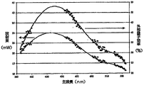
図7は、本発明による発光ダイオードについて、スペクトル放射束出力(mW、下側の曲線)、及び外部量子効率(%、上側の曲線)を組み合わせて示したグラフである。図に示すように、ダイオードの相対的光束は、波長によって異なる。したがって、本発明によるダイオードは、ある波長における性能に関して表現するが、個々のダイオードにとって最も好ましい波長における最大出力未満であっても、他の波長における対応する割合の出力も実現可能であり包含することは理解されるであろう。 FIG. 7 is a graph showing a combination of spectral radiant flux output (mW, lower curve) and external quantum efficiency (%, upper curve) for a light emitting diode according to the present invention. As shown in the figure, the relative luminous flux of the diode varies depending on the wavelength. Thus, the diode according to the present invention is expressed in terms of performance at one wavelength, but even if it is less than the maximum output at the wavelength most favorable for the individual diode, a corresponding percentage of output at other wavelengths is also feasible and encompassed Will be understood.
別の言い方をすると、所与の波長において単位面積当たりある出力を有するというここでの半導体の記述は、ここに記載又は特許請求するダイオードを、その波長における出力に限定するのではない。逆に、代数的曲線上にプロットした点と同様に、所与の波長における単位当たりの出力は、指示した単一点ではなく、曲線全体を示すものとする。 In other words, the description of a semiconductor herein having an output per unit area at a given wavelength does not limit the diode described or claimed herein to an output at that wavelength. Conversely, similar to the points plotted on the algebraic curve, the output per unit at a given wavelength shall represent the entire curve, not the single point indicated.
同様に、5mmパッケージにおけるダイオードの出力から、他の種類のパッケージからの出力に要求される精度も、同様に予測できる。したがって、この場合も同様に、5mmパッケージからの出力は、本発明すなわち請求項記載の発明を5mmパッケージに限定するのではなく、逆に、他の種類のパッケージにおいて、特許請求の範囲によってカバーされる出力を特定するために必要な情報を、当業者に提供するものである。 Similarly, the accuracy required for the output from other types of packages can be similarly predicted from the output of the diode in the 5 mm package. Therefore, in this case as well, the output from the 5 mm package is not limited to the present invention, ie, the claimed invention, to the 5 mm package, but conversely, in other types of packages, it is covered by the claims. The information necessary to specify the output to be provided is provided to those skilled in the art.
図面及び明細書において、本発明の好適な実施形態を明記し、特定的な用語を用いたが、これらは包括的及び記述的な意味で用いたに過ぎず、限定を主旨とするのではなく、本発明の範囲は特許請求の範囲に規定するものとする。 In the drawings and specification, preferred embodiments of the invention are specified and specific terms are used, but these are used in a comprehensive and descriptive sense only, not for the purpose of limitation. The scope of the present invention shall be defined in the claims.
Claims (40)
125,000平方ミクロン以下の面積と、
4.0ボルト未満の順方向電圧と、
20ミリアンペアの駆動電流において少なくとも27ミリワットの放射束と、
約395〜540ナノメートルの間の主波長と
を備えていることを特徴とする発光ダイオード。 A light emitting diode having an advantageous output per unit area,
An area of 125,000 square microns or less;
A forward voltage less than 4.0 volts;
A radiant flux of at least 27 milliwatts at a drive current of 20 milliamps;
A light emitting diode having a dominant wavelength between about 395 and 540 nanometers.
100,000平方ミクロン以下の面積と、
20ミリアンペアの駆動電流において少なくとも24ミリワットの放射束と
を有していることを特徴とする発光ダイオード。 The light emitting diode according to claim 1, wherein the light emitting diode comprises:
An area of 100,000 square microns or less;
A light emitting diode having a radiant flux of at least 24 milliwatts at a drive current of 20 milliamps.
100,000μ2未満の面積を有するダイと、
前記ダイを封入する5mmパッケージと、
約420〜465nmの間の波長及び20ミリアンペアの駆動電流において、45%よりも大きな外部量子効率と
を有していることを特徴とする発光ダイオード。 The light-emitting diode according to claim 1,
A die having an area of less than 100,000 μ 2 ;
A 5 mm package enclosing the die;
A light emitting diode having an external quantum efficiency of greater than 45% at a wavelength between about 420-465 nm and a drive current of 20 milliamps.
5mm(T1-3/4)ポリマ・パッケージと、
前記パッケージ内にあり、面積が100,000平方ミクロン未満のダイと
を備えていることを特徴とする発光ダイオード。 The light emitting diode according to claim 2, wherein
5mm (T1-3 / 4) polymer package,
A light emitting diode comprising a die within the package and having an area of less than 100,000 square microns.
約395〜540nm間の主波長、4.0ボルト未満の順方向電圧、及び20ミリアンペアの駆動電流において、1平方ミリメートル当たり少なくとも270ミリワットの単位面積放射束
を有していることを特徴とする発光ダイオード。 A light emitting diode having an advantageous output per unit area,
Emission having a unit area radiant flux of at least 270 milliwatts per square millimeter at a dominant wavelength between about 395 and 540 nm, a forward voltage of less than 4.0 volts, and a driving current of 20 milliamps diode.
導電性炭化珪素基板と、
前記炭化珪素基板上にあり、該基板と共にダイを規定する、p型及びn型それぞれのIII族窒化物層と、
前記炭化珪素基板及び前記III族窒化物層に対して垂直に配向されているオーミック・コンタクトと、
455〜465nmの間の主波長と、
前記基板、前記III族窒化物層、及び前記オーミック・コンタクトの一部を封入するポリマ・パッケージと、
を備えていることを特徴とする発光ダイオード。 The light emitting diode of claim 23,
A conductive silicon carbide substrate;
Each p-type and n-type group III nitride layer on the silicon carbide substrate and defining a die with the substrate;
Ohmic contacts oriented perpendicular to the silicon carbide substrate and the III-nitride layer;
A dominant wavelength between 455 and 465 nm;
A polymer package encapsulating the substrate, the III-nitride layer, and a portion of the ohmic contact;
A light-emitting diode comprising:
Applications Claiming Priority (3)
| Application Number | Priority Date | Filing Date | Title |
|---|---|---|---|
| US10/951,042 US7259402B2 (en) | 2004-09-22 | 2004-09-22 | High efficiency group III nitride-silicon carbide light emitting diode |
| US11/037,965 US8513686B2 (en) | 2004-09-22 | 2005-01-18 | High output small area group III nitride LEDs |
| PCT/US2005/033013 WO2006036582A1 (en) | 2004-09-22 | 2005-09-15 | High output small area group iii nitride leds |
Publications (2)
| Publication Number | Publication Date |
|---|---|
| JP2008514030A true JP2008514030A (en) | 2008-05-01 |
| JP2008514030A5 JP2008514030A5 (en) | 2012-01-19 |
Family
ID=35601712
Family Applications (1)
| Application Number | Title | Priority Date | Filing Date |
|---|---|---|---|
| JP2007533549A Pending JP2008514030A (en) | 2004-09-22 | 2005-09-15 | High power small area III-nitride LED |
Country Status (6)
| Country | Link |
|---|---|
| US (1) | US8513686B2 (en) |
| EP (1) | EP1792353B1 (en) |
| JP (1) | JP2008514030A (en) |
| KR (2) | KR20070046182A (en) |
| TW (1) | TWI312584B (en) |
| WO (1) | WO2006036582A1 (en) |
Cited By (8)
| Publication number | Priority date | Publication date | Assignee | Title |
|---|---|---|---|---|
| JP2010153814A (en) * | 2008-12-24 | 2010-07-08 | Seoul Opto Devices Co Ltd | Light-emitting device having plurality of light-emitting cells and method of fabricating the same |
| US8487337B2 (en) | 2006-04-24 | 2013-07-16 | Cree, Inc. | Side view surface mount LED |
| US8617909B2 (en) | 2004-07-02 | 2013-12-31 | Cree, Inc. | LED with substrate modifications for enhanced light extraction and method of making same |
| US8858004B2 (en) | 2005-12-22 | 2014-10-14 | Cree, Inc. | Lighting device |
| US8901585B2 (en) | 2003-05-01 | 2014-12-02 | Cree, Inc. | Multiple component solid state white light |
| US9431589B2 (en) | 2007-12-14 | 2016-08-30 | Cree, Inc. | Textured encapsulant surface in LED packages |
| US9666772B2 (en) | 2003-04-30 | 2017-05-30 | Cree, Inc. | High powered light emitter packages with compact optics |
| US10615324B2 (en) | 2013-06-14 | 2020-04-07 | Cree Huizhou Solid State Lighting Company Limited | Tiny 6 pin side view surface mount LED |
Families Citing this family (33)
| Publication number | Priority date | Publication date | Assignee | Title |
|---|---|---|---|---|
| US7915085B2 (en) * | 2003-09-18 | 2011-03-29 | Cree, Inc. | Molded chip fabrication method |
| WO2007035333A1 (en) * | 2005-09-16 | 2007-03-29 | Cree, Inc. | Methods of processing semiconductor wafers having silicon carbide power devices thereon |
| US7846391B2 (en) | 2006-05-22 | 2010-12-07 | Lumencor, Inc. | Bioanalytical instrumentation using a light source subsystem |
| US7910945B2 (en) * | 2006-06-30 | 2011-03-22 | Cree, Inc. | Nickel tin bonding system with barrier layer for semiconductor wafers and devices |
| US8643195B2 (en) | 2006-06-30 | 2014-02-04 | Cree, Inc. | Nickel tin bonding system for semiconductor wafers and devices |
| US20080042145A1 (en) * | 2006-08-18 | 2008-02-21 | Helmut Hagleitner | Diffusion barrier for light emitting diodes |
| US7910938B2 (en) | 2006-09-01 | 2011-03-22 | Cree, Inc. | Encapsulant profile for light emitting diodes |
| US8425271B2 (en) | 2006-09-01 | 2013-04-23 | Cree, Inc. | Phosphor position in light emitting diodes |
| US7855459B2 (en) | 2006-09-22 | 2010-12-21 | Cree, Inc. | Modified gold-tin system with increased melting temperature for wafer bonding |
| TWI533351B (en) * | 2006-12-11 | 2016-05-11 | 美國加利福尼亞大學董事會 | Metalorganic chemical vapor deposition (mocvd) growth of high performance non-polar iii-nitride optical devices |
| US9178121B2 (en) * | 2006-12-15 | 2015-11-03 | Cree, Inc. | Reflective mounting substrates for light emitting diodes |
| US9024349B2 (en) | 2007-01-22 | 2015-05-05 | Cree, Inc. | Wafer level phosphor coating method and devices fabricated utilizing method |
| US9159888B2 (en) * | 2007-01-22 | 2015-10-13 | Cree, Inc. | Wafer level phosphor coating method and devices fabricated utilizing method |
| US7709811B2 (en) * | 2007-07-03 | 2010-05-04 | Conner Arlie R | Light emitting diode illumination system |
| US8098375B2 (en) | 2007-08-06 | 2012-01-17 | Lumencor, Inc. | Light emitting diode illumination system |
| DE102007046519A1 (en) * | 2007-09-28 | 2009-04-02 | Osram Opto Semiconductors Gmbh | Thin-film LED with a mirror layer and method for its production |
| US9041285B2 (en) | 2007-12-14 | 2015-05-26 | Cree, Inc. | Phosphor distribution in LED lamps using centrifugal force |
| TWI413453B (en) * | 2008-11-20 | 2013-10-21 | Epistar Corp | Alternating current light emitting diode device |
| US8878219B2 (en) * | 2008-01-11 | 2014-11-04 | Cree, Inc. | Flip-chip phosphor coating method and devices fabricated utilizing method |
| US8242462B2 (en) | 2009-01-23 | 2012-08-14 | Lumencor, Inc. | Lighting design of high quality biomedical devices |
| US10546846B2 (en) | 2010-07-23 | 2020-01-28 | Cree, Inc. | Light transmission control for masking appearance of solid state light sources |
| US8362458B2 (en) * | 2010-12-27 | 2013-01-29 | Industrial Technology Research Institute | Nitirde semiconductor light emitting diode |
| US8389957B2 (en) | 2011-01-14 | 2013-03-05 | Lumencor, Inc. | System and method for metered dosage illumination in a bioanalysis or other system |
| US8466436B2 (en) | 2011-01-14 | 2013-06-18 | Lumencor, Inc. | System and method for metered dosage illumination in a bioanalysis or other system |
| US9166126B2 (en) | 2011-01-31 | 2015-10-20 | Cree, Inc. | Conformally coated light emitting devices and methods for providing the same |
| US9642515B2 (en) | 2012-01-20 | 2017-05-09 | Lumencor, Inc. | Solid state continuous white light source |
| US9217561B2 (en) | 2012-06-15 | 2015-12-22 | Lumencor, Inc. | Solid state light source for photocuring |
| US10971612B2 (en) | 2019-06-13 | 2021-04-06 | Cree, Inc. | High electron mobility transistors and power amplifiers including said transistors having improved performance and reliability |
| US10923585B2 (en) | 2019-06-13 | 2021-02-16 | Cree, Inc. | High electron mobility transistors having improved contact spacing and/or improved contact vias |
| US11769768B2 (en) | 2020-06-01 | 2023-09-26 | Wolfspeed, Inc. | Methods for pillar connection on frontside and passive device integration on backside of die |
| US20220376085A1 (en) | 2021-05-20 | 2022-11-24 | Cree, Inc. | Methods of manufacturing high electron mobility transistors having improved performance |
| US11842937B2 (en) | 2021-07-30 | 2023-12-12 | Wolfspeed, Inc. | Encapsulation stack for improved humidity performance and related fabrication methods |
| US20230078017A1 (en) | 2021-09-16 | 2023-03-16 | Wolfspeed, Inc. | Semiconductor device incorporating a substrate recess |
Citations (2)
| Publication number | Priority date | Publication date | Assignee | Title |
|---|---|---|---|---|
| WO2004010509A2 (en) * | 2002-07-22 | 2004-01-29 | Cree, Inc. | Light emitting diode including barrier layers and manufacturing methods therefor |
| JP2004521494A (en) * | 2001-02-01 | 2004-07-15 | クリー インコーポレイテッド | Light emitting diode with improved light extraction and method of manufacturing the same |
Family Cites Families (59)
| Publication number | Priority date | Publication date | Assignee | Title |
|---|---|---|---|---|
| US465809A (en) * | 1891-12-22 | Electrical testing-instrument | ||
| US2001622A (en) * | 1930-10-27 | 1935-05-14 | David G Mccaa | Method of and means for reducing electrical disturbances |
| FR2554606B1 (en) * | 1983-11-04 | 1987-04-10 | Thomson Csf | OPTICAL DEVICE FOR CONCENTRATION OF LIGHT RADIATION EMITTED BY A LIGHT EMITTING DIODE, AND LIGHT EMITTING DIODE COMPRISING SUCH A DEVICE |
| JPS6159886A (en) | 1984-08-31 | 1986-03-27 | Fujitsu Ltd | Manufacture of photosemiconductor device |
| JPH0770755B2 (en) * | 1988-01-21 | 1995-07-31 | 三菱化学株式会社 | High brightness LED epitaxial substrate and method of manufacturing the same |
| US4912532A (en) * | 1988-08-26 | 1990-03-27 | Hewlett-Packard Company | Electro-optical device with inverted transparent substrate and method for making same |
| US5103271A (en) * | 1989-09-28 | 1992-04-07 | Kabushiki Kaisha Toshiba | Semiconductor light emitting device and method of fabricating the same |
| US5300788A (en) * | 1991-01-18 | 1994-04-05 | Kopin Corporation | Light emitting diode bars and arrays and method of making same |
| US5376580A (en) * | 1993-03-19 | 1994-12-27 | Hewlett-Packard Company | Wafer bonding of light emitting diode layers |
| US5416342A (en) * | 1993-06-23 | 1995-05-16 | Cree Research, Inc. | Blue light-emitting diode with high external quantum efficiency |
| US5592501A (en) * | 1994-09-20 | 1997-01-07 | Cree Research, Inc. | Low-strain laser structures with group III nitride active layers |
| US5631190A (en) * | 1994-10-07 | 1997-05-20 | Cree Research, Inc. | Method for producing high efficiency light-emitting diodes and resulting diode structures |
| US5739554A (en) * | 1995-05-08 | 1998-04-14 | Cree Research, Inc. | Double heterojunction light emitting diode with gallium nitride active layer |
| US5985687A (en) * | 1996-04-12 | 1999-11-16 | The Regents Of The University Of California | Method for making cleaved facets for lasers fabricated with gallium nitride and other noncubic materials |
| DE19640594B4 (en) * | 1996-10-01 | 2016-08-04 | Osram Gmbh | module |
| US6825501B2 (en) * | 1997-08-29 | 2004-11-30 | Cree, Inc. | Robust Group III light emitting diode for high reliability in standard packaging applications |
| TW393785B (en) * | 1997-09-19 | 2000-06-11 | Siemens Ag | Method to produce many semiconductor-bodies |
| US6201262B1 (en) * | 1997-10-07 | 2001-03-13 | Cree, Inc. | Group III nitride photonic devices on silicon carbide substrates with conductive buffer interlay structure |
| US6071795A (en) * | 1998-01-23 | 2000-06-06 | The Regents Of The University Of California | Separation of thin films from transparent substrates by selective optical processing |
| JPH11238913A (en) | 1998-02-20 | 1999-08-31 | Namiki Precision Jewel Co Ltd | Semiconductor light-emitting device chip |
| US6459100B1 (en) * | 1998-09-16 | 2002-10-01 | Cree, Inc. | Vertical geometry ingan LED |
| JP3525061B2 (en) * | 1998-09-25 | 2004-05-10 | 株式会社東芝 | Method for manufacturing semiconductor light emitting device |
| US6744800B1 (en) * | 1998-12-30 | 2004-06-01 | Xerox Corporation | Method and structure for nitride based laser diode arrays on an insulating substrate |
| US20010042866A1 (en) * | 1999-02-05 | 2001-11-22 | Carrie Carter Coman | Inxalygazn optical emitters fabricated via substrate removal |
| US6320206B1 (en) * | 1999-02-05 | 2001-11-20 | Lumileds Lighting, U.S., Llc | Light emitting devices having wafer bonded aluminum gallium indium nitride structures and mirror stacks |
| US6258699B1 (en) * | 1999-05-10 | 2001-07-10 | Visual Photonics Epitaxy Co., Ltd. | Light emitting diode with a permanent subtrate of transparent glass or quartz and the method for manufacturing the same |
| DE60042187D1 (en) * | 1999-06-09 | 2009-06-25 | Toshiba Kawasaki Kk | Bond-type semiconductor substrate, semiconductor light-emitting device, and manufacturing method |
| US6812053B1 (en) * | 1999-10-14 | 2004-11-02 | Cree, Inc. | Single step pendeo- and lateral epitaxial overgrowth of Group III-nitride epitaxial layers with Group III-nitride buffer layer and resulting structures |
| US6410942B1 (en) * | 1999-12-03 | 2002-06-25 | Cree Lighting Company | Enhanced light extraction through the use of micro-LED arrays |
| JP5965095B2 (en) * | 1999-12-03 | 2016-08-10 | クリー インコーポレイテッドCree Inc. | Light-emitting diode with improved light extraction by internal and external optical elements |
| US20020068373A1 (en) * | 2000-02-16 | 2002-06-06 | Nova Crystals, Inc. | Method for fabricating light emitting diodes |
| DE10008583A1 (en) * | 2000-02-24 | 2001-09-13 | Osram Opto Semiconductors Gmbh | Production of an optically transparent substrate comprises epitaxially growing a substrate layer on a substrate, connecting the substrate layer to the side with an optically transparent layer, and removing the substrate |
| US6335263B1 (en) * | 2000-03-22 | 2002-01-01 | The Regents Of The University Of California | Method of forming a low temperature metal bond for use in the transfer of bulk and thin film materials |
| JP4060511B2 (en) * | 2000-03-28 | 2008-03-12 | パイオニア株式会社 | Method for separating nitride semiconductor device |
| DE10051465A1 (en) * | 2000-10-17 | 2002-05-02 | Osram Opto Semiconductors Gmbh | Method for producing a GaN-based semiconductor component |
| US6410940B1 (en) * | 2000-06-15 | 2002-06-25 | Kansas State University Research Foundation | Micro-size LED and detector arrays for minidisplay, hyper-bright light emitting diodes, lighting, and UV detector and imaging sensor applications |
| DE10033496A1 (en) * | 2000-07-10 | 2002-01-31 | Osram Opto Semiconductors Gmbh | Semiconductor chip for optoelectronics |
| US6562648B1 (en) * | 2000-08-23 | 2003-05-13 | Xerox Corporation | Structure and method for separation and transfer of semiconductor thin films onto dissimilar substrate materials |
| DE10042947A1 (en) * | 2000-08-31 | 2002-03-21 | Osram Opto Semiconductors Gmbh | Radiation-emitting semiconductor component based on GaN |
| JP4091261B2 (en) * | 2000-10-31 | 2008-05-28 | 株式会社東芝 | Semiconductor light emitting device and manufacturing method thereof |
| US6800876B2 (en) * | 2001-01-16 | 2004-10-05 | Cree, Inc. | Group III nitride LED with undoped cladding layer (5000.137) |
| US6468824B2 (en) * | 2001-03-22 | 2002-10-22 | Uni Light Technology Inc. | Method for forming a semiconductor device having a metallic substrate |
| US6946788B2 (en) | 2001-05-29 | 2005-09-20 | Toyoda Gosei Co., Ltd. | Light-emitting element |
| JP2002368263A (en) * | 2001-06-06 | 2002-12-20 | Toyoda Gosei Co Ltd | Iii nitride compound semiconductor light-emitting device |
| CN1505843B (en) * | 2001-06-15 | 2010-05-05 | 克里公司 | GaN based LED formed on a SiC substrate |
| US6888167B2 (en) * | 2001-07-23 | 2005-05-03 | Cree, Inc. | Flip-chip bonding of light emitting devices and light emitting devices suitable for flip-chip bonding |
| US6740906B2 (en) * | 2001-07-23 | 2004-05-25 | Cree, Inc. | Light emitting diodes including modifications for submount bonding |
| US6747298B2 (en) * | 2001-07-23 | 2004-06-08 | Cree, Inc. | Collets for bonding of light emitting diodes having shaped substrates |
| US6924596B2 (en) * | 2001-11-01 | 2005-08-02 | Nichia Corporation | Light emitting apparatus provided with fluorescent substance and semiconductor light emitting device, and method of manufacturing the same |
| US6635503B2 (en) * | 2002-01-28 | 2003-10-21 | Cree, Inc. | Cluster packaging of light emitting diodes |
| US6716654B2 (en) * | 2002-03-12 | 2004-04-06 | Opto Tech Corporation | Light-emitting diode with enhanced brightness and method for fabricating the same |
| US20040012027A1 (en) * | 2002-06-13 | 2004-01-22 | Cree Lighting Company | Saturated phosphor solid state emitter |
| US6649437B1 (en) * | 2002-08-20 | 2003-11-18 | United Epitaxy Company, Ltd. | Method of manufacturing high-power light emitting diodes |
| US6917057B2 (en) * | 2002-12-31 | 2005-07-12 | Gelcore Llc | Layered phosphor coatings for LED devices |
| US6825559B2 (en) * | 2003-01-02 | 2004-11-30 | Cree, Inc. | Group III nitride based flip-chip intergrated circuit and method for fabricating |
| TWI226138B (en) * | 2003-01-03 | 2005-01-01 | Super Nova Optoelectronics Cor | GaN-based LED vertical device structure and the manufacturing method thereof |
| US6786390B2 (en) * | 2003-02-04 | 2004-09-07 | United Epitaxy Company Ltd. | LED stack manufacturing method and its structure thereof |
| US6806112B1 (en) * | 2003-09-22 | 2004-10-19 | National Chung-Hsing University | High brightness light emitting diode |
| KR100609117B1 (en) * | 2005-05-03 | 2006-08-08 | 삼성전기주식회사 | Nitride semiconductor light emitting device and method of manufacturing the same |
-
2005
- 2005-01-18 US US11/037,965 patent/US8513686B2/en active Active
- 2005-09-15 JP JP2007533549A patent/JP2008514030A/en active Pending
- 2005-09-15 WO PCT/US2005/033013 patent/WO2006036582A1/en active Application Filing
- 2005-09-15 TW TW094131892A patent/TWI312584B/en active
- 2005-09-15 KR KR1020077006473A patent/KR20070046182A/en active Search and Examination
- 2005-09-15 KR KR1020097017902A patent/KR20090099593A/en active Search and Examination
- 2005-09-15 EP EP05812300.1A patent/EP1792353B1/en active Active
Patent Citations (2)
| Publication number | Priority date | Publication date | Assignee | Title |
|---|---|---|---|---|
| JP2004521494A (en) * | 2001-02-01 | 2004-07-15 | クリー インコーポレイテッド | Light emitting diode with improved light extraction and method of manufacturing the same |
| WO2004010509A2 (en) * | 2002-07-22 | 2004-01-29 | Cree, Inc. | Light emitting diode including barrier layers and manufacturing methods therefor |
Cited By (8)
| Publication number | Priority date | Publication date | Assignee | Title |
|---|---|---|---|---|
| US9666772B2 (en) | 2003-04-30 | 2017-05-30 | Cree, Inc. | High powered light emitter packages with compact optics |
| US8901585B2 (en) | 2003-05-01 | 2014-12-02 | Cree, Inc. | Multiple component solid state white light |
| US8617909B2 (en) | 2004-07-02 | 2013-12-31 | Cree, Inc. | LED with substrate modifications for enhanced light extraction and method of making same |
| US8858004B2 (en) | 2005-12-22 | 2014-10-14 | Cree, Inc. | Lighting device |
| US8487337B2 (en) | 2006-04-24 | 2013-07-16 | Cree, Inc. | Side view surface mount LED |
| US9431589B2 (en) | 2007-12-14 | 2016-08-30 | Cree, Inc. | Textured encapsulant surface in LED packages |
| JP2010153814A (en) * | 2008-12-24 | 2010-07-08 | Seoul Opto Devices Co Ltd | Light-emitting device having plurality of light-emitting cells and method of fabricating the same |
| US10615324B2 (en) | 2013-06-14 | 2020-04-07 | Cree Huizhou Solid State Lighting Company Limited | Tiny 6 pin side view surface mount LED |
Also Published As
| Publication number | Publication date |
|---|---|
| WO2006036582A1 (en) | 2006-04-06 |
| EP1792353A1 (en) | 2007-06-06 |
| KR20090099593A (en) | 2009-09-22 |
| US20060060879A1 (en) | 2006-03-23 |
| TWI312584B (en) | 2009-07-21 |
| TW200625690A (en) | 2006-07-16 |
| US8513686B2 (en) | 2013-08-20 |
| KR20070046182A (en) | 2007-05-02 |
| EP1792353B1 (en) | 2020-03-11 |
Similar Documents
| Publication | Publication Date | Title |
|---|---|---|
| US8513686B2 (en) | High output small area group III nitride LEDs | |
| US10825962B2 (en) | Thin film light emitting diode | |
| US8288942B2 (en) | High efficacy white LED | |
| JP4101468B2 (en) | Method for manufacturing light emitting device | |
| US9905731B2 (en) | High output group III nitride light emitting diodes | |
| CN100530713C (en) | High output small area group III nitride LED | |
| US7420217B2 (en) | Thin film LED | |
| TWI523273B (en) | Led package with contrasting face | |
| US20080258130A1 (en) | Beveled LED Chip with Transparent Substrate | |
| US8178888B2 (en) | Semiconductor light emitting devices with high color rendering | |
| CN109429532A (en) | Light emitting device package and light source equipment | |
| US11510294B2 (en) | Lumiphoric arrangements for light emitting diode packages | |
| JP2011176350A (en) | High-efficacy white light-emitting-diode | |
| CN108473868B (en) | Phosphor composition, light emitting device package including the same, and lighting apparatus | |
| KR101723540B1 (en) | Light emitting device and light emitting device package having the same | |
| KR102200076B1 (en) | Spherical phosphor, light emitting device package and lighting apparatus including the same | |
| KR102131309B1 (en) | Phosphor and light emitting device package including the same | |
| JP2010277952A (en) | Light source for illumination |
Legal Events
| Date | Code | Title | Description |
|---|---|---|---|
| A131 | Notification of reasons for refusal |
Free format text: JAPANESE INTERMEDIATE CODE: A131 Effective date: 20100603 |
|
| A601 | Written request for extension of time |
Free format text: JAPANESE INTERMEDIATE CODE: A601 Effective date: 20100903 |
|
| A602 | Written permission of extension of time |
Free format text: JAPANESE INTERMEDIATE CODE: A602 Effective date: 20100910 |
|
| A601 | Written request for extension of time |
Free format text: JAPANESE INTERMEDIATE CODE: A601 Effective date: 20101004 |
|
| A602 | Written permission of extension of time |
Free format text: JAPANESE INTERMEDIATE CODE: A602 Effective date: 20101012 |
|
| A601 | Written request for extension of time |
Free format text: JAPANESE INTERMEDIATE CODE: A601 Effective date: 20101102 |
|
| A602 | Written permission of extension of time |
Free format text: JAPANESE INTERMEDIATE CODE: A602 Effective date: 20101110 |
|
| A521 | Request for written amendment filed |
Free format text: JAPANESE INTERMEDIATE CODE: A523 Effective date: 20101203 |
|
| A02 | Decision of refusal |
Free format text: JAPANESE INTERMEDIATE CODE: A02 Effective date: 20110727 |
|
| RD04 | Notification of resignation of power of attorney |
Free format text: JAPANESE INTERMEDIATE CODE: A7424 Effective date: 20110913 |
|
| A524 | Written submission of copy of amendment under article 19 pct |
Free format text: JAPANESE INTERMEDIATE CODE: A524 Effective date: 20111128 |
|
| A911 | Transfer to examiner for re-examination before appeal (zenchi) |
Free format text: JAPANESE INTERMEDIATE CODE: A911 Effective date: 20111202 |
|
| A912 | Re-examination (zenchi) completed and case transferred to appeal board |
Free format text: JAPANESE INTERMEDIATE CODE: A912 Effective date: 20120309 |
|
| A601 | Written request for extension of time |
Free format text: JAPANESE INTERMEDIATE CODE: A601 Effective date: 20120713 |
|
| A602 | Written permission of extension of time |
Free format text: JAPANESE INTERMEDIATE CODE: A602 Effective date: 20120719 |