JP2008512277A - Droplet generator - Google Patents
Droplet generator Download PDFInfo
- Publication number
- JP2008512277A JP2008512277A JP2007530722A JP2007530722A JP2008512277A JP 2008512277 A JP2008512277 A JP 2008512277A JP 2007530722 A JP2007530722 A JP 2007530722A JP 2007530722 A JP2007530722 A JP 2007530722A JP 2008512277 A JP2008512277 A JP 2008512277A
- Authority
- JP
- Japan
- Prior art keywords
- nozzle
- fluid chamber
- actuator
- fluid
- droplet generator
- Prior art date
- Legal status (The legal status is an assumption and is not a legal conclusion. Google has not performed a legal analysis and makes no representation as to the accuracy of the status listed.)
- Pending
Links
Images


Classifications
-
- B—PERFORMING OPERATIONS; TRANSPORTING
- B41—PRINTING; LINING MACHINES; TYPEWRITERS; STAMPS
- B41J—TYPEWRITERS; SELECTIVE PRINTING MECHANISMS, i.e. MECHANISMS PRINTING OTHERWISE THAN FROM A FORME; CORRECTION OF TYPOGRAPHICAL ERRORS
- B41J2/00—Typewriters or selective printing mechanisms characterised by the printing or marking process for which they are designed
- B41J2/005—Typewriters or selective printing mechanisms characterised by the printing or marking process for which they are designed characterised by bringing liquid or particles selectively into contact with a printing material
- B41J2/01—Ink jet
- B41J2/015—Ink jet characterised by the jet generation process
- B41J2/02—Ink jet characterised by the jet generation process generating a continuous ink jet
- B41J2/025—Ink jet characterised by the jet generation process generating a continuous ink jet by vibration
Abstract
Description
本発明は、液滴発生器に関し、特に、連続式インクジェットプリンタ用の液滴発生器に関する。 The present invention relates to a droplet generator, and more particularly to a droplet generator for a continuous ink jet printer.
連続式インクジェットプリンタの中核は、液滴発生器である。この構成部品は、インク塊から液滴の流れを発生させる。 The core of the continuous ink jet printer is a droplet generator. This component generates a flow of droplets from the ink mass.
液滴発生器の設計には既知の理論的基礎があるが、これに関連していくつかの実際的な制限がある。 Although there are known theoretical foundations for drop generator design, there are some practical limitations associated with this.
インク流から液滴への分割にしては、レイリーによって説明されている数学的理論がある。変調として知られるプロセスである、流れから液滴を形成する基礎を成す仕組みは、インクの流れに不安定性をもたらすことを伴う。不安定性に影響を及ぼす要因は、インクの表面張力、インクの濃度、ノズルの直径、及びジェットに沿って不安定性をもたらすのに用いられる振動の波長を含む。 There is a mathematical theory explained by Rayleigh for the division of ink flow into droplets. A process known as modulation, the underlying mechanism for forming droplets from a stream, involves introducing instabilities in the ink stream. Factors affecting instability include ink surface tension, ink concentration, nozzle diameter, and the wavelength of vibration used to create instability along the jet.
したがって、異なるインクには異なる液滴発生器が必要であり得ることになる。 Thus, different droplet generators may be required for different inks.
連続式インクジェットプリンタには、2つの主な変調方法がある。第1の方法では、インクをノズルから放出させる前に室内で直接振動させる。これは、圧力変調として知られている。第2の方法では、ノズルと接触しているインク塊に対してノズルを振動させる。これは、速度変調として知られている。現実には、1つの変調システムが、圧力変調及び速度変調の両方の要素を含み得る。 There are two main modulation methods for continuous ink jet printers. In the first method, the ink is vibrated directly in the room before discharging the ink from the nozzle. This is known as pressure modulation. In the second method, the nozzle is vibrated with respect to the ink mass in contact with the nozzle. This is known as velocity modulation. In reality, one modulation system may include both pressure modulation and velocity modulation elements.
歴史的経験により、通常の液滴発生器は40〜130kHzの周波数範囲で動作しながらインク液滴を生成しなければならないことがわかっている。インク液滴の流れが印刷対象の基材に衝突する速度には実際的な上限があることもよく知られている。本質的には、周波数、ノズルサイズ、及び印刷品質の相互関係は、よく知られている。 Historical experience has shown that a typical drop generator must produce ink drops while operating in the frequency range of 40-130 kHz. It is also well known that there is a practical upper limit on the speed at which the flow of ink droplets impacts the substrate to be printed. In essence, the interrelationship of frequency, nozzle size, and print quality is well known.
これまで、液滴発生器は、圧電結晶から得られる音響エネルギーを用いて、液滴を生成するのに必要な不安定性を発生させていた。通常、これらの発生器は、所要電力及びエネルギー損失を最小限に抑えるために共鳴システムとして設計及び作製されてきた。しかしながら、いずれの製造プロセスにも付き物である公差の変動がシステムの共鳴の変動につながるため、大量生産による共鳴システムでは必然的に問題が生じる。共鳴の変動の結果として、既存の液滴発生器は、通常、ユニット間で性能に一貫性がない。この変動性を補償するための1つの調整方法は、必要な性能が得られるまでノズル等のシステムの構成部品を変更することである。この方法は、熟練した技術者の介入が必要であるという点で非効率的である。たとえば、ノズルの変更による調整には通常、プリンタごとに複数のノズルを廃棄することが必要となることが分かっている。 Until now, droplet generators have used the acoustic energy obtained from piezoelectric crystals to generate the instability necessary to generate droplets. Typically, these generators have been designed and fabricated as resonant systems to minimize power requirements and energy losses. However, since the tolerance fluctuations inherent in any manufacturing process lead to fluctuations in the resonance of the system, problems inevitably arise in a mass production resonance system. As a result of resonance variations, existing drop generators are typically inconsistent in performance between units. One adjustment method to compensate for this variability is to change system components such as nozzles until the required performance is obtained. This method is inefficient in that it requires the intervention of a skilled technician. For example, it has been found that adjustment by changing nozzles typically requires discarding multiple nozzles per printer.
これまで、共鳴システムに付き物の問題に対処するために努力が尽くされてきた。欧州特許第0252593号は、非共鳴となるように特別に設計された液滴発生器を記載している。これは、液滴発生器の構成部品をポリフェニレンスルフィド等の音響的に柔軟な材料から形成することによって得られる。液滴発生器を音響的に柔軟な材料から形成することで、共鳴をなくすことはできるが、本発明者らが行った実験研究により、音響的に柔軟な材料では変調(液滴発生プロセスの制御)が不十分になることがわかった。さらに、このような材料を大量生産ベースで効率的に用いるには、多大な工具費がかかるであろう。 So far, efforts have been made to address the problems associated with resonant systems. EP 0252593 describes a drop generator specially designed to be non-resonant. This is obtained by forming the droplet generator components from an acoustically flexible material such as polyphenylene sulfide. Resonance can be eliminated by forming the drop generator from an acoustically flexible material, but experimental studies conducted by the inventors have shown that the acoustically flexible material does not modulate (droplet generation process). Control) was found to be insufficient. Furthermore, the efficient use of such materials on a mass production basis will require significant tool costs.
非共鳴システムの別の例が、米国特許第3,972,474号に記載されている。しかしながら、この特許に記載されている液滴発生器の動作中、発生器内のインクの柱に大きな音響エネルギーが加えられるため、装置の設計はインク柱の基本共鳴周波数、したがってインクの音の速度を考慮に入れなければならない。これにより、装置はインクのタイプの影響を受けやすくなり、これは調整が必然的に必要であることを意味する。 Another example of a non-resonant system is described in US Pat. No. 3,972,474. However, during operation of the droplet generator described in this patent, a large acoustic energy is applied to the ink column in the generator, so the design of the device is based on the fundamental resonance frequency of the ink column and hence the speed of the sound of the ink. Must be taken into account. This makes the device sensitive to the type of ink, which means that adjustment is necessarily required.
本発明の目的は、少なくとも何らかの形で上述の問題に対処可能であり、又は少なくとも新規の有用な代替法を提供する液滴発生器、特に連続式インクジェットプリンタ用の液滴発生器を提供することである。 The object of the present invention is to provide a drop generator, in particular for a continuous ink jet printer, which can at least somehow address the above-mentioned problems or at least provide a new useful alternative. It is.
したがって1つの態様では、本発明は、動作周波数及び当該動作周波数よりも実質的に高い共鳴周波数を有する液滴発生器であって、
流体室と、
当該流体室からの出口を画定するノズルと、
使用時に、当該ノズルを通して噴射軸に沿って放出される流体の流れが液滴になるように、上記流体室に対して上記ノズルを動作周波数で振動させるアクチュエータと、を備え、上記流体室は、実質的に硬質であり実質的に不動の本体内に画定され、
上記アクチュエータの出力は、上記本体に対して上記ノズルを上記噴射軸にほぼ沿って振動させるために加えられることを特徴とする、液滴発生器を提供する。
Thus, in one aspect, the present invention is a droplet generator having an operating frequency and a resonant frequency substantially higher than the operating frequency comprising:
A fluid chamber;
A nozzle defining an outlet from the fluid chamber;
An actuator that oscillates the nozzle at an operating frequency relative to the fluid chamber such that, in use, the fluid flow discharged along the ejection axis through the nozzle into droplets in use, the fluid chamber comprises: Defined within a substantially rigid and substantially stationary body;
The actuator output provides a drop generator, characterized in that it is applied to the body to oscillate the nozzle substantially along the ejection axis.
好ましくは、上記本体の質量は、上記ノズルの質量よりも大きい。 Preferably, the mass of the main body is larger than the mass of the nozzle.
好ましくは、上記本体は、本体部及びノズル体によって画定され、上記ノズルは、上記ノズル体の中又は上に含まれ、上記流体室は、上記本体部及び上記ノズル体の組み合わせ内に画定される。 Preferably, the body is defined by a body portion and a nozzle body, the nozzle is included in or on the nozzle body, and the fluid chamber is defined in a combination of the body portion and the nozzle body. .
好ましくは、上記流体室のうち上記本体内に画定される部分は、上記噴射軸に関してほぼ円筒形である。 Preferably, the portion of the fluid chamber defined within the body is substantially cylindrical with respect to the ejection axis.
好ましくは、上記アクチュエータは、上記ノズル体と上記本体との間に配置される1つ又は複数の圧電結晶である。 Preferably, the actuator is one or a plurality of piezoelectric crystals arranged between the nozzle body and the main body.
好ましくは、上記ノズルは、上記ノズル体に固定される宝石によって画定される。 Preferably, the nozzle is defined by a jewel fixed to the nozzle body.
好ましくは、上記液滴発生器は、上記流体室を通り、且つ上記アクチュエータが動作中ではないときに流体が上記ノズルを通るのを防止するように上記ノズルと係合可能であり、上記アクチュエータが動作中であるときに上記本体に対して実質的に静止保持される閉鎖手段をさらに含む。 Preferably, the droplet generator is engageable with the nozzle so as to prevent fluid from passing through the nozzle when the fluid chamber passes and the actuator is not in operation. It further includes closing means that is held substantially stationary relative to the body when in operation.
好ましくは、上記閉鎖手段は、上記噴射軸にほぼ沿って変位可能である。 Preferably, the closing means is displaceable substantially along the injection axis.
好ましくは、上記閉鎖手段は、上記噴射軸にほぼ沿って取り付けられるロッドを含む。 Preferably, the closing means includes a rod attached substantially along the injection axis.
第2の態様では、本発明は、液滴発生器であって、
流体室と、
当該流体室からの出口を画定するノズルと、
使用時に、当該ノズルを通して噴射軸に沿って放出される流体の流れが液滴になるように、上記流体室に対して上記ノズルを振動させるように動作可能であるアクチュエータと、
上記流体室を通り、且つ上記アクチュエータが動作中ではないときに流体が上記ノズルを通るのを防止するように上記ノズルと係合可能であり、上記アクチュエータが動作中であるときに移動を抑制される閉鎖手段と
を含む、液滴発生器を提供する。
In a second aspect, the present invention is a droplet generator comprising:
A fluid chamber;
A nozzle defining an outlet from the fluid chamber;
An actuator operable to oscillate the nozzle relative to the fluid chamber such that, in use, the fluid flow discharged along the ejection axis through the nozzle into droplets;
Engageable with the nozzle to prevent fluid from passing through the nozzle through the fluid chamber and when the actuator is not in operation, movement is inhibited when the actuator is in operation. And a closure means.
好ましくは、上記ノズルは、上記噴射軸に沿った上記流体室に対する変位を制限され、上記閉鎖手段は、当該閉鎖手段が上記ノズルと接触する閉位置と、流体が上記ノズルを通ることができる開位置との間で上記噴射軸に沿って変位可能である。 Preferably, the nozzle is limited in displacement relative to the fluid chamber along the ejection axis, and the closing means is in a closed position where the closing means contacts the nozzle and an opening through which fluid can pass through the nozzle. It can be displaced along the injection axis between positions.
本発明を実施するうえで様々な多くの変形が可能である。以下の説明は、本発明を実施する1つの手段の一例である。変形形態又は均等物の説明がなされていなくても、それを限定としてみなすべきではない。可能な限り、具体的な要素の説明は、現存しているか将来的なものかに関係なくその全てのあらゆる均等物を含むとみなすべきである。本発明の範囲は、添付の特許請求の範囲によって解釈すべきである。 Many different variations are possible in practicing the present invention. The following description is an example of one means for carrying out the present invention. If no variant or equivalent is described, it should not be considered as limiting. Wherever possible, the description of a particular element should be considered to include all its equivalents, whether existing or future. The scope of the invention should be construed according to the claims that follow.
次に、添付図面を参照して本発明の種々の態様を説明する。 Various aspects of the invention will now be described with reference to the accompanying drawings.
最初に図1を参照すると、本発明は、4つの主な要素を有する液滴発生器10を提供する。これらの要素は、本体12、ノズルアセンブリ14、ノズルアセンブリ内に含まれるノズルを振動させるアクチュエータアセンブリ16、及び停止/始動機構18を含む。
Referring initially to FIG. 1, the present invention provides a
本発明の分野で既知のように、液滴発生器は、動作周波数及び共鳴周波数を有する。これまで従来は、共鳴周波数が必要な動作周波数であるか又はそれに非常に近づけるために多大な努力がなされてきた。本発明の1つの特徴は、共鳴周波数と動作周波数とが互いに大きく異なるように液滴発生器を設計及び作製することである。 As is known in the art, the drop generator has an operating frequency and a resonant frequency. Heretofore, great efforts have been made to make the resonance frequency the required operating frequency or very close to it. One feature of the present invention is that the drop generator is designed and fabricated such that the resonant frequency and the operating frequency are very different from each other.
図示の形態では、本体は、例えばステンレス鋼等を材料とするブロック20から成る。好適なステンレス鋼の級は316であり、これは約8000kg/m3の密度を有する。
In the illustrated form, the main body comprises a
ブロック20には、円筒形の前室22、円筒形の後室24、及び室22と24との間にある保持部26が形成される。ポート28及び29がブロック20に形成され、室22及び24とそれぞれ連通する。使用時には、洗浄流体がポート28を通して室22に入れられ、インクがポート29を通して室24に入れられる。
The
インク及び洗浄流体は、ブロック20の外面に固定されるマニホルドアセンブリ(図示せず)からポート29及び28に供給することができる。通常は、環状のOリングシール30が、マニホルドとブロック20との間からの液体の漏れを防止するために設けられる。
Ink and cleaning fluid can be supplied to
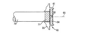
ノズルアセンブリ14は、本体であるブロック20と流体連通しており、図示の形態では、ノズルアセンブリ14は、ノズル体32及びノズル体32に取り付けられるノズル部材34を備える。ノズル体32は同じく316級ステンレス鋼から形成されることが好都合であり、前フランジ35、ブロック20内に部分的に受け入れられる後方に延びるステム36、及びステム36内に軸方向に延び前フランジ35で出口38となる貫通孔37を有する。ノズル部材34が貫通孔37の出口38に被さるようにノズル部材34を所定位置に取り付けるために、前フランジ35に適当なマウント40が設けられる。好都合には、マウント40は、ノズル部材34を所定位置に保持するためにノズル部材34の縁に圧着することができるカラー41(又はカラーの一部)を備える。ノズル部材34を前フランジ35に固定する他の方法としては、限定はされないが接着がある。取り付けは、アクチュエータアセンブリ16の影響下で宝石(ジュエル)をわずかに(1ミクロン程度)軸方向に移動させるようなものである。
The nozzle assembly 14 is in fluid communication with the
ステム36が前フランジ35から後方に延びているその最初の外側部分は、平らな円筒面44を備えており、その目的はより詳細に後述する。円筒面44の後縁はカラー46の形状となり、カラー46は、本体の前室22内への滑り嵌め部分である。図から分かるように、カラー46の周りには環状溝47が設けられ、そこにOリングシール48を嵌めて、室22内の流体がステム36の外面を伝って逃げるのを防止することができる。最後に、ステム36の後方の外周面49は、本体部20の中間部26と協働して本体内にノズル体を保持するようなサイズ及び形状にされる。図示のように、これは、本体の中間部26及びノズル体の後方外周面49に互いに螺合するねじを形成することによって得られる。本体内にノズル体32を保持する他の手段を用いることもできるが、ねじ山は、以下の説明から明らかなようにさらなる利点を有する。
The first outer portion of the
ステム36は、本体部20の前室22を通る場所に、貫通孔37を室22と連通させる1つ又は複数の半径方向のポート50を有することにも留意されたい。
It should also be noted that the
ノズル部材34は、所望の寸法の放出開口が貫通している宝石によって画定されることが好ましい。穿孔したサファイア石を用いることが当該技術分野において既知である。代替的なノズル部材としては、貫通孔の出口38に被さるようにフランジ35の前面に圧着(クリンプ)又は接着することができる箔がある。
The
液滴発生を行うためには、ノズル部材をインク源に対して所定の周波数で振動させる。本明細書に記載の液滴発生器の実施形態では、これは、本体部20及びノズル体32の平行面部分同士の間に振動作用を加えることによって行われる。図示の形態では、振動作用は、本体部20の前面54とノズル体32の前フランジ35の後面との間で発生させられる。しかしながら、構成部品20及び32は実質的に硬質の材料で形成されるため、振動はノズル体32を通してノズル部材34に伝達される。
In order to generate droplets, the nozzle member is vibrated at a predetermined frequency with respect to the ink source. In the embodiment of the droplet generator described herein, this is done by applying a vibrating action between the parallel surface portions of the
従来の方法では、振動源は、1つ又は複数、この場合は2つの圧電結晶アクチュエータ60である。これらは、絶縁スリーブ62に取り付けられ、絶縁スリーブ62はさらに、ノズル体32のステム36に形成される平らな円筒面44の周りに嵌められる。ノズル体と本体との間のねじ構成は、種々の構成部品の容易な組み立てを可能にし、圧電結晶60に対する軸方向の締め付け力が確実に維持される。
In conventional methods, the vibration source is one or more, in this case two
結晶60は、適当な駆動回路(図示せず)から駆動される。正の駆動端子64が結晶間に挟まれるように図示されている。各結晶の他方の側は、接地される本体部20を介して接地される。
The
好ましいか又は必要な振動形態としては、ノズル部材34がステム36及び室22の軸にほぼ沿って振動させられるものである。しかしながら、他の形態も起こる可能性があり、これら他の形態は、円筒面44がその軸に沿った変形以外の形で変形しないようにすることによって(事実上なくならないとしても)減らされる。絶縁スリーブ62が強力であるほど、他の振動形態が液滴発生性能を低下させることが少なくなる。
A preferred or necessary form of vibration is that the
使用時には、ポート29から供給されるインクは、貫通孔37を通ってノズル部材の後面に達する。続いて、結晶60の作動により、ノズル部材34が噴射軸65(図2)にほぼ沿って振動すると、インクがノズル開口を通って流れて液滴になる。
In use, the ink supplied from the
本発明による液滴発生器では、始動/停止機構18が組み込まれることが重要である。このような機構を含む理由は、本発明者らの欧州特許第0482123号に記載されているとおりである。しかしながら、(ノズル部材が変位するという)この速度変調用途においてこのような設備を実施することは、特に始動/停止機構の主構成要素の固有振動が発生器の動作周波数範囲内にあるという重大な問題があった。したがって、慎重に制御しなければ、始動/停止機構は変調に干渉することになる。 In the drop generator according to the invention, it is important that a start / stop mechanism 18 is incorporated. The reason for including such a mechanism is as described in our European Patent No. 0482123. However, implementing such equipment in this speed modulation application (where the nozzle member is displaced) is particularly critical that the natural vibrations of the main components of the start / stop mechanism are within the operating frequency range of the generator. There was a problem. Thus, if not carefully controlled, the start / stop mechanism will interfere with the modulation.
図示のように、主な始動/停止要素はプランジャ70の形態の閉鎖手段を備え、それは実質的に室22及び円筒面44と同軸、したがって噴射軸65上に設けられる。プランジャ70は、ノズル体のステム36及びノズル部材自体ともほぼ同軸上にある。実際には、図1に示されるように、プランジャは貫通孔37の中心を通る。プランジャ70は、その自由端にエラストマーシール71を含み、このシールはノズル部材34の後面と接触して、インクがノズル部材を不意に通過するのを防止する。
As shown, the main start / stop element comprises a closing means in the form of a
プランジャ70は、本体部20の後室24に被さるソレノイド74によって、ノズル部材と接触する閉位置に関して出入りするように変位する。プランジャをノズル部材34に対して付勢するために、ばね76が設けられる。
The
図示の形態では、ばね76は、プランジャ70の後端に設けられた軸方向孔78内に着座している。止めねじ80及び止めねじと接触して止めねじによって変位可能なバックストップ82を含む調整機構が設けられる。バックストップ82は、インクが室24から後方に逃げるのを防止するための環状シール83を有する。使用時には、止めねじ80をその取り付けボス84内で回転させて、バックストップ82を位置決めすることで、ソレノイド74の影響下でのプランジャ70の移動を制限する。すると、これによってプランジャとノズル部材34との間に動作クリアランスができる。通常、動作クリアランスは、流体(インク)の共鳴が装置の動作特性に影響を及ぼすことができないほど小さい約200ミクロンに設定される。
In the illustrated form, the
始動/停止機構がシステムの変調特性に及ぼす影響を最小限に抑えるために、始動/停止機構は、液滴発生器の動作中は変調プロセスから事実上分離又は分断される。これは、欧州特許第0482123号に記載の構成とは対照的であり、本明細書に示す形態では、本体部20に対してプランジャ70を実質的にロックすることによって行われる。このために、ソレノイド74に通電してプランジャ70を開位置に後退させると、プランジャはバックストップ82に対してしっかりと接触保持される。このように、プランジャは、事実上所定位置にロックされ、変調プロセスに実質的に影響を及ぼさない。
In order to minimize the effect of the start / stop mechanism on the modulation characteristics of the system, the start / stop mechanism is effectively decoupled or disconnected from the modulation process during operation of the droplet generator. This is in contrast to the configuration described in EP 0482123, and in the form shown here, this is done by substantially locking the
動作システムは、ソレノイド74が通電され、プランジャ70が開位置に後退してロックされた直後に、動作電圧が結晶60に加えられるように構成される。したがって、プランジャは、その軸に沿って往復不能となり、変調に影響を及ぼすことができない。
The operating system is configured such that an operating voltage is applied to the
使用時には、液滴発生器が連続式インクジェットプリンタのプリントヘッドアセンブリに堅固に締着されて、結晶60に加えられる振動駆動電流が振動を生成するが、この振動は、ノズル34の質量が本体部20の質量よりも大幅に小さく、発生器自体が移動できないため、ノズル部材の振動にほぼ完全に変換される。
In use, the drop generator is securely fastened to the printhead assembly of a continuous ink jet printer, and the vibration drive current applied to the
ポリエーテルエーテルケトン(PEEK)から形成された本体で実験が行われたが、構造的により剛直な性質のステンレス鋼を用いれば、所与のサイズの場合、ノズル部材の望ましくない振動形態がより良好に抑制される。 Experiments have been conducted with a body formed from polyetheretherketone (PEEK), but with a structurally more rigid nature of stainless steel, for a given size, the undesirable vibration form of the nozzle member is better To be suppressed.
本明細書に記載の液滴発生器は、約200kHzの共鳴周波数を有することが分かる。これは、64〜128kHzの範囲の通常の動作周波数とは対照的であるが、本明細書に記載の装置は、試験中、50〜150kHz範囲の周波数で動作して好結果を示している。したがって、この液滴発生器は、粘度及び温度の異なるインクで動作するように容易に調整できることが理解されるであろう。 It can be seen that the drop generator described herein has a resonant frequency of about 200 kHz. This is in contrast to normal operating frequencies in the range of 64 to 128 kHz, but the devices described herein have been successful in operating at frequencies in the range of 50 to 150 kHz during testing. Thus, it will be appreciated that the drop generator can be easily adjusted to work with inks of different viscosities and temperatures.
上述した液滴発生器のさらなる特性は、音響エネルギーのほぼ全てがノズル部材34の振動に加えられるため、インクには音響エネルギーがほぼ加えられず、その結果、インクの共鳴(複数可)を無視できることである。変調の差は、インクとノズルとの間の相互作用によってのみ決まる。
An additional characteristic of the drop generator described above is that almost all of the acoustic energy is applied to the vibration of the
図3は、11種類の異なるインクに関して変調を開始させるのに必要な変調電圧を示すプロットである。図から分かるように、変調は、試験したインクの全てに関して、さらなる調整を全く必要とせずにこのタイプの装置の標準的な動作電圧範囲(ウインドウ)内で良好に達成することができる。これは、異なるインクで機能するには駆動ロッドの交換が通常必要である本発明者らのAシリーズプリンタで現在用いられている圧力変調液滴発生器とは対照的である。 FIG. 3 is a plot showing the modulation voltage required to initiate modulation for 11 different inks. As can be seen, the modulation can be well achieved within the standard operating voltage range (window) of this type of device for all of the inks tested without requiring any further adjustment. This is in contrast to the pressure-modulated droplet generator currently used in our A-series printers, which typically require replacement of the drive rod to function with different inks.
10 液滴発生器
12 本体
14 ノズルアセンブリ
16 アクチュエータアセンブリ
18 停止・始動機構
20 ブロック(本体部)
22、24 室
32 ノズル体
34 ノズル部材
36 ステム
37 貫通孔
44 円筒面
60 結晶(アクチュエータ)
65 噴射軸
70 プランジャ
74 ソレノイド
DESCRIPTION OF
22, 24
65
Claims (11)
流体室(22、24、37)と、
該流体室(22、24、37)からの出口を画定するノズル(34)と、
使用時に、該ノズル(34)を通して噴射軸(65)に沿って放出される流体の流れが液滴になるように、前記流体室(22、24、37)に対して前記ノズル(34)を動作周波数で振動させるアクチュエータ(60)と、を備え、
前記流体室(22、24、37)は、実質的に硬質であり実質的に不動の本体(20、32)内に画定され、
前記アクチュエータ(60)の出力は、前記本体(20、32)に対して前記ノズル(34)を前記噴射軸(65)にほぼ沿って振動させるために加えられることを特徴とする、液滴発生器。 A droplet generator (10) having an operating frequency and a resonant frequency substantially higher than the operating frequency,
Fluid chambers (22, 24, 37);
A nozzle (34) defining an outlet from the fluid chamber (22, 24, 37);
In use, the nozzle (34) is moved relative to the fluid chamber (22, 24, 37) so that the fluid flow discharged along the ejection axis (65) through the nozzle (34) is droplets. An actuator (60) that vibrates at an operating frequency,
The fluid chamber (22, 24, 37) is defined within a substantially rigid and substantially stationary body (20, 32);
Droplet generation, characterized in that the output of the actuator (60) is applied to the body (20, 32) to vibrate the nozzle (34) substantially along the ejection axis (65) vessel.
流体室(22、24、37)と、
該流体室(22、24、37)からの出口を画定するノズル(34)と、
使用時に、該ノズル(34)を通して噴射軸(65)に沿って放出される流体の流れが液滴になるように、前記流体室(22、24、37)に対して前記ノズル(34)を振動させるように動作可能であるアクチュエータ(60)と、を備えた液滴発生器において、
前記流体室(22、24、37)を通り、且つ前記アクチュエータ(60)が動作中ではないときに流体が前記ノズル(34)を通るのを防止するように前記ノズル(34)と係合可能であり、前記アクチュエータ(60)が動作中であるときに移動を抑制される閉鎖手段(70)を備えたことを特徴とする液滴発生器。 A droplet generator (10) comprising:
Fluid chambers (22, 24, 37);
A nozzle (34) defining an outlet from the fluid chamber (22, 24, 37);
In use, the nozzle (34) is moved relative to the fluid chamber (22, 24, 37) so that the fluid flow discharged along the ejection axis (65) through the nozzle (34) is droplets. A droplet generator comprising an actuator (60) operable to vibrate;
Engageable with the nozzle (34) through the fluid chamber (22, 24, 37) and to prevent fluid from passing through the nozzle (34) when the actuator (60) is not in operation A drop generator comprising: closing means (70) that is restrained from moving when the actuator (60) is in operation.
Applications Claiming Priority (2)
| Application Number | Priority Date | Filing Date | Title |
|---|---|---|---|
| EP04255578A EP1637329A1 (en) | 2004-09-15 | 2004-09-15 | Droplet generator |
| PCT/EP2005/054577 WO2006030018A1 (en) | 2004-09-15 | 2005-09-14 | Droplet generator |
Publications (1)
| Publication Number | Publication Date |
|---|---|
| JP2008512277A true JP2008512277A (en) | 2008-04-24 |
Family
ID=34930654
Family Applications (1)
| Application Number | Title | Priority Date | Filing Date |
|---|---|---|---|
| JP2007530722A Pending JP2008512277A (en) | 2004-09-15 | 2005-09-14 | Droplet generator |
Country Status (7)
| Country | Link |
|---|---|
| US (2) | US8662646B2 (en) |
| EP (3) | EP1637329A1 (en) |
| JP (1) | JP2008512277A (en) |
| CN (1) | CN100537239C (en) |
| AT (1) | ATE467510T1 (en) |
| DE (1) | DE602005021262D1 (en) |
| WO (1) | WO2006030018A1 (en) |
Families Citing this family (6)
| Publication number | Priority date | Publication date | Assignee | Title |
|---|---|---|---|---|
| EP2058130A1 (en) | 2007-11-09 | 2009-05-13 | Nederlandse Organisatie voor toegepast- natuurwetenschappelijk onderzoek TNO | Droplet selection mechanism |
| EP2058129A1 (en) * | 2007-11-09 | 2009-05-13 | Nederlandse Organisatie voor toegepast- natuurwetenschappelijk onderzoek TNO | Droplet break-up device |
| EP2058131A1 (en) | 2007-11-09 | 2009-05-13 | Nederlandse Organisatie voor toegepast- natuurwetenschappelijk onderzoek TNO | Droplet selection mechanism |
| US10449404B2 (en) * | 2014-11-26 | 2019-10-22 | Barxbell, Inc. | Exercise apparatus |
| CN109454994B (en) * | 2018-11-12 | 2023-10-20 | 上海美创力罗特维尔电子机械科技有限公司 | Clamping type crystal oscillator assembly of monolithic piezoelectric crystal |
| CN112495675B (en) * | 2020-10-27 | 2022-04-01 | 浙江大学 | High flux micro-droplet generating device based on multi-source excitation |
Family Cites Families (24)
| Publication number | Priority date | Publication date | Assignee | Title |
|---|---|---|---|---|
| US3972474A (en) * | 1974-11-01 | 1976-08-03 | A. B. Dick Company | Miniature ink jet nozzle |
| JPS5168113A (en) | 1974-12-10 | 1976-06-12 | Matsushita Electric Ind Co Ltd | RAJIOJUSHINKI |
| US4068144A (en) * | 1976-09-20 | 1978-01-10 | Recognition Equipment Incorporated | Liquid jet modulator with piezoelectric hemispheral transducer |
| US4095232A (en) * | 1977-07-18 | 1978-06-13 | The Mead Corporation | Apparatus for producing multiple uniform fluid filaments and drops |
| NL7710162A (en) | 1977-09-16 | 1979-03-20 | Philips Nv | METHOD FOR MANUFACTURING AN OPTICALLY READABLE INFORMATION DISK USING A FLAT, STIFFENING HEAT CONDUCTIVE PLATE OF INORGANIC MATERIAL |
| JPS593149B2 (en) | 1977-10-07 | 1984-01-23 | 株式会社日立製作所 | Inkjet recording device |
| JPS5530939A (en) | 1978-08-26 | 1980-03-05 | Ricoh Co Ltd | Ink jet recording head |
| JPS56104065A (en) * | 1980-01-23 | 1981-08-19 | Hitachi Ltd | Preparing device for ink particle |
| JPS5738159A (en) * | 1980-08-20 | 1982-03-02 | Ricoh Co Ltd | Exciting system of printing head in ink jet printing device |
| JPS5896565A (en) * | 1981-12-04 | 1983-06-08 | Hitachi Ltd | Ink jet recording method |
| JPS61169571A (en) | 1985-01-21 | 1986-07-31 | 田賀 喜一 | Wire drive apparatus of ceiling receiving housing |
| JPS61175046A (en) | 1985-01-31 | 1986-08-06 | Ricoh Co Ltd | Structure of head portion of ink jet printer |
| JPS61175451A (en) | 1985-01-31 | 1986-08-07 | 松下精工株式会社 | Air conditioner |
| US4727379A (en) | 1986-07-09 | 1988-02-23 | Vidoejet Systems International, Inc. | Accoustically soft ink jet nozzle assembly |
| JPS6327265A (en) * | 1986-07-18 | 1988-02-04 | Ricoh Co Ltd | Ink jet recorder apparatus |
| GB8915819D0 (en) | 1989-07-11 | 1989-08-31 | Domino Printing Sciences Plc | Continuous ink jet printer |
| US5980034A (en) * | 1996-03-11 | 1999-11-09 | Videojet Systems International, Inc. | Cross flow nozzle system for an ink jet printer |
| US6537505B1 (en) * | 1998-02-20 | 2003-03-25 | Bio Dot, Inc. | Reagent dispensing valve |
| JP2002107143A (en) | 2000-10-02 | 2002-04-10 | Hitachi Constr Mach Co Ltd | Ground angle detector and angle-detecting apparatus |
| JP2002137422A (en) * | 2000-10-31 | 2002-05-14 | Fuji Photo Film Co Ltd | Image recording method and printer employing the method |
| DE10135735B4 (en) * | 2001-07-21 | 2009-04-16 | Robert Bosch Gmbh | Method for operating an internal combustion engine, in particular with direct injection, and computer program and control and / or regulating device |
| US6655796B2 (en) | 2001-12-20 | 2003-12-02 | Eastman Kodak Company | Post-print treatment for ink jet printing apparatus |
| US20050253905A1 (en) * | 2002-07-26 | 2005-11-17 | Melissa Orme-Marmerelis | Droplet generation by transverse disturbances |
| JP4123897B2 (en) | 2002-10-28 | 2008-07-23 | 株式会社エルエーシー | Inkjet nozzle |
-
2004
- 2004-09-15 EP EP04255578A patent/EP1637329A1/en not_active Withdrawn
-
2005
- 2005-09-14 DE DE602005021262T patent/DE602005021262D1/en active Active
- 2005-09-14 EP EP09007289A patent/EP2100737B1/en active Active
- 2005-09-14 WO PCT/EP2005/054577 patent/WO2006030018A1/en active Application Filing
- 2005-09-14 JP JP2007530722A patent/JP2008512277A/en active Pending
- 2005-09-14 US US11/660,651 patent/US8662646B2/en active Active
- 2005-09-14 CN CN200580031119.4A patent/CN100537239C/en active Active
- 2005-09-14 EP EP05789444A patent/EP1789261B1/en not_active Expired - Fee Related
- 2005-09-14 AT AT09007289T patent/ATE467510T1/en not_active IP Right Cessation
-
2013
- 2013-04-19 US US13/866,082 patent/US9174434B2/en active Active
Also Published As
| Publication number | Publication date |
|---|---|
| EP1789261A1 (en) | 2007-05-30 |
| US8662646B2 (en) | 2014-03-04 |
| ATE467510T1 (en) | 2010-05-15 |
| EP1789261B1 (en) | 2011-07-20 |
| WO2006030018A9 (en) | 2011-03-10 |
| WO2006030018A1 (en) | 2006-03-23 |
| US9174434B2 (en) | 2015-11-03 |
| US20140347425A1 (en) | 2014-11-27 |
| EP1637329A1 (en) | 2006-03-22 |
| EP2100737B1 (en) | 2010-05-12 |
| EP2100737A1 (en) | 2009-09-16 |
| US20070257970A1 (en) | 2007-11-08 |
| CN100537239C (en) | 2009-09-09 |
| DE602005021262D1 (en) | 2010-06-24 |
| CN101048283A (en) | 2007-10-03 |
Similar Documents
| Publication | Publication Date | Title |
|---|---|---|
| US9174434B2 (en) | Droplet generator | |
| US6474786B2 (en) | Micromachined two-dimensional array droplet ejectors | |
| EP0787589B1 (en) | Ink jet recording head | |
| US4032928A (en) | Wideband ink jet modulator | |
| US7777395B2 (en) | Continuous drop emitter with reduced stimulation crosstalk | |
| KR101603807B1 (en) | Method and apparatus to provide variable drop size ejection by dampening pressure inside a pumping chamber | |
| WO1991000808A1 (en) | Continuous ink jet printer | |
| US20090021567A1 (en) | Printing system particle removal device and method | |
| EP0054114B1 (en) | Liquid droplet forming apparatus | |
| EP1328405B1 (en) | A droplet generator for a continuous stream ink jet print head | |
| JP3580343B2 (en) | Ink jet recording device | |
| JP2001205802A (en) | Ink-jet recording apparatus | |
| JPS593149B2 (en) | Inkjet recording device | |
| US20100182363A1 (en) | Liquid discharging apparatus and control method thereof | |
| JP2001150674A (en) | Ink-jet recording apparatus and its nozzle | |
| JPH05212862A (en) | Continuous ink jet printer | |
| JPH0234343A (en) | On-demand type ink-jet head | |
| JP2001191516A (en) | Ink jet recorder | |
| JPH04187440A (en) | Ink jet recorder | |
| JP2002254655A (en) | Ink jet recording device and manufacturing method therefor | |
| JP2006088392A (en) | Inkjet recording head and inkjet recording device | |
| JP2003311401A (en) | Device for spouting molten metal | |
| JP2001138509A (en) | Ink jet recorder | |
| JP2002283561A (en) | Actuator and ink jet head | |
| JPH0243054A (en) | Ink jet recording apparatus |
Legal Events
| Date | Code | Title | Description |
|---|---|---|---|
| A977 | Report on retrieval |
Free format text: JAPANESE INTERMEDIATE CODE: A971007 Effective date: 20090218 |
|
| A131 | Notification of reasons for refusal |
Free format text: JAPANESE INTERMEDIATE CODE: A131 Effective date: 20090224 |
|
| A601 | Written request for extension of time |
Free format text: JAPANESE INTERMEDIATE CODE: A601 Effective date: 20090518 |
|
| A602 | Written permission of extension of time |
Free format text: JAPANESE INTERMEDIATE CODE: A602 Effective date: 20090525 |
|
| A02 | Decision of refusal |
Free format text: JAPANESE INTERMEDIATE CODE: A02 Effective date: 20090818 |