JP2008507694A - Read head for optical diagnostic equipment - Google Patents
Read head for optical diagnostic equipment Download PDFInfo
- Publication number
- JP2008507694A JP2008507694A JP2007522520A JP2007522520A JP2008507694A JP 2008507694 A JP2008507694 A JP 2008507694A JP 2007522520 A JP2007522520 A JP 2007522520A JP 2007522520 A JP2007522520 A JP 2007522520A JP 2008507694 A JP2008507694 A JP 2008507694A
- Authority
- JP
- Japan
- Prior art keywords
- sample
- rectangular
- sample table
- image
- view
- Prior art date
- Legal status (The legal status is an assumption and is not a legal conclusion. Google has not performed a legal analysis and makes no representation as to the accuracy of the status listed.)
- Pending
Links
Images


Classifications
-
- G—PHYSICS
- G01—MEASURING; TESTING
- G01N—INVESTIGATING OR ANALYSING MATERIALS BY DETERMINING THEIR CHEMICAL OR PHYSICAL PROPERTIES
- G01N21/00—Investigating or analysing materials by the use of optical means, i.e. using sub-millimetre waves, infrared, visible or ultraviolet light
- G01N21/84—Systems specially adapted for particular applications
- G01N21/8483—Investigating reagent band
-
- Y—GENERAL TAGGING OF NEW TECHNOLOGICAL DEVELOPMENTS; GENERAL TAGGING OF CROSS-SECTIONAL TECHNOLOGIES SPANNING OVER SEVERAL SECTIONS OF THE IPC; TECHNICAL SUBJECTS COVERED BY FORMER USPC CROSS-REFERENCE ART COLLECTIONS [XRACs] AND DIGESTS
- Y10—TECHNICAL SUBJECTS COVERED BY FORMER USPC
- Y10T—TECHNICAL SUBJECTS COVERED BY FORMER US CLASSIFICATION
- Y10T436/00—Chemistry: analytical and immunological testing
- Y10T436/11—Automated chemical analysis
- Y10T436/110833—Utilizing a moving indicator strip or tape
-
- Y—GENERAL TAGGING OF NEW TECHNOLOGICAL DEVELOPMENTS; GENERAL TAGGING OF CROSS-SECTIONAL TECHNOLOGIES SPANNING OVER SEVERAL SECTIONS OF THE IPC; TECHNICAL SUBJECTS COVERED BY FORMER USPC CROSS-REFERENCE ART COLLECTIONS [XRACs] AND DIGESTS
- Y10—TECHNICAL SUBJECTS COVERED BY FORMER USPC
- Y10T—TECHNICAL SUBJECTS COVERED BY FORMER US CLASSIFICATION
- Y10T436/00—Chemistry: analytical and immunological testing
- Y10T436/11—Automated chemical analysis
- Y10T436/112499—Automated chemical analysis with sample on test slide
-
- Y—GENERAL TAGGING OF NEW TECHNOLOGICAL DEVELOPMENTS; GENERAL TAGGING OF CROSS-SECTIONAL TECHNOLOGIES SPANNING OVER SEVERAL SECTIONS OF THE IPC; TECHNICAL SUBJECTS COVERED BY FORMER USPC CROSS-REFERENCE ART COLLECTIONS [XRACs] AND DIGESTS
- Y10—TECHNICAL SUBJECTS COVERED BY FORMER USPC
- Y10T—TECHNICAL SUBJECTS COVERED BY FORMER US CLASSIFICATION
- Y10T436/00—Chemistry: analytical and immunological testing
- Y10T436/14—Heterocyclic carbon compound [i.e., O, S, N, Se, Te, as only ring hetero atom]
- Y10T436/142222—Hetero-O [e.g., ascorbic acid, etc.]
- Y10T436/143333—Saccharide [e.g., DNA, etc.]
- Y10T436/144444—Glucose
Abstract
測光診断装置のための読み取りヘッドは、測光診断装置内への組み込み用に適応されたハウジング、およびハウジングと効果的に結合する長方形の試料テーブルとを含む。試料テーブルは、試料と反応し、試料の成分の量あるいは特性に従って色彩を変化させるように構成される複数の試験領域を有するタイプの長方形の試薬試料媒体を支持するように構成される。光源は、試料テーブルを照射するために提供される。長方形の視界を有する画像装置はハウジングに連結され、長方形の視界は試料テーブルの少なくとも一部分を含む。走査機構は、試料テーブルに対して視界を移動させるように構成される。 A read head for a photometric diagnostic device includes a housing adapted for incorporation into the photometric diagnostic device, and a rectangular sample table that effectively couples to the housing. The sample table is configured to support a rectangular reagent sample medium of a type having a plurality of test areas that are configured to react with the sample and change color according to the amount or characteristics of the sample components. A light source is provided to illuminate the sample table. An imaging device having a rectangular field of view is coupled to the housing, the rectangular field of view including at least a portion of the sample table. The scanning mechanism is configured to move the field of view relative to the sample table.
Description
本発明は、一般に臨床化学の分野に関するものである。特に、本発明は、尿または血液のような液体試料に以下のように接触するサンプル媒体上の一つ以上の試験領域に関係する色彩変化を分析する画像診断システムのための読み取りヘッドに関するものである。 The present invention relates generally to the field of clinical chemistry. In particular, the present invention relates to a read head for a diagnostic imaging system that analyzes color changes related to one or more test areas on a sample medium that contacts a liquid sample such as urine or blood as follows. is there.
この出願の全体にわたって、特定した引例で様々な特許を参照する。この出願で参照された特許の開示は、参照によってこの開示へ組込まれる。 Throughout this application, various patents are referenced in specific references. The disclosures of the patents referenced in this application are incorporated into this disclosure by reference.
試薬試験片のようなサンプル媒体は、臨床化学の分野において広く使用される。試験片は、通常、その長さに沿って離間された一つ以上の試験領域を有し、各試験領域は、液体試料との接触に応じて色彩変化を受けることができる。液体試料は、通常、興味のある一つ以上の成分または特性を含む。これらの成分または特性の存在および濃度は、試験片によって受けた色彩変化の分析によって決定できる。通常、この分析は、試験領域または試験パッドと色度標準またはスケール間の色彩比較を含む。このように、試薬試験片は、疾病および他の健康問題の存在を分析する際に医者を支援する。 Sample media such as reagent test strips are widely used in the field of clinical chemistry. A test strip typically has one or more test areas spaced along its length, and each test area can undergo a color change in response to contact with a liquid sample. A liquid sample typically includes one or more components or characteristics of interest. The presence and concentration of these components or characteristics can be determined by analysis of the color change received by the test strip. This analysis typically involves a color comparison between the test area or test pad and the chromaticity standard or scale. Thus, the reagent test strip assists the physician in analyzing the presence of illness and other health problems.
肉眼で行われた色彩比較は、曖昧な測定に結びつく。今日、試験片の色彩変化を読み取るために反射率測光を使用する小片読み取り装置が存在する。これらの装置は、特別の波長範囲または帯域幅内の試験片の色彩変化を正確に決定する。いくつかの装置は、さらにこの帯域幅外の色彩不統一を測定する。例えば、バイエルヘルスケアLLC(メッドフィールド、マサチューセッツ)のバイエルヘルスケアの診断部門によってCLINITEK(登録商標)商標の下で販売され、および/または米国特許番号5,408,535および5,877,863(‘863特許)において開示され、それらの両方が明細書の参照によって完全に組込まれるような装置は、MULTISTIX(登録商標)(バイエル)試薬片の尿試料内における血液のトレースのような特徴を検出することができる。尿試料が、MULTISTIX(登録商標)試薬片の試験パッドに接触した後、そのままの血球が、黄色の試験領域上で小さな緑のしみとして現われる。これらの既存の小片読み取り装置は、試験パッドの全体色および緑の小さなしみの両方を検出することができる。 Color comparison made with the naked eye leads to ambiguous measurements. Today, there are small piece readers that use reflectance photometry to read the color change of a test piece. These devices accurately determine the color change of the specimen within a particular wavelength range or bandwidth. Some devices also measure color inconsistencies outside this bandwidth. For example, sold under the CLINITEK® trademark by the Bayer Healthcare Diagnostics Department of Bayer Healthcare LLC (Medfield, Massachusetts) and / or US Patent Nos. 5,408,535 and 5,877,863 ( The device disclosed in the '863 patent), both of which are fully incorporated by reference, detects features such as blood traces in the urine sample of the MULTISTIX® (Bayer) reagent strip. can do. After the urine sample contacts the MULTISTIX® reagent strip test pad, intact blood cells appear as small green spots on the yellow test area. These existing strip readers can detect both the overall color of the test pad and small green spots.
‘863特許において開示されたように、これらの装置は、典型的に、試験片を照射するように構成され、CCD装置などのような一つ以上の画像装置または検知器によってとらえられ照射された試験片の画像化を可能にする読み取り装置を含む。比較的高いアスペクト比(長さと幅との比率)を有するこれらの画像装置は、延長される傾向がある。高いアスペクト比は、有利なことに、長方形の試験片の名目上全長に沿った画像をとらえるために、これらの画像装置に十分に延長された視界を提供する。 As disclosed in the '863 patent, these devices are typically configured to illuminate a specimen and are captured and illuminated by one or more imaging devices or detectors such as a CCD device or the like. Includes a reader that allows imaging of the specimen. These imaging devices with relatively high aspect ratios (length to width ratio) tend to be extended. The high aspect ratio advantageously provides a sufficiently extended field of view for these imaging devices to capture images along the nominal length of the rectangular specimen.
しかしながら、これらの高いアスペクト比の画像装置に関係するトレードオフは、視界が比較的狭く、したがって同様に狭い画像をとらえる傾向がある。とらえられた画像は、典型的に、試験片の全試験領域の小さなスライスまたは小片だけを表わす。この‘スライス’は、有用な試験結果を生成するために一般に十分であるが、解像度を改善するために装置のダイナミックレンジを増加させるように、画像幅を増加することは多くの用途において望ましいかもしれない。広い画像をとらえるために大きなCCDデバイスを使用してもよいが、試験片の名目上の全長および幅の画像をとらえるために十分大きなCCDは、法外に高価になる場合もある。 However, the tradeoffs associated with these high aspect ratio imaging devices have a relatively narrow field of view and therefore tend to capture narrow images as well. The captured image typically represents only a small slice or piece of the entire test area of the test piece. This 'slice' is generally sufficient to produce useful test results, but increasing the image width may be desirable in many applications to increase the dynamic range of the device to improve resolution. unknown. Large CCD devices may be used to capture wide images, but CCDs that are large enough to capture images of the nominal length and width of the specimen may be prohibitively expensive.
したがって、改善された診断試験装置用に、高いアスペクト比の画像装置でとらえられた画像の幅を効率的に拡げる必要性が存在する。 Therefore, there is a need for an improved diagnostic test apparatus that efficiently expands the width of images captured with high aspect ratio imaging devices.
要約
この発明の1つの態様では、目標領域を照射し、目標領域から光を受ける測光診断装置のための読み取りヘッドを含む。読み取りヘッドは、測光診断装置内への組み込み用に適応されたハウジング、および第一の波長の光を放射するように構成された第一の光源を含む。第二の光源もハウジングに連結され、第二の波長の光を放射するように構成される。縦と横の寸法が少なくとも2:1のアスペクト比を有している長方形の試料テーブルも提供される。試料テーブルは、その上に一定間隔で配置された複数の試験領域を有する長方形の試薬試料媒体を支持するように構成され、試験領域の各々は試料と反応するように構成され、試料の成分の量または特性に従って色彩を変化させるように構成される。光ガイドが、光源の各々から光を受けるために配置され、光源のうちの1つだけが照射される場合に、1つの光源からの実質上すべての光を試料テーブルの方へ伝達する。長方形の画像捕獲装置は目標領域から光を受け、縦と横の寸法が少なくとも2:1のアスペクト比を有している。走査機構は、画像捕獲装置に対して試料テーブルの画像を移動させるように構成される。
Summary One aspect of the invention includes a read head for a photometric diagnostic device that illuminates a target area and receives light from the target area. The read head includes a housing adapted for incorporation into the photometric diagnostic device and a first light source configured to emit light of a first wavelength. A second light source is also coupled to the housing and is configured to emit light of a second wavelength. A rectangular sample table is also provided having an aspect ratio of at least 2: 1 longitudinal and lateral dimensions. The sample table is configured to support a rectangular reagent sample medium having a plurality of test areas disposed thereon at regular intervals, each of the test areas being configured to react with the sample, Configured to change color according to quantity or characteristic. Light guides are arranged to receive light from each of the light sources and transmit substantially all of the light from one light source towards the sample table when only one of the light sources is illuminated. A rectangular image capture device receives light from a target area and has an aspect ratio of at least 2: 1 vertical and horizontal dimensions. The scanning mechanism is configured to move the image of the sample table relative to the image capture device.
本発明の別の態様において、測光診断装置のための読み取りヘッドは、測光診断装置内の組み込み用に適応されたハウジング、およびハウジングに効果的に接合された長方形の試料テーブルを含む。試料テーブルは、その上に一定間隔で配置された複数の試験領域を有するタイプの長方形の試薬試料媒体を支持するように構成され、試験領域の各々は試料と反応するように構成され、試料の成分の量あるいは特性に従って色彩を変化させる。光源は、試料テーブルを照射するために提供される。長方形の視界を有する画像装置は、ハウジングに連結され、長方形の視界は、試料テーブルの少なくとも一部を含む。走査機構は、試料テーブルに対して視界を移動させるように構成される。 In another aspect of the invention, a read head for a photometric diagnostic device includes a housing adapted for incorporation within the photometric diagnostic device and a rectangular sample table effectively joined to the housing. The sample table is configured to support a rectangular reagent sample medium of a type having a plurality of test areas disposed at regular intervals thereon, each of the test areas being configured to react with the sample, Change the color according to the amount or characteristics of the component. A light source is provided to illuminate the sample table. An imaging device having a rectangular field of view is coupled to the housing, the rectangular field of view including at least a portion of the sample table. The scanning mechanism is configured to move the field of view relative to the sample table.
本発明の別の態様は、測光診断装置を含んでいる。この装置は、ハウジングと、ハウジングと効果的に接合された長方形の試料テーブルとを含む。試料テーブルは、その上に既定した方向で長方形の試薬試料媒体を支持するように構成され、試料媒体は、その上に一定間隔で配置された複数の試験領域を有する。試験領域の各々は、試料と反応するように構成され、試料の成分の量あるいは特性に従って色彩を変化させる。光源は、試料テーブルを照射するように構成される。長方形の視界を有する長方形の画像装置は、ハウジングに連結され、長方形の視界は、試料テーブルの少なくとも一部を含む。走査機構は、試料テーブルに対して視界を移動させるように構成される。画像装置は、視界内に配置された試料媒体の部分の画像をとらえるように構成される。メモリーデバイスは、画像装置に連結され、プロセッサーは、メモリーデバイスおよび画像装置に連結される。プロセッサーは、走査機構を操作するように構成され、画像装置は、試料テーブルに対する視界の移動中に試料媒体の部分の画像をとらえるように構成される。メモリーデバイスは、合成画像を形成するためにとらえられた画像を格納するように構成され、プロセッサーは、合成画像を分析するように構成される。また、プロセッサーは、分析から分析値を導出し、それに対応する出力を生成するように構成される。 Another aspect of the present invention includes a photometric diagnostic device. The apparatus includes a housing and a rectangular sample table that is effectively joined to the housing. The sample table is configured to support a rectangular reagent sample medium in a predetermined direction thereon, the sample medium having a plurality of test areas disposed thereon at regular intervals. Each of the test areas is configured to react with the sample and change color according to the amount or characteristics of the sample components. The light source is configured to illuminate the sample table. A rectangular imaging device having a rectangular field of view is coupled to the housing, and the rectangular field of view includes at least a portion of the sample table. The scanning mechanism is configured to move the field of view relative to the sample table. The imaging device is configured to capture an image of a portion of the sample medium placed in the field of view. The memory device is coupled to the image device, and the processor is coupled to the memory device and the image device. The processor is configured to operate the scanning mechanism, and the imaging device is configured to capture an image of a portion of the sample medium during a field of view movement relative to the sample table. The memory device is configured to store an image captured to form a composite image, and the processor is configured to analyze the composite image. The processor is also configured to derive an analysis value from the analysis and generate a corresponding output.
本発明のさらなる態様は、その上に一定間隔で配置された複数の試験領域を有するタイプの試薬試料媒体を読むための方法を含み、試験領域の各々は、試料と反応し、試料の成分の量あるいは特性に従って色彩を変化させるように構成される。本方法は、測光診断装置の読み取りヘッドに関連する試料テーブルへ試料媒体を受けることを含み、試料テーブルは既定した方向に試料媒体を維持するように構成される。さらに、本方法は、試料テーブルに対して画像装置の視界を移動させ、移動中に画像装置で試験領域の画像をとらえ、合成画像を形成するために画像を合成することを含む。試料の成分の量あるいは特性は、その後の分析から導かれる。そして、その量に対応する出力信号が生成される。 A further aspect of the invention includes a method for reading a reagent sample medium of a type having a plurality of test regions spaced apart thereon, each of the test regions reacting with the sample and of the components of the sample Configured to change color according to quantity or characteristic. The method includes receiving a sample medium into a sample table associated with a read head of a photometric diagnostic apparatus, the sample table being configured to maintain the sample medium in a predetermined direction. The method further includes moving the field of view of the imaging device relative to the sample table, capturing an image of the test area with the imaging device during movement, and combining the images to form a composite image. The amount or characteristics of the sample components are derived from subsequent analysis. Then, an output signal corresponding to the amount is generated.
本発明のさらなる態様は、測光診断装置のための読み取りヘッドを含む。読み取りヘッドは、測光診断装置内に組み込むためのハウジング手段、およびその上に一定間隔で配置された複数の試験領域を有する長方形の試薬試料媒体を支持する長方形の試料テーブル手段を含む。試験領域の各々は、試料と反応し、試料の成分の量あるいは特性に従って色彩を変化させるように構成される。装置は、さらに、試料テーブル手段を照射する手段、およびハウジング手段に接続した画像化手段を含む。画像化手段は、試料テーブル手段の少なくとも一部を含む長方形の視界を有する。さらに、試料テーブルに対して視界を移動させるための走査手段も含む。 A further aspect of the invention includes a read head for a photometric diagnostic device. The read head includes housing means for incorporation into the photometric diagnostic apparatus and rectangular sample table means for supporting a rectangular reagent sample medium having a plurality of test areas disposed thereon at regular intervals. Each of the test areas is configured to react with the sample and change color according to the amount or characteristics of the sample components. The apparatus further includes means for illuminating the sample table means and imaging means connected to the housing means. The imaging means has a rectangular field of view including at least a portion of the sample table means. Further, scanning means for moving the field of view with respect to the sample table is included.
本発明のさらなる態様は、診断装置を収容する手段、および既定した方向で長方形の試薬試料媒体を支持するための長方形の試料テーブル手段を含む測光診断装置を含む。試料媒体は、その上に一定間隔で配置された複数の試験領域を有し、試験領域の各々は、試料と反応し、試料の成分の量あるいは特性に従って色彩を変化させるように構成される。装置は、さらに、試料テーブル手段を照射する照射手段、および長方形の視界内に配置された試料媒体の部分の画像をとらえるための画像化手段を含む。長方形の視界は、試料テーブル手段の少なくとも一部を含む。走査手段は、試料テーブル手段に対して視界を移動させるように含まれる。メモリー手段は、合成画像を形成するためにとられた画像を格納するために提供される。画像化手段、メモリー手段、および走査手段を操作するために、処理手段がメモリーデバイス、画像化手段、および走査手段に連結される。画像化手段は、試料テーブルに対して視界の移動中に試料媒体の一部の画像をとらえるように適応される。処理手段は、合成画像を分析し、分析から分析値を導出し、そしてそれに対応する出力を生成するために適応される。 A further aspect of the invention includes a photometric diagnostic device comprising means for receiving the diagnostic device and rectangular sample table means for supporting a rectangular reagent sample medium in a predetermined orientation. The sample medium has a plurality of test areas disposed thereon at regular intervals, each of the test areas being configured to react with the sample and change color according to the amount or characteristic of the sample components. The apparatus further includes an illuminating means for illuminating the sample table means and an imaging means for capturing an image of the portion of the sample medium disposed within the rectangular field of view. The rectangular field of view includes at least a portion of the sample table means. A scanning means is included to move the field of view relative to the sample table means. Memory means is provided for storing images taken to form a composite image. A processing means is coupled to the memory device, the imaging means, and the scanning means for operating the imaging means, the memory means, and the scanning means. The imaging means is adapted to capture an image of a portion of the sample medium while the field of view is moving relative to the sample table. The processing means is adapted to analyze the composite image, derive an analysis value from the analysis, and generate a corresponding output.
図面の簡潔な記述
上記および他の特徴並びにこの発明の利点は、添付した図面と関連して得られるこの発明の様々な様相の詳細な記述からより容易に明白になる。
BRIEF DESCRIPTION OF THE DRAWINGS The above and other features and advantages of the present invention will become more readily apparent from the detailed description of various aspects of the present invention obtained in conjunction with the accompanying drawings.
詳細な記述
以下の詳細な記述において、本発明の一部を形成する添付した図面が参照され、本発明が実行される特定の実施例が、例として示される。これらの実施例は、当業者が本発明を実施できるように十分詳細に記述され、その他の実施例を利用してもよいことは理解されるべきである。さらに、構造的および手続的なシステム的な変更が、本発明の精神および範囲から逸脱することなく行われることを理解すべきである。したがって、以下の詳細な記述は制限する意味ではなく、本発明の範囲は、引用される請求項およびそれらの均等物によって画定される。説明の明瞭化のために、添付した図面で示された同種の特徴は、同種の参照数字で表示され、図面における代替実施例で示されるような同様の特徴は、同様の参照数字で表示される。
DETAILED DESCRIPTION In the following detailed description, reference is made to the accompanying drawings that form a part hereof, and in which is shown by way of illustration specific embodiments in which the invention may be practiced. These embodiments are described in sufficient detail to enable those skilled in the art to practice the invention, and it should be understood that other embodiments may be utilized. Further, it should be understood that structural and procedural system changes may be made without departing from the spirit and scope of the invention. The following detailed description is, therefore, not to be taken in a limiting sense, and the scope of the present invention is defined by the appended claims and their equivalents. For clarity of explanation, like features shown in the accompanying drawings will be indicated with like reference numerals, and similar features as shown in alternative embodiments in the drawings will be indicated with like reference numerals. The
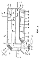
本発明の実施例の概要は、図1〜3を参照して提供される。本実施例は、試薬試料媒体を分析するために使用されるタイプの測光診断装置、例えば、上記で参照されたCLINITEK(登録商標)装置のための読み取りヘッド10を含む。読み取りヘッド10は、長方形の画像捕獲装置(あるいは検知器)70を横切って長方形の試料媒体40の画像を便利に走査するために構成された走査機構を備える。したがって、検知器70は、試料媒体40の部分の一連の画像をとらえ、それは、試料媒体40の合成画像を形成するために、例えば、メモリー74へ画像を保存することによって組み合わせられる。
An overview of embodiments of the present invention is provided with reference to FIGS. This example includes a read
1つの実施例において、走査機構は、目標領域と画像捕獲装置との間で回転可能に光学的に配置された鏡60を含む。アクチュエーター62は、画像捕獲装置70に関連する画像を走査する鏡60を選択的に回転するように構成される。
In one embodiment, the scanning mechanism includes a
別の実施例において、走査機構は、試料媒体40に対する傾斜角を持った視界72’’’(図5A)を有する画像捕獲装置70’を含む。アクチュエーター62’は、図2に示されるように、例えば試料媒体40の縦軸aに実質上平行な方向に、視界72’’’へおよび視界72’’’から試料テーブル42(およびその上に配置された試料媒体)を滑らせるように交互に構成される。
In another embodiment, the scanning mechanism includes an
当業者によく知られているように、試料媒体40は、その上に一定間隔で配置され、標本試料と反応して、患者の病状に従って、つまり試料の成分の量または特性に従って色彩を変化させる化学試薬に浸けられた紙パッドを有する典型的な尿検査片を含む。そのような媒体40の例は、前述のMULTISTIX(登録商標)試験片を含む。あるいは、試料媒体40は、従来のイムノ−分析カセット、例えば(図1において40’として仮想線で概略的に示されるように)試料と反応して患者の病状に従って有色線または線のパターンを明らかにする化学試薬に浸けられた領域を有するCLINITEST(登録商標)hCGカセット(バイエル)を含む。
As is well known to those skilled in the art, the
他の適切な試料媒体は、血液または尿のような流体が通る、例えばミクロンオーダーの幅の一連の狭いチャンネルを有する基板を典型的に含む従来のマイクロ流体デバイス(図1において40”として概略的に示される)を含む。チャンネルは、装置上の様々な試験領域へ流体を導く。これらの装置は、様々な試験が少量の流体だけを使用して、例えば液体の小滴を使用して実行されることを可能にする。典型的なマイクロ流体デバイスは、2002年2月26日に出願され、遠心力および/または毛細管力による流体の正確な移動および操作のための方法と装置と題された米国特許出願10/082,415に記述される。 Another suitable sample medium is schematically illustrated as a conventional microfluidic device (40 "in FIG. 1) typically comprising a substrate having a series of narrow channels, eg, on the order of microns, through which fluids such as blood or urine pass. Channels direct fluid to various test areas on the device, which perform various tests using only a small amount of fluid, for example using liquid droplets A typical microfluidic device was filed on Feb. 26, 2002 and entitled Method and Apparatus for Accurate Movement and Manipulation of Fluid by Centrifugal and / or Capillary Forces. U.S. patent application Ser. No. 10 / 082,415.
便宜と明瞭化のために、本発明の様々な実施例は、MULTISTIX(登録商標)試験片の形式で試料媒体40を使用するものとして記述されるが、試料媒体の実質上任意の形式が、本発明の精神および範囲から逸脱することなく使用されることを理解すべきである。本発明の実施例は、しばしば弱まり、あるいは結果を読むことが困難なイムノアッセイカセットのような代替の媒体と共に使用される場合に、特に有益である。この発明の合成画像は、先行技術に対して信号対雑音比、したがって信頼性と正確さを有利に改善する。
For convenience and clarity, various embodiments of the present invention are described as using
本開示において使用される場合、用語「縦の」は、要素が本発明の読み取りヘッド10に設置される場合に、その長軸a,b,b’(図2および3)と実質上平行な要素の方向を指す。同様に、用語「横軸」は、縦方向に実質上直角な方向を指す。
As used in this disclosure, the term “longitudinal” is substantially parallel to its major axis a 1 , b 2, b ′ (FIGS. 2 and 3) when the element is installed in the read
本発明の様々な実施例に関係付けられるソフトウェアは、C++、ビジュアルベーシック、Java、VBスクリプト、Jスクリプト、BCMAスクリプト、DHTM1、XMLおよびCGIのような任意の適切な言語で書くことができる。マイクロソフトアクセスおよびIMB−AS400のバージョンを含むが制限されない任意の適切なデータベース技術が使用される。 The software associated with the various embodiments of the present invention can be written in any suitable language such as C ++, Visual Basic, Java, VB Script, J Script, BCMA Script, DHTM1, XML and CGI. Any suitable database technology is used, including but not limited to Microsoft Access and IMB-AS400 versions.
本発明の特別の実施例が、以下に詳細に記述される。図1〜3を参照して、本発明の実施例は、CLINITEK(登録商標)反射率分光器のような測光診断装置のための読み取りヘッド10を含む。読み取りヘッド10は、任意の従来の方法で互いに固定される上部ハウジング部分12、中間ハウジング部分14、および下部ハウジング部分16から形成されるハウジングを有する。これらのハウジング部分12,14,16は、測光診断装置に組み入れられるために形成され適応されるが、ハウジング部分12,14,16の特別の構成は本発明にとって重要でなく、それへの変更は、診断装置への統合を容易にするためになされてもよく、本発明の精神および範囲から逸脱することなく行なうことができる。
Specific embodiments of the invention are described in detail below. 1-3, an embodiment of the present invention includes a read
図示されるように、例えば発光ダイオード(LED)20の形式の光源は、ハウジングに配置され、例えば、下部ハウジング部分16に形成されたレッジ(ledge)22の上に支持される。LED20は、例えば赤色光、緑色光、青色光および赤外光に対応するように、相互に区別可能な波長の単色放射線を選択的に放射することによって、従来の方法で作動するように構成される。
As shown, a light source, for example in the form of a light emitting diode (LED) 20, is disposed in the housing and is supported on a
LED20は、光ガイド26の入口端26aへ光を放射させるために配置され、光は光ガイド26の出口端26dから出る前に、中央部分26b,26cを通り抜ける。図2に示されるように、典型的な光ガイド26は、入口端26aから出口端26dまで外側に広がり曲がった側面26e,26fを含む。光ガイド26は、支持具28,30のような任意の適切な支持具によって支持される。
The
図1に示されるように、光は、光ガイド26の出口端26dから目標領域44内の試料テーブル42に配置された試料媒体40上に、矢印46によって表示されるように放射される。この実施例において、図2に示されるように、目標領域44は以下に記述する開口54によって一般に画定される。示された実施例において、試料媒体40は、その上に既定した数の試験領域(例えば試薬パッド)50を有する試薬片を含む。各試薬パッド50は、それぞれの試薬をしみ込ませられた比較的吸収性の素材を含み、各試薬および試薬パッド50は、実施される特別の試験に関係付けられる。尿検査が行なわれる場合、それらは、例えば尿における白血球に対する試験、尿のpHの試験、尿中の血液に対する試験などを含む。各試薬パッド50が尿試料と接触すると、そのパッドは、使用される試薬および試料の特性に依存して色彩を変化させる。上述したように、試薬片40は、バイエル社から商業上利用可能なMULTISTIX(登録商標)試薬片であってもよい。さらに上述したように、試料媒体は、仮想線で示されるように、イムノアッセイカセット40’あるいはマイクロ流体デバイス40”を含んでいてもよい。
As shown in FIG. 1, light is emitted from the
試薬片40からの光は、下部ハウジング部分16に形成された開口54を通り抜け、それは、例えばハウジング部分12に支持された鏡60の方へ矢印56によって表示された方向を一般的に確定する。鏡60は、図2に示された開口54の長さを近似的に伸ばす。鏡60は、試料媒体40からその上に入射する光を、矢印68によって表示されるように、ハウジング部分14に形成された開口64を通してレンズ66へ反射する。示された実施例において、レンズ66の一つの面は実質上平らであるが、一方、レンズ66の他方の面は凸状に湾曲している(非球面)。レンズ66を通り抜ける光は、矢印72によって表示されるように検知器70に送信される。
Light from the
図1,3に示されるように、検知器70は、例えばハウジング部分12の側壁74に固定され、ソニー社から商業上利用可能なILX511検知器のような従来の検知器を含んでもよい。この検知器は、単一の列中に整列した2048ピクセルの単一列を含む。そのため、検知器70は、上述したように比較的高いアスペクト比(縦と横の寸法)を有する。この高いアスペクト比は、図4Aに示されたように、高いアスペクト比試料媒体40の各個別試験領域50を含む名目上全長の画像をとらえるために十分な長さの視界72(図4A)を検知器70に有利に提供する。明細書中に使用される用語「高いアスペクト比」は、少なくとも約2:1のアスペクト比を指し、特別の実施例において約50:1よりも大きい。長さ28.7mmで幅0.2mmの前述のソニーILX511検知器を使用する実施例において、アスペクト比は143.5:1であるが、他の商用検知器は256:1のアスペクト比を提供している。
As shown in FIGS. 1 and 3, the
この実施例において、検知器70は、その縦軸b(図3)が試料媒体40の縦軸a(図2,4A−4B)と実質上平行であるように配置される。この配置は、図4A,4Bに示されるように、視界72,72’,72”の縦軸c,c’,c”を試料媒体40の軸aと名目上平行に維持する。
In this embodiment, the
しかしながら、さらに示されたように、これらの視界は、比較的狭くなる傾向がある(すなわち、横の寸法で)。したがって、検知器70によってとらえられた画像は、一般に試験片40の全試験領域の小さな「スライス」または小片、例えば、示された実施例における全試験パッド50の結合した領域の小片だけを表わす。本発明の実施例は、効率的な走査機構の使用を通じて高いアスペクト比検知器70でとらえられた画像の有効幅を有利に広げる。これらの走査機構は、図4Bの72’,72”で示されるように、検知器70の視界72が試料媒体40に対して横に(あるいは逆に)移動されることを可能にする。
However, as further shown, these views tend to be relatively narrow (ie, in lateral dimensions). Thus, the image captured by
これらの視界内の画像がとらえられ、従来のメモリーデバイス74に格納され(以下に議論される)、そしてより大きな合成画像へ合成され、読み取りヘッド10が動作可能に保証する診断装置(例えばCLINITEK(登録商標)装置)によって従来の方法で分析される。これらの合成画像の使用は、改善された解像度のために装置のダイナミックレンジを有利に増加させ、装置が先行技術のものより正確な結果を効果的に達成することを可能にする。
These in-view images are captured, stored in a conventional memory device 74 (discussed below), and combined into a larger composite image to ensure that the read
当業者は、合成画像を形成するために、個別にとらえた画像72,72’,72”などをメモリー74に格納することは、従来技術の範囲内で可能であり、例えばCLINITEK(登録商標)装置のオペレーティングソフトウェアの単純な変更によって容易に達成されることを理解するだろう。
A person skilled in the art can store the
動作において、複数のLED20は照射するが、典型的には同時に一つのLEDが照射され、その単一のLED20によって提供される照射は、検知器70が試薬片40から十分な光を検出することを可能にする程度まで試薬片40を照射し、例えば上述されたような様々な試薬試験を十分に行なう。個別の画像捕獲装置の各々または検知器70のピクセルは、試薬片40の長さに沿った特別の場所から光を検出する。例えば、図2に示される最下の試薬パッド50から光を検出するために、検知器70の対応する端部上の一以上の画像捕獲装置が活性化される。特別の実施例において、すべての試薬パッド50からの光は、検知器70におけるすべての検知器の活性化によって同時に検出される。
In operation,
図1,4A,4Bを参照して、本発明の走査機構の一つの実施例が示される。本実施例は、ヒンジまたはギンブルマウント61を使用することによって、ハウジング12に対して回転する取り付け鏡60を含む。また、鏡60は、従来のステッピングモーター、線形アクチュエーターまたは同種のものを含む適切なアクチュエーター62に連結される。このように、アクチュエーター62は、図示されるように、様々な角度位置θに鏡60を選択的に回転するために使用され、それぞれの角度位置は、検知器70に個々の視覚72,72’,72” (図4A,4B)を提供するために予め決定される。図示された特別の実施例において、鏡60の個々の角度増分θは、視界をおよそ2θだけ移動させる。便宜的に、アクチュエーター62は、読み取りヘッド10が効果的に保証する診断装置(例えば前述のCLINITEK(登録商標)装置)の制御機能に使用されるプロセッサー(図示されない)のようなプロセッサーによって制御される。例えば、表1を参照すると、CLINITEK(登録商標)装置のオペレーティングシステム(OS)は、アクチュエーターが鏡60を視界72に対応して既定した位置へ移動させるように信号80を容易に修正できる。その後、OSは、視界の画像をとらえ(82)、画像をメモリー74に格納(84)するために検知器70を始動させる。その後、ステップ80−84は、メモリー74に十分に詳細な合成画像を形成するために、視界72’,72”などに対して繰り返される(86)。その後、OSは、格納された合成画像を分析(88)するために、従来の方法で装置を操作する。
1, 4A and 4B, one embodiment of the scanning mechanism of the present invention is shown. This embodiment includes a mounting

前述した走査機構の代替実施例が、図1〜3の仮想線および図5A−5Dに関連して示される。これらの実施例において、鏡60を回転するのではなく、検知器と試料媒体は、互いに傾斜して配置される。これは、例えば、その縦軸b’が上述された検知器70に対して角度αで配置されるように、検知器70’(図3)を取り付けることによって行われる。
An alternative embodiment of the scanning mechanism described above is shown in connection with the phantom lines of FIGS. 1-3 and FIGS. 5A-5D. In these embodiments, rather than rotating the
図5Aにおいて最もよく示されるように、この構成は、検知器70’の視界72’’’を試料媒体40に対して傾斜角αとなるように効果的に配置する。(例えば、試料媒体40の軸aに対する視界72’’’の軸c’’’を参照)。あるいは、上述されたように、従来のステッピング・モーターまたは線形アクチュエーターを含むアクチュエーター62’(図1において仮想線で示される)は、図5B,5Cにおいて示されるように、視界72’’’へおよび視界72’’’から試料テーブル42(およびその上に配置された試料媒体40)を滑らせるために構成される。
As best shown in FIG. 5A, this configuration effectively positions the field of
この傾斜角の方向は、トレーが視界72’’’に対して移動する場合、例えば、トレー42がハウジング部分16に挿入される場合に、様々な媒体40の独自画像がとらえられることを可能にする。例えば、トレー42は、図5Bに示される位置から図5Cに示される位置へ伸びる一連の運動を提供する。アクチュエーター62’(図1)は、この範囲の運動によってトレー42を連続して移動させるために使用される。したがって、表2を参照すると、この実施例は、アクチュエーター62’を使用することによって、試料媒体を視界72’’’内の既定した位置へ移動(90)させるために操作される。その後、視界の画像をとらえる(92)ために検知器70’が始動し、メモリーへ格納される(94)。ステップ90−94が繰り返され(96)、トレー42(および試料媒体40)は、図5Dにおいて示されたような合成画像45を形成するために、その運動の範囲内の様々な個別の位置に配置される。合成画像45は、上術されたように分析される(98)。
This tilt angle direction allows unique images of the
図示されるように、合成画像45内でとらえられた媒体40の全領域は、図5Aにおいて示されるように、単一画像より実質的に大きい。言いかえれば、傾斜角αの使用は、それが視界72’’’を通して移動するときに、検知器70’の個別のピクセルが試料媒体40の独自画像、つまり試料媒体の個別部分の画像をとらえることを可能にする。反対に、試料媒体40が視界に対して傾斜していない場合に、挿入の間にとらえられた画像は、完全な独自性を持たない。むしろ、その小片の同じ部分は、この移動中に様々なピクセルによって、利益なく繰り返しとらえられるだろう。
As shown, the total area of the
角度αは、検知器70に対する角度で検知器70’を配置することによって提供されるように示され、記述されるが、当業者は、試料媒体40に対して角度αで検知器の視界を位置させる任意の構成が、本発明の精神および範囲から逸脱することなく使用されることを理解すべきである。例えば、図2において40’’’として仮想線で示された試料媒体は、上述されたように(角度のない)検知器70を使用しながら、それが配置されるトレー42に対して角度αで配置されるかもしれない。あるいは、検知器および試料媒体の両方が、本発明の精神および範囲から逸脱することなく、その間に全相対角度αを提供する角度であってもよい。
Although the angle α is shown and described as being provided by positioning the
メモリー74は、RAM,ROMおよび/またはEPROMデバイスを含む、当業者に公知の任意の適切なデバイスを含む。メモリー74は、図示されるような分離したデバイスでよく、あるいはまた、従来の(例えばCLINITEK(登録商標))装置に関係するメモリーデバイスが、明細書に記述された目的のための使用されてもよい。
The
さらに、アクチュエーター62,62’の運動の範囲を制限するために、光学的、電子的、機械的、または電気機械的センサーを含む任意の適切な手段を備えてもよい。例えば、アクチュエーター62,62’の移動の範囲を画定するために、従来のリミットスイッチが使用されてもよい。あるいは、アクチュエーター62,62’の運動の範囲を制限するために検知器70,70’を使用してもよい。例えば、とらえた画像は、検知器が、その視界内で試料媒体40の一つ以上の既定した特徴を検出する場合に限り、メモリーに格納されてもよい。
Furthermore, any suitable means may be provided including optical, electronic, mechanical, or electromechanical sensors to limit the range of motion of the
さらに、LED20は、例示的な光源として開示されるが、当業者は、名目上任意の装置が、検知器70,70’を作動するために十分な光を生成することができることを理解すべきである。適切な光源20の例は、一つ以上のLED、VCSEL、白熱灯(例えばタングステン)、および/または固体レーザーのようなレーザー放射デバイスなどを含む。あるいは、例えば適切な光フィルタリングを備えた周囲光(例えば日光)を単に利用することが、本発明の特別の実施例に対して可能かもしれない。
Further, although the
本発明の様々な運用上の態様は、明細書中、上述された。追加の運用上の態様は、参照されたCLINITEK(登録商標)装置、および/または参照によって完全に明細書に組込まれ、2004年3月5日に出願された画像システムアレーを有する携帯型光学診断装置と題された米国暫定特許出願番号60/550811において記述されるように、従来の測光診断装置のものに実質上似ている。そのような運用上の態様は、図6,7に関連して簡潔に記述される。図6を参照すると、読み取りヘッド10を含む装置は、200で最初に電力が供給され、その後、校正素材の反射率が202で測定される。校正202は、例えば装置に電力が供給される(200)ごとに自動的に行われてもよく、あるいは、例えば音声またはビジュアルプロンプトに応じて、ユーザーによって始められるかもしれない。
Various operational aspects of the present invention have been described above in the specification. An additional operational aspect is a portable optical diagnostic with a referenced CLINITEK® device and / or an imaging system array fully incorporated by reference and filed on March 5, 2004. It is substantially similar to that of a conventional photometric diagnostic device, as described in US Provisional Patent Application No. 60/550811, entitled Device. Such operational aspects are briefly described in connection with FIGS. Referring to FIG. 6, the apparatus including the read
校正202は、203で(例えば、電気的に活性化されたソース20を使用する場合に)既定した時間および既定した電流のために、校正素材を光源20に対して活性化するか、そうでなければ露出し、205で(上記の表1および/または2に従って)校正素材の合成画像を生成するために画像をとらえて格納することを含む。これらの校正画像は、図7に関連して以下で詳細に議論されるように、試料測定210を達成するために使用される。
The
一旦、校正が完了すると、装置は、ステップ204でユーザーに試料媒体40,40’,40”を挿入するように促す。挿入すると、206において、システムは、例えば画像装置70,70’から試料40が完全に挿入されたことを示す適切な信号をチェックする。この信号が受け取られない場合、その後、システムはステップ204に戻り、試料を完全に挿入するようにユーザーを再度促す。信号が受け取られた場合、その後、反射率が測定され(210)(図7に関連して以下で非常に詳しく記述される)、校正202中に生成した校正値を比較する。
Once the calibration is complete, the device prompts the user to insert the
212で、これらの反射率値(色彩)は、メモリーに格納された既知の分析値と比較される。214で、測定210中にとらえられた画像が、溶血しなかった血液ドットのような任意の追加の特徴、またはイメノアッセイに関する試験線のようなイムノ線を識別するために検査され、その後、既知の分析値と比較される。その後、216で、ステップ212および/または214で生成された結果(つまり分析値)が表示装置に出力され、および/またはメモリー62に格納される。
At 212, these reflectance values (colors) are compared to known analytical values stored in memory. At 214, the image captured during
図7を参照して、測定210がより詳しく議論される。図示されるように、この測定は、220で(例えば電気的に始動した光源のために)既定した時間および既定した電流で光源20を活性化することを含む。この既定した時間および電流は、上述された校正のステップ203,205の間で使用されたものと同じであることが好ましい。試料媒体40,40’などに関する視界72,72’などの移動を含む表1および/または表2のステップが実行され、画像装置70,70’によって受け取られた信号(つまりとらえられた画像)が、222で合成画像を形成するためにメモリー74に保存される。224で、合成画像の一部の反射率の数値が、上述のステップ205で得られた校正素材の反射率値の相当数で割られる。226で、224の結果は校正素材の既知のパーセント反射(percent reflection)を乗算され、特別の光源64の発光の既知の波長において、特別のパッドあるいは試料40の一部などのパーセント反射を生成する。このパーセント反射は色彩に相当し、上に議論されたように、既知の分析値に関連づけられることができる。228に示されるように、ステップ220−226は、試料媒体(例えば各試験パッド)の興味のある個々の部分のために、および任意で各光源のために繰り返され、結果的には、個別の波長(例えば色彩)の光源が使用される。
With reference to FIG. 7,
以上の明細書において、本発明は、本発明に関する特定の例示的な実施例に関連して記述された。本発明の広い精神および範囲から逸脱することなく、様々な変形および変更が行われることは明白である。したがって、明細書と図面は、限定的な意味ではなく一つの例示と考えられるべきである。 In the foregoing specification, the invention has been described with reference to specific exemplary embodiments relating to the invention. It will be apparent that various modifications and changes can be made without departing from the broad spirit and scope of the invention. The specification and drawings are accordingly to be regarded in an illustrative rather than restrictive sense.
Claims (48)
測光診断装置内への組み込み用に適応されたハウジングと、
前記ハウジングに連結され、第一の波長の光を放射するように構成された第一の光源と、
前記ハウジングに連結され、第二の波長の光を放射するように構成された第二の光源と、
少なくとも2:1の縦横寸法のアスペクト比を有し、長方形の試薬試料媒体を支持するように構成された長方形の試料テーブルであって、試料媒体は間隔を置かれて配置された複数の試験領域を有し、試験領域の各々は、試料に接して配置されたときに試料と反応し、試料の成分の量または特性に従って色彩を変化させるように構成される長方形の試料テーブルと、
光源の各々から光を受け、前記光源の一つだけが照射される場合に、前記一つの光源からの前記光の実質上すべてを試料テーブルへ伝達するように配置される光ガイドと、
目標領域から光を受けるために連結され、少なくとも2:1の縦横寸法のアスペクト比を有する長方形の画像捕獲装置と、
画像捕獲装置に対して試料テーブルの画像を移動させるように構成される走査機構と、を含む読み取りヘッド。 A read head for a photometric diagnostic device that irradiates a target area and receives light from the target area,
A housing adapted for incorporation into a photometric diagnostic device;
A first light source coupled to the housing and configured to emit light of a first wavelength;
A second light source coupled to the housing and configured to emit light of a second wavelength;
A rectangular sample table having an aspect ratio of at least 2: 1 aspect ratio and configured to support a rectangular reagent sample medium, the sample medium having a plurality of spaced apart test areas Each of the test areas has a rectangular sample table configured to react with the sample when placed in contact with the sample and to change color according to the amount or characteristics of the components of the sample;
A light guide arranged to transmit substantially all of the light from the one light source to the sample table when receiving light from each of the light sources and only one of the light sources is illuminated;
A rectangular image capture device coupled to receive light from a target area and having an aspect ratio of at least 2: 1 aspect ratio;
A scanning mechanism configured to move an image of the sample table relative to the image capture device.
測光診断装置内への組み込み用に適応されたハウジングと、
前記ハウジングと効果的に結合し、長方形の試薬試料媒体を支持するように構成され、試料媒体は間隔を置かれて配置された複数の試験領域を有し、試験領域の各々は、試料に接して配置されたときに試料と反応し、試料の成分の量あるいは特性に従って色彩を変化させるように構成される長方形の試料テーブルと、
試料テーブルを照射するように構成された光源と、
前記ハウジングに連結され、長方形の視界を有する画像装置であって、前記長方形の視界は前記試料テーブルの少なくとも一部分を含む画像装置と、
試料テーブルに対して視界を移動させるように構成された走査機構と、
を含む読み取りヘッド。 A read head for a photometric diagnostic device,
A housing adapted for incorporation into a photometric diagnostic device;
Effectively coupled to the housing and configured to support a rectangular reagent sample medium, the sample medium having a plurality of spaced apart test areas, each of the test areas contacting the sample. A rectangular sample table configured to react with the sample when placed in place and change color according to the amount or characteristics of the components of the sample;
A light source configured to illuminate the sample table;
An imaging device coupled to the housing and having a rectangular field of view, wherein the rectangular field of view includes at least a portion of the sample table;
A scanning mechanism configured to move the field of view relative to the sample table;
Including read head.
試料テーブルと画像装置の間に光学的に配置され、ピボットマウントによって支持される鏡と、
鏡に連結され、鏡を選択的に回転するために配置されたアクチュエーターとを含み、
視界が前記長方形の試料テーブルに対して移動する、請求項2記載の読み取りヘッド。 The scanning mechanism is
A mirror optically disposed between the sample table and the imaging device and supported by a pivot mount;
An actuator coupled to the mirror and arranged to selectively rotate the mirror;
The read head of claim 2, wherein the field of view moves relative to the rectangular sample table.
試料テーブルに連結され、前記ハウジング対する移動範囲内で試料テーブルを移動させるように構成されるアクチュエーターを備え、
前記試料テーブルが、移動範囲の全体にわたって、視界のそれに対して所定の傾斜角で、長方形の試料媒体の縦の寸法を維持するように構成される、請求項2記載の読み取りヘッド。 The scanning mechanism is
An actuator coupled to the sample table and configured to move the sample table within a range of movement relative to the housing;
The read head of claim 2, wherein the sample table is configured to maintain the longitudinal dimension of the rectangular sample medium at a predetermined tilt angle relative to that of the field of view throughout the range of travel.
前記ハウジングに効果的に結合し、既定した方向で長方形の試薬試料媒体を支持するように構成された長方形の試料テーブルであって、試料媒体が間隔を置かれて配置された複数の試験領域を有し、試験領域の各々が、試料に接して配置されたときに試料と反応し、試料の成分の量あるいは特性に従って色彩を変化させるように構成される長方形の試料テーブルと、
試料テーブルを照射するように構成された光源と、
前記ハウジングに連結され、長方形の視界を有する長方形の画像装置であって、前記長方形の視界が前記試料テーブルの少なくとも一部を含む長方形の画像装置と、
移動範囲内で試料テーブルに対して視界を移動させるように構成された走査機構と、
前記視界内に配置された試料媒体の一部の画像をとらえるように構成された画像装置と、
前記画像装置に連結されたメモリーデバイスと、
前記メモリーデバイスおよび前記画像装置に連結され、前記走査機構を操作するように構成されたプロセッサーとを含む測光診断装置であって、
前記画像装置が試料テーブルに対する前記視界の移動中に試料媒体の一部の画像をとらえるように構成され、
前記メモリーデバイスが合成画像を形成するためにとらえられた画像を格納するように構成され、
前記プロセッサーが前記合成画像を分析するように構成され、かつ、前記分析から分析値を導出し、それに対応する出力を生成するように構成される、測光診断装置。 A housing;
A rectangular sample table that is effectively coupled to the housing and configured to support a rectangular reagent sample medium in a predetermined orientation, wherein the plurality of test areas are spaced apart by the sample medium. A rectangular sample table configured to react with the sample when each of the test areas is placed in contact with the sample and to change color according to the amount or characteristics of the components of the sample;
A light source configured to illuminate the sample table;
A rectangular imaging device coupled to the housing and having a rectangular field of view, wherein the rectangular field of view includes at least a portion of the sample table;
A scanning mechanism configured to move the field of view relative to the sample table within a moving range;
An imaging device configured to capture an image of a portion of a sample medium disposed within the field of view;
A memory device coupled to the imaging device;
A photometric diagnostic apparatus including a processor coupled to the memory device and the imaging device and configured to operate the scanning mechanism;
The imaging device is configured to capture an image of a portion of a sample medium during movement of the field of view relative to a sample table;
The memory device is configured to store an image captured to form a composite image;
A photometric diagnostic device, wherein the processor is configured to analyze the composite image and is configured to derive an analysis value from the analysis and generate a corresponding output.
(a)測光診断装置の読み取りヘッドに関係し、既定した方向で試料媒体を維持するように構成された試料テーブルに、試料媒体を受け、
(b)移動範囲内で試料テーブルに対して画像装置の視界を移動させ、
(c)前記(b)で移動させる間に、画像装置によって前記試験領域の画像をとらえ、
(d)合成画像を形成するために前記画像を合成し、
(e)前記分析から前記試料の前記成分の前記量あるいは特性を導出し、
(f)前記量に対応する出力信号を生成する、ことを含む方法。 The sample medium has a plurality of spaced test areas, each of which reacts with the sample when placed in contact with the sample and changes color according to the amount or characteristics of the sample components A method for reading a reagent sample medium configured to cause
(A) Receiving the sample medium on a sample table related to the read head of the photometric diagnostic device and configured to maintain the sample medium in a predetermined direction;
(B) moving the field of view of the imaging device relative to the sample table within the movement range;
(C) While moving in (b), an image of the test area is captured by an imaging device;
(D) combining the images to form a combined image;
(E) deriving the amount or characteristic of the component of the sample from the analysis;
(F) generating an output signal corresponding to the quantity.
試験パッドの校正されたパーセント反射率を生成するために、前記分割の結果に校正素材の既知の反射率を乗算することを含む、請求項44記載の方法。 The deriving step divides the reflectivity of the image of the test pad by the reflectivity of the image of calibration material, and calibrates the result of the split to generate a calibrated percent reflectivity of the test pad. 45. The method of claim 44, comprising multiplying the known reflectivity of the material.
長方形の試薬試料媒体を支持する長方形の試料テーブル手段であって、試料媒体が間隔を置かれて配置された複数の試験領域を有し、試験領域の各々が試料に接して配置されたときに試料と反応し、試料の成分の量または特性に従って色彩を変化させるように構成される長方形の試料テーブル手段と、
試料テーブル手段を照射するための手段と、
前記ハウジング手段に連結され、前記試料テーブル手段の少なくとも一部を含む長方形の視界を有する画像化手段と、
試料テーブルに対して視界を移動させるための走査手段と、
を含む測光診断装置のための読み取りヘッド。 Housing means for incorporation in the photometric diagnostic device;
A rectangular sample table means for supporting a rectangular reagent sample medium, wherein the sample medium has a plurality of spaced test areas and each of the test areas is disposed in contact with the sample. A rectangular sample table means configured to react with the sample and change color according to the amount or characteristics of the components of the sample;
Means for irradiating the sample table means;
An imaging means coupled to the housing means and having a rectangular field of view including at least a portion of the sample table means;
Scanning means for moving the field of view relative to the sample table;
Readhead for photometric diagnostic equipment including:
既定した方向で長方形の試薬試料媒体を支持するための長方形の試料テーブル手段であって、試料媒体が間隔を置かれて配置される複数の試験領域を有し、試験領域の各々が、試料に接して配置されたときに試料と反応し、試料の成分の量または特性に従って色彩を変化させるように構成された長方形の試料テーブル手段と、
試料テーブル手段を照射するための照射手段と、
前記試料テーブル手段の少なくとも一部を含む長方形の視界内に配置された試料媒体の一部の画像をとらえるための画像化手段と、
移動範囲内で、試料テーブル手段に対して視界を移動させるための走査手段と、
合成画像を形成するためにとらえられた画像を格納するメモリー手段と、
前記画像化手段、前記メモリー手段、および前記走査手段を操作するために、前記メモリーデバイス、前記画像化手段、および前記走査手段に連結された処理手段とを含む測光診断装置であって、
前記画像化手段が、試料テーブルに対する前記視界の移動中に、試料媒体の一部の画像をとらえるために適応され、
前記処理手段が、合成画像の分析するために適応され、かつ、前記分析から分析値を導出し、それに対応する出力を生成するために適応される測光診断装置。 Means for containing the diagnostic device;
A rectangular sample table means for supporting a rectangular reagent sample medium in a pre-determined direction, the sample medium having a plurality of test areas spaced apart, each of the test areas being attached to the sample A rectangular sample table means configured to react with the sample when placed in contact and change color according to the amount or characteristic of the components of the sample;
Irradiation means for irradiating the sample table means;
Imaging means for capturing an image of a portion of a sample medium disposed within a rectangular field of view including at least a portion of the sample table means;
Scanning means for moving the field of view with respect to the sample table means within a moving range;
Memory means for storing images captured to form a composite image;
A photometric diagnostic device comprising: the memory device; the imaging means; and a processing means coupled to the scanning means for operating the imaging means, the memory means, and the scanning means,
The imaging means is adapted to capture an image of a portion of the sample medium during movement of the field of view relative to a sample table;
A photometric diagnostic apparatus, wherein the processing means is adapted to analyze a composite image and is adapted to derive an analysis value from the analysis and generate a corresponding output.
Applications Claiming Priority (2)
| Application Number | Priority Date | Filing Date | Title |
|---|---|---|---|
| US10/894,849 US7264971B2 (en) | 2004-07-20 | 2004-07-20 | Read-head for optical diagnostic device |
| PCT/US2005/023464 WO2006019543A2 (en) | 2004-07-20 | 2005-07-01 | Read-head for optical diagnostic device |
Publications (2)
| Publication Number | Publication Date |
|---|---|
| JP2008507694A true JP2008507694A (en) | 2008-03-13 |
| JP2008507694A5 JP2008507694A5 (en) | 2008-08-21 |
Family
ID=35657362
Family Applications (1)
| Application Number | Title | Priority Date | Filing Date |
|---|---|---|---|
| JP2007522520A Pending JP2008507694A (en) | 2004-07-20 | 2005-07-01 | Read head for optical diagnostic equipment |
Country Status (4)
| Country | Link |
|---|---|
| US (1) | US7264971B2 (en) |
| EP (1) | EP1812783A2 (en) |
| JP (1) | JP2008507694A (en) |
| WO (1) | WO2006019543A2 (en) |
Families Citing this family (8)
| Publication number | Priority date | Publication date | Assignee | Title |
|---|---|---|---|---|
| CA2764914C (en) * | 2008-07-09 | 2016-12-13 | Global Rainmakers, Inc. | Biometric data acquisition device |
| WO2010059537A1 (en) * | 2008-11-19 | 2010-05-27 | Siemens Healthcare Diagnostics Inc. | Polarized optics for optical diagnostic device |
| EP2306178A1 (en) * | 2009-09-30 | 2011-04-06 | Roche Diagnostics GmbH | Method for controlling a photometric measuring unit of a measuring device for generating and examining a body liquid sample and measuring system |
| EP2325624A1 (en) * | 2009-11-18 | 2011-05-25 | F. Hoffmann-La Roche AG | Method and device for inspecting a bodily fluid |
| CN105606600B (en) * | 2015-10-16 | 2018-06-12 | 深圳小孚医疗科技有限公司 | Home-use urinalysis method |
| CN105223197B (en) * | 2015-10-16 | 2018-07-24 | 深圳小孚医疗科技有限公司 | A kind of urinalysis method not depending on special instrument |
| CN105319210B (en) * | 2015-10-16 | 2018-06-12 | 深圳小孚医疗科技有限公司 | Urinalysis method |
| CN105223196B (en) * | 2015-10-16 | 2018-07-24 | 深圳小孚医疗科技有限公司 | A kind of urinalysis method based on intelligent terminal |
Citations (5)
| Publication number | Priority date | Publication date | Assignee | Title |
|---|---|---|---|---|
| JPH01169343A (en) * | 1987-12-25 | 1989-07-04 | Nippon Sheet Glass Co Ltd | Cut defect detector for glass plate |
| JPH075110A (en) * | 1992-09-10 | 1995-01-10 | Terametsukusu Kk | Analytic method employing test piece and method for recognizing test piece |
| JPH10267833A (en) * | 1997-03-20 | 1998-10-09 | Bayer Corp | Reading head of photometric diagnosing apparatus |
| JP2001194368A (en) * | 1999-12-17 | 2001-07-19 | Bayer Corp | Improved test piece for identifying analyte in liquid sample |
| JP2002071461A (en) * | 2000-08-28 | 2002-03-08 | Matsushita Electric Works Ltd | Method and device for evaluating tint of design pattern provided in color on object surface |
Family Cites Families (11)
| Publication number | Priority date | Publication date | Assignee | Title |
|---|---|---|---|---|
| US3907503A (en) * | 1974-01-21 | 1975-09-23 | Miles Lab | Test system |
| US4659229A (en) * | 1984-10-10 | 1987-04-21 | Miles Laboratories, Inc. | Readhead with reduced height sensitivity |
| US4795911A (en) * | 1986-02-14 | 1989-01-03 | Canon Kabushiki Kaisha | Surface examining apparatus for detecting the presence of foreign particles on the surface |
| DE3940152A1 (en) * | 1989-12-05 | 1991-06-06 | Boehringer Mannheim Gmbh | TEST STRIP EVALUATOR FOR MULTIPLE TEST STRIPS |
| JPH0580497A (en) * | 1991-09-20 | 1993-04-02 | Canon Inc | Surface state inspecting device |
| US5408535A (en) * | 1993-09-07 | 1995-04-18 | Miles Inc. | Video test strip reader and method for evaluating test strips |
| US5449898A (en) * | 1994-06-30 | 1995-09-12 | Miles Inc. | High spatial resolution area array detection readhead with a reduced sample detection area and method for using the same |
| US5701181A (en) * | 1995-05-12 | 1997-12-23 | Bayer Corporation | Fiber optic diffuse light reflectance sensor utilized in the detection of occult blood |
| US5518689A (en) * | 1995-09-05 | 1996-05-21 | Bayer Corporation | Diffused light reflectance readhead |
| US5654803A (en) * | 1996-05-09 | 1997-08-05 | Bayer Corporation | Apparatus and method for determination of non-hemolyzed levels of occult blood in urine |
| JP4188538B2 (en) * | 2000-04-12 | 2008-11-26 | 浜松ホトニクス株式会社 | Immunochromatographic test piece measuring device |
-
2004
- 2004-07-20 US US10/894,849 patent/US7264971B2/en active Active
-
2005
- 2005-07-01 WO PCT/US2005/023464 patent/WO2006019543A2/en active Application Filing
- 2005-07-01 EP EP05773150A patent/EP1812783A2/en not_active Withdrawn
- 2005-07-01 JP JP2007522520A patent/JP2008507694A/en active Pending
Patent Citations (5)
| Publication number | Priority date | Publication date | Assignee | Title |
|---|---|---|---|---|
| JPH01169343A (en) * | 1987-12-25 | 1989-07-04 | Nippon Sheet Glass Co Ltd | Cut defect detector for glass plate |
| JPH075110A (en) * | 1992-09-10 | 1995-01-10 | Terametsukusu Kk | Analytic method employing test piece and method for recognizing test piece |
| JPH10267833A (en) * | 1997-03-20 | 1998-10-09 | Bayer Corp | Reading head of photometric diagnosing apparatus |
| JP2001194368A (en) * | 1999-12-17 | 2001-07-19 | Bayer Corp | Improved test piece for identifying analyte in liquid sample |
| JP2002071461A (en) * | 2000-08-28 | 2002-03-08 | Matsushita Electric Works Ltd | Method and device for evaluating tint of design pattern provided in color on object surface |
Also Published As
| Publication number | Publication date |
|---|---|
| WO2006019543A2 (en) | 2006-02-23 |
| US7264971B2 (en) | 2007-09-04 |
| EP1812783A2 (en) | 2007-08-01 |
| US20060018792A1 (en) | 2006-01-26 |
| WO2006019543A3 (en) | 2007-01-18 |
Similar Documents
| Publication | Publication Date | Title |
|---|---|---|
| JP3559975B2 (en) | Analysis method using test pieces | |
| US7339673B2 (en) | Miniature optical readhead for optical diagnostic device | |
| EP2849648B1 (en) | Fish eye lens imaging apparatus and imaging method | |
| JP5159760B2 (en) | Analysis of optical data using histograms. | |
| JP4623522B2 (en) | Read head for optical inspection equipment | |
| JP2008507694A (en) | Read head for optical diagnostic equipment | |
| US20110223673A1 (en) | Polarized Optics for Optical Diagnostic Device | |
| JP5480263B2 (en) | Analysis system with coding recognition | |
| US7768645B2 (en) | Miniature optical readhead and colorimeter for analysis media | |
| JP2004317487A (en) | Multiwavelength read head used for measuring analyte in body fluid | |
| US7847946B2 (en) | Verification apparatus and methods for optical inspection machine | |
| US20230324307A1 (en) | Circuit board with onboard light sources | |
| JP2002040022A (en) | Test paper analytical device | |
| US7369243B2 (en) | Optical measuring apparatus and optical measuring method | |
| KR101957800B1 (en) | Fluorescence reader in the form of insertion strip for the quantitative measurements | |
| TWI780472B (en) | Screening test strip reading system | |
| WO2022036627A1 (en) | Screening test paper reading system | |
| JP2000507353A (en) | Quantitative analysis and evaluation system for test elements | |
| JP7273993B2 (en) | System for measuring multiple analytes in an assay plate with reduced inter-analyte crosstalk and methods for reducing the crosstalk | |
| KR20150029290A (en) | Reading device of diagnostic strip | |
| KR102514095B1 (en) | Time Resolved Fluorescence(TRF) reader with strip-inserted time resolution to measure the fluorescence amount of the diagnostic strip | |
| US20230060041A1 (en) | Chromatographic inspection apparatus and control method thereof | |
| KR20200040417A (en) | Fluorescence reader device and process in the form of insertion strip for the quantitative measurements | |
| JPS62217142A (en) | Photometric part for chemical analysis |
Legal Events
| Date | Code | Title | Description |
|---|---|---|---|
| A521 | Request for written amendment filed |
Free format text: JAPANESE INTERMEDIATE CODE: A523 Effective date: 20080701 |
|
| A621 | Written request for application examination |
Free format text: JAPANESE INTERMEDIATE CODE: A621 Effective date: 20080701 |
|
| A711 | Notification of change in applicant |
Free format text: JAPANESE INTERMEDIATE CODE: A711 Effective date: 20101008 |
|
| A131 | Notification of reasons for refusal |
Free format text: JAPANESE INTERMEDIATE CODE: A131 Effective date: 20110301 |
|
| A601 | Written request for extension of time |
Free format text: JAPANESE INTERMEDIATE CODE: A601 Effective date: 20110601 |
|
| A602 | Written permission of extension of time |
Free format text: JAPANESE INTERMEDIATE CODE: A602 Effective date: 20110608 |
|
| A02 | Decision of refusal |
Free format text: JAPANESE INTERMEDIATE CODE: A02 Effective date: 20110906 |