JP2008295971A - Fundus camera - Google Patents
Fundus camera Download PDFInfo
- Publication number
- JP2008295971A JP2008295971A JP2007148686A JP2007148686A JP2008295971A JP 2008295971 A JP2008295971 A JP 2008295971A JP 2007148686 A JP2007148686 A JP 2007148686A JP 2007148686 A JP2007148686 A JP 2007148686A JP 2008295971 A JP2008295971 A JP 2008295971A
- Authority
- JP
- Japan
- Prior art keywords
- fundus
- visible
- fundus image
- image
- light
- Prior art date
- Legal status (The legal status is an assumption and is not a legal conclusion. Google has not performed a legal analysis and makes no representation as to the accuracy of the status listed.)
- Ceased
Links
- 230000003287 optical effect Effects 0.000 claims abstract description 115
- 230000008859 change Effects 0.000 claims abstract description 31
- 238000003384 imaging method Methods 0.000 claims description 88
- 238000005259 measurement Methods 0.000 claims description 45
- 230000004243 retinal function Effects 0.000 claims description 40
- 238000005286 illumination Methods 0.000 claims description 37
- 230000000638 stimulation Effects 0.000 claims description 22
- 238000003780 insertion Methods 0.000 claims description 15
- 230000037431 insertion Effects 0.000 claims description 15
- 230000035945 sensitivity Effects 0.000 claims description 8
- 230000001678 irradiating effect Effects 0.000 claims description 6
- 230000004936 stimulating effect Effects 0.000 claims 1
- 210000001525 retina Anatomy 0.000 abstract description 15
- 230000007246 mechanism Effects 0.000 description 17
- 230000002207 retinal effect Effects 0.000 description 11
- 230000006870 function Effects 0.000 description 10
- 238000012545 processing Methods 0.000 description 8
- 229910052736 halogen Inorganic materials 0.000 description 3
- 150000002367 halogens Chemical class 0.000 description 3
- 238000000034 method Methods 0.000 description 3
- 238000004061 bleaching Methods 0.000 description 2
- 239000002131 composite material Substances 0.000 description 2
- 238000010586 diagram Methods 0.000 description 2
- 230000000694 effects Effects 0.000 description 2
- 210000001747 pupil Anatomy 0.000 description 2
- 230000004256 retinal image Effects 0.000 description 2
- 239000000126 substance Substances 0.000 description 2
- NCYCYZXNIZJOKI-IOUUIBBYSA-N 11-cis-retinal Chemical compound O=C/C=C(\C)/C=C\C=C(/C)\C=C\C1=C(C)CCCC1(C)C NCYCYZXNIZJOKI-IOUUIBBYSA-N 0.000 description 1
- 238000012935 Averaging Methods 0.000 description 1
- 102000004330 Rhodopsin Human genes 0.000 description 1
- 108090000820 Rhodopsin Proteins 0.000 description 1
- 230000005540 biological transmission Effects 0.000 description 1
- 238000005516 engineering process Methods 0.000 description 1
- 238000005562 fading Methods 0.000 description 1
- 238000001914 filtration Methods 0.000 description 1
- 210000004220 fundus oculi Anatomy 0.000 description 1
- 230000008569 process Effects 0.000 description 1
- 230000004044 response Effects 0.000 description 1
Images

Classifications
-
- A—HUMAN NECESSITIES
- A61—MEDICAL OR VETERINARY SCIENCE; HYGIENE
- A61B—DIAGNOSIS; SURGERY; IDENTIFICATION
- A61B3/00—Apparatus for testing the eyes; Instruments for examining the eyes
- A61B3/10—Objective types, i.e. instruments for examining the eyes independent of the patients' perceptions or reactions
- A61B3/12—Objective types, i.e. instruments for examining the eyes independent of the patients' perceptions or reactions for looking at the eye fundus, e.g. ophthalmoscopes
Abstract
Description
本発明は、被験者眼の眼底を撮影する眼底カメラに関する。 The present invention relates to a fundus camera that photographs the fundus of a subject's eye.
従来より、被験者眼の眼底をフラッシュ照明しその反射光を撮像素子にて受光することにより被験者眼のカラー眼底画像を撮影する眼底カメラが知られており、撮影されたカラー眼底画像は表示モニタを介して検者によって観察される(特許文献1参照)。 Conventionally, a fundus camera that captures a color fundus image of a subject's eye by flash-illuminating the fundus of the subject's eye and receiving reflected light by an image sensor is known, and the captured color fundus image is displayed on a display monitor. (See Patent Document 1).
また、近年、被験者眼の眼底を照明しその反射光を撮像素子にて受光する光学系と、網膜の機能応答を誘導する刺激光を照射する網膜刺激照明手段とを有し、前述の光学系を用いて刺激光照射前と照射後における赤外眼底画像を撮像素子にて取得し、取得された赤外眼底画像の反射率の変化から網膜の内因性信号を得ることにより網膜機能を計測しようとする網膜機能計測装置が提案されている(特許文献2参照)。
前述した眼底カメラ,網膜機能計測装置ともに被験者眼の眼底を撮影する装置であるため、効率化、省スペース化の観点からこれらの機能を一つにまとめた複合装置の提供が望まれる。また、このような複合装置を実現しようとする場合、眼底検査に適した高解像度で鮮明なカラー眼底画像の取得と、高精度での網膜機能の計測という2つの条件を満たす必要がある。 Since both the fundus camera and the retinal function measuring device described above are devices for photographing the fundus of the subject's eye, it is desired to provide a composite device that integrates these functions from the viewpoint of efficiency and space saving. In order to realize such a composite apparatus, it is necessary to satisfy two conditions: acquisition of a high-resolution and clear color fundus image suitable for fundus examination and measurement of retinal function with high accuracy.
本発明は、上記従来技術を鑑み、眼底検査に適した鮮明なカラー眼底画像を得ることができると共に、網膜機能の計測を精度よく行うことができる網膜機能計測機能を有した眼底カメラを提供することを技術課題とする。 The present invention provides a fundus camera having a retinal function measurement function capable of obtaining a clear color fundus image suitable for fundus examination and accurately measuring a retinal function in view of the above-described conventional technology. This is a technical issue.
上記課題を解決するために、本発明は以下のような構成を備えることを特徴とする。 In order to solve the above problems, the present invention is characterized by having the following configuration.
(1) 被験者眼眼底を赤外光にて観察し、可視フラッシュ光を用いてカラー眼底画像を得る眼底カメラにおいて、
単位時間あたりの光量が前記可視フラッシュ光よりも少ない光量にて被験者眼眼底を可視照明する眼底照明光学系と、
前記眼底照明光学系によって照明された被験者眼眼底からの反射光を受光して眼底画像を得るための撮像素子を有する撮像光学系と、
前記眼底照明光学系及び前記撮像光学系を用いて網膜機能計測用の可視眼底画像を取得する可視眼底画像取得手段と、
該可視眼底画像取得手段によって同一被験者眼から取得された撮影時間の異なる第1の前記可視眼底画像と第2の前記可視眼底画像とを記憶する記憶手段と、
該記憶手段に記憶された前記第1可視眼底画像と第2可視眼底画像とを比較し演算処理して変化情報を取得する変化情報取得手段と、
該変化情報取得手段にて取得された変化情報を表示する表示手段と、
を備えることを特徴とする。
(2) (1)の眼底カメラは、
前記可視眼底画像取得手段による第1可視眼底画像取得と第2可視眼底画像取得との間に被検者の眼底に向けて刺激光を照射するための刺激光照射手段を備えることを特徴とする。
(3) (2)の眼底カメラにおいて、
前記刺激光照射手段は前記可視フラッシュ光を被験者眼眼底に向けて照射する手段であることを特徴とする。
(4) (1)〜(3)の眼底カメラのいずれかにおいて、
前記眼底照明光学系は、可視域から近赤外域までの光を発する照明光源と、赤外光のみを透過する赤外フィルタと可視光のみを透過する可視フィルタとを照明光路上に選択的に挿脱する挿脱手段を備えることを特徴とする。
(5) (4)の眼底カメラは、
通常の眼底画像を得るための眼底撮影モードと網膜機能を計測するための網膜機能計測モードとを切り換えるためのモード切換手段と、
前記挿脱手段を駆動制御する制御手段とを備え、
前記モード切換手段によって網膜機能計測モードが設定されたときは,前記制御手段は前記可視眼底画像取得手段による可視眼底画像取得時に前記眼底照明光学系の照明光路上に前記可視フィルタを挿入し,眼底観察時には赤外フィルタを挿入するように前記挿脱手段を駆動制御することを特徴とする。
(6) (5)の眼底カメラにおいて、
通常の眼底画像を取得する場合に対して,前記可視眼底画像取得手段によって前記撮像素子に眼底像を結像させるときの結像倍率を光学的に切り換える切換手段、もしくは通常の眼底画像を取得する場合に対して,前記可視眼底画像取得手段によって可視眼底画像を取得するときの撮像素子の感度を切り換える切換手段、のいずれかを備えることを特徴とする。
(1) In a fundus camera that observes a subject's fundus with infrared light and obtains a color fundus image using visible flash light,
A fundus illumination optical system that illuminates the subject's fundus with a light amount per unit time that is less than the visible flash light; and
An imaging optical system having an imaging element for receiving reflected light from the fundus of the subject's eye illuminated by the fundus illumination optical system and obtaining a fundus image;
Visible fundus image acquisition means for acquiring a visible fundus image for retinal function measurement using the fundus illumination optical system and the imaging optical system;
Storage means for storing the first visible fundus image and the second visible fundus image acquired from the same subject's eye by the visible fundus image acquisition means and having different photographing times;
Change information acquisition means for comparing the first visible fundus image and the second visible fundus image stored in the storage means and calculating change information to obtain change information;
Display means for displaying change information acquired by the change information acquisition means;
It is characterized by providing.
(2) The fundus camera of (1)
Stimulation light irradiation means for irradiating stimulation light toward the fundus of the subject between the first visible fundus image acquisition and the second visible fundus image acquisition by the visible fundus image acquisition means is provided. .
(3) In the fundus camera of (2),
The stimulation light irradiating means is a means for irradiating the visible flash light toward the eye fundus of the subject.
(4) In any one of the fundus cameras of (1) to (3),
The fundus illumination optical system selectively includes an illumination light source that emits light from the visible range to the near infrared range, an infrared filter that transmits only infrared light, and a visible filter that transmits only visible light on an illumination optical path. An insertion / removal means for insertion / removal is provided.
(5) The fundus camera of (4)
Mode switching means for switching between a fundus photographing mode for obtaining a normal fundus image and a retinal function measurement mode for measuring a retinal function;
Control means for driving and controlling the insertion / removal means,
When the retinal function measurement mode is set by the mode switching unit, the control unit inserts the visible filter into the illumination optical path of the fundus illumination optical system when the visible fundus image is acquired by the visible fundus image acquisition unit, and the fundus The insertion / removal means is driven and controlled so that an infrared filter is inserted during observation.
(6) In the fundus camera of (5),
In contrast to acquiring a normal fundus image, the visible fundus image acquisition unit acquires a switching unit for optically switching the imaging magnification when the fundus image is formed on the image sensor, or acquires a normal fundus image. In some cases, the image processing apparatus includes any one of switching means for switching the sensitivity of the imaging element when the visible fundus image is acquired by the visible fundus image acquisition means.
本発明によれば、眼底検査に適した鮮明なカラー眼底画像を得ることができると共に、網膜機能の計測を精度よく行うことができる。 According to the present invention, it is possible to obtain a clear color fundus image suitable for fundus examination and to accurately measure the retinal function.
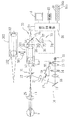
図1は、本実施形態に係る眼底カメラの光学系及び制御系の概略構成図である。光学系は、被験者眼眼底を照明する眼底照明光学系10と、眼底照明光学系10によって照明された眼底反射光を受光して眼底画像を得るための撮像素子を有する撮像光学系30と、被験者眼を固視させるための固視灯呈示光学系70に大別できる。上記光学系は、被験者眼眼底を赤外光にて観察し、可視フラッシュ光を用いて眼底画像を得るために用いられる共に、被験者眼の網膜機能計測に用いられる。
FIG. 1 is a schematic configuration diagram of an optical system and a control system of a fundus camera according to the present embodiment. The optical system includes a fundus illuminating
照明光学系10は、観察照明光学系と撮影照明光学系を有し、ハロゲンランプやLED等の観察用照明光源11、波長750nm以上の近赤外光を透過する赤外フィルタ12、コンデンサレンズ13、フラッシュランプ等の撮影用光源14、リレーレンズ18、ミラー19、リングスリット17、リレーレンズ21、孔あきミラー22、対物レンズ25を有する。
The illumination
なお、前述の照明光学系10は、網膜機能計測のために、被験者眼の眼底に可視刺激光を照射して網膜を刺激する刺激光照射光学系を兼用する。ここで、網膜機能計測を行う場合、例えば、観察光源11が点灯された状態で、照明光学系10の光路から赤外光のみを透過する赤外フィルタ12が退避され、近赤外領域の波長をカットし可視領域の波長のみを透過する可視フィルタ90が照明光学系10の光路に挿入される。ここで、照明光学系10は、赤外フィルタ12と可視フィルタ90とを照明光路上に選択的に挿脱する挿脱機構95を持つ。なお、本実施形態において、可視フィルタ90は、可視光の単色光(例えば、緑色付近(例:λ=568nm付近))のみを透過する特性を持つ。
Note that the illumination
撮影光学系30は、眼底観察光学系と眼底撮影光学系を有し、その光路には、対物レンズ25から順に、穴あきミラー22、被験者眼Eの瞳孔と略共役な位置に配置された撮影絞り31、光軸方向に移動可能なフォーカシングレンズ32(フォーカシングレンズ102)、結像レンズ33(結像レンズ103)、眼底撮影時には挿脱機構39により光路から挿脱可能な跳ね上げミラー34、可視域に感度を有する眼底撮影用の二次元撮像素子35、が配置されている。また、跳ね上げミラー34の反射方向の光路には、赤外光反射・可視光透過の特性を有するダイクロイックミラー37、撮像レンズ36、赤外域に感度を有する観察用二次元撮像素子38が配置されている。なお、フォーカシングレンズ32は、モータを備える移動機構49により光軸方向に移動される。
The photographing
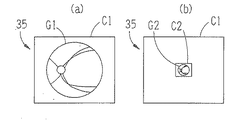
なお、本実施形態に係る眼底撮影光学系30は、被験者眼のカラー眼底画像を得るための撮影光学系と、被験者眼の網膜機能計測用の可視眼底画像を得るための撮影光学系を有し、その用途に応じて撮影光学系を切換可能な構成となっている。より具体的には、通常のカラー眼底画像を取得する場合、図2(a)に示すように、撮像素子35の撮像可能領域C1全体に大きく眼底像G1が撮像されるように、焦点距離が短いフォーカシングレンズ(コリメータレンズ)32と焦点位置の長い結像レンズ33との組み合わせからなる光学ユニット301が撮影光学系30の光路に挿入される。
The fundus photographing
一方、計測用眼底画像を取得する場合、図2(b)に示すように、撮像素子35の撮像可能領域C1に対し小さい撮影範囲C2(例えば、1/5倍)に眼底像G1より小さい眼底像G2(例えば、1/5倍)が撮像されるように、物側焦点距離が長くフォーカシングレンズ(コリメータレンズ)102と像側焦点位置の短い結像レンズ103との組み合わせからなる光学ユニット302が撮影光学系30の光路に挿入される。なお、305は、上記光学ユニット301及び302のいずれかを撮影光学系30の光路に選択的に配置させるために駆動する切換駆動機構である。また、上記構成において、用途に応じて光学系の切換がなされても、被験者眼眼底の撮影範囲自体は同範囲となるように光学設計されているのが好ましい。
On the other hand, when acquiring a fundus image for measurement, as shown in FIG. 2 (b), the fundus is smaller than the fundus image G1 in an imaging range C2 (for example, 1/5 times) smaller than the imageable area C1 of the
以下に、通常のカラー眼底画像を得る場合の光路について説明する。観察用光源11を発した光束は、赤外フィルタ12により赤外光束とされ、コンデンサレンズ13、撮影光源14の透光部、リレーレンズ18を介してミラー19で反射され、リングスリット17を照明する。リングスリット17を透過した光は、リレーレンズ21を経て孔あきミラー22で反射され、対物レンズ25により被験者眼Eの瞳孔付近で一旦収束した後、拡散して被験者眼眼底部を照明する。
In the following, the optical path for obtaining a normal color fundus image will be described. The light beam emitted from the
また、前述のようにして赤外照明された眼底からの反射光は、対物レンズ25、孔あきミラー22の開口部、撮影絞り31、フォーカシングレンズ32、結像レンズ33、跳ね上げミラー34、ダイクロイックミラー37、撮像レンズ36を介して撮像素子38に結像する。なお、撮像素子38の出力は制御部80に入力され、モニタ8には、撮像素子38によって撮像された被験者眼の赤外眼底観察像が表示される。
In addition, the reflected light from the fundus illuminated by infrared rays as described above is transmitted from the objective lens 25, the aperture of the
また、撮影光源14から発せられた可視フラッシュ光は、撮影光源14〜対物レンズ25まで前述の観察用眼底照明光と同様の光路を経て、被験者眼の眼底を照明する。そして、可視光によって照明された眼底からの反射光は、対物レンズ25、孔あきミラー22の開口部、撮影絞り31、フォーカシングレンズ32、結像レンズ33を経て、二次元撮像素子35に結像する。なお、撮像素子35の出力は制御部80に入力され、後述するメモリ(記憶部)85には、撮像素子35によって得られたカラー眼底画像が記憶され、モニタ8にて観察可能となる。
Further, the visible flash light emitted from the
固視灯呈示光学系70は、赤色の光源74、リレーレンズ75を備え、ダイクロイックミラー37を介して跳ね上げミラー34から対物レンズ25までの眼底観察光学系の光路を共用する。
The fixation lamp presentation
固視灯として用いられる固視光源74から発せられた可視光束は、リレーレンズ75、ダイクロイックミラー37、跳ね上げミラー34〜対物レンズ25を通過して被験者眼眼底に集光され、被検者によって固視される。
A visible light beam emitted from a
<制御系> 80は装置全体を制御したり各種演算処理を行う演算制御部(以下、制御部80と省略する)である。演算制御部80には、撮像素子38、撮像素子35、モニタ8、移動機構49、挿脱機構39、各種のスイッチを持つスイッチ部84、メモリ85、切換駆動機構305、挿脱機構95、各光源等が接続されている。なお、スイッチ部84には、眼底像のフォーカス調整を行うためのフォーカス調整スイッチ84a、通常の眼底画像を得るための眼底画像撮影モードと網膜機能計測を行うための網膜機能計測モードとを切り換えるモード切換スイッチ84b等が配置されている。
<Control System> 80 is an arithmetic control unit (hereinafter abbreviated as control unit 80) that controls the entire apparatus and performs various arithmetic processes. The
また、メモリ85には被験者眼の網膜機能を計測するための演算処理プログラムが格納されており、これに基づいて、制御部80は、刺激光に対する網膜反応前後の眼底画像を比較して演算処理することにより網膜機能計測に用いられる変化情報を取得する。
The
なお、本実施形態の眼底カメラは、被験者眼に対して撮影光軸L1を3次元的に移動させる光学系移動機構、被験者眼に対してアライメントを行うための指標投影光学系、等を持つが、周知の構成であり、本発明とは関連が薄いため、説明を省略する。 Note that the fundus camera of the present embodiment has an optical system moving mechanism that three-dimensionally moves the imaging optical axis L1 with respect to the subject's eye, an index projection optical system for performing alignment with the subject's eye, and the like. Since it is a well-known configuration and is not related to the present invention, its description is omitted.
上記のような構成を備える眼底カメラにおいて、通常のカラー眼底画像を取得する場合と、網膜機能計測用の可視眼底画像を取得する場合とに分けて説明する。 In the fundus camera having the above-described configuration, a case where a normal color fundus image is acquired and a case where a visible fundus image for retinal function measurement is acquired will be described separately.
<カラー眼底画像の取得> モード切換スイッチ84bへの操作によって眼底画像撮影モードが設定された場合、制御部80は、眼底観察を行うべく挿脱機構95を駆動制御して、眼底照明光学10の光路に赤外フィルタ12を挿入させ、その光路から可視フィルタ90を退避させる。また、切換駆動機構305の動作により、眼底撮影光学系30の光路にカラー眼底撮影用の光学ユニット301を選択的に挿入する。次に、検者は、図示無きジョイスティックを用いて被験者眼に対して装置を移動させ、赤外光の眼底観察光によって被検者眼Eの眼底に照明光が照射され、所望する眼底画像がモニタ8に表示されるように、アライメントを行う。そして、コントロール部74に設けられたフォーカス調整用スイッチ74aを用いて駆動機構49を駆動させることにより、画像のフォーカス合わせを行う。そして、所望する位置の眼底像がモニタ8に表示された状態において、コントロール部74に設けられた図示なき撮影ボタンを押す。
<Acquisition of Colored Fundus Image> When the fundus image capturing mode is set by operating the
ここで、撮影ボタンが押されると、制御部80は、跳ね上げミラー34を撮影光学系30の光路から退避させ、撮影光源14をストロボ発光させる。これにより、被験者眼眼底が撮影光源14によって照明され、可視照明された被験者眼眼底像が撮像素子35の撮像面に受光される。この場合、図2(a)に示すように、撮像素子35の撮像可能領域C1全体に大きく眼底像G1が撮像され、所定の結像倍率Sからなる被験者眼眼底像が撮像素子35の撮像面に撮影された状態となる。そして、結像倍率Sにて取得されたカラー眼底画像は、メモリ85に記憶されると共に、図3(a)に示すようにモニタ8に表示され、検者によって観察可能となる。ここで、結像倍率Sにて撮影されたカラー眼底画像は、撮像素子35の撮像面全体を用いて得られた眼底画像であり、被験者眼眼底の所定の撮影範囲に対して使用される画素数が多くなるため、解像度の高い鮮明な被験者眼眼底画像を得ることができる。
Here, when the photographing button is pressed, the
<網膜機能計測> 一方、モード切換スイッチ84bへの操作によって網膜機能計測モードが設定された場合、初期状態においては、上記カラー眼底撮影モード同様に、観察光源11が点灯され、赤外フィルタ12、光学ユニット301を用いて、被験者眼の赤外眼底像がモニタ8で観察可能な状態となる。なお、網膜機能の計測を行う場合、被験者眼を暗所にて暗順応させた状態で計測を行うのが好ましい。
<Retina Function Measurement> On the other hand, when the retinal function measurement mode is set by operating the
ここで、所望する位置の眼底像がモニタ8に表示された状態において、前述の撮影ボタンが押されると、制御部80は、機能計測用可視眼底画像を取得するべく、挿脱機構95を駆動制御して、眼底照明光学10の光路に可視フィルタ90を挿入させ、その光路から赤外フィルタ12を退避させる。また、切換駆動機構305を動作させて眼底撮影光学系30の光路に網膜機能計測用の光学ユニット302を選択的に挿入させると共に、駆動機構39を動作させて跳ね上げミラー34を撮影光路から跳ね上げる。ここで、観察光源11から発せられた光束は、可視フィルタ90によって赤外光成分が取り除かれると共に、可視光成分(例えば、緑色成分のみ)が透過され、被験者眼眼底に対して可視光が照射される。
Here, in a state where the fundus image at the desired position is displayed on the monitor 8, when the above-described photographing button is pressed, the
なお、本実施形態では、被験者眼網膜のフォトブリーチング反応を利用して網膜画像の明るさの変化を検出することによって被験者眼網膜の機能計測を行う。すなわち、被験者眼の眼底に可視刺激光(例えば、緑色光)が照射されると、被験者眼の網膜内に含まれているロドプシンと呼ばれる物質が刺激されて退色反応が生じる。そこで、前述のような網膜反応前後における眼底画像の明るさの変化を可視光にて読み取ることにより、この網膜内物質の活動の変化に起因する内因性の信号変化が得ることができる。よって、被検者眼の網膜機能を計測することができる。 In this embodiment, the function of the subject's eye retina is measured by detecting a change in the brightness of the retinal image using the photobleaching reaction of the subject's eye retina. That is, when visible stimulus light (for example, green light) is irradiated to the fundus of the subject's eye, a substance called rhodopsin contained in the retina of the subject's eye is stimulated to cause a fading reaction. Thus, by reading the change in the brightness of the fundus image before and after the retinal reaction as described above with visible light, an intrinsic signal change resulting from the change in the activity of the substance in the retina can be obtained. Therefore, the retinal function of the subject's eye can be measured.
なお、本実施形態において、可視フィルタ90を介して被験者眼に照射される可視刺激光は、機能計測用の眼底画像を取得するための眼底照明光としても用いられる。すなわち、可視刺激光による被験者眼反射光は、対物レンズ25、孔あきミラー22の開口部、撮影絞り31、フォーカシングレンズ102、結像レンズ103を介して撮像素子35に結像する。これにより、観察光源11及び可視フィルタ90によって可視照明された被験者眼眼底像が撮像素子35の撮像面に受光される。この場合、網膜機能計測に適した光量の可視光が被験者眼眼底に照射されるように、観察光源11が発する照明光の光量を眼底観察時と計測用画像取得時とで変化させるようにしてもよい。
In the present embodiment, the visible stimulus light irradiated to the subject's eye via the
この場合、図2(b)に示すように、撮像素子35の撮像可能領域C1に対して小さい眼底像G2が撮像され、所定の結像倍率S2(S2<S1)からなる被験者眼眼底像が撮像素子35の撮像面に撮影された状態となる。
In this case, as shown in FIG. 2B, a small fundus image G2 is captured with respect to the imageable region C1 of the
ここで、制御部80は、撮像素子35からの撮像信号に基づいて結像倍率S2からなる可視眼底画像を経時的に取得することにより機能計測用の可視眼底画像を取得する。より具体的には、制御部80は、観察光源11を連続点灯させ、撮像素子35のフレームレートに応じて連続的に取得される眼底画像を機能計測用眼底画像として逐次メモリ85に記憶させていく。また、観察光源11をフリッカ状に点灯させ、光源11点灯時に撮像素子35から出力される眼底画像を計測用眼底画像として随時メモリ85に記憶させるようにしてもよい。また、観察光源11を1回点灯させたときに刺激前眼底画像を取得し、光源11を消灯後所定時間経過後に、再度光源11を点灯させたときに刺激後眼底画像を取得するようにしてもよい。すなわち、制御部80は、前述のように同一被験者眼から取得された撮影時間(撮影タイミング)の異なる第1の可視眼底画像と第2の可視画像とをメモリ85に記憶する。
Here, the
なお、上記のように網膜刺激用光源及び計測用画像取得用光源として観察光源11(例えば、ハロゲンランプ、LED等)を兼用したため、単位時間あたりの光量が撮影光源14にて眼底画像を得るときの可視フラッシュ光よりも少ない光量にて、被験者眼眼底が可視照明される。このため、微弱な照射光によって被験者眼眼底を照明することができ、被験者眼網膜のブリーチング反応が急速に起こってしまうのを防止でき、網膜反応の連続的な変化を計測することができる。また、可視域から近赤外域までの光を発する光源(ハロゲンランプやLED等)を照明光源として用い、可視フィルタ90と赤外フィルタ12を照明光学系の光路に選択的に挿脱させることにより、赤外眼底画像の取得と計測用可視眼底画像の取得とを効率よく行うことができる。なお、計測画像取得用の照明光学系として、照明光学系10とは別に、計測画像取得用の緑光を被験者眼眼底に向けて照射する照明光学系を設けるようにしてもよい。
Since the observation light source 11 (for example, a halogen lamp, LED, etc.) is also used as the retinal stimulation light source and the measurement image acquisition light source as described above, when the fundus image is obtained by the photographing
ここで、結像倍率S2にて撮影された眼底画像G2は、撮像素子35の撮像面の小さい範囲C2を用いて得られた眼底画像であり、被験者眼眼底の所定の撮影範囲に対して使用される画素数は結像倍率S1の場合に比べて少なくなる。いいかえれば、光学ユニット301挿入時に対して光学ユニット302挿入時の方が眼底反射光に対して集光作用が働くため、一画素当たりの受光効率を上げることができる。このため、網膜刺激による被験者眼眼底の明るさの変化を高いS/N比で検出できる。したがって、網膜刺激による網膜の内因性信号の変化を精度よく検出することが可能となる。
Here, the fundus image G2 photographed at the imaging magnification S2 is a fundus image obtained using a small range C2 of the imaging surface of the
上記のようにして計測用眼底画像の取得が完了したら、制御部80は、演算処理による網膜機能計測に移行する。ここで、制御部80は、メモリ85に記憶された第1可視眼底画像と第2可視眼底画像とを比較し演算処理して変化情報を取得する。この場合、制御部80は、メモリ85に記憶された刺激光に対する網膜反応前後の眼底画像(網膜刺激前後の眼底画像)を用いて、網膜刺激による眼底画像の明るさの変化を各画素毎に求める。例えば、可視光による刺激開始時の眼底画像の明るさに対する刺激開始後所定時間経過後の眼底画像の明るさの変化を各画素毎に求める。明るさの変化は差分や比等求めることによって得られる。そして、制御部80は、得られた明るさの変化情報を各画素に対応させて、図3(b)に示すようにモニタ8に表示する。明るさの変化情報としては、濃淡や高低によって明るさの変化情報を画像として表示する方法や、差分や比の数値情報、この数値情報を網膜機能を評価するための所定の解析プログラムにより演算処理した情報等によって表すことができる。
When the acquisition of the fundus image for measurement is completed as described above, the
以上示したように、上記のような構成によれば、眼底検査に適した鮮明なカラー眼底画像を得ることができると共に、網膜機能の計測を精度よく行うことが可能となる。 As described above, according to the configuration described above, a clear color fundus image suitable for fundus examination can be obtained, and the retinal function can be accurately measured.
なお、以上の説明においては、撮影モードに応じてカラー撮影用光学ユニット301と計測用光学ユニット302を選択的に撮影光学系30の光路に配置させることで、網膜機能計測の場合、通常の眼底画像を取得する場合に対して撮像素子35に眼底像を結像させるときの結像倍率を光学的に切り換える(結像倍率を下げる)ような構成としたが、これに限るものではない。
In the above description, the color fundus
例えば、光路切換が可能な跳ね上げミラーを撮影光学系30に設け、結像倍率S1からなる被験者眼眼底像を撮像するための第1結像光学系及び第1撮像素子を持つ第1光学ユニットを跳ね上げミラーの背面側に配置し、結像倍率S1より倍率の小さい結像倍率S2からなる被験者眼眼底像を撮像するための第2結像光学系及び第2撮像素子を持つ第2光学ユニットを跳ね上げミラーの反射方向に配置するような構成が考えられる。この場合、この跳ね上げミラーが跳ね上げられるときに第1光学ユニットを用いてカラー眼底像を撮影し、跳ね上げミラーが光路内にあるときに第2光学ユニットを用いて計測用眼底像を撮影するような構成が考えられる。すなわち、網膜機能計測の場合、通常の眼底画像を取得する場合に対して、網膜画像計測用の撮像素子に眼底像を結像させるときの結像倍率を光学的に切り換える(結像倍率を下げる)ような構成であればよい。
For example, a flip-up mirror capable of switching the optical path is provided in the photographing
また、以上の説明においては、眼底撮影用撮像素子に結像される結像倍率を光学的に切り換える構成としたが、網膜機能計測の際、通常の眼底画像を取得する場合に対して撮像素子35の感度(ゲイン)を切り換える(感度を上げる)電気的な手段を用いるようにしてもよい。また、結像倍率の切換と感度の切換を併用させるようにしてもよい。 In the above description, the imaging magnification that is imaged on the fundus imaging imaging device is optically switched. However, the imaging device is used for obtaining a normal fundus image when measuring the retinal function. An electrical means for switching the sensitivity (gain) of 35 (increasing the sensitivity) may be used. Further, the switching of the imaging magnification and the switching of the sensitivity may be used in combination.
より具体的には、カラー眼底画像を取得する場合に撮像素子35から出力される撮像信号のゲインを低く設定しておき、機能計測用の眼底画像を取得する場合に撮像素子35から出力される撮像信号のゲインを高めに設定しておく。この場合、カラー眼底画像取得時においては、低いゲインで眼底像を得るため、撮像素子35によるバックグラウンドノイズが少ない状態で撮像信号が得られる。よって、ざらつきの少ない鮮明な眼底画像を得ることができる。一方、機能計測用の眼底画像を取得する場合においては、高いゲインで眼底像を得るため、撮像素子35の1画素あたりの受光効率を高めることができ、網膜の内因性信号の変化を高いS/N比にて得ることが可能である。
More specifically, when a color fundus image is acquired, the gain of the imaging signal output from the
なお、上記ゲイン調整を行うような場合、眼底撮影用撮像素子としてイメージインテンシファイアやエレクトロマルチフライヤー等の比較的高い感度特性を持つ撮像素子を用いるようにしてもよい。なお、撮像ゲインを高くして計測用眼底画像を得る場合、バックグラウンドノイズが増える可能性が高いので、メディアンフィルタや平均化処理等のノイズ除去処理を行うのが好ましい。一方、撮像ゲインを低くして計測用眼底画像を得る場合、バックグラウンドノイズが少ないできるので、被験者眼眼底の生画像に近い眼底画像を得ることができる。この場合、通常の眼底撮影用の撮像素子と計測用眼底画像撮影用の撮像素子を別に設け、計測用眼底画像撮影用の撮像素子として高感度の撮像素子を設けるようにしてもよい。 In the case of performing the gain adjustment, an image sensor having a relatively high sensitivity characteristic such as an image intensifier or an electromultiplier may be used as the fundus imaging image sensor. In addition, when obtaining a fundus image for measurement by increasing the imaging gain, it is highly possible that background noise increases, so it is preferable to perform noise removal processing such as median filtering or averaging processing. On the other hand, when the fundus image for measurement is obtained by lowering the imaging gain, since the background noise can be reduced, a fundus image close to the raw image of the subject's fundus can be obtained. In this case, an imaging element for normal fundus imaging and an imaging element for imaging fundus image imaging may be provided separately, and a high-sensitivity imaging element may be provided as an imaging element for measuring fundus image imaging.
また、上記手法に限るものではなく、第1可視眼底画像と第2可視眼底画像とを比較し演算処理して変化情報を取得する場合、各可視眼底画像として、撮影時間の異なる複数の眼底画像を加算させた加算画像を用いるようにしてもよい。例えば、刺激開始から第1の所定時間が経過する(例えば、0.5s)までに取得された眼底画像同士を加算させた第1可視眼底画像と、第1の所定時間経過後からさらに第2の所定時間が経過する(0.5s〜1.0s)までに取得された眼底画像同士を加算させた第2可視眼底画像とを比較演算するようにしてもよい。 In addition, the present invention is not limited to the above method, and when the first visible fundus image and the second visible fundus image are compared and arithmetic processing is performed to obtain change information, a plurality of fundus images having different shooting times are obtained as each visible fundus image. You may make it use the addition image which added. For example, the first visible fundus image obtained by adding the fundus images acquired until the first predetermined time has elapsed (for example, 0.5 s) from the start of the stimulus, and the second further after the first predetermined time has elapsed. The second visible fundus image obtained by adding the fundus images acquired until the predetermined time elapses (0.5 s to 1.0 s) may be compared and calculated.
また、同じ被験者眼に対してカラー眼底像撮影と網膜機能計測とを同時期に行うような場合、初めに網膜機能計測を行い、後にカラー眼底像撮影を行う。これは、カラー眼底像撮影時にストロボ光源の発光によってブリーチング反応が生じてしまうのを防ぐためである。この場合、得られたカラー眼底像と網膜機能の計測結果とをモニタ8に並列表示させるようにしてもよい。 In addition, when performing color fundus image photographing and retinal function measurement for the same subject eye at the same time, retinal function measurement is performed first, and color fundus image photographing is performed later. This is to prevent a bleaching reaction from occurring due to the light emission of the strobe light source when photographing a color fundus image. In this case, the obtained color fundus image and the measurement result of the retinal function may be displayed on the monitor 8 in parallel.
また、以上の説明においては、観察光源11と可視フィルタ90を用いて被験者眼網膜を可視刺激させるような構成としたが、撮影光源14から発せられる可視フラッシュ光を用いて被験者眼網膜を刺激させるような構成としても良い。この場合、撮影光源14から被験者眼眼底に照射される照射光量を調整することにより、カラー眼底像撮影時の照射光量に対して光量を下げるようにしてもよい。
In the above description, the observation
また、制御部70は、計測用眼底画像としての撮影時間(タイミング)の異なる第1可視眼底画像取得と第2可視眼底画像取得の間に、撮影光源14による刺激光を被験者眼眼底に向けて照射するようにしてもよい。この場合、刺激光照射前後(刺激光照射開始時と,開始後所定時間経過後を含む)の眼底画像を取得する合間に被験者眼眼底に照射される刺激光を眼底照明光として用いることによりカラー眼底画像を取得するようにしてもよい。より具体的には、制御部80は、所定の撮影ボタンからのトリガ信号が入力されたら、観察光源11と可視フィルタ90と光学ユニット302を用いて第1の計測用眼底画像を得ておき、その後撮影光源14と光学ユニット301を用いて(可視フィルタ90は光路から外す)カラー眼底像を得る。そして、撮影光源11の発光によって刺激された被験者眼眼底に対して、観察光源11と可視フィルタ90と光学ユニット302を用いて第2の計測用眼底画像を得る。
Further, the
このようにすれば、網膜機能計測のための網膜刺激とカラー眼底撮影を兼ねることができるため、検者の手間を省くことができると共に、可視光照射による被験者眼への負担を軽減させることができる。 In this way, the retinal stimulation for retinal function measurement can be combined with color fundus photography, so that the labor of the examiner can be saved and the burden on the subject's eye due to the visible light irradiation can be reduced. it can.
8 表示モニタ
10 眼底照明光学系
11 観察光源
12 赤外フィルタ
14 撮影光源
30 眼底撮影光学系
35 撮像素子
84b モード切換スイッチ
85 記憶部
90 可視フィルタ
95 挿脱機構
301 光学ユニット
302 光学ユニット
305 切換駆動機構
DESCRIPTION OF SYMBOLS 8 Display monitor 10 Fundus illumination
Claims (6)
単位時間あたりの光量が前記可視フラッシュ光よりも少ない光量にて被験者眼眼底を可視照明する眼底照明光学系と、
前記眼底照明光学系によって照明された被験者眼眼底からの反射光を受光して眼底画像を得るための撮像素子を有する撮像光学系と、
前記眼底照明光学系及び前記撮像光学系を用いて網膜機能計測用の可視眼底画像を取得する可視眼底画像取得手段と、
該可視眼底画像取得手段によって同一被験者眼から取得された撮影時間の異なる第1の前記可視眼底画像と第2の前記可視眼底画像とを記憶する記憶手段と、
該記憶手段に記憶された前記第1可視眼底画像と第2可視眼底画像とを比較し演算処理して変化情報を取得する変化情報取得手段と、
該変化情報取得手段にて取得された変化情報を表示する表示手段と、
を備えることを特徴とする眼底カメラ。 In a fundus camera that observes the fundus of the subject's eye with infrared light and obtains a color fundus image using visible flash light,
A fundus illumination optical system that illuminates the subject's fundus with a light amount per unit time that is less than the visible flash light; and
An imaging optical system having an imaging element for receiving reflected light from the fundus of the subject's eye illuminated by the fundus illumination optical system and obtaining a fundus image;
Visible fundus image acquisition means for acquiring a visible fundus image for retinal function measurement using the fundus illumination optical system and the imaging optical system;
Storage means for storing the first visible fundus image and the second visible fundus image, which are acquired from the same subject's eye by the visible fundus image acquisition means, and have different shooting times;
Change information acquisition means for comparing the first visible fundus image and the second visible fundus image stored in the storage means and calculating change information to obtain change information;
Display means for displaying change information acquired by the change information acquisition means;
A fundus camera comprising:
前記可視眼底画像取得手段による第1可視眼底画像取得と第2可視眼底画像取得との間に被検者の眼底に向けて刺激光を照射するための刺激光照射手段を備えることを特徴とする眼底カメラ。 The fundus camera of claim 1 comprises:
Stimulation light irradiation means for irradiating stimulation light toward the fundus of the subject between the first visible fundus image acquisition and the second visible fundus image acquisition by the visible fundus image acquisition means is provided. Fundus camera.
前記刺激光照射手段は前記可視フラッシュ光を被験者眼眼底に向けて照射する手段であることを特徴とする眼底カメラ。 The fundus camera of claim 2,
The fundus camera, wherein the stimulating light irradiation means is means for irradiating the visible flash light toward the fundus of the subject's eye.
前記眼底照明光学系は、可視域から近赤外域までの光を発する照明光源と、赤外光のみを透過する赤外フィルタと可視光のみを透過する可視フィルタとを照明光路上に選択的に挿脱する挿脱手段を備えることを特徴とする眼底カメラ。 The fundus camera according to any one of claims 1 to 3,
The fundus illumination optical system selectively includes an illumination light source that emits light from the visible range to the near infrared range, an infrared filter that transmits only infrared light, and a visible filter that transmits only visible light on an illumination optical path. A fundus camera comprising an insertion / removal means for insertion / removal.
通常の眼底画像を得るための眼底撮影モードと網膜機能を計測するための網膜機能計測モードとを切り換えるためのモード切換手段と、
前記挿脱手段を駆動制御する制御手段とを備え、
前記モード切換手段によって網膜機能計測モードが設定されたときは,前記制御手段は前記可視眼底画像取得手段による可視眼底画像取得時に前記眼底照明光学系の照明光路上に前記可視フィルタを挿入し,眼底観察時には赤外フィルタを挿入するように前記挿脱手段を駆動制御することを特徴とする眼底カメラ。 The fundus camera of claim 4 is:
Mode switching means for switching between a fundus imaging mode for obtaining a normal fundus image and a retinal function measurement mode for measuring a retinal function;
Control means for driving and controlling the insertion / removal means,
When the retinal function measurement mode is set by the mode switching unit, the control unit inserts the visible filter into the illumination optical path of the fundus illumination optical system when the visible fundus image is acquired by the visible fundus image acquisition unit, and the fundus A fundus camera characterized by drivingly controlling the insertion / removal means so that an infrared filter is inserted during observation.
通常の眼底画像を取得する場合に対して,前記可視眼底画像取得手段によって前記撮像素子に眼底像を結像させるときの結像倍率を光学的に切り換える切換手段、もしくは通常の眼底画像を取得する場合に対して,前記可視眼底画像取得手段によって可視眼底画像を取得するときの撮像素子の感度を切り換える切換手段、のいずれかを備えることを特徴とする眼底カメラ。 The fundus camera of claim 5,
In contrast to acquiring a normal fundus image, the visible fundus image acquisition unit acquires a switching unit for optically switching the imaging magnification when the fundus image is formed on the image sensor, or acquires a normal fundus image. A fundus camera comprising: a switching unit that switches sensitivity of an image sensor when a visible fundus image is acquired by the visible fundus image acquisition unit.
Priority Applications (2)
| Application Number | Priority Date | Filing Date | Title |
|---|---|---|---|
| JP2007148686A JP2008295971A (en) | 2007-06-04 | 2007-06-04 | Fundus camera |
| US12/155,435 US7658494B2 (en) | 2007-06-04 | 2008-06-04 | Fundus camera |
Applications Claiming Priority (1)
| Application Number | Priority Date | Filing Date | Title |
|---|---|---|---|
| JP2007148686A JP2008295971A (en) | 2007-06-04 | 2007-06-04 | Fundus camera |
Publications (2)
| Publication Number | Publication Date |
|---|---|
| JP2008295971A true JP2008295971A (en) | 2008-12-11 |
| JP2008295971A5 JP2008295971A5 (en) | 2010-07-22 |
Family
ID=40136109
Family Applications (1)
| Application Number | Title | Priority Date | Filing Date |
|---|---|---|---|
| JP2007148686A Ceased JP2008295971A (en) | 2007-06-04 | 2007-06-04 | Fundus camera |
Country Status (2)
| Country | Link |
|---|---|
| US (1) | US7658494B2 (en) |
| JP (1) | JP2008295971A (en) |
Cited By (1)
| Publication number | Priority date | Publication date | Assignee | Title |
|---|---|---|---|---|
| JP2016533865A (en) * | 2013-10-25 | 2016-11-04 | ザ・チルドレンズ・ホスピタル・オブ・フィラデルフィアThe Children’S Hospital Of Philadelphia | Apparatus and method for examining visual function and functional vision by changing brightness level |
Families Citing this family (11)
| Publication number | Priority date | Publication date | Assignee | Title |
|---|---|---|---|---|
| JP5355220B2 (en) * | 2009-05-22 | 2013-11-27 | キヤノン株式会社 | Fundus photographing device |
| US9211064B2 (en) | 2014-02-11 | 2015-12-15 | Welch Allyn, Inc. | Fundus imaging system |
| US9237847B2 (en) | 2014-02-11 | 2016-01-19 | Welch Allyn, Inc. | Ophthalmoscope device |
| US10799115B2 (en) | 2015-02-27 | 2020-10-13 | Welch Allyn, Inc. | Through focus retinal image capturing |
| US11045088B2 (en) | 2015-02-27 | 2021-06-29 | Welch Allyn, Inc. | Through focus retinal image capturing |
| US10136804B2 (en) | 2015-07-24 | 2018-11-27 | Welch Allyn, Inc. | Automatic fundus image capture system |
| US10772495B2 (en) | 2015-11-02 | 2020-09-15 | Welch Allyn, Inc. | Retinal image capturing |
| WO2017120217A1 (en) | 2016-01-07 | 2017-07-13 | Welch Allyn, Inc. | Infrared fundus imaging system |
| US10602926B2 (en) | 2016-09-29 | 2020-03-31 | Welch Allyn, Inc. | Through focus retinal image capturing |
| US11096574B2 (en) | 2018-05-24 | 2021-08-24 | Welch Allyn, Inc. | Retinal image capturing |
| US20220175247A1 (en) * | 2019-04-24 | 2022-06-09 | Topcon Corporation | Ophthalmological device |
Citations (2)
| Publication number | Priority date | Publication date | Assignee | Title |
|---|---|---|---|---|
| JPH04292136A (en) * | 1991-03-20 | 1992-10-16 | Topcon Corp | Opthalmologic photographic device |
| JP2005342107A (en) * | 2004-06-01 | 2005-12-15 | Nidek Co Ltd | Perimeter |
Family Cites Families (7)
| Publication number | Priority date | Publication date | Assignee | Title |
|---|---|---|---|---|
| IL125614A (en) | 1998-07-31 | 2003-01-12 | Amiram Grinvald | System and method for non-invasive imaging of retinal function |
| JP4268861B2 (en) | 2003-11-28 | 2009-05-27 | 株式会社ニデック | Fundus camera |
| JPWO2005084526A1 (en) | 2004-02-20 | 2007-11-29 | 独立行政法人理化学研究所 | Optical measurement method and apparatus for retinal function |
| JP2005342283A (en) | 2004-06-04 | 2005-12-15 | Canon Inc | Ophthalmologic photographing device |
| JP4612396B2 (en) | 2004-11-10 | 2011-01-12 | 株式会社ニデック | Retinal function measuring device |
| JP4600263B2 (en) * | 2005-12-06 | 2010-12-15 | エプソンイメージングデバイス株式会社 | Electro-optical device and electronic apparatus |
| JP5079240B2 (en) | 2006-02-06 | 2012-11-21 | 株式会社ニデック | Retinal function measuring device |
-
2007
- 2007-06-04 JP JP2007148686A patent/JP2008295971A/en not_active Ceased
-
2008
- 2008-06-04 US US12/155,435 patent/US7658494B2/en not_active Expired - Fee Related
Patent Citations (2)
| Publication number | Priority date | Publication date | Assignee | Title |
|---|---|---|---|---|
| JPH04292136A (en) * | 1991-03-20 | 1992-10-16 | Topcon Corp | Opthalmologic photographic device |
| JP2005342107A (en) * | 2004-06-01 | 2005-12-15 | Nidek Co Ltd | Perimeter |
Cited By (1)
| Publication number | Priority date | Publication date | Assignee | Title |
|---|---|---|---|---|
| JP2016533865A (en) * | 2013-10-25 | 2016-11-04 | ザ・チルドレンズ・ホスピタル・オブ・フィラデルフィアThe Children’S Hospital Of Philadelphia | Apparatus and method for examining visual function and functional vision by changing brightness level |
Also Published As
| Publication number | Publication date |
|---|---|
| US7658494B2 (en) | 2010-02-09 |
| US20080316426A1 (en) | 2008-12-25 |
Similar Documents
| Publication | Publication Date | Title |
|---|---|---|
| JP2008295971A (en) | Fundus camera | |
| US20120169995A1 (en) | Method and device for producing high-quality fundus images | |
| JP4458935B2 (en) | Perimeter | |
| JP3723082B2 (en) | Ophthalmic equipment | |
| US8708492B2 (en) | Fundus camera and control method for the fundus camera | |
| WO2012118010A1 (en) | Ophthalmologic imaging apparatus | |
| JP2010259675A (en) | Retinal function measuring apparatus | |
| JP6531369B2 (en) | Fundus imaging device | |
| JP2014079392A (en) | Ophthalmology imaging apparatus | |
| JP2010233978A (en) | Visual performance inspection device | |
| JP5665281B2 (en) | Ophthalmic imaging equipment | |
| JP4914176B2 (en) | Corneal endothelium imaging apparatus and corneal endothelium imaging method | |
| JP4542350B2 (en) | Anterior eye measurement device | |
| JP2014073205A (en) | Ophthalmographic device | |
| JP6255662B2 (en) | Fundus photographing device | |
| JP2005261447A (en) | Ophthalmologic photographing apparatus | |
| JP4738768B2 (en) | Ophthalmic imaging equipment | |
| JP5508140B2 (en) | Fundus imaging apparatus and processing method thereof | |
| JP7355194B2 (en) | fundus imaging device | |
| JP2014161500A (en) | Image processor, ophthalmological photographing apparatus and method, and program | |
| JP5160958B2 (en) | Fundus photographing apparatus and fundus image processing apparatus | |
| JP7029324B2 (en) | Light source control device, ophthalmic device, and light source control method | |
| JP2018019896A (en) | Ocular fundus imaging apparatus | |
| JP6784019B2 (en) | Fundus photography device and information processing program for ophthalmology | |
| JP5963839B2 (en) | Ophthalmic photographing apparatus and image composition method |
Legal Events
| Date | Code | Title | Description |
|---|---|---|---|
| A521 | Request for written amendment filed |
Free format text: JAPANESE INTERMEDIATE CODE: A523 Effective date: 20100603 |
|
| A621 | Written request for application examination |
Free format text: JAPANESE INTERMEDIATE CODE: A621 Effective date: 20100603 |
|
| A977 | Report on retrieval |
Free format text: JAPANESE INTERMEDIATE CODE: A971007 Effective date: 20120307 |
|
| A01 | Written decision to grant a patent or to grant a registration (utility model) |
Free format text: JAPANESE INTERMEDIATE CODE: A01 Effective date: 20120322 |
|
| A045 | Written measure of dismissal of application [lapsed due to lack of payment] |
Free format text: JAPANESE INTERMEDIATE CODE: A045 Effective date: 20120801 |