JP2005342283A - Ophthalmologic photographing device - Google Patents
Ophthalmologic photographing device Download PDFInfo
- Publication number
- JP2005342283A JP2005342283A JP2004166672A JP2004166672A JP2005342283A JP 2005342283 A JP2005342283 A JP 2005342283A JP 2004166672 A JP2004166672 A JP 2004166672A JP 2004166672 A JP2004166672 A JP 2004166672A JP 2005342283 A JP2005342283 A JP 2005342283A
- Authority
- JP
- Japan
- Prior art keywords
- image
- fundus
- imaging
- light
- shooting
- Prior art date
- Legal status (The legal status is an assumption and is not a legal conclusion. Google has not performed a legal analysis and makes no representation as to the accuracy of the status listed.)
- Pending
Links
Images


Classifications
-
- A—HUMAN NECESSITIES
- A61—MEDICAL OR VETERINARY SCIENCE; HYGIENE
- A61B—DIAGNOSIS; SURGERY; IDENTIFICATION
- A61B3/00—Apparatus for testing the eyes; Instruments for examining the eyes
- A61B3/10—Objective types, i.e. instruments for examining the eyes independent of the patients' perceptions or reactions
- A61B3/14—Arrangements specially adapted for eye photography
-
- A—HUMAN NECESSITIES
- A61—MEDICAL OR VETERINARY SCIENCE; HYGIENE
- A61B—DIAGNOSIS; SURGERY; IDENTIFICATION
- A61B3/00—Apparatus for testing the eyes; Instruments for examining the eyes
- A61B3/10—Objective types, i.e. instruments for examining the eyes independent of the patients' perceptions or reactions
- A61B3/12—Objective types, i.e. instruments for examining the eyes independent of the patients' perceptions or reactions for looking at the eye fundus, e.g. ophthalmoscopes
Abstract
Description
本発明は、眼科医院、集団健診等において用いられる眼科撮影装置に関するものである。 The present invention relates to an ophthalmologic photographing apparatus used in ophthalmic clinics, group medical examinations, and the like.
従来から、様々な撮影媒体に記録する無散瞳眼底カメラが知られている。無散瞳眼底カメラは被検者を自然散瞳の状態で赤外光により観察アライメントし、ストロボ光源等が発する可視光の閃光によってカラー眼底像の静止画記録を行う。従って、撮影光が眩しいと被検者の瞳孔は縮瞳するため、続けて撮影する場合には、瞳孔が自然散瞳するまで10分程度の時間待たなければならない。 Conventionally, a non-mydriatic fundus camera that records on various photographing media is known. A non-mydriatic fundus camera observes and aligns the subject with infrared light in a natural mydriatic state, and records a still image of a color fundus image with a flash of visible light emitted from a strobe light source or the like. Accordingly, since the pupil of the subject dilates when the photographing light is dazzling, when photographing continuously, it is necessary to wait for about 10 minutes until the pupil spontaneously dilates.
集団健診の眼底撮影においては、多人数の左右眼を撮影することが求められる。そこで、片眼の撮影が終わり、他眼の撮影まで被検者を待たせておくことは、時間的、スペース的にも効率が悪い。従って、左右眼を連続して撮影できる程度の低光量での撮影が望まれる。 In fundus photography for group medical examination, it is required to photograph a large number of left and right eyes. Therefore, it is inefficient in terms of time and space to wait for the subject to wait until photographing of one eye is completed and photographing of the other eye. Therefore, it is desired to shoot with a light amount that is low enough to continuously shoot the left and right eyes.
近年では、電子記録式のカメラを用いて眼底像を記録する方式が増えてきているが、このようなカメラを用いて少ない照明光量で撮影する場合には、カメラの撮影感度を高く設定して撮影している。 In recent years, there are an increasing number of methods for recording fundus images using electronic recording cameras. However, when shooting with such a camera with a small amount of illumination, the camera's shooting sensitivity should be set high. Shooting.
また、集団健診の画像は専門の読影者が読影する場合が多いが、読影の時間短縮を図るため、ネットワーク回線を使って画像を遠隔地に転送する方式が用いられている。そのためには、画像サイズが大きいと転送に時間がかかり、読影の効率が低下するため、特許文献1のように画像圧縮技術を用いて画像情報の容量を減らす方式が用いられている。また、特許文献2には、眼底像部分だけを切り出して転送する技術が記載されている。
In addition, images of group medical examinations are often read by specialized interpreters, but in order to shorten the time for interpretation, a system is used in which images are transferred to a remote location using a network line. For this purpose, if the image size is large, the transfer takes time and the interpretation efficiency is lowered. Therefore, a method of reducing the volume of image information using an image compression technique as in
しかし上記の従来方法では、撮影感度を高く設定して撮影した眼底像は、暗電流等のノイズも増幅されるため、色むら等が発生し画質が低下する。また、圧縮技術を用いて画像サイズを小さくするには、非可逆圧縮を用いなければならず、画像に独特のパターンが現れたり、色情報が失われたりするため、画質特にコントラストが低下する。 However, in the above-described conventional method, noise such as dark current is amplified in a fundus image captured with a high imaging sensitivity, resulting in color unevenness and image quality. In order to reduce the image size using the compression technique, lossy compression must be used, and a unique pattern appears in the image or color information is lost, so that the image quality, particularly the contrast, is lowered.
医用画像の場合には、加工を施さない生画像(RAWデータ)が求められ、圧縮画像は診断用画像として認められない場合もある。眼底像部分だけを切り出したのでは、画像の形状が円形又は小判型のように特殊になり、一般のビュワソフトでは正しく再生できない。また、小さく結像したことにより、増加してしまった余白部分を取り除くために、モニタに表示する際に拡大して表示しなければならない。 In the case of a medical image, a raw image (RAW data) that is not processed is required, and the compressed image may not be recognized as a diagnostic image. If only the fundus image portion is cut out, the shape of the image becomes special, such as a circle or an oval shape, and cannot be correctly reproduced by general viewer software. Further, in order to remove the blank portion that has increased due to the small image formation, the image must be enlarged when displayed on the monitor.
本発明の目的は、上述の問題点を解消し、変倍に際しても画像劣化のない眼科撮影装置を提供することにある。 An object of the present invention is to provide an ophthalmologic photographing apparatus that eliminates the above-described problems and has no image deterioration even during zooming.
上記目的を達成するための本発明に係る眼科撮影装置は、被検眼眼底像の同一の範囲を撮像素子に異なる結像倍率で結像する撮影光学系と、前記撮像素子に結像した眼底像をデジタル画像データに変換する眼底撮像手段と、前記結像倍率の縮小に連動した光量で照明する眼底照明手段と、前記結像倍率に応じて前記画像データから眼底画像を含む特定領域を切り出して記憶する画像制御手段とを有することを特徴とする。 In order to achieve the above object, an ophthalmologic photographing apparatus according to the present invention includes a photographing optical system that forms the same range of a fundus image to be examined on an imaging element at different imaging magnifications, and a fundus image formed on the imaging element. A fundus imaging means for converting the image into digital image data, a fundus illumination means for illuminating with a light amount linked to the reduction of the imaging magnification, and a specific region including the fundus image is cut out from the image data according to the imaging magnification. And an image control means for storing.
本発明に係る眼科撮影装置によれば、低光量で撮影しサイズの小さな画像が得られ、画像の診断価値を低下させることなく、転送、保存等の利便性を向上することができる。 According to the ophthalmologic photographing apparatus according to the present invention, it is possible to obtain an image with a small size by photographing with a low amount of light, and it is possible to improve convenience such as transfer and storage without reducing the diagnostic value of the image.
本発明を図示の実施例に基づいて詳細に説明する。 The present invention will be described in detail based on the embodiments shown in the drawings.
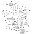
図1は眼底カメラの構成図である。可視光及び赤外光の定常光を発するハロゲンランプ等の観察光源1から対物レンズ2に至る間には、コンデンサレンズ3、可視光を遮断し赤外光を透過する可視カットフィルタ4、閃光を発するストロボ光源5、リング状の開口を有する絞り6、挿入離脱自在に配置された赤外光を遮断する赤外カットフィルタ7、リレーレンズ8、孔あきミラー9が配列されている。
FIG. 1 is a configuration diagram of a fundus camera. Between the
対物レンズ2の後方には、孔あきミラー9の孔部に配置された撮影絞り10、光軸上を移動可能なフォーカスレンズ11、撮影レンズ12、跳ね上げミラー13、絞り14、フィールドレンズ15、択一的に光路中に挿入されるリレーレンズ16a、16b、撮像素子17aを有するデジタルカメラ17が配列され、眼底撮影手段が構成されている。
Behind the
跳ね上げミラー13の反射方向には、視野絞り18、フィールドレンズ19、ミラー20、撮像レンズ21、撮像素子22aを有する撮像手段22が配列され、撮影手段22の出力はモニタ23に接続され、眼底観察手段が構成されている。
In the reflection direction of the flip-
デジタルカメラ17によるデジタル画像データの出力は画像制御回路31に接続され、画像制御回路31はA/D変換器32a、デジタル画像データを記憶する記憶手段である画像メモリ32bを有する画像ボード32、画像制御手段33、ビデオRAM34により構成されている。画像制御手段33には、画像記録手段35が接続され、ビデオRAM34には制御手段36、モニタ37が接続されている。記録手段35には、Mo、MD、DVD、カードメモリ、ハードディスク等の外部より電力供給がなくとも記憶を保持可能な記録媒体Dへの書き込み、又は読み出しを行うドライブ装置が用いられている。
Output of digital image data by the
制御手段36には、撮影スイッチ38、スイッチ39S、39Dを有する撮影モード選択スイッチ39、ストロボ制御回路40が接続されている。ストロボ光源5はストロボ制御回路40により発光を制御され、発光光量はストロボ制御回路40のコンデンサ40aに印加される電圧により制御されるようになっている。
Connected to the control means 36 are a
撮影に際しては、撮影者は被検者を眼底カメラの正面に着座させ、先ず被検眼Eの眼底Erを赤外光で観察しながら、被検眼Eと眼底カメラとの位置合わせを行う。この観察状態において、赤外カットフィルタ7は光路外に待避しており、観察光源1を発した光はコンデンサレンズ3により集光され、可視カットフィルタ4により赤外光のみが透過し、ストロボ光源5、絞り6のリング状開口を通過し、レンズ8を通り、孔あきミラー9の周辺のミラー部により左方に反射され、対物レンズ2、被検眼Eの瞳孔Epを介して眼底Erを照明する。
When photographing, the photographer seats the subject in front of the fundus camera, and first aligns the eye E with the fundus camera while observing the fundus Er of the eye E with infrared light. In this observation state, the
このように、赤外光で照明された眼底Erの像は、再び対物レンズ2、撮影絞り10、フォーカスレンズ11、撮影レンズ12を通り、光路内に配置された跳ね上げミラー13により上方に反射され、視野絞り18の付近に一旦結像し、更にフィールドレンズ19により集光され、ミラー20により左方に反射され、撮像レンズ21により撮像手段22の撮像素子22a上に結像する。撮像手段22において得られた眼底像は、映像信号に変換されモニタ23に表示される。撮影者はこのモニタ23に映った眼底像23aを見ながら、図示しない操作手段を用いて被検眼Eとの位置合わせ、及びフォーカスレンズ11を動かしてピント合わせ及び撮影範囲の確認を行う。
In this way, the image of the fundus Er illuminated with infrared light passes through the
撮影者はモニタ23に表示された眼底像23aを観察し、撮影範囲、位置、ピント合わせが略良好であることを確認した後に、スクリーニング撮影するために、撮影モード選択スイッチ39のスイッチ39Sを操作する。スイッチ39Sへの入力を検知した制御手段36は、リレーレンズ16bに対し縮小結像を行うリレーレンズ16aを光路内に挿入し、ストロボ制御回路40のコンデンサ40aに、リレーレンズ16bを用いて撮影する場合よりも低い電圧を印加し、少ない電荷を充電する。
The photographer observes the
例えば、リレーレンズ16aを用いた場合には、リレーレンズ16bを用いた場合に対し、1/m倍の倍率に結像されるのであれば、発光する光量は1/m2で同等の明るさの眼底像が得られる。そして、撮影スイッチ38を操作し眼底の撮影を行う。
For example, when the
撮影スイッチ38への入力を検知した制御手段36は、先ず赤外光を遮断する赤外カットフィルタ7を光路内に挿入し、デジタルカメラ17の光蓄積を開始し、ストロボ制御回路40に発光信号を送る。発光信号を受けたストロボ制御回路40はストロボ光源5にトリガ信号を送り、コンデンサ40aに蓄えられた電荷を放電し発光する。
The control means 36 that has detected the input to the
ストロボ光源5を発した光束は観察光と同様に、絞り6のリング状開口を通過し、赤外カットフィルタ7により赤外光は除去され、残りの可視光はリレーレンズ8を通り、孔あきミラー9の周辺のミラー部により左方に反射され、対物レンズ2を介して瞳孔Epを介して眼底Erを照明する。
Similar to the observation light, the light beam emitted from the
このように照明された眼底像は、再び対物レンズ2、撮影絞り10、フォーカスレンズ11、撮影レンズ12を通り、跳ね上げられたミラー13の下方を通過し、視野絞り14付近に一旦結像し、フィールドレンズ15により集光され、リレーレンズ16aを介してデジタルカメラ17の撮像素子17aに結像する。デジタルカメラ17は撮像素子17aの全域の画像情報をデジタル画像データに変換し、画像制御回路31に出力する。
The fundus image illuminated in this way passes through the
画像制御回路31の画像制御手段33は次に説明する方法で、予め演算された範囲の画像を切り出し、メモリ32bに記憶する。この画像データは記録手段35により記録媒体Dに保存され、同時にモニタ37に再生される。
The image control means 33 of the
図2は画像の切出領域を演算する方法を示し、例えばデジタルカメラ17の撮像素子17aは、縦2000×3000の600万画素の正方画素であり、有効部の大きさを縦20mm×横30mmとする。
FIG. 2 shows a method for calculating a cutout area of an image. For example, the
観察モードにおける眼底像のイメージサイズの直径を9.6mmとすると、図2に示すように眼底像17bは撮像素子17aの有効撮像領域(20×30)に対し小さく撮像される。ただし、被検眼Eの撮影範囲は撮影者がモニタ23で観察した範囲と等しい。そして、画像制御手段33は撮像範囲を含む矩形領域17cを切り出す。この切出領域17cの計算方法は次のように行うが、矩形である必要はない。
If the diameter of the image size of the fundus image in the observation mode is 9.6 mm, the
撮像素子17aの左上のアドレスを(0,0)とし、縦方向をX、横方向をYとし、画像データのアドレスを(X,Y)と表すと、直径9.6mmの眼底像を含む縦2対横3の相似の矩形領域の大きさは、上下に0.2mmずつの余白を考慮すると、縦10mm×横15mm=1000×1500画素(1画素=20/2000=0.01mm)であり、センタアドレス(光軸)は(1000,1500)となる。
When the upper left address of the
従って、このセンタアドレスを中心として矩形領域を切り出せばよいので、アドレスP1(500,750)、P2(1500,750)、P3(500,2250)、P4(1500,2250)の4点で囲まれた領域を切り出せばよい。 Therefore, the rectangular area may be cut out with the center address as the center, and is surrounded by four points of addresses P1 (500, 750), P2 (1500, 750), P3 (500, 2250), and P4 (1500, 2250). Cut out the area.
画像制御手段33は切り出した領域を記録手段35に記録し、更に必要に応じて通信手段を通じて、外部に画像を転送する。このように画像を矩形状に切り出しているため、外部PC(パーソナルコンピュータ)により汎用のビュアソフトを使用して、撮影画像を見ることも可能である。 The image control means 33 records the cut-out area in the recording means 35, and further transfers the image to the outside through the communication means as necessary. Since the image is cut out in a rectangular shape in this way, it is also possible to view the captured image using general-purpose viewer software with an external PC (personal computer).
このように、撮像素子17aに画像を小さく結像することにより、撮像面での照度を上げることができるため、少ない照明光量で撮影することができる。例えば、リレーレンズ16bを用いた場合のイメージサイズの直径を19.2mmとすると、照明光量は1/4で等しい明るさの眼底像が得られる。これにより、複数枚の連続撮影、両眼の連続撮影が可能になるため、撮影効率を向上することができる。また、少ない領域の画像のみを取り出して保存するため、圧縮等の加工を施さない生画像のままでもメモリを節約でき、記録時間、転送時間を短縮することができる。
Thus, since the illuminance on the imaging surface can be increased by forming a small image on the
このように撮影した画像を観察して、詳細な診断が必要と判断した場合には、撮影モード選択スイッチ39の詳細診断モードを選択するスイッチ39Dを操作する。撮影モード選択スイッチ39のスイッチ39Dへの入力を検知した制御手段36は、リレーレンズ16aを光路外に退避してリレーレンズ16bを挿入し、ストロボ制御回路40を制御し、観察モードの場合よりも多くの光量で被検眼Eを照明できるように、コンデンサ40aの充電電圧を高く設定する。そして、撮影スイッチ38を操作し眼底Erの撮影を行う。
When the photographed image is observed and it is determined that detailed diagnosis is necessary, the
撮影スイッチ38への入力を検知した制御手段36は、先ず赤外カットフィルタ7を光路内に挿入し、デジタルカメラ17の撮像素子17aの光蓄積を開始し、ストロボ制御回路40に発光信号を送る。発光信号を受けたストロボ制御回路40はストロボ光源5にトリガ信号を送り、コンデンサ40aに蓄えられた電荷を放電し発光する。
The control means 36 that has detected the input to the photographing
ストロボ光源5を発した光束は観察光と同様に、絞り6のリング状開口を通過し、赤外カットフィルタ7により赤外光は除去され、残りの可視光はリレーレンズ8を通り、孔あきミラー9の周辺ミラー部により左方に反射され、対物レンズ2を通して被検眼Eの瞳孔Epを介して眼底Erを照明する。
Similar to the observation light, the light beam emitted from the
このように照明された眼底反射像は、再び対物レンズ2、撮影絞り10、フォーカスレンズ11、撮影レンズ12を通り、跳ね上げられたミラー13の下方を通過し、視野絞り14付近に一旦結像し、フィールドレンズ15により集光され、リレーレンズ16bによりデジタルカメラ17の撮像素子17aに結像し、デジタル画像データに変換される。
The fundus reflection image illuminated in this way passes through the
画像制御手段33は眼底像のデジタル画像データをメモリ32bに記憶する。この画像データは記録手段35により記録媒体Dに保存され、モニタ37に再生される。この画像はスクリーニングモードのときよりも大きく表示される。
The image control means 33 stores the digital image data of the fundus image in the
この診断モードにおいては、図3に示すように眼底像17bは撮像素子17a上に大きく結像する。被検眼Eの撮影範囲は、観察モードのときと同様に、撮影者がモニタ23で観察した範囲と等しい。そして、画像制御手段33は画像データの中から特定の領域を切り出すことなく、全ての画像データを記録手段35に記録し、必要に応じて通信手段を通じて外部に画像を転送する。
In this diagnostic mode, as shown in FIG. 3, the
この場合には画像の容量が大きくなるため、記録、通信に時間がかかり、また被検眼Eに照射する光量も大きいため撮影効率は低下するが、高精細な画像が得られるため、精密診断が可能になり診断の精度が向上する。 In this case, since the capacity of the image becomes large, it takes time for recording and communication, and the amount of light applied to the eye E is large, so that the imaging efficiency is reduced, but a high-definition image can be obtained. This makes it possible to improve the accuracy of diagnosis.
実施例1においては、スクリーニングモード、診断モードと2つのモードを設定し、照明光量、撮影倍率、画像の切り出しを設定したが、図4の実施例2に示すように撮影者の必要性に応じ、所望の画像サイズと撮影光量の関係を設定できれば、更に使い勝手は向上する。 In the first embodiment, the screening mode and the diagnostic mode are set, and the illumination light quantity, shooting magnification, and image clipping are set. However, according to the needs of the photographer as shown in the second embodiment of FIG. If the relationship between the desired image size and photographing light quantity can be set, the usability is further improved.
この場合の図1におけるリレーレンズ16a、16bは、ズームレンズ16cに置換され、制御手段36に接続したレンズ位置制御手段41によりズームレンズ16cの倍率を変更できるようにされている。また、撮影モード選択スイッチ39に代ってモード選択スイッチ42が設けられ、照明光量の強弱を選択できるスイッチ42H、42Lが設けられ、更に選択された照明光量の強度と画像サイズが、表示部42a、42bに表示されるようになっている。
In this case, the
制御手段36は選択された発光エネルギを発するようにストロボ制御回路40のコンデンサ40aの充電電圧を制御する。更に、レンズ位置制御手段41を制御すると、ズームレンズ16cのそれぞれのレンズが移動し、撮像面での画像の結像倍率はこれに伴い連続的に変化する。画像制御手段33はこの結像倍率、即ち画像の大きさに応じた切出領域を演算する。そして、この演算結果に基づいて画像を切り出しメモリ32bに記録する。
The control means 36 controls the charging voltage of the
このとき、切出領域P1、P2、P3、P4のアドレスは、眼底像のイメージサイズの直径をd(mm)とし、次のように関数化することができる。 At this time, the addresses of the cutout areas P1, P2, P3, and P4 can be functionalized as follows, with the diameter of the fundus image being d (mm).
眼底像に対し切り出す余白の大きさを片側0.2mmとすると、切出領域の大きさは、縦d+0.4mm、横(d+0.4)×3/2mmとなる。前述のように、画素密度を20/2000=0.01mmとすると、切り出す画素サイズは縦(d+0.4)/0.01画素、横(d+0.4)×3/2/0.01画素となり、センタアドレスは、(1000,1500)となる。 If the size of the margin to be cut out from the fundus image is 0.2 mm on one side, the size of the cut-out area is vertical d + 0.4 mm and horizontal (d + 0.4) × 3/2 mm. As described above, when the pixel density is 20/2000 = 0.01 mm, the pixel size to be cut out is vertical (d + 0.4) /0.01 pixel and horizontal (d + 0.4) × 3/2 / 0.01 pixel. The center address is (1000, 1500).
従って、P1{1000−(d+0.4)/0.01/2,1500−(d+0.4)×3/2/0.01/2}
P2{1000+(d+0.4)/0.01/2,1500−(d+0.4)×3/2/0.01/2}
P3{1000−(d+0.4)/0.01/2,1500+(d+0.4)×3/2/0.01/2}
P4{1000+(d+0.4)/0.01/2,1500+(d+0.4)×3/2/0.01/2}となる。
Therefore, P1 {1000− (d + 0.4) /0.01/2,1500− (d + 0.4) × 3/2 / 0.01 / 2}
P2 {1000+ (d + 0.4) /0.01/2,1500− (d + 0.4) × 3/2 / 0.01 / 2}
P3 {1000− (d + 0.4) /0.01/2,1500+ (d + 0.4) × 3/2 / 0.01 / 2}
P4 {1000+ (d + 0.4) /0.01/2,1500+ (d + 0.4) × 3/2 / 0.01 / 2}.
ただし、アドレスP1が(0,0)より小さくなる場合には、切り出しは行わないものとする。 However, when the address P1 is smaller than (0, 0), the cutout is not performed.
1 観察光源
2 対物レンズ
5 ストロボ光源
9 孔あきミラー
13 跳ね上げミラー
17 デジタルカメラ
17a、22a 撮像素子
22 撮像手段
23、37 モニタ
31 画像制御回路
35 記録手段
36 画像制御回路
38 撮影スイッチ
39、42 撮影モード選択スイッチ
40 ストロボ制御回路
41 レンズ位置制御手段
DESCRIPTION OF
Claims (6)
Priority Applications (6)
| Application Number | Priority Date | Filing Date | Title |
|---|---|---|---|
| JP2004166672A JP2005342283A (en) | 2004-06-04 | 2004-06-04 | Ophthalmologic photographing device |
| US11/144,158 US7354154B2 (en) | 2004-06-04 | 2005-06-02 | Ophthalmic image taking apparatus and ophthalmic image taking method |
| DE602005013718T DE602005013718D1 (en) | 2004-06-04 | 2005-06-02 | Ophthalmic imaging device and ophthalmologic imaging method |
| EP05011942A EP1602324B1 (en) | 2004-06-04 | 2005-06-02 | Ophthalmic image taking apparatus and ophthalmic image taking method |
| CNB2005100760301A CN100387184C (en) | 2004-06-04 | 2005-06-03 | Ophthalmic image taking apparatus and ophthalmic image taking method |
| KR1020050048048A KR100637288B1 (en) | 2004-06-04 | 2005-06-04 | Ophthalmic image taking apparatus and ophthalmic image taking method |
Applications Claiming Priority (1)
| Application Number | Priority Date | Filing Date | Title |
|---|---|---|---|
| JP2004166672A JP2005342283A (en) | 2004-06-04 | 2004-06-04 | Ophthalmologic photographing device |
Related Child Applications (1)
| Application Number | Title | Priority Date | Filing Date |
|---|---|---|---|
| JP2010186064A Division JP5792935B2 (en) | 2010-08-23 | 2010-08-23 | Ophthalmic imaging equipment |
Publications (2)
| Publication Number | Publication Date |
|---|---|
| JP2005342283A true JP2005342283A (en) | 2005-12-15 |
| JP2005342283A5 JP2005342283A5 (en) | 2007-07-12 |
Family
ID=34937184
Family Applications (1)
| Application Number | Title | Priority Date | Filing Date |
|---|---|---|---|
| JP2004166672A Pending JP2005342283A (en) | 2004-06-04 | 2004-06-04 | Ophthalmologic photographing device |
Country Status (6)
| Country | Link |
|---|---|
| US (1) | US7354154B2 (en) |
| EP (1) | EP1602324B1 (en) |
| JP (1) | JP2005342283A (en) |
| KR (1) | KR100637288B1 (en) |
| CN (1) | CN100387184C (en) |
| DE (1) | DE602005013718D1 (en) |
Cited By (1)
| Publication number | Priority date | Publication date | Assignee | Title |
|---|---|---|---|---|
| US7658494B2 (en) | 2007-06-04 | 2010-02-09 | Nidek Co., Ltd | Fundus camera |
Families Citing this family (10)
| Publication number | Priority date | Publication date | Assignee | Title |
|---|---|---|---|---|
| JP4901201B2 (en) * | 2005-12-08 | 2012-03-21 | 興和株式会社 | Fundus image processing method and apparatus |
| CN101566727B (en) * | 2008-04-22 | 2010-12-22 | 深圳市莫廷影像技术有限公司 | Ophthalmonogy probe imaging system |
| CN102370455A (en) * | 2010-08-09 | 2012-03-14 | 明达医学科技股份有限公司 | Eyebase optical image device |
| CN102370456A (en) * | 2010-08-09 | 2012-03-14 | 明达医学科技股份有限公司 | Eyebase optical image device |
| US8398238B1 (en) * | 2011-08-26 | 2013-03-19 | Alcon Lensx, Inc. | Imaging-based guidance system for ophthalmic docking using a location-orientation analysis |
| CN102657515B (en) * | 2012-05-10 | 2014-03-12 | 中国科学院长春光学精密机械与物理研究所 | Alignment light path device applied to retinal imaging system |
| CN102657514B (en) * | 2012-05-10 | 2014-06-18 | 中国科学院长春光学精密机械与物理研究所 | Portable retinal imager |
| JP6270312B2 (en) | 2012-11-09 | 2018-01-31 | キヤノン株式会社 | Ophthalmic apparatus, image processing method, and program |
| CN103499868B (en) * | 2013-10-10 | 2016-05-18 | 山东神戎电子股份有限公司 | The bearing calibration of laser night-vision device synchronous zoom |
| KR20210009196A (en) | 2019-07-16 | 2021-01-26 | 주식회사 유엠아이옵틱스 | Optical Imaging Apparatus for Ophthalmology |
Citations (5)
| Publication number | Priority date | Publication date | Assignee | Title |
|---|---|---|---|---|
| JPS5412195A (en) * | 1977-06-30 | 1979-01-29 | Canon Kk | Ophthalmologic device for correcting amount of light according to variable multiplication |
| JPS5586439A (en) * | 1978-12-22 | 1980-06-30 | Canon Kk | Ophthalmic inspecting device |
| JPH05192299A (en) * | 1992-01-21 | 1993-08-03 | Topcon Corp | Fundus camera |
| JPH0698859A (en) * | 1992-08-04 | 1994-04-12 | Topcon Corp | Ophthalmic image processing system |
| JPH0788088A (en) * | 1993-09-27 | 1995-04-04 | Topcon Corp | Photographing device for oculist |
Family Cites Families (7)
| Publication number | Priority date | Publication date | Assignee | Title |
|---|---|---|---|---|
| US4265518A (en) * | 1977-06-30 | 1981-05-05 | Canon Kabushiki Kaisha | Variable magnification apparatus having illumination compensating ability |
| JP3073510B2 (en) | 1990-07-27 | 2000-08-07 | 株式会社トプコン | Ophthalmic imaging equipment |
| DE4326716B4 (en) * | 1992-08-04 | 2005-03-03 | Kabushiki Kaisha Topcon | Arrangement for processing an ophthalmological image |
| JP3805612B2 (en) * | 2000-10-20 | 2006-08-02 | 株式会社ニデック | Fundus camera |
| EP1210905B1 (en) * | 2000-12-01 | 2007-05-09 | Nidek Co., Ltd. | Fundus camera |
| US7055955B2 (en) * | 2001-02-27 | 2006-06-06 | Canon Kabushiki Kaisha | Eye fundus examination apparatus |
| JP3584246B2 (en) * | 2002-06-17 | 2004-11-04 | キヤノン株式会社 | Ophthalmic imaging device |
-
2004
- 2004-06-04 JP JP2004166672A patent/JP2005342283A/en active Pending
-
2005
- 2005-06-02 US US11/144,158 patent/US7354154B2/en not_active Expired - Fee Related
- 2005-06-02 DE DE602005013718T patent/DE602005013718D1/en active Active
- 2005-06-02 EP EP05011942A patent/EP1602324B1/en not_active Expired - Fee Related
- 2005-06-03 CN CNB2005100760301A patent/CN100387184C/en not_active Expired - Fee Related
- 2005-06-04 KR KR1020050048048A patent/KR100637288B1/en not_active IP Right Cessation
Patent Citations (5)
| Publication number | Priority date | Publication date | Assignee | Title |
|---|---|---|---|---|
| JPS5412195A (en) * | 1977-06-30 | 1979-01-29 | Canon Kk | Ophthalmologic device for correcting amount of light according to variable multiplication |
| JPS5586439A (en) * | 1978-12-22 | 1980-06-30 | Canon Kk | Ophthalmic inspecting device |
| JPH05192299A (en) * | 1992-01-21 | 1993-08-03 | Topcon Corp | Fundus camera |
| JPH0698859A (en) * | 1992-08-04 | 1994-04-12 | Topcon Corp | Ophthalmic image processing system |
| JPH0788088A (en) * | 1993-09-27 | 1995-04-04 | Topcon Corp | Photographing device for oculist |
Cited By (1)
| Publication number | Priority date | Publication date | Assignee | Title |
|---|---|---|---|---|
| US7658494B2 (en) | 2007-06-04 | 2010-02-09 | Nidek Co., Ltd | Fundus camera |
Also Published As
| Publication number | Publication date |
|---|---|
| US20050270485A1 (en) | 2005-12-08 |
| CN1706341A (en) | 2005-12-14 |
| CN100387184C (en) | 2008-05-14 |
| DE602005013718D1 (en) | 2009-05-20 |
| KR100637288B1 (en) | 2006-10-24 |
| EP1602324A1 (en) | 2005-12-07 |
| KR20060048202A (en) | 2006-05-18 |
| EP1602324B1 (en) | 2009-04-08 |
| US7354154B2 (en) | 2008-04-08 |
Similar Documents
| Publication | Publication Date | Title |
|---|---|---|
| KR100637288B1 (en) | Ophthalmic image taking apparatus and ophthalmic image taking method | |
| JP4865257B2 (en) | Fundus photographing apparatus and program | |
| JP3630857B2 (en) | Ophthalmic imaging equipment | |
| JP3584246B2 (en) | Ophthalmic imaging device | |
| JP2005270152A (en) | Ophthalmologic photographing apparatus | |
| JPH09206278A (en) | Ophthalmic picture processing device | |
| JP2003052639A (en) | Ophthalmologic photographing apparatus | |
| JP5792935B2 (en) | Ophthalmic imaging equipment | |
| KR100684299B1 (en) | Ophthalmologic image taking apparatus | |
| JP4731703B2 (en) | Ophthalmic equipment | |
| JP5875567B2 (en) | Ophthalmic imaging apparatus and control method thereof | |
| JP5465210B2 (en) | Fundus photographing device | |
| JP2003204939A (en) | Ophthalmic imaging system | |
| JP2013056222A (en) | Ophthalmic apparatus and conversion method | |
| JP2005124879A (en) | Ocular fundus image processing unit | |
| JP2003230540A (en) | Ophthalmic imaging system | |
| JP2005118465A (en) | Ophthalmologic photographing device and photographing method | |
| JP5084759B2 (en) | Ophthalmic imaging equipment | |
| JP2005087300A (en) | Ophthalmologic photographing apparatus | |
| JP5484419B2 (en) | Ophthalmic apparatus and conversion method | |
| JP2005006926A (en) | Ophthalmologic imaging system | |
| JPH09238906A (en) | Ophthalmologic photographing device | |
| JP2003210407A (en) | Ophthalmologic photographing device | |
| JP2005278747A (en) | Ophthalmologic photography apparatus | |
| JP2005278745A (en) | Ophthalmologic photographing device |
Legal Events
| Date | Code | Title | Description |
|---|---|---|---|
| A521 | Written amendment |
Free format text: JAPANESE INTERMEDIATE CODE: A523 Effective date: 20070525 |
|
| A621 | Written request for application examination |
Free format text: JAPANESE INTERMEDIATE CODE: A621 Effective date: 20070525 |
|
| RD01 | Notification of change of attorney |
Free format text: JAPANESE INTERMEDIATE CODE: A7421 Effective date: 20100218 |
|
| A131 | Notification of reasons for refusal |
Free format text: JAPANESE INTERMEDIATE CODE: A131 Effective date: 20100622 |
|
| RD01 | Notification of change of attorney |
Free format text: JAPANESE INTERMEDIATE CODE: A7421 Effective date: 20100630 |
|
| A521 | Written amendment |
Free format text: JAPANESE INTERMEDIATE CODE: A523 Effective date: 20100823 |
|
| A02 | Decision of refusal |
Free format text: JAPANESE INTERMEDIATE CODE: A02 Effective date: 20110105 |
|
| A521 | Written amendment |
Free format text: JAPANESE INTERMEDIATE CODE: A523 Effective date: 20110405 |
|
| A911 | Transfer to examiner for re-examination before appeal (zenchi) |
Free format text: JAPANESE INTERMEDIATE CODE: A911 Effective date: 20110408 |
|
| A912 | Re-examination (zenchi) completed and case transferred to appeal board |
Free format text: JAPANESE INTERMEDIATE CODE: A912 Effective date: 20110520 |