JP2008290704A - Method for vertical takeoff from and landing on inclined surfaces - Google Patents
Method for vertical takeoff from and landing on inclined surfaces Download PDFInfo
- Publication number
- JP2008290704A JP2008290704A JP2008042051A JP2008042051A JP2008290704A JP 2008290704 A JP2008290704 A JP 2008290704A JP 2008042051 A JP2008042051 A JP 2008042051A JP 2008042051 A JP2008042051 A JP 2008042051A JP 2008290704 A JP2008290704 A JP 2008290704A
- Authority
- JP
- Japan
- Prior art keywords
- inclined surface
- landing
- uav
- unmanned aircraft
- flight control
- Prior art date
- Legal status (The legal status is an assumption and is not a legal conclusion. Google has not performed a legal analysis and makes no representation as to the accuracy of the status listed.)
- Pending
Links
- 238000000034 method Methods 0.000 title claims description 18
- RZVHIXYEVGDQDX-UHFFFAOYSA-N 9,10-anthraquinone Chemical compound C1=CC=C2C(=O)C3=CC=CC=C3C(=O)C2=C1 RZVHIXYEVGDQDX-UHFFFAOYSA-N 0.000 claims abstract description 35
- 230000005484 gravity Effects 0.000 claims description 8
- 230000007246 mechanism Effects 0.000 abstract description 6
- 238000010586 diagram Methods 0.000 description 10
- 238000013500 data storage Methods 0.000 description 3
- 230000007704 transition Effects 0.000 description 3
- 230000008901 benefit Effects 0.000 description 2
- 241000408659 Darpa Species 0.000 description 1
- 241000269799 Perca fluviatilis Species 0.000 description 1
- 230000009286 beneficial effect Effects 0.000 description 1
- 230000000694 effects Effects 0.000 description 1
- 239000000446 fuel Substances 0.000 description 1
- 238000005259 measurement Methods 0.000 description 1
Images


Classifications
-
- B—PERFORMING OPERATIONS; TRANSPORTING
- B64—AIRCRAFT; AVIATION; COSMONAUTICS
- B64C—AEROPLANES; HELICOPTERS
- B64C27/00—Rotorcraft; Rotors peculiar thereto
- B64C27/20—Rotorcraft characterised by having shrouded rotors, e.g. flying platforms
-
- B—PERFORMING OPERATIONS; TRANSPORTING
- B64—AIRCRAFT; AVIATION; COSMONAUTICS
- B64C—AEROPLANES; HELICOPTERS
- B64C39/00—Aircraft not otherwise provided for
- B64C39/02—Aircraft not otherwise provided for characterised by special use
- B64C39/024—Aircraft not otherwise provided for characterised by special use of the remote controlled vehicle type, i.e. RPV
-
- B—PERFORMING OPERATIONS; TRANSPORTING
- B64—AIRCRAFT; AVIATION; COSMONAUTICS
- B64D—EQUIPMENT FOR FITTING IN OR TO AIRCRAFT; FLIGHT SUITS; PARACHUTES; ARRANGEMENTS OR MOUNTING OF POWER PLANTS OR PROPULSION TRANSMISSIONS IN AIRCRAFT
- B64D45/00—Aircraft indicators or protectors not otherwise provided for
- B64D45/04—Landing aids; Safety measures to prevent collision with earth's surface
-
- B—PERFORMING OPERATIONS; TRANSPORTING
- B64—AIRCRAFT; AVIATION; COSMONAUTICS
- B64U—UNMANNED AERIAL VEHICLES [UAV]; EQUIPMENT THEREFOR
- B64U50/00—Propulsion; Power supply
- B64U50/10—Propulsion
- B64U50/13—Propulsion using external fans or propellers
- B64U50/14—Propulsion using external fans or propellers ducted or shrouded
-
- G—PHYSICS
- G05—CONTROLLING; REGULATING
- G05D—SYSTEMS FOR CONTROLLING OR REGULATING NON-ELECTRIC VARIABLES
- G05D1/00—Control of position, course or altitude of land, water, air, or space vehicles, e.g. automatic pilot
- G05D1/04—Control of altitude or depth
- G05D1/06—Rate of change of altitude or depth
- G05D1/0607—Rate of change of altitude or depth specially adapted for aircraft
- G05D1/0653—Rate of change of altitude or depth specially adapted for aircraft during a phase of take-off or landing
-
- G—PHYSICS
- G05—CONTROLLING; REGULATING
- G05D—SYSTEMS FOR CONTROLLING OR REGULATING NON-ELECTRIC VARIABLES
- G05D1/00—Control of position, course or altitude of land, water, air, or space vehicles, e.g. automatic pilot
- G05D1/08—Control of attitude, i.e. control of roll, pitch, or yaw
- G05D1/0808—Control of attitude, i.e. control of roll, pitch, or yaw specially adapted for aircraft
- G05D1/0858—Control of attitude, i.e. control of roll, pitch, or yaw specially adapted for aircraft specially adapted for vertical take-off of aircraft
-
- B—PERFORMING OPERATIONS; TRANSPORTING
- B64—AIRCRAFT; AVIATION; COSMONAUTICS
- B64U—UNMANNED AERIAL VEHICLES [UAV]; EQUIPMENT THEREFOR
- B64U10/00—Type of UAV
- B64U10/10—Rotorcrafts
- B64U10/13—Flying platforms
-
- B—PERFORMING OPERATIONS; TRANSPORTING
- B64—AIRCRAFT; AVIATION; COSMONAUTICS
- B64U—UNMANNED AERIAL VEHICLES [UAV]; EQUIPMENT THEREFOR
- B64U10/00—Type of UAV
- B64U10/20—Vertical take-off and landing [VTOL] aircraft
-
- B—PERFORMING OPERATIONS; TRANSPORTING
- B64—AIRCRAFT; AVIATION; COSMONAUTICS
- B64U—UNMANNED AERIAL VEHICLES [UAV]; EQUIPMENT THEREFOR
- B64U10/00—Type of UAV
- B64U10/80—UAVs characterised by their small size, e.g. micro air vehicles [MAV]
-
- B—PERFORMING OPERATIONS; TRANSPORTING
- B64—AIRCRAFT; AVIATION; COSMONAUTICS
- B64U—UNMANNED AERIAL VEHICLES [UAV]; EQUIPMENT THEREFOR
- B64U30/00—Means for producing lift; Empennages; Arrangements thereof
- B64U30/20—Rotors; Rotor supports
-
- B—PERFORMING OPERATIONS; TRANSPORTING
- B64—AIRCRAFT; AVIATION; COSMONAUTICS
- B64U—UNMANNED AERIAL VEHICLES [UAV]; EQUIPMENT THEREFOR
- B64U30/00—Means for producing lift; Empennages; Arrangements thereof
- B64U30/20—Rotors; Rotor supports
- B64U30/26—Ducted or shrouded rotors
-
- B—PERFORMING OPERATIONS; TRANSPORTING
- B64—AIRCRAFT; AVIATION; COSMONAUTICS
- B64U—UNMANNED AERIAL VEHICLES [UAV]; EQUIPMENT THEREFOR
- B64U70/00—Launching, take-off or landing arrangements
- B64U70/80—Vertical take-off or landing, e.g. using rockets
Abstract
Description
米国政府はDARPAにより裁定された契約番号HR0011−05−C−0043に従って本発明におけるある権利を取得した。本発明は一般に垂直離陸及び着陸に関し、特に、傾斜表面上での垂直離陸及び着陸に関する。 The US Government has acquired certain rights in the present invention in accordance with contract number HR0011-05-C-0043, as determined by DARPA. The present invention relates generally to vertical takeoff and landing, and more particularly to vertical takeoff and landing on an inclined surface.
現在まで、無人航空機(UAV;Unmanned Air Vehicles)は典型的には固定翼航空機であった。しかしながら、他の形式のUAVが軍事及び民間の双方の使用のために現在開発されている。現在開発されている1つの形式のUAVはダクトファン式の垂直離陸及び着陸(VTOL)航空機である。VTOL−UAVは「複雑な」地形として普通に表現される窮屈な都会領域及び郊外領域のような種々の領域において作動することができる。 To date, unmanned air vehicles (UAVs) have typically been fixed wing aircraft. However, other types of UAVs are currently being developed for both military and civilian use. One type of UAV currently being developed is a duct fan vertical take-off and landing (VTOL) aircraft. VTOL-UAV can operate in a variety of areas such as tight urban areas and suburban areas that are commonly expressed as “complex” terrain.
VTOL−UAVは、垂直に発進し、予め計画した飛行計画に沿って飛行し、そして垂直に着陸するためにUAVを一般に必要とする自主的な特務(autonomous missions)を遂行するように設計される。例えば、特務で飛行している間のある時点で、UAVは「高所(perch)及び凝視(stare)」観察を遂行することを期待することができる。高所及び凝視観察では、UAVは垂直に着陸し、(可能ならエンジン停止状態で長期間にわたって)観察を遂行し、垂直に離陸することが必要となる。 The VTOL-UAV is designed to perform autonomous missions that generally require a UAV to launch vertically, fly along a pre-planned flight plan, and land vertically . For example, at some point while flying in a special service, the UAV can be expected to perform “perch and stare” observations. For high altitude and staring observations, the UAV needs to land vertically, perform observations (if possible for long periods with the engine off) and take off vertically.
特務では、VTOL−UAVは整備されていない地面又は航空機のデッキ上で離陸及び着陸を行う必要があることがある。離陸及び着陸表面は平坦でないことがあり、例えば、30度又はそれ以上の大きな角度まで傾斜していることがある。伝統的には、機械的な着陸ギヤ機構は、UAVが傾斜表面上で垂直に離陸及び着陸できるように、UAVを水平にするように設計されていた。不運にも、このような機械的な着陸ギヤ機構は、UAVの耐久性及び飛行性能の双方に対して妥協できるようにするため、複雑で重い。更に、ある機械的な着陸ギヤ機構は10度又はそれ以下の傾斜に限定され、これは、UAVがある地形状態で特務を遂行するのを制限してしまうことがある。 Special services may require the VTOL-UAV to take off and land on ungrounded ground or aircraft decks. The takeoff and landing surface may be uneven, for example, tilted to a large angle of 30 degrees or more. Traditionally, mechanical landing gear mechanisms have been designed to level the UAV so that the UAV can take off and land vertically on an inclined surface. Unfortunately, such a mechanical landing gear mechanism is complex and heavy so that it can compromise both the durability and flight performance of the UAV. In addition, some mechanical landing gear mechanisms are limited to a tilt of 10 degrees or less, which can limit the UAV from performing special duties in certain terrain conditions.
従って、傾斜を補償するための機械的な着陸ギヤ機構を使用せずに、VTOL−UAVが傾斜表面上で垂直に離陸及び着陸できるようにするのが有益である。 Therefore, it would be beneficial to allow the VTOL-UAV to take off and land vertically on an inclined surface without using a mechanical landing gear mechanism to compensate for the inclination.
傾斜表面上で無人航空機を着陸させるための方法が開示される。この方法は傾斜表面の上方で垂直に下降させる工程と、傾斜表面により生じる圧力差を検出する工程と、圧力差により生じる運動に対抗する工程と、無人航空機が傾斜表面に接触する時点を検出する工程と、無人航空機が傾斜表面に接触したときに、無人航空機が傾斜表面上に着陸してしまうまで、無人航空機を回転させる工程とを有する。 A method for landing an unmanned aerial vehicle on an inclined surface is disclosed. The method includes vertically descending over an inclined surface, detecting a pressure difference caused by the inclined surface, combating movement caused by the pressure difference, and detecting when the unmanned aircraft contacts the inclined surface. And rotating the unmanned aircraft until the unmanned aircraft has landed on the inclined surface when the unmanned aircraft contacts the inclined surface.
圧力差により生じる運動に対抗するために、無人航空機の羽根を調整することができる。更に、圧力差により生じる運動に対抗するために無人航空機のスロットルを調整することができる。無人航空機の飛行制御システムは着陸接触状態を検出することができる。無人航空機を回転させるために、無人航空機の羽根を調整することができる。羽根の調整は、無人航空機が傾斜表面に接触したときに生じる運動に対抗するように羽根を動かす工程を有することができる。更に、航空機の下降速度を制御するために無人航空機のスロットルを調整することができる。スロットルの調整は重力に対抗するようにスロットルを増大させる工程を有することができる。 In order to counteract the movement caused by the pressure differential, the blades of the unmanned aircraft can be adjusted. In addition, the unmanned aircraft throttle can be adjusted to counteract the motion caused by the pressure differential. An unmanned aerial vehicle flight control system can detect landing contact conditions. In order to rotate the unmanned aircraft, the blades of the unmanned aircraft can be adjusted. The adjustment of the wings can include moving the wings against the movement that occurs when the unmanned aerial vehicle contacts the inclined surface. Furthermore, the throttle of the unmanned aircraft can be adjusted to control the descending speed of the aircraft. Adjusting the throttle can include increasing the throttle to counteract gravity.
傾斜表面から無人航空機を垂直に離陸させるための方法も開示される。この方法は発進指令を受け取る工程と、姿勢方位を決定する工程と、重力に対抗するように無人航空機の羽根を方位決めする工程と、無人航空機の着陸ギヤを傾斜表面から引き離すように推力を増大させる工程と、傾斜表面から実質上垂直に上昇させる工程とを有する。 A method for vertically taking off an unmanned aerial vehicle from an inclined surface is also disclosed. This method receives the start command, determines the attitude azimuth, orients the unmanned aircraft blades to resist gravity, and increases the thrust to pull the unmanned aircraft landing gear away from the inclined surface. And a step of raising substantially vertically from the inclined surface.
姿勢方位の決定は、無人航空機が傾斜表面上に位置しているか否かを特定することができる。羽根の方位決めは姿勢方位の決定に基づいて羽根を正の角度に調整する工程を含むことができる。方法はまた傾斜表面の上方のある距離へ実質上垂直に上昇させる工程を有することができる。 The determination of the attitude orientation can specify whether or not the unmanned aircraft is located on an inclined surface. The blade orientation determination may include adjusting the blade to a positive angle based on the attitude orientation determination. The method can also include the step of raising substantially vertically to a distance above the inclined surface.
傾斜表面上で垂直に離陸及び着陸させるための方法も開示される。この方法は無人航空機の飛行制御システムにおいて離陸モードを提供する工程を有する。離陸モードは傾斜表面に実質上垂直に最初に上昇させるように無人航空機の少なくとも1つの羽根及び推力を調整する。方法はまた無人航空機の飛行制御システムにおいて着陸モードを提供する工程を有する。着陸モードは、無人航空機が着陸するまで接触地点のまわりで無人航空機を回転させるように、無人航空機が接触地点で傾斜表面に接触したことを検出したときに、無人航空機の少なくとも1つの羽根及び推力を調整する。 A method for vertically taking off and landing on an inclined surface is also disclosed. The method includes providing a takeoff mode in a flight control system for an unmanned aerial vehicle. The takeoff mode adjusts at least one vane and thrust of the unmanned aerial vehicle to first ascend substantially perpendicular to the inclined surface. The method also includes providing a landing mode in the flight control system of the unmanned aerial vehicle. The landing mode is configured to detect at least one vane and thrust of the unmanned aircraft when it detects that the unmanned aircraft has touched the inclined surface at the point of contact so that the unmanned aircraft rotates about the point of contact until the unmanned aircraft has landed. Adjust.
離陸モードは姿勢方位の決定に基づいて羽根を調整することができる。着陸モードは上り坂方向に無人航空機を回転させることができる。更に、着陸モードは接触地点により生じる運動に対抗する。当業者なら、これらの及び他の態様及び利点は、添付図面を適切に参照して以下の詳細な説明を読むことにより、明らかとなろう。更に、この課題を解決するための手段は単なる例であり、特許請求の範囲で規定するような本発明の要旨を限定する意図のものではない。 The take-off mode can adjust the blades based on the determination of the attitude direction. Landing mode can rotate an unmanned aerial vehicle uphill. Furthermore, the landing mode opposes the movement caused by the contact point. These and other aspects and advantages will become apparent to those of ordinary skill in the art by reading the following detailed description, with appropriate reference to the accompanying drawings. Further, the means for solving this problem are merely examples, and are not intended to limit the gist of the present invention as defined in the claims.
添付図面に関連して現時点で好ましい実施の形態を以下に説明するが、種々の図面において、同様の符号は同様の素子を示す。図1は垂直離陸及び着陸(VTOL)無人航空機(UAV)100のブロック線図である。典型的には、UAV100は胴体102と、ダクト104と、制御羽根106と、着陸ギヤ108とを有する。UAV100の重心114は典型的には制御羽根106の上方に位置する。UAV100は他の素子をも含み、任意の特定のVTOL−UAVのデザインに限定されない。例えば、UAV100は有機航空機(OAV)又は小型航空機(MAV)とすることができる。
The presently preferred embodiments are described below with reference to the accompanying drawings, wherein like reference numerals indicate like elements throughout the various views. FIG. 1 is a block diagram of a vertical take-off and landing (VTOL) unmanned aerial vehicle (UAV) 100. Typically, the UAV 100 has a
胴体102は、UAV100の他の素子を収容するハウジングとすることができる。胴体102はUAV100を駆動するエンジン及びエンジンのためのガソリンのような燃料の貯蔵部を収容することができる。胴体102はまた、飛行制御システム110及び道案内システム112のような航空機の作動のための素子を収容することができる。
The
飛行制御システム110は、飛行中のUAV100を制御するためにプロセッサ、データ記憶装置及びモード制御ソフトウエアを有することができる。飛行制御システム110は、道案内システム112及び(又は)UAV100のオペレータから入力を受け取る。入力及び着陸飛行制御モードや離陸飛行制御モードのようなモード形式に応じて、飛行制御システム110は、UAV100の運動を制御するように羽根及びスロットルを調整できる。
The
道案内システム112は、慣性測定センサ、総括位置決め衛星(GPS)センサ、地上レベルセンサ、気圧センサ、磁気計、速度センサ及び加速度計を有することができる。さらに、道案内システム112はプロセッサ及びデータ記憶装置を有することができる。道案内アルゴリズムはデータ記憶装置内に貯蔵することができる。道案内システム112はセンサからデータを受け取ることができ、プロセッサは出力として道案内結果を提供するように道案内アルゴリズムを実行することができる。道案内結果はUAV100の位置、標高、地面からの高さ、姿勢(例えば縦揺れ、横揺れ、偏揺れ)、姿勢率、速度及び(又は)時間の見積もり値とすることができる。
The
ダクト104は、揚力を提供するためにダクト104を通して空気を吸引するファンを有する。ファンは、ダクト104の頂部を通して空気を吸引し、推力を提供するために底部から空気を排出させる。ダクト104とファンとの組み合わせにより生じる推力はUAV100の停空飛翔即ちホバリング及び飛行を可能にするのに十分なほど強力である。制御羽根106はダクト104内に位置するファンの下方に位置することができる。制御羽根106はUAV100のために進路決めする推力を提供する。
Duct 104 has a fan that draws air through
着陸ギヤ108は、飛行していないときのUAV100を支持し、飛行後のUAV100の着陸を可能にする構造体である。着陸ギヤ108は固定の又は活動的な着陸ギヤ機構とすることができる。例えば、着陸ギヤ108は3点支柱又は着陸リングを有することができる。図1に示すように、着陸ギヤ108は3点支柱を有する;しかし、本発明はこの形式の着陸ギヤに限定されない。
着陸飛行制御モード
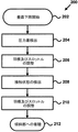
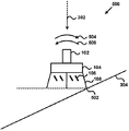
図2は、傾斜部上での垂直着陸のための方法200のフローチャートである。ブロック202において、UAV100は既存の飛行制御モードの下に垂直下降を開始する。図3は傾斜表面304の上方で垂直下降302しているVTOL−UAV100の絵図300である。
The
Landing Flight Control Mode FIG. 2 is a flowchart of a
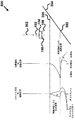
着陸飛行制御モードは、オペレータにより手動で、又は、UAV100が傾斜表面304の上方の所定の高さにあることをUAVの地上レベル(AGL)センサが決定したときに自動的に、開始される。着陸飛行制御モードは、好ましくは飛行制御システム110により実行されるソフトウエアプログラムである。着陸飛行制御モードは道案内システム112から導き出されたデータからUAV100の姿勢方位を監視する。通常の下降においては、UAV100は姿勢306の上方にあり、この場合、面圧がUAV100に影響を及ぼし、下方のダクト104を横切る圧力差は均一である。ブロック204において、UAV100は、図4に示すような圧力差406を検出する。圧力差406は圧力センサを使用せずに姿勢データから推測することができる。代わりに、圧力差406は圧力センサを使用して検出することができる。
The landing flight control mode is initiated either manually by the operator or automatically when the UAV ground level (AGL) sensor determines that the
図4は、傾斜表面304の上方で更に下降するときのVTOL−UAV100の絵図400である。傾斜表面304に向かって下降しているとき、下方のダクト104を横切る圧力差406は均一ではなくなる。飛行制御システム110は、UAV100が体験する圧力差406を検出し、これを補償するように作動できる。
FIG. 4 is a pictorial diagram 400 of the VTOL-
ブロック206において、飛行制御システム110は、羽根160を変調し、スロットルを制御することにより、圧力差406を検出し、これを補償する。飛行制御システム110は、対抗羽根運動402により、面圧によって生じる運動404に対抗する。羽根の偏向は表面の傾斜度に基づき変更することができ、一方、スロットルの設定は航空機の下降速度を維持するような推力に基づく。
In
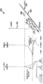
ブロック208において、飛行制御システム110は、図5に示すような着陸接触状態を検出する。図5は、UAV100が接触地点502で傾斜表面304に接触した後のUAV100の絵図500である。傾斜表面304との接触が飛行制御システム110によっては修正できないような方位の変化を生じさせたとき、着陸接触状態の要件が満たされる。この状態は道案内システム112内に含まれる既存の船内センサにより検出することができる。
In
ブロック210において、着陸接触状態が検出された後、羽根106は図5に示すように上り坂方向においてUAV100に回転を与えるために推力を提供するように調整される。対抗羽根運動504は接触地点502により生じる運動506に対抗するように設計される。スロットルはまた、羽根106の遷移中にUAV100上の重力に対抗するのには十分大きいが、傾斜部304から着陸ギヤ108を引き離すほどには大きくない推力を提供するように、図8に示すように変調される。
In
ブロック212において、UAV100は、図6に示すように傾斜表面304上に着陸する。図6はUAV100が傾斜表面304上に着陸した後のUAV100の絵図600である。着陸飛行制御は、すべての着陸ギヤ108が傾斜表面304に接触するまで、接触地点502のまわりでUAV100を制御された割合で枢動させるように羽根106を調整する。この時点で、着陸状態の要件が満たされる。
At block 212, the
着陸状態は、スロットルの連続する減少に拘わらず航空機の姿勢角度率のゼロへの減少として既存の船内センサにより検出することができる。着陸状態のための補助的な条件は、UAV100が航空機の特定の傾き(tip-over) 角度を満たしたことを船内センサが検出することである。着陸状態の要件が満たされたとき、スロットルは、UAV100を完全に着地させるようにゼロ又はアイドル状態に減少する。着陸飛行制御モード手順中の予期されるスロットル設定及び羽根の偏向は図8に示す。
離陸飛行制御モード
図7は、傾斜表面304からの(図6に示すような)垂直離陸602のための方法700のフローチャートである。ブロック702において、UAV100はオペレータから発進指令を受け取る。発進制御を受け取ったとき、離陸飛行制御モードが開始される。離陸飛行制御モードは好ましくは飛行制御システム110により実行されるソフトウエアプログラムである。
Landing conditions can be detected by existing inboard sensors as a decrease in aircraft attitude angle rate to zero, regardless of the continuous decrease in throttle. An auxiliary condition for landing is that the inboard sensor detects that the
Takeoff Flight Control Mode FIG. 7 is a flowchart of a
ブロック704において、離陸飛行制御モードは、例えば、道案内システム112により導き出されたデータからUAV100の姿勢方位を決定する。道案内システム112により測定されるような姿勢は、UAV100が傾斜表面304上に位置していることを表示することができる。
At
ブロック706において、離陸飛行制御モードは、船内センサによる重力の方向(vector)に関する航空機の姿勢の決定に基づき、図6に示すような正の角度に羽根106を方位決めする。スロットルが離陸推力を発生させるように増大したとき、羽根106は、UAV100が傾斜表面304から着陸ギヤ108を実質上同時に引き離すために予め位置するように、航空機の重心114に関する重力に対抗するように方位決めされる。離陸飛行制御モード手順中の予期されるスロットル設定及び羽根の偏向は図9に示す。
At
ブロック708において、UAV100は、最初は離陸表面に実質上垂直に、上昇を開始する。UAV100が傾斜表面304の上方の距離902に達したとき、既存の飛行制御が開始されて、UAV100を、ホバリング又は通常の飛行への遷移のための完全な姿勢へ移行させる。例えば、UAV100は離陸表面の上方の数ダクト直径分の距離内で垂直上昇を開始することができる。
At
UAVの飛行制御システムに離陸及び着陸モードを付加することにより、着陸ギヤはもはや傾斜表面304に対してUAV100を水平にする必要がなくなる。その結果、UAV100は種々の地形に対して一層の特務を履行することができる。UAV100の軍事用及び商業用(例えば警察、消防士、国境警備、森林サービス及び安全保障)の双方の使用はUAV100の改善された多能から有益になることができる。
By adding takeoff and landing modes to the UAV flight control system, the landing gear no longer needs to level the
図示の実施の形態は、単なる例であり、本発明の要旨を限定するものとして受け取るべきではないことを理解すべきである。例えば、本発明は他のVTOL航空機に使用することができる。特許請求の範囲は特記しない限り説明した順番又は素子に限定されるものとして読むべきではない。それ故、特許請求の範囲の要旨及び精神内に入るすべての実施の形態及びその等価物は本発明として請求される。 It should be understood that the illustrated embodiment is merely an example and should not be taken as limiting the scope of the invention. For example, the present invention can be used with other VTOL aircraft. The claims should not be read as limited to the described order or elements unless stated to that effect. Therefore, all embodiments and equivalents thereof falling within the spirit and spirit of the claims are claimed as the invention.
Claims (3)
傾斜表面の上方で垂直に下降させる工程と;
傾斜表面により生じる圧力差を検出する工程と;
圧力差により生じる運動に対抗する工程と;
無人航空機が傾斜表面に接触した時点を検出する工程と;
無人航空機が傾斜表面に接触したときに、無人航空機が傾斜表面に着陸してしまうまで、無人航空機を回転させる工程と;を組み合わせてなる方法。 A method of landing an unmanned aerial vehicle on an inclined surface,
Descending vertically above the inclined surface;
Detecting a pressure difference caused by the inclined surface;
Opposes the movement caused by the pressure difference;
Detecting when the unmanned aerial vehicle contacts the inclined surface;
Rotating the unmanned aircraft until the unmanned aircraft has landed on the inclined surface when the unmanned aircraft contacts the inclined surface.
発進指令を受け取る工程と;
姿勢方位を決定する工程と;
重力に対抗するように無人航空機の羽根を方位決めする工程と;
傾斜表面から無人航空機の着陸ギヤを引き離すように推力を増大させる工程と;
傾斜表面から実質上垂直に上昇させる工程と;を組み合わせてなる方法。 A method of vertically taking an unmanned aircraft from an inclined surface,
Receiving a start command;
Determining a posture orientation;
Orienting the unmanned aerial vehicle's blades to oppose gravity;
Increasing the thrust so as to disengage the landing gear of the unmanned aircraft from the inclined surface;
And a step of raising substantially vertically from the inclined surface.
傾斜表面に対して実質上垂直に最初に上昇するように無人航空機の少なくとも1つの羽根及び推力を調整するような離陸モードを、無人航空機の飛行制御システムに提供する工程と;
無人航空機が着陸してしまうまで、接触地点のまわりで無人航空機を回転させるように、無人航空機が接触地点で傾斜表面に接触してしまったことを検出したときに、無人航空機の少なくとも1つの羽根及び推力を調整するような着陸モードを、無人航空機の飛行制御システムに提供する工程と;を有することを特徴とする方法。 A method for vertical takeoff and landing on an inclined surface, comprising:
Providing the unmanned aircraft flight control system with a takeoff mode that adjusts at least one vane and thrust of the unmanned aerial vehicle to first ascend substantially perpendicular to the inclined surface;
At least one blade of the unmanned aircraft when it detects that the unmanned aircraft has touched the inclined surface at the point of contact, such that the unmanned aircraft rotates about the point of contact until the unmanned aircraft has landed And providing a landing mode for adjusting the thrust to the flight control system of an unmanned aerial vehicle.
Applications Claiming Priority (1)
| Application Number | Priority Date | Filing Date | Title |
|---|---|---|---|
| US11/752,497 US7871044B2 (en) | 2007-05-23 | 2007-05-23 | Method for vertical takeoff from and landing on inclined surfaces |
Publications (2)
| Publication Number | Publication Date |
|---|---|
| JP2008290704A true JP2008290704A (en) | 2008-12-04 |
| JP2008290704A5 JP2008290704A5 (en) | 2011-04-07 |
Family
ID=39561797
Family Applications (1)
| Application Number | Title | Priority Date | Filing Date |
|---|---|---|---|
| JP2008042051A Pending JP2008290704A (en) | 2007-05-23 | 2008-02-22 | Method for vertical takeoff from and landing on inclined surfaces |
Country Status (3)
| Country | Link |
|---|---|
| US (2) | US7871044B2 (en) |
| EP (1) | EP1995174A3 (en) |
| JP (1) | JP2008290704A (en) |
Cited By (11)
| Publication number | Priority date | Publication date | Assignee | Title |
|---|---|---|---|---|
| JP2011230756A (en) * | 2010-04-27 | 2011-11-17 | Honeywell Internatl Inc | Ground proximity sensor |
| WO2014068982A1 (en) * | 2012-10-31 | 2014-05-08 | 国立大学法人徳島大学 | Conveyance device and control method for flight vehicle |
| KR101447809B1 (en) | 2013-03-22 | 2014-10-08 | 김명호 | Aerial Vehicle With Mltipurpose Grip Type Taking Off an Landing Devic |
| CN104330071A (en) * | 2014-10-14 | 2015-02-04 | 南昌航空大学 | Pre-detection method for controlling stationary takeoff of small unmanned helicopter |
| JP2016043927A (en) * | 2014-08-26 | 2016-04-04 | パロット | Method for dynamically controlling unmanned aircraft of rotor blade in throw start |
| KR20160125589A (en) * | 2015-04-21 | 2016-11-01 | 순천대학교 산학협력단 | Apparatus for attitude stabilization of small unmanned aerial vehicle |
| JP2017526566A (en) * | 2014-06-26 | 2017-09-14 | アマゾン テクノロジーズ インコーポレイテッド | Surface detection using ground effect in unmanned aerial vehicles |
| WO2019168079A1 (en) * | 2018-02-28 | 2019-09-06 | 株式会社ナイルワークス | Agricultural drone having improved safety |
| JP2020131779A (en) * | 2019-02-14 | 2020-08-31 | 株式会社Ihi | Flight vehicle |
| US10817000B2 (en) | 2016-09-13 | 2020-10-27 | Fujitsu Limited | Unmanned aerial vehicle and control method of unmanned aerial vehicle |
| WO2021053929A1 (en) * | 2019-09-17 | 2021-03-25 | ソニー株式会社 | Aerial vehicle, control method and program |
Families Citing this family (32)
| Publication number | Priority date | Publication date | Assignee | Title |
|---|---|---|---|---|
| US8200375B2 (en) | 2008-02-12 | 2012-06-12 | Stuckman Katherine C | Radio controlled aircraft, remote controller and methods for use therewith |
| US8878111B2 (en) | 2009-02-24 | 2014-11-04 | Blue Origin, Llc | Bidirectional control surfaces for use with high speed vehicles, and associated systems and methods |
| US8386095B2 (en) * | 2009-04-02 | 2013-02-26 | Honeywell International Inc. | Performing corrective action on unmanned aerial vehicle using one axis of three-axis magnetometer |
| US20100302359A1 (en) | 2009-06-01 | 2010-12-02 | Honeywell International Inc. | Unmanned Aerial Vehicle Communication |
| FR2973335B1 (en) * | 2011-03-29 | 2013-04-19 | Inst Superieur De L Aeronautique Et De L Espace | MICRO / NANO REMOTE CONTROL VEHICLE COMPRISING A SYSTEM FOR FLOOR, VERTICAL TAKEOFF AND LANDING |
| US9547991B2 (en) | 2013-05-23 | 2017-01-17 | Honeywell International Inc. | Aircraft precision approach and shipboard landing control system and method |
| CN103543744B (en) * | 2013-09-10 | 2016-04-27 | 江苏省地质勘查技术院 | A kind of method that unmanned airship airborne magnetic survey line of flight is arranged |
| EP2902319B1 (en) | 2014-01-30 | 2019-06-26 | The Boeing Company | Unmanned aerial vehicle |
| CN103869817A (en) * | 2014-03-03 | 2014-06-18 | 东南大学 | Vertical take-off and landing control method for quad-tilt-rotor unmanned aerial vehicle |
| CN106444795B (en) * | 2014-03-27 | 2019-12-20 | 深圳市大疆创新科技有限公司 | Method and system for assisting take-off of movable object |
| US9033276B1 (en) * | 2015-01-07 | 2015-05-19 | TLL Associates | Telescoping landing leg system |
| TW201643579A (en) * | 2015-06-15 | 2016-12-16 | 鴻海精密工業股份有限公司 | System and method for automatically driving UAV |
| CN105059558B (en) * | 2015-07-16 | 2018-02-02 | 珠海云洲智能科技有限公司 | Unmanned boat-carrying unmanned plane landing system |
| US9448562B1 (en) * | 2015-08-18 | 2016-09-20 | Skycatch, Inc. | Utilizing acceleration information for precision landing of unmanned aerial vehicles |
| US9513635B1 (en) * | 2015-12-30 | 2016-12-06 | Unmanned Innovation, Inc. | Unmanned aerial vehicle inspection system |
| US9740200B2 (en) | 2015-12-30 | 2017-08-22 | Unmanned Innovation, Inc. | Unmanned aerial vehicle inspection system |
| US10083616B2 (en) | 2015-12-31 | 2018-09-25 | Unmanned Innovation, Inc. | Unmanned aerial vehicle rooftop inspection system |
| CN105480413B (en) * | 2016-02-03 | 2019-01-22 | 英华达(上海)科技有限公司 | Unmanned gyroplane and the flying method for controlling unmanned gyroplane |
| US9994307B2 (en) * | 2016-03-25 | 2018-06-12 | The United States Of America As Represented By Secretary Of The Navy | Vertical take-off-and-landing unmanned aerial vehicle system capable of landing on uneven or sloped terrain |
| US11029352B2 (en) | 2016-05-18 | 2021-06-08 | Skydio, Inc. | Unmanned aerial vehicle electromagnetic avoidance and utilization system |
| EP3464069A4 (en) * | 2016-06-01 | 2019-12-04 | Blue Origin, LLC | Severe weather agility thrusters, and associated systems and methods |
| CN105974931B (en) * | 2016-06-30 | 2019-04-09 | 西安电子科技大学 | A kind of display system for UAV Landing display instrument |
| CN106647785B (en) * | 2016-11-16 | 2020-07-14 | 深圳市元征科技股份有限公司 | Unmanned aerial vehicle parking apron control method and device |
| KR101867737B1 (en) * | 2016-12-23 | 2018-06-15 | 주식회사 포스코 | Drone for detecting and protecting corrsion of structure |
| WO2018125942A1 (en) | 2016-12-28 | 2018-07-05 | Blue Origin, Llc | Vertical landing systems for space vehicles and associated methods |
| US10099802B2 (en) | 2017-02-14 | 2018-10-16 | Honeywell International Inc. | Methods and systems to detect and alert a dynamic rollover condition for an aircraft |
| CN108873930B (en) * | 2018-05-31 | 2021-09-10 | 苏州市启献智能科技有限公司 | Unmanned aerial vehicle taking-off and landing method and system based on mobile platform |
| US10625876B2 (en) * | 2018-08-08 | 2020-04-21 | Aurora Flight Sciences Corporation | Aircraft landing systems and methods for monitoring a vertical landing of an aircraft |
| CN109634296A (en) * | 2018-12-18 | 2019-04-16 | 南京航空航天大学 | Small drone catapult-assisted take-off control system and method based on the robust theory of servomechanism |
| WO2020158136A1 (en) * | 2019-02-01 | 2020-08-06 | パナソニックIpマネジメント株式会社 | Unmanned aerial vehicle, information processing method, and program |
| IL302562A (en) * | 2020-11-30 | 2023-07-01 | Efix Aviation Ltd | Rotorcraft |
| WO2022226932A1 (en) * | 2021-04-29 | 2022-11-03 | 深圳市大疆创新科技有限公司 | Unmanned aerial vehicle |
Citations (1)
| Publication number | Priority date | Publication date | Assignee | Title |
|---|---|---|---|---|
| JPH11115896A (en) * | 1997-10-17 | 1999-04-27 | Komatsu Ltd | Unmanned and freely controlled flying body with low speed |
Family Cites Families (10)
| Publication number | Priority date | Publication date | Assignee | Title |
|---|---|---|---|---|
| FR1389617A (en) * | 1964-01-09 | 1965-02-19 | Nord Aviation | Unmanned flying machine |
| US3857533A (en) * | 1974-01-28 | 1974-12-31 | S Mason | Helicopter self-leveling landing gear |
| US4062507A (en) * | 1977-02-03 | 1977-12-13 | Felder Donald W | Slope landing compensator system |
| EP0752634A1 (en) | 1995-07-07 | 1997-01-08 | Sacom Co., Ltd | Apparatus for controlling the attitude of a radio-controlled helicopter |
| FR2758790B1 (en) * | 1997-01-27 | 1999-05-07 | Sci Chaneac Et Fils | IMPROVEMENT OF A VERTICAL TAKE OFF AIRCRAFT |
| US6604706B1 (en) | 1998-08-27 | 2003-08-12 | Nicolae Bostan | Gyrostabilized self propelled aircraft |
| IL138695A (en) | 2000-09-26 | 2004-08-31 | Rafael Armament Dev Authority | Unmanned mobile device |
| US7032861B2 (en) | 2002-01-07 | 2006-04-25 | Sanders Jr John K | Quiet vertical takeoff and landing aircraft using ducted, magnetic induction air-impeller rotors |
| WO2006069291A2 (en) * | 2004-12-22 | 2006-06-29 | Aurora Flight Sciences Corporation | System and method for utilizing stored electrical energy for vtol aircraft thrust enhancement and attitude control |
| US7946528B2 (en) * | 2005-04-15 | 2011-05-24 | Urban Aeronautics, Ltd. | Flight control system especially suited for VTOL vehicles |
-
2007
- 2007-05-23 US US11/752,497 patent/US7871044B2/en not_active Expired - Fee Related
-
2008
- 2008-02-21 EP EP08101858.2A patent/EP1995174A3/en not_active Withdrawn
- 2008-02-22 JP JP2008042051A patent/JP2008290704A/en active Pending
-
2010
- 2010-11-18 US US12/949,410 patent/US8141823B2/en not_active Expired - Fee Related
Patent Citations (1)
| Publication number | Priority date | Publication date | Assignee | Title |
|---|---|---|---|---|
| JPH11115896A (en) * | 1997-10-17 | 1999-04-27 | Komatsu Ltd | Unmanned and freely controlled flying body with low speed |
Cited By (20)
| Publication number | Priority date | Publication date | Assignee | Title |
|---|---|---|---|---|
| JP2011230756A (en) * | 2010-04-27 | 2011-11-17 | Honeywell Internatl Inc | Ground proximity sensor |
| WO2014068982A1 (en) * | 2012-10-31 | 2014-05-08 | 国立大学法人徳島大学 | Conveyance device and control method for flight vehicle |
| JPWO2014068982A1 (en) * | 2012-10-31 | 2016-09-08 | 国立大学法人徳島大学 | Conveying apparatus and flying object control method |
| KR101447809B1 (en) | 2013-03-22 | 2014-10-08 | 김명호 | Aerial Vehicle With Mltipurpose Grip Type Taking Off an Landing Devic |
| US10410527B2 (en) | 2014-06-26 | 2019-09-10 | Amazon Technologies, Inc. | Ground effect based surface sensing using propellers in automated aerial vehicles |
| US10984663B2 (en) | 2014-06-26 | 2021-04-20 | Amazon Technologies, Inc. | Ground effect based surface sensing utilized with other sensing technologies in automated aerial vehicles |
| JP2017526566A (en) * | 2014-06-26 | 2017-09-14 | アマゾン テクノロジーズ インコーポレイテッド | Surface detection using ground effect in unmanned aerial vehicles |
| US9934694B2 (en) | 2014-06-26 | 2018-04-03 | Amazon Technologies, Inc. | Ground effect based surface sensing using multiple propellers in automated aerial vehicles |
| JP2016043927A (en) * | 2014-08-26 | 2016-04-04 | パロット | Method for dynamically controlling unmanned aircraft of rotor blade in throw start |
| CN104330071A (en) * | 2014-10-14 | 2015-02-04 | 南昌航空大学 | Pre-detection method for controlling stationary takeoff of small unmanned helicopter |
| CN104330071B (en) * | 2014-10-14 | 2016-09-14 | 南昌航空大学 | A kind of control the pre-detection method that small-sized depopulated helicopter steadily takes off |
| KR101872295B1 (en) * | 2015-04-21 | 2018-06-29 | 순천대학교 산학협력단 | Apparatus for attitude stabilization of small unmanned aerial vehicle |
| KR20160125589A (en) * | 2015-04-21 | 2016-11-01 | 순천대학교 산학협력단 | Apparatus for attitude stabilization of small unmanned aerial vehicle |
| US10817000B2 (en) | 2016-09-13 | 2020-10-27 | Fujitsu Limited | Unmanned aerial vehicle and control method of unmanned aerial vehicle |
| WO2019168079A1 (en) * | 2018-02-28 | 2019-09-06 | 株式会社ナイルワークス | Agricultural drone having improved safety |
| JPWO2019168079A1 (en) * | 2018-02-28 | 2020-08-06 | 株式会社ナイルワークス | Agricultural drone with improved safety |
| JP2020131779A (en) * | 2019-02-14 | 2020-08-31 | 株式会社Ihi | Flight vehicle |
| JP7196668B2 (en) | 2019-02-14 | 2022-12-27 | 株式会社Ihi | flying object |
| WO2021053929A1 (en) * | 2019-09-17 | 2021-03-25 | ソニー株式会社 | Aerial vehicle, control method and program |
| US20220289376A1 (en) * | 2019-09-17 | 2022-09-15 | Sony Group Corporation | Flying body, control method, and program |
Also Published As
| Publication number | Publication date |
|---|---|
| EP1995174A3 (en) | 2013-04-24 |
| US7871044B2 (en) | 2011-01-18 |
| US20100012776A1 (en) | 2010-01-21 |
| US20110057075A1 (en) | 2011-03-10 |
| EP1995174A2 (en) | 2008-11-26 |
| US8141823B2 (en) | 2012-03-27 |
Similar Documents
| Publication | Publication Date | Title |
|---|---|---|
| JP2008290704A (en) | Method for vertical takeoff from and landing on inclined surfaces | |
| US10474167B2 (en) | System, a method and a computer program product for maneuvering of an air vehicle with tiltable propulsion unit | |
| US9540100B2 (en) | System, a method and a computer program product for maneuvering of an air vehicle | |
| US6604706B1 (en) | Gyrostabilized self propelled aircraft | |
| US10850836B2 (en) | Spherical VTOL aerial vehicle | |
| US20180354623A1 (en) | Multi-rotor aerial vehicle with single arm failure redundancy | |
| NL2017971B1 (en) | Unmanned aerial vehicle | |
| JP2010241409A (en) | Performing corrective action on unmanned aerial vehicle using one axis of three-axis magnetometer | |
| JP2010168034A (en) | Alternative method of ducted fan uav control system | |
| US11479353B2 (en) | Distributed elevon systems for tailsitting biplane aircraft | |
| US11650604B2 (en) | Yaw control systems for tailsitting biplane aircraft | |
| CN115016514A (en) | Full-autonomous flight control method for takeoff, cruise and landing of bionic flapping wing aircraft | |
| US11858626B2 (en) | Autonomous air vehicle delivery system incorporating deployment | |
| AU2020364319B2 (en) | Contingent use of commanded speed in lieu of sensed airspeed to inform flight control decisions | |
| JP2008201183A (en) | Attitude controlling device | |
| JP3231301U (en) | Unmanned aerial vehicle | |
| JP2019064581A (en) | Rotor craft | |
| JP2019077207A (en) | Rotary wing aircraft | |
| US11479354B2 (en) | Thrust vectoring coaxial rotor systems for aircraft | |
| WO2020115934A1 (en) | Rotary wing aircraft | |
| JP2019043394A (en) | Rotary wing aircraft | |
| NL1040979B1 (en) | Air vehicle. | |
| Pelletier et al. | Autonomous navigation and control functions of the CL-327 VTOL UAV |
Legal Events
| Date | Code | Title | Description |
|---|---|---|---|
| A521 | Request for written amendment filed |
Free format text: JAPANESE INTERMEDIATE CODE: A523 Effective date: 20110221 |
|
| A621 | Written request for application examination |
Free format text: JAPANESE INTERMEDIATE CODE: A621 Effective date: 20110221 |
|
| RD04 | Notification of resignation of power of attorney |
Free format text: JAPANESE INTERMEDIATE CODE: A7424 Effective date: 20110912 |
|
| A977 | Report on retrieval |
Free format text: JAPANESE INTERMEDIATE CODE: A971007 Effective date: 20121115 |
|
| A131 | Notification of reasons for refusal |
Free format text: JAPANESE INTERMEDIATE CODE: A131 Effective date: 20121126 |
|
| A601 | Written request for extension of time |
Free format text: JAPANESE INTERMEDIATE CODE: A601 Effective date: 20130225 |
|
| A602 | Written permission of extension of time |
Free format text: JAPANESE INTERMEDIATE CODE: A602 Effective date: 20130228 |
|
| A601 | Written request for extension of time |
Free format text: JAPANESE INTERMEDIATE CODE: A601 Effective date: 20130325 |
|
| A602 | Written permission of extension of time |
Free format text: JAPANESE INTERMEDIATE CODE: A602 Effective date: 20130328 |
|
| A601 | Written request for extension of time |
Free format text: JAPANESE INTERMEDIATE CODE: A601 Effective date: 20130426 |
|
| A602 | Written permission of extension of time |
Free format text: JAPANESE INTERMEDIATE CODE: A602 Effective date: 20130502 |
|
| A521 | Request for written amendment filed |
Free format text: JAPANESE INTERMEDIATE CODE: A523 Effective date: 20130524 |
|
| A131 | Notification of reasons for refusal |
Free format text: JAPANESE INTERMEDIATE CODE: A131 Effective date: 20131129 |
|
| A02 | Decision of refusal |
Free format text: JAPANESE INTERMEDIATE CODE: A02 Effective date: 20140430 |