EP1995174A2 - Method for vertical takeoff from and landing on inclined surfaces - Google Patents
Method for vertical takeoff from and landing on inclined surfaces Download PDFInfo
- Publication number
- EP1995174A2 EP1995174A2 EP08101858A EP08101858A EP1995174A2 EP 1995174 A2 EP1995174 A2 EP 1995174A2 EP 08101858 A EP08101858 A EP 08101858A EP 08101858 A EP08101858 A EP 08101858A EP 1995174 A2 EP1995174 A2 EP 1995174A2
- Authority
- EP
- European Patent Office
- Prior art keywords
- air vehicle
- unmanned air
- inclined surface
- landing
- uav
- Prior art date
- Legal status (The legal status is an assumption and is not a legal conclusion. Google has not performed a legal analysis and makes no representation as to the accuracy of the status listed.)
- Withdrawn
Links
- 238000000034 method Methods 0.000 title claims description 23
- RZVHIXYEVGDQDX-UHFFFAOYSA-N 9,10-anthraquinone Chemical compound C1=CC=C2C(=O)C3=CC=CC=C3C(=O)C2=C1 RZVHIXYEVGDQDX-UHFFFAOYSA-N 0.000 claims abstract description 35
- 230000001174 ascending effect Effects 0.000 claims description 6
- 230000005484 gravity Effects 0.000 claims description 5
- 230000007246 mechanism Effects 0.000 abstract description 6
- 238000010586 diagram Methods 0.000 description 10
- 238000013500 data storage Methods 0.000 description 3
- 241000269799 Perca fluviatilis Species 0.000 description 2
- 230000008901 benefit Effects 0.000 description 2
- 230000007704 transition Effects 0.000 description 2
- 241000408659 Darpa Species 0.000 description 1
- 230000009286 beneficial effect Effects 0.000 description 1
- 230000008859 change Effects 0.000 description 1
- 230000000694 effects Effects 0.000 description 1
- 239000000446 fuel Substances 0.000 description 1
- 238000005259 measurement Methods 0.000 description 1
- 230000009467 reduction Effects 0.000 description 1
Images


Classifications
-
- B—PERFORMING OPERATIONS; TRANSPORTING
- B64—AIRCRAFT; AVIATION; COSMONAUTICS
- B64D—EQUIPMENT FOR FITTING IN OR TO AIRCRAFT; FLIGHT SUITS; PARACHUTES; ARRANGEMENT OR MOUNTING OF POWER PLANTS OR PROPULSION TRANSMISSIONS IN AIRCRAFT
- B64D45/00—Aircraft indicators or protectors not otherwise provided for
- B64D45/04—Landing aids; Safety measures to prevent collision with earth's surface
-
- G—PHYSICS
- G05—CONTROLLING; REGULATING
- G05D—SYSTEMS FOR CONTROLLING OR REGULATING NON-ELECTRIC VARIABLES
- G05D1/00—Control of position, course, altitude or attitude of land, water, air or space vehicles, e.g. using automatic pilots
- G05D1/04—Control of altitude or depth
- G05D1/06—Rate of change of altitude or depth
- G05D1/0607—Rate of change of altitude or depth specially adapted for aircraft
- G05D1/0653—Rate of change of altitude or depth specially adapted for aircraft during a phase of take-off or landing
-
- G—PHYSICS
- G05—CONTROLLING; REGULATING
- G05D—SYSTEMS FOR CONTROLLING OR REGULATING NON-ELECTRIC VARIABLES
- G05D1/00—Control of position, course, altitude or attitude of land, water, air or space vehicles, e.g. using automatic pilots
- G05D1/08—Control of attitude, i.e. control of roll, pitch, or yaw
- G05D1/0808—Control of attitude, i.e. control of roll, pitch, or yaw specially adapted for aircraft
- G05D1/0858—Control of attitude, i.e. control of roll, pitch, or yaw specially adapted for aircraft specially adapted for vertical take-off of aircraft
-
- B—PERFORMING OPERATIONS; TRANSPORTING
- B64—AIRCRAFT; AVIATION; COSMONAUTICS
- B64U—UNMANNED AERIAL VEHICLES [UAV]; EQUIPMENT THEREFOR
- B64U10/00—Type of UAV
- B64U10/20—Vertical take-off and landing [VTOL] aircraft
-
- B—PERFORMING OPERATIONS; TRANSPORTING
- B64—AIRCRAFT; AVIATION; COSMONAUTICS
- B64U—UNMANNED AERIAL VEHICLES [UAV]; EQUIPMENT THEREFOR
- B64U10/00—Type of UAV
- B64U10/80—UAVs characterised by their small size, e.g. micro air vehicles [MAV]
-
- B—PERFORMING OPERATIONS; TRANSPORTING
- B64—AIRCRAFT; AVIATION; COSMONAUTICS
- B64U—UNMANNED AERIAL VEHICLES [UAV]; EQUIPMENT THEREFOR
- B64U2201/00—UAVs characterised by their flight controls
- B64U2201/20—Remote controls
-
- B—PERFORMING OPERATIONS; TRANSPORTING
- B64—AIRCRAFT; AVIATION; COSMONAUTICS
- B64U—UNMANNED AERIAL VEHICLES [UAV]; EQUIPMENT THEREFOR
- B64U30/00—Means for producing lift; Empennages; Arrangements thereof
- B64U30/20—Rotors; Rotor supports
- B64U30/26—Ducted or shrouded rotors
-
- B—PERFORMING OPERATIONS; TRANSPORTING
- B64—AIRCRAFT; AVIATION; COSMONAUTICS
- B64U—UNMANNED AERIAL VEHICLES [UAV]; EQUIPMENT THEREFOR
- B64U50/00—Propulsion; Power supply
- B64U50/10—Propulsion
- B64U50/13—Propulsion using external fans or propellers
- B64U50/14—Propulsion using external fans or propellers ducted or shrouded
Definitions
- the present invention relates generally to vertical takeoff and landing, and more particularly, relates to vertical takeoff from and landing on inclined surfaces.
- UAVs Unmanned Air Vehicles
- VTOL vertical take-off and landing
- the VTOL UAV may be capable of operating in a variety of areas, such as constrained urban areas and non-urban areas commonly described as having "complex" terrain.
- the VTOL UAV is designed to perform autonomous missions that generally require the UAV to launch vertically, fly along a pre-planned flight plan, and land vertically. For example, at some point while flying a mission, the UAV may be expected to perform "perch and stare" observations. Perch and stare observations require the UAV to land vertically, perform observations (possibly for an extended period of time with engine shutdown), and takeoff vertically.
- a mission may require the VTOL UAV to takeoff from and land on unprepared ground or vehicle decks.
- the takeoff and landing surfaces may not be level and, for example, may be inclined up to as much as 30 degrees or more.
- mechanical landing gear mechanisms have been designed to level the UAV so that the UAV can vertically takeoff from and land on inclined surfaces.
- these mechanical landing gear mechanisms are complex and heavy, which may compromise both the durability and flight performance of the UAV.
- some of these mechanical landing gear mechanisms are limited to inclines of 10 degrees or less, which may limit the UAV from performing missions in certain terrain conditions.
- VTOL UAV VTOL UAV to be able to vertically takeoff from and land on an inclined surface without using a mechanical landing gear mechanism to compensate for the incline.
- a method for landing an unmanned air vehicle on an inclined surface includes descending vertically above the inclined surface, detecting a pressure differential caused by the inclined surface, counteracting motion caused by the pressure differential, detecting when the unmanned air vehicle contacts the inclined surface, and when the unmanned air vehicle contacts the inclined surface, rotating the unmanned air vehicle until the unmanned vehicle has landed on the inclined surface.
- vanes of the unmanned air vehicle may be adjusted. Additionally, the throttle of the unmanned air vehicle may be adjusted to counteract the motion caused by the pressure differential.
- a flight control system of the unmanned air vehicle may detect a landing touch condition.
- the vanes of the unmanned air vehicle may be adjusted. Adjusting the vanes may include moving the vanes to counteract motion induced when the unmanned air vehicle contacts the inclined surface. Additionally, the throttle of the unmanned air vehicle may be adjusted to control the rate of descent of the vehicle. Adjusting the throttle may include increasing the throttle to counteract gravitational forces.
- a method for vertical takeoff of an unmanned air vehicle from an inclined surface includes receiving a command to launch, determining attitude orientation, orienting vanes of the unmanned air vehicle to counteract gravity, increasing thrust to release landing gear of the unmanned air vehicle from the inclined surface, and ascending substantially perpendicular from the inclined surface.
- Determining attitude orientation may identify whether the unmanned air vehicle is located on the inclined surface.
- Orienting vanes may include adjusting the vanes to a positive angle based on the attitude orientation determination.
- the method may also include ascending substantially vertically at a distance above the inclined surface.
- a method for vertical takeoff from and landing on inclined surfaces includes providing a takeoff mode in a flight control system of an unmanned air vehicle.
- the takeoff mode adjusts at least one vane and a thrust of the unmanned air vehicle so as to initially ascend substantially perpendicular to the inclined surface.
- the method also includes providing a landing mode in the flight control system of the unmanned air vehicle. The landing mode adjusts the at least one vane and the thrust of the unmanned air vehicle upon detecting that the unmanned air vehicle has contacted the inclined surface at a contact point so as to rotate the unmanned air vehicle about the contact point until the unmanned air vehicle has landed.
- the takeoff mode may adjust the vanes based on an attitude orientation determination.
- the landing mode may rotate the unmanned air vehicle in an uphill direction. Additionally, the landing mode counteracts motion induced by the contact point.
- Fig. 1 is a block diagram of a Vertical Take-Off and Landing (VTOL) Unmanned Air Vehicle (UAV) 100.
- the UAV 100 includes a fuselage 102, a duct 104, control vanes 106, and landing gear 108.
- the UAV 100's center of gravity 114 is typically above the control vanes 106.
- the UAV 100 includes other components as well and is not limited to any particular VTOL UAV design.
- the UAV 100 may be an Organic Air Vehicle (OAV) or a Miniature Air Vehicle (MAV).
- OAV Organic Air Vehicle
- MAV Miniature Air Vehicle
- the fuselage 102 may be a housing that contains other components of the UAV 100.
- the fuselage 102 may contain an engine for powering the UAV 100 and storage of fuel, such as gasoline, for the engine.
- the fuselage 102 may also contain components for vehicle operation, such as a flight control system 110 and a navigation system 112.
- the flight control system 110 may include a processor, a data storage device, and mode control software to control the UAV 100 in flight.
- the flight control system 110 receives inputs from the navigation system 112 and/or an operator of the UAV 100.
- the flight control system 110 may adjust the vanes and throttle to control the movement of the UAV 110.
- the navigation system 112 may include inertial measurement sensors, a global positioning satellite (GPS) sensor, an above ground level sensor, barometric pressure sensors, magnetometers, rate sensors, and accelerometers. Additionally, the navigation system 112 may include a processor and a data storage device. A navigation algorithm may be stored in the data storage device. The navigation system 112 may receive data from the sensors and the processor may execute the navigation algorithm to provide as an output a navigation solution. The navigation solution may be an estimate of the UAV 100's position, altitude, height above ground, attitudes (e.g., pitch, roll, yaw), attitude rates, velocity, and/or time.
- GPS global positioning satellite
- the duct 104 includes a fan that draws in air through the duct 104 to provide lift.
- the fan draws air in through the top of the duct 104 and expels it out the bottom to provide thrust.
- the thrust produced by the duct 104 and fan combination is powerful enough to enable the UAV 100 to hover, as well as fly.
- the control vanes 106 may be located under the fan located within the duct 104. The control vanes 106 provide thrust vectoring for the UAV 100.
- the landing gear 108 is the structure that supports the UAV 100 when not flying and allows the UAV 100 to land on the ground after a flight.
- the landing gear 108 may be a fixed or active mechanical landing gear mechanism.
- the landing gear 108 may include three-point posts or a landing ring. As depicted in Fig. 1 , the landing gear 108 has three-point posts; however, the invention is not limited to this type of landing gear.
- Fig. 2 is a flow chart of a method 200 for vertical landing on an incline.
- the UAV 100 begins descending vertically under the control of a pre-existing flight control mode.
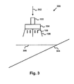
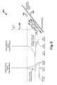
- Fig. 3 is a pictorial diagram 300 of the VTOL UAV 100 vertically descending 302 above an inclined surface 304.
- the landing flight control mode is engaged either manually by the operator or automatically when the UAV's above ground level (AGL) sensor determines that the UAV 100 is at a predetermined height above the inclined surface 304.
- the landing flight control mode is preferably a software program that is executed by the flight control system 110.
- the landing flight control mode monitors the attitude orientation of the UAV 100 from data derived from the navigation system 112. In a normal descent, the UAV 100 is above an attitude 306 where the surface pressure affects the UAV 100 and the pressure differential across the lower duct 104 is uniform.
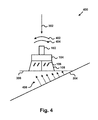
- the UAV 100 detects a pressure differential 406 as seen in Fig. 4 .
- the pressure differential 406 may be inferred from the attitude data without the use of pressure sensors. Alternatively, the pressure differential 406 may be detected with the use of pressure sensors.
- Fig. 4 is a pictorial diagram 400 of the VTOL UAV 100 as it further descends above the inclined surface 304.
- the flight control system 110 is operable to detect and compensate for the pressure differential 406 encountered by the UAV 100.
- the flight control system 110 detects and compensates for the pressure differential 406 by modulating the vanes 106 and controlling the throttle.
- the flight control system 110 counteracts the motion 404 induced by the surface pressure with a counteracting vane motion 402.
- the vane deflection may vary based on surface inclination, while the throttle setting is based on trusting to maintain vehicle descent rate.
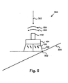
- Fig. 5 is a pictorial diagram 500 of the UAV 100 after the UAV 100 contacts the inclined surface 304 at a contact point 502.
- the landing touch condition is satisfied. This condition may be detected by existing onboard sensors included in the navigation system 112.
- the vanes 106 are adjusted to provide thrust to impart a rotation to the UAV 100 in an uphill direction as illustrated in Fig. 5 .
- the counteracting vane motion 504 is designed to counteract the motion 506 induced by the touch point 502.
- the throttle is also modulated as depicted in Fig. 8 to provide sufficient thrust to counteract gravitational forces on the UAV 100 while the vanes 106 are in transition, but not so much as to detach the landing gear 108 from the incline 304.
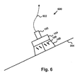
- Fig. 6 is a pictorial diagram 600 of the UAV 100 after the UAV 100 has landed on the inclined surface 304.
- the landing flight control adjusts the vanes 106 to pivot the UAV 100 about the touch point 502 at a controlled rate to gently lower the UAV 100 until all of the landing gear 108 contact the inclined surface 304. At this point, the landing condition is satisfied.
- the landing condition may be detected by existing onboard sensors as a decrease to zero of the vehicle attitude angular rate in spite of continued reductions in throttle.
- a secondary condition for the landing condition is that the onboard sensors detect that the UAV 100 has met the vehicle-specific tip-over angle.
- the throttle is reduced to zero or idle to fully seat the UAV 100.
- the expected throttle settings and vane deflections during the landing flight control mode sequence are shown in Fig. 8 .
- Fig. 7 is a flow chart of a method 700 for vertical takeoff 602 (as shown in Fig. 6 ) from the inclined surface 304.
- the UAV 100 receives a command to launch from an operator.
- a take-off flight control mode is engaged.
- the take-off flight control mode is preferably a software program that is executed by the flight control system 110.
- the take-off flight control mode determines the attitude orientation of the UAV 100 from data sourced by, for example, the navigation system 112.
- the attitude as measured by the navigation system 112 may indicate that the UAV 100 is positioned on the inclined surface 304.
- the take-off flight control mode orients the vanes 106 to a positive angle as depicted in Fig. 6 based on onboard sensor determination of the vehicle attitude relative to the gravity vector.
- the vanes 106 are oriented to counteract gravity relative to the vehicle center-of-gravity 114 such that the UAV 100 is predisposed to release the landing gear 108 from the inclined surface 304 substantially simultaneously.
- the expected throttle settings and vane deflections during the take-off flight control mode sequence are shown in Fig. 9 .
- the UAV 100 starts ascending, initially substantially perpendicular to the take-off surface. Once the UAV 100 is a distance 902 above the inclined surface 304, pre-existing flight controls are engaged to bring the UAV 100 to a full upright attitude for hover or transition to normal flight. For example, the UAV 100 may begin ascending vertically within several duct diameters above the takeoff surface.
- the landing gear may no longer be required to level the UAV 100 on the inclined surface 304.
- the UAV 100 can implement more missions in a wider variety of terrains. Both military and commercial (e.g., police, firefighters, border patrol, forest service, and security) users of the UAV 100 may benefit from the improved versatility of the UAV 100.
Landscapes
- Engineering & Computer Science (AREA)
- Aviation & Aerospace Engineering (AREA)
- Radar, Positioning & Navigation (AREA)
- Remote Sensing (AREA)
- Physics & Mathematics (AREA)
- General Physics & Mathematics (AREA)
- Automation & Control Theory (AREA)
- Chemical & Material Sciences (AREA)
- Combustion & Propulsion (AREA)
- Mechanical Engineering (AREA)
- Control Of Position, Course, Altitude, Or Attitude Of Moving Bodies (AREA)
Abstract
Description
- The United States Government has acquired certain rights in this invention pursuant to Contract No. HR0011-05-C-0043 awarded by DARPA.
- The present invention relates generally to vertical takeoff and landing, and more particularly, relates to vertical takeoff from and landing on inclined surfaces.
- To date, Unmanned Air Vehicles (UAVs) have typically been fixed wing air vehicles; however, other types of UAV are currently being developed for both military and civilian use. One type of UAV currently being developed is a ducted-fan, vertical take-off and landing (VTOL) air vehicle. The VTOL UAV may be capable of operating in a variety of areas, such as constrained urban areas and non-urban areas commonly described as having "complex" terrain.
- The VTOL UAV is designed to perform autonomous missions that generally require the UAV to launch vertically, fly along a pre-planned flight plan, and land vertically. For example, at some point while flying a mission, the UAV may be expected to perform "perch and stare" observations. Perch and stare observations require the UAV to land vertically, perform observations (possibly for an extended period of time with engine shutdown), and takeoff vertically.
- A mission may require the VTOL UAV to takeoff from and land on unprepared ground or vehicle decks. The takeoff and landing surfaces may not be level and, for example, may be inclined up to as much as 30 degrees or more. Traditionally, mechanical landing gear mechanisms have been designed to level the UAV so that the UAV can vertically takeoff from and land on inclined surfaces. Unfortunately, these mechanical landing gear mechanisms are complex and heavy, which may compromise both the durability and flight performance of the UAV. Additionally, some of these mechanical landing gear mechanisms are limited to inclines of 10 degrees or less, which may limit the UAV from performing missions in certain terrain conditions.
- Thus, it would be beneficial for a VTOL UAV to be able to vertically takeoff from and land on an inclined surface without using a mechanical landing gear mechanism to compensate for the incline.
- A method for landing an unmanned air vehicle on an inclined surface is described. The method includes descending vertically above the inclined surface, detecting a pressure differential caused by the inclined surface, counteracting motion caused by the pressure differential, detecting when the unmanned air vehicle contacts the inclined surface, and when the unmanned air vehicle contacts the inclined surface, rotating the unmanned air vehicle until the unmanned vehicle has landed on the inclined surface.
- To counteract motion caused by the pressure differential, vanes of the unmanned air vehicle may be adjusted. Additionally, the throttle of the unmanned air vehicle may be adjusted to counteract the motion caused by the pressure differential. A flight control system of the unmanned air vehicle may detect a landing touch condition.
- To rotate the unmanned air vehicle, the vanes of the unmanned air vehicle may be adjusted. Adjusting the vanes may include moving the vanes to counteract motion induced when the unmanned air vehicle contacts the inclined surface. Additionally, the throttle of the unmanned air vehicle may be adjusted to control the rate of descent of the vehicle. Adjusting the throttle may include increasing the throttle to counteract gravitational forces.
- A method for vertical takeoff of an unmanned air vehicle from an inclined surface is also described. The method includes receiving a command to launch, determining attitude orientation, orienting vanes of the unmanned air vehicle to counteract gravity, increasing thrust to release landing gear of the unmanned air vehicle from the inclined surface, and ascending substantially perpendicular from the inclined surface.
- Determining attitude orientation may identify whether the unmanned air vehicle is located on the inclined surface. Orienting vanes may include adjusting the vanes to a positive angle based on the attitude orientation determination. The method may also include ascending substantially vertically at a distance above the inclined surface.
- A method for vertical takeoff from and landing on inclined surfaces is also described. The method includes providing a takeoff mode in a flight control system of an unmanned air vehicle. The takeoff mode adjusts at least one vane and a thrust of the unmanned air vehicle so as to initially ascend substantially perpendicular to the inclined surface. The method also includes providing a landing mode in the flight control system of the unmanned air vehicle. The landing mode adjusts the at least one vane and the thrust of the unmanned air vehicle upon detecting that the unmanned air vehicle has contacted the inclined surface at a contact point so as to rotate the unmanned air vehicle about the contact point until the unmanned air vehicle has landed.
- The takeoff mode may adjust the vanes based on an attitude orientation determination. The landing mode may rotate the unmanned air vehicle in an uphill direction. Additionally, the landing mode counteracts motion induced by the contact point.
- These as well as other aspects and advantages will become apparent to those of ordinary skill in the art by reading the following detailed description, with reference where appropriate to the accompanying drawings. Further, it is understood that this summary is merely an example and is not intended to limit the scope of the invention as claimed.
- Presently preferred embodiments are described below in conjunction with the appended drawing figures, wherein like reference numerals refer to like elements in the various figures, and wherein:
-
Fig. 1 is a block diagram of a Vertical Take-Off and Landing (VTOL) Unmanned Air Vehicle (UAV), according to an example; -
Fig. 2 is a flow chart of a method for vertical landing on an incline, according to an example; -
Fig. 3 is a pictorial diagram of the VTOL UAV depicted inFig. 1 vertically descending above an incline, according to an example; -
Fig. 4 is another pictorial diagram of the VTOL UAV depicted inFig. 1 vertically descending above the incline, according to an example; -
Fig. 5 is a pictorial diagram of the VTOL UAV depicted inFig. 1 after the vehicle contacts the incline, according to an example; -
Fig. 6 is a pictorial diagram of the VTOL UAV depicted inFig. 1 after the vehicle has landed on the incline, according to an example; -
Fig. 7 is a flow chart of a method for vertical takeoff from the incline, according to an example; -
Fig. 8 is a chart showing throttle and vane deflection versus altitude during landing, according to an example; and -
Fig. 9 is a chart showing throttle and vane deflection versus altitude during take-off, according to an example. -
Fig. 1 is a block diagram of a Vertical Take-Off and Landing (VTOL) Unmanned Air Vehicle (UAV) 100. Typically, the UAV 100 includes afuselage 102, aduct 104,control vanes 106, andlanding gear 108. TheUAV 100's center ofgravity 114 is typically above thecontrol vanes 106. The UAV 100 includes other components as well and is not limited to any particular VTOL UAV design. For example, the UAV 100 may be an Organic Air Vehicle (OAV) or a Miniature Air Vehicle (MAV). - The
fuselage 102 may be a housing that contains other components of the UAV 100. Thefuselage 102 may contain an engine for powering theUAV 100 and storage of fuel, such as gasoline, for the engine. Thefuselage 102 may also contain components for vehicle operation, such as aflight control system 110 and anavigation system 112. - The
flight control system 110 may include a processor, a data storage device, and mode control software to control the UAV 100 in flight. Theflight control system 110 receives inputs from thenavigation system 112 and/or an operator of theUAV 100. Depending on the inputs and the mode type, such as a landing flight control mode and a take-off flight control mode, theflight control system 110 may adjust the vanes and throttle to control the movement of theUAV 110. - The
navigation system 112 may include inertial measurement sensors, a global positioning satellite (GPS) sensor, an above ground level sensor, barometric pressure sensors, magnetometers, rate sensors, and accelerometers. Additionally, thenavigation system 112 may include a processor and a data storage device. A navigation algorithm may be stored in the data storage device. Thenavigation system 112 may receive data from the sensors and the processor may execute the navigation algorithm to provide as an output a navigation solution. The navigation solution may be an estimate of theUAV 100's position, altitude, height above ground, attitudes (e.g., pitch, roll, yaw), attitude rates, velocity, and/or time. - The
duct 104 includes a fan that draws in air through theduct 104 to provide lift. The fan draws air in through the top of theduct 104 and expels it out the bottom to provide thrust. The thrust produced by theduct 104 and fan combination is powerful enough to enable theUAV 100 to hover, as well as fly. Thecontrol vanes 106 may be located under the fan located within theduct 104. Thecontrol vanes 106 provide thrust vectoring for theUAV 100. - The
landing gear 108 is the structure that supports theUAV 100 when not flying and allows theUAV 100 to land on the ground after a flight. Thelanding gear 108 may be a fixed or active mechanical landing gear mechanism. For example, thelanding gear 108 may include three-point posts or a landing ring. As depicted inFig. 1 , thelanding gear 108 has three-point posts; however, the invention is not limited to this type of landing gear. -
Fig. 2 is a flow chart of amethod 200 for vertical landing on an incline. Atblock 202, theUAV 100 begins descending vertically under the control of a pre-existing flight control mode.Fig. 3 is a pictorial diagram 300 of theVTOL UAV 100 vertically descending 302 above aninclined surface 304. - The landing flight control mode is engaged either manually by the operator or automatically when the UAV's above ground level (AGL) sensor determines that the
UAV 100 is at a predetermined height above theinclined surface 304. The landing flight control mode is preferably a software program that is executed by theflight control system 110. The landing flight control mode monitors the attitude orientation of theUAV 100 from data derived from thenavigation system 112. In a normal descent, theUAV 100 is above anattitude 306 where the surface pressure affects theUAV 100 and the pressure differential across thelower duct 104 is uniform. - At
block 204, theUAV 100 detects a pressure differential 406 as seen inFig. 4 . The pressure differential 406 may be inferred from the attitude data without the use of pressure sensors. Alternatively, the pressure differential 406 may be detected with the use of pressure sensors. -
Fig. 4 is a pictorial diagram 400 of theVTOL UAV 100 as it further descends above theinclined surface 304. When descending against theinclined surface 304, thepressure differential 406 across thelower duct 104 is non-uniform. Theflight control system 110 is operable to detect and compensate for the pressure differential 406 encountered by theUAV 100. - At
block 206, theflight control system 110 detects and compensates for the pressure differential 406 by modulating thevanes 106 and controlling the throttle. Theflight control system 110 counteracts the motion 404 induced by the surface pressure with a counteractingvane motion 402. The vane deflection may vary based on surface inclination, while the throttle setting is based on trusting to maintain vehicle descent rate. - At
block 208, theflight control system 110 detects a landing touch condition as shown inFig. 5. Fig. 5 is a pictorial diagram 500 of theUAV 100 after theUAV 100 contacts theinclined surface 304 at acontact point 502. When the contact with theinclined surface 304 induces an orientation change that cannot be corrected by theflight control system 110, the landing touch condition is satisfied. This condition may be detected by existing onboard sensors included in thenavigation system 112. - At
block 210, after the landing touch condition is detected, thevanes 106 are adjusted to provide thrust to impart a rotation to theUAV 100 in an uphill direction as illustrated inFig. 5 . The counteractingvane motion 504 is designed to counteract the motion 506 induced by thetouch point 502. The throttle is also modulated as depicted inFig. 8 to provide sufficient thrust to counteract gravitational forces on theUAV 100 while thevanes 106 are in transition, but not so much as to detach thelanding gear 108 from theincline 304. - At
block 212, theUAV 100 lands on theinclined surface 304 as depicted inFig. 6. Fig. 6 is a pictorial diagram 600 of theUAV 100 after theUAV 100 has landed on theinclined surface 304. The landing flight control adjusts thevanes 106 to pivot theUAV 100 about thetouch point 502 at a controlled rate to gently lower theUAV 100 until all of thelanding gear 108 contact theinclined surface 304. At this point, the landing condition is satisfied. - The landing condition may be detected by existing onboard sensors as a decrease to zero of the vehicle attitude angular rate in spite of continued reductions in throttle. A secondary condition for the landing condition is that the onboard sensors detect that the
UAV 100 has met the vehicle-specific tip-over angle. When the landing condition is met, the throttle is reduced to zero or idle to fully seat theUAV 100. The expected throttle settings and vane deflections during the landing flight control mode sequence are shown inFig. 8 . -
Fig. 7 is a flow chart of amethod 700 for vertical takeoff 602 (as shown inFig. 6 ) from theinclined surface 304. Atblock 702, theUAV 100 receives a command to launch from an operator. Upon receipt of the launch control, a take-off flight control mode is engaged. The take-off flight control mode is preferably a software program that is executed by theflight control system 110. - At
block 704, the take-off flight control mode determines the attitude orientation of theUAV 100 from data sourced by, for example, thenavigation system 112. The attitude as measured by thenavigation system 112 may indicate that theUAV 100 is positioned on theinclined surface 304. - At
block 706, the take-off flight control mode orients thevanes 106 to a positive angle as depicted inFig. 6 based on onboard sensor determination of the vehicle attitude relative to the gravity vector. When the throttle is increased to generate take-off thrust, thevanes 106 are oriented to counteract gravity relative to the vehicle center-of-gravity 114 such that theUAV 100 is predisposed to release thelanding gear 108 from theinclined surface 304 substantially simultaneously. The expected throttle settings and vane deflections during the take-off flight control mode sequence are shown inFig. 9 . - At
block 708, theUAV 100 starts ascending, initially substantially perpendicular to the take-off surface. Once theUAV 100 is adistance 902 above theinclined surface 304, pre-existing flight controls are engaged to bring theUAV 100 to a full upright attitude for hover or transition to normal flight. For example, theUAV 100 may begin ascending vertically within several duct diameters above the takeoff surface. - By adding takeoff and landing modes to the UAV's flight control system, the landing gear may no longer be required to level the
UAV 100 on theinclined surface 304. As a result, theUAV 100 can implement more missions in a wider variety of terrains. Both military and commercial (e.g., police, firefighters, border patrol, forest service, and security) users of theUAV 100 may benefit from the improved versatility of theUAV 100. - It should be understood that the illustrated embodiments are examples only and should not be taken as limiting the scope of the present invention. For example, the invention may be used in other VTOL vehicles. The claims should not be read as limited to the described order or elements unless stated to that effect. Therefore, all embodiments that come within the scope and spirit of the following claims and equivalents thereto are claimed as the invention.
Claims (10)
- A method for landing an unmanned air vehicle on an inclined surface, comprising in combination:descending vertically above the inclined surface;detecting a pressure differential caused by the inclined surface;counteracting motion caused by the pressure differential;detecting when the unmanned air vehicle contacts the inclined surface;when the unmanned air vehicle contacts the inclined surface, rotating the unmanned air vehicle until the unmanned vehicle has landed on the inclined surface.
- The method of claim 1, wherein counteracting motion caused by the pressure differential includes adjusting a throttle of the unmanned air vehicle.
- The method of claim 1, wherein detecting when the unmanned air vehicle contacts the inclined surface includes a flight control system of the unmanned air vehicle detecting a landing touch condition.
- The method of claim 1, wherein rotating the unmanned air vehicle includes adjusting a throttle of the unmanned air vehicle.
- The method of claim 4, wherein adjusting the throttle includes modulating the throttle to counteract gravitational forces.
- A method for vertical takeoff of an unmanned air vehicle from an inclined surface, comprising in combination:receiving a command to launch;determining attitude orientation;orienting vanes of the unmanned air vehicle to counteract gravity;increasing thrust to release landing gear of the unmanned air vehicle from the inclined surface; andascending substantially perpendicular from the inclined surface.
- The method of claim 6, wherein determining attitude orientation identifies whether the unmanned air vehicle is located on the inclined surface.
- The method of claim 6, further comprising ascending substantially vertically at a distance above the inclined surface.
- A method for vertical takeoff from and landing on inclined surfaces, comprising:providing a takeoff mode in a flight control system of an unmanned air vehicle, wherein the takeoff mode adjusts at least one vane and a thrust of the unmanned air vehicle so as to initially ascend substantially perpendicular to the inclined surface; andproviding a landing mode in the flight control system of the unmanned air vehicle, wherein the landing mode adjusts the at least one vane and the thrust of the unmanned air vehicle upon detecting that the unmanned air vehicle has contacted the inclined surface at a contact point so as to rotate the unmanned air vehicle about the contact point until the unmanned air vehicle has landed.
- The method of claim 9, wherein the takeoff mode adjusts the vanes based on an attitude orientation determination.
Applications Claiming Priority (1)
| Application Number | Priority Date | Filing Date | Title |
|---|---|---|---|
| US11/752,497 US7871044B2 (en) | 2007-05-23 | 2007-05-23 | Method for vertical takeoff from and landing on inclined surfaces |
Publications (2)
| Publication Number | Publication Date |
|---|---|
| EP1995174A2 true EP1995174A2 (en) | 2008-11-26 |
| EP1995174A3 EP1995174A3 (en) | 2013-04-24 |
Family
ID=39561797
Family Applications (1)
| Application Number | Title | Priority Date | Filing Date |
|---|---|---|---|
| EP08101858.2A Withdrawn EP1995174A3 (en) | 2007-05-23 | 2008-02-21 | Method for vertical takeoff from and landing on inclined surfaces |
Country Status (3)
| Country | Link |
|---|---|
| US (2) | US7871044B2 (en) |
| EP (1) | EP1995174A3 (en) |
| JP (1) | JP2008290704A (en) |
Cited By (9)
| Publication number | Priority date | Publication date | Assignee | Title |
|---|---|---|---|---|
| EP2236417A1 (en) | 2009-04-02 | 2010-10-06 | Honeywell International Inc. | Method and device for controlling the attitude of an unmanned aerial vehicle using only one axis of three-axis magnetometer |
| EP2386925A1 (en) * | 2010-04-27 | 2011-11-16 | Honeywell International, Inc. | Ground proximity sensor for a UAV |
| CN105388901A (en) * | 2014-08-26 | 2016-03-09 | 鹦鹉股份有限公司 | Method of dynamic control of a rotary- wing drone in throw start |
| CN108873930A (en) * | 2018-05-31 | 2018-11-23 | 苏州市启献智能科技有限公司 | Unmanned plane landing method and system based on mobile platform |
| CN109634296A (en) * | 2018-12-18 | 2019-04-16 | 南京航空航天大学 | Small drone catapult-assisted take-off control system and method based on the robust theory of servomechanism |
| CN110816861A (en) * | 2018-08-08 | 2020-02-21 | 极光飞行科学公司 | Aircraft landing system and method for monitoring vertical landing of aircraft |
| CN114365058A (en) * | 2019-09-17 | 2022-04-15 | 索尼集团公司 | Flight vehicle, control method, and program |
| WO2022113087A1 (en) * | 2020-11-30 | 2022-06-02 | Efix Aviation Ltd | Rotorcraft |
| WO2022226932A1 (en) * | 2021-04-29 | 2022-11-03 | 深圳市大疆创新科技有限公司 | Unmanned aerial vehicle |
Families Citing this family (35)
| Publication number | Priority date | Publication date | Assignee | Title |
|---|---|---|---|---|
| US8200375B2 (en) * | 2008-02-12 | 2012-06-12 | Stuckman Katherine C | Radio controlled aircraft, remote controller and methods for use therewith |
| US8878111B2 (en) | 2009-02-24 | 2014-11-04 | Blue Origin, Llc | Bidirectional control surfaces for use with high speed vehicles, and associated systems and methods |
| US20100302359A1 (en) | 2009-06-01 | 2010-12-02 | Honeywell International Inc. | Unmanned Aerial Vehicle Communication |
| FR2973335B1 (en) * | 2011-03-29 | 2013-04-19 | Inst Superieur De L Aeronautique Et De L Espace | MICRO / NANO REMOTE CONTROL VEHICLE COMPRISING A SYSTEM FOR FLOOR, VERTICAL TAKEOFF AND LANDING |
| US20150286216A1 (en) * | 2012-10-31 | 2015-10-08 | The University Of Tokushima | Conveyance device and control method for flight vehicle |
| KR101447809B1 (en) | 2013-03-22 | 2014-10-08 | 김명호 | Aerial Vehicle With Mltipurpose Grip Type Taking Off an Landing Devic |
| US9547991B2 (en) | 2013-05-23 | 2017-01-17 | Honeywell International Inc. | Aircraft precision approach and shipboard landing control system and method |
| CN103543744B (en) * | 2013-09-10 | 2016-04-27 | 江苏省地质勘查技术院 | A kind of method that unmanned airship airborne magnetic survey line of flight is arranged |
| ES2746980T3 (en) | 2014-01-30 | 2020-03-09 | Boeing Co | Unmanned aerial vehicle |
| CN103869817A (en) * | 2014-03-03 | 2014-06-18 | 东南大学 | Vertical take-off and landing control method for quad-tilt-rotor unmanned aerial vehicle |
| CN106200681B (en) * | 2014-03-27 | 2020-03-06 | 深圳市大疆创新科技有限公司 | Method and system for assisting take-off of movable object |
| US9767701B2 (en) | 2014-06-26 | 2017-09-19 | Amazon Technologies, Inc. | Ground effect based surface sensing in automated aerial vehicles |
| CN104330071B (en) * | 2014-10-14 | 2016-09-14 | 南昌航空大学 | A kind of control the pre-detection method that small-sized depopulated helicopter steadily takes off |
| US9033276B1 (en) * | 2015-01-07 | 2015-05-19 | TLL Associates | Telescoping landing leg system |
| KR101872295B1 (en) * | 2015-04-21 | 2018-06-29 | 순천대학교 산학협력단 | Apparatus for attitude stabilization of small unmanned aerial vehicle |
| TW201643579A (en) * | 2015-06-15 | 2016-12-16 | 鴻海精密工業股份有限公司 | System and method for automatically driving UAV |
| CN105059558B (en) * | 2015-07-16 | 2018-02-02 | 珠海云洲智能科技有限公司 | Unmanned boat-carrying unmanned plane landing system |
| US9448562B1 (en) * | 2015-08-18 | 2016-09-20 | Skycatch, Inc. | Utilizing acceleration information for precision landing of unmanned aerial vehicles |
| US9513635B1 (en) * | 2015-12-30 | 2016-12-06 | Unmanned Innovation, Inc. | Unmanned aerial vehicle inspection system |
| US9740200B2 (en) | 2015-12-30 | 2017-08-22 | Unmanned Innovation, Inc. | Unmanned aerial vehicle inspection system |
| US9618940B1 (en) | 2015-12-31 | 2017-04-11 | Unmanned Innovation, Inc. | Unmanned aerial vehicle rooftop inspection system |
| CN105480413B (en) * | 2016-02-03 | 2019-01-22 | 英华达(上海)科技有限公司 | Unmanned gyroplane and the flying method for controlling unmanned gyroplane |
| US9994307B2 (en) * | 2016-03-25 | 2018-06-12 | The United States Of America As Represented By Secretary Of The Navy | Vertical take-off-and-landing unmanned aerial vehicle system capable of landing on uneven or sloped terrain |
| US11029352B2 (en) | 2016-05-18 | 2021-06-08 | Skydio, Inc. | Unmanned aerial vehicle electromagnetic avoidance and utilization system |
| WO2018057068A2 (en) * | 2016-06-01 | 2018-03-29 | Blue Origin, Llc | Severe weather agility thrusters, and associated systems and methods |
| CN105974931B (en) * | 2016-06-30 | 2019-04-09 | 西安电子科技大学 | A kind of display system for UAV Landing display instrument |
| WO2018027338A1 (en) * | 2016-08-06 | 2018-02-15 | SZ DJI Technology Co., Ltd. | Automatic terrain evaluation of landing surfaces, and associated systems and methods |
| JP6776752B2 (en) * | 2016-09-13 | 2020-10-28 | 富士通株式会社 | Flight equipment, flight equipment control program and flight equipment control method |
| CN106647785B (en) * | 2016-11-16 | 2020-07-14 | 深圳市元征科技股份有限公司 | Unmanned aerial vehicle parking apron control method and device |
| KR101867737B1 (en) * | 2016-12-23 | 2018-06-15 | 주식회사 포스코 | Drone for detecting and protecting corrsion of structure |
| US10822122B2 (en) | 2016-12-28 | 2020-11-03 | Blue Origin, Llc | Vertical landing systems for space vehicles and associated methods |
| US10099802B2 (en) | 2017-02-14 | 2018-10-16 | Honeywell International Inc. | Methods and systems to detect and alert a dynamic rollover condition for an aircraft |
| JP6751935B2 (en) * | 2018-02-28 | 2020-09-09 | 株式会社ナイルワークス | Agricultural drone with improved safety |
| JP7357248B2 (en) * | 2019-02-01 | 2023-10-06 | パナソニックIpマネジメント株式会社 | Unmanned aerial vehicles, information processing methods and programs |
| JP7196668B2 (en) * | 2019-02-14 | 2022-12-27 | 株式会社Ihi | flying object |
Citations (2)
| Publication number | Priority date | Publication date | Assignee | Title |
|---|---|---|---|---|
| EP0752634A1 (en) | 1995-07-07 | 1997-01-08 | Sacom Co., Ltd | Apparatus for controlling the attitude of a radio-controlled helicopter |
| EP1193168A2 (en) | 2000-09-26 | 2002-04-03 | Rafael Armament Development Authority Ltd. | Unmanned mobile device |
Family Cites Families (9)
| Publication number | Priority date | Publication date | Assignee | Title |
|---|---|---|---|---|
| FR1389617A (en) * | 1964-01-09 | 1965-02-19 | Nord Aviation | Unmanned flying machine |
| US3857533A (en) * | 1974-01-28 | 1974-12-31 | S Mason | Helicopter self-leveling landing gear |
| US4062507A (en) * | 1977-02-03 | 1977-12-13 | Felder Donald W | Slope landing compensator system |
| FR2758790B1 (en) * | 1997-01-27 | 1999-05-07 | Sci Chaneac Et Fils | IMPROVEMENT OF A VERTICAL TAKE OFF AIRCRAFT |
| JPH11115896A (en) * | 1997-10-17 | 1999-04-27 | Komatsu Ltd | Unmanned and freely controlled flying body with low speed |
| WO2000015497A2 (en) * | 1998-08-27 | 2000-03-23 | Nicolae Bostan | Gyrostabilized self propelled aircraft |
| US7032861B2 (en) * | 2002-01-07 | 2006-04-25 | Sanders Jr John K | Quiet vertical takeoff and landing aircraft using ducted, magnetic induction air-impeller rotors |
| EP1831073A2 (en) * | 2004-12-22 | 2007-09-12 | Aurora Flight Sciences Corporation | System and method for utilizing stored electrical energy for vtol aircraft thrust enhancement and attitude control |
| US7946528B2 (en) * | 2005-04-15 | 2011-05-24 | Urban Aeronautics, Ltd. | Flight control system especially suited for VTOL vehicles |
-
2007
- 2007-05-23 US US11/752,497 patent/US7871044B2/en not_active Expired - Fee Related
-
2008
- 2008-02-21 EP EP08101858.2A patent/EP1995174A3/en not_active Withdrawn
- 2008-02-22 JP JP2008042051A patent/JP2008290704A/en active Pending
-
2010
- 2010-11-18 US US12/949,410 patent/US8141823B2/en not_active Expired - Fee Related
Patent Citations (2)
| Publication number | Priority date | Publication date | Assignee | Title |
|---|---|---|---|---|
| EP0752634A1 (en) | 1995-07-07 | 1997-01-08 | Sacom Co., Ltd | Apparatus for controlling the attitude of a radio-controlled helicopter |
| EP1193168A2 (en) | 2000-09-26 | 2002-04-03 | Rafael Armament Development Authority Ltd. | Unmanned mobile device |
Cited By (13)
| Publication number | Priority date | Publication date | Assignee | Title |
|---|---|---|---|---|
| US8386095B2 (en) | 2009-04-02 | 2013-02-26 | Honeywell International Inc. | Performing corrective action on unmanned aerial vehicle using one axis of three-axis magnetometer |
| EP2236417A1 (en) | 2009-04-02 | 2010-10-06 | Honeywell International Inc. | Method and device for controlling the attitude of an unmanned aerial vehicle using only one axis of three-axis magnetometer |
| EP2386925A1 (en) * | 2010-04-27 | 2011-11-16 | Honeywell International, Inc. | Ground proximity sensor for a UAV |
| US8135503B2 (en) | 2010-04-27 | 2012-03-13 | Honeywell International Inc. | Ground proximity sensor |
| CN105388901A (en) * | 2014-08-26 | 2016-03-09 | 鹦鹉股份有限公司 | Method of dynamic control of a rotary- wing drone in throw start |
| CN108873930A (en) * | 2018-05-31 | 2018-11-23 | 苏州市启献智能科技有限公司 | Unmanned plane landing method and system based on mobile platform |
| CN108873930B (en) * | 2018-05-31 | 2021-09-10 | 苏州市启献智能科技有限公司 | Unmanned aerial vehicle taking-off and landing method and system based on mobile platform |
| CN110816861B (en) * | 2018-08-08 | 2023-10-03 | 极光飞行科学公司 | Aircraft landing system and method for monitoring vertical landing of aircraft |
| CN110816861A (en) * | 2018-08-08 | 2020-02-21 | 极光飞行科学公司 | Aircraft landing system and method for monitoring vertical landing of aircraft |
| CN109634296A (en) * | 2018-12-18 | 2019-04-16 | 南京航空航天大学 | Small drone catapult-assisted take-off control system and method based on the robust theory of servomechanism |
| CN114365058A (en) * | 2019-09-17 | 2022-04-15 | 索尼集团公司 | Flight vehicle, control method, and program |
| WO2022113087A1 (en) * | 2020-11-30 | 2022-06-02 | Efix Aviation Ltd | Rotorcraft |
| WO2022226932A1 (en) * | 2021-04-29 | 2022-11-03 | 深圳市大疆创新科技有限公司 | Unmanned aerial vehicle |
Also Published As
| Publication number | Publication date |
|---|---|
| US7871044B2 (en) | 2011-01-18 |
| JP2008290704A (en) | 2008-12-04 |
| US20110057075A1 (en) | 2011-03-10 |
| US8141823B2 (en) | 2012-03-27 |
| EP1995174A3 (en) | 2013-04-24 |
| US20100012776A1 (en) | 2010-01-21 |
Similar Documents
| Publication | Publication Date | Title |
|---|---|---|
| US7871044B2 (en) | Method for vertical takeoff from and landing on inclined surfaces | |
| US10474167B2 (en) | System, a method and a computer program product for maneuvering of an air vehicle with tiltable propulsion unit | |
| US9540100B2 (en) | System, a method and a computer program product for maneuvering of an air vehicle | |
| NL2017971B1 (en) | Unmanned aerial vehicle | |
| US8386095B2 (en) | Performing corrective action on unmanned aerial vehicle using one axis of three-axis magnetometer | |
| NL2018003B1 (en) | Unmanned aerial vehicle | |
| US11858626B2 (en) | Autonomous air vehicle delivery system incorporating deployment | |
| JP2010168034A (en) | Alternative method of ducted fan uav control system | |
| CN106043695B (en) | A kind of dynamic multi-rotor unmanned aerial vehicle fixed pitch variable speed system of oil and control technology | |
| US11479353B2 (en) | Distributed elevon systems for tailsitting biplane aircraft | |
| CN115016514B (en) | Full-autonomous flight control method for takeoff, cruising and landing of bionic ornithopter | |
| JP7466217B2 (en) | Take-off and Landing System | |
| US20220291697A1 (en) | Yaw Control Systems for Tailsitting Biplane Aircraft | |
| AU2020364319B2 (en) | Contingent use of commanded speed in lieu of sensed airspeed to inform flight control decisions | |
| CN204021249U (en) | The soft wing unmanned plane of high-mobility, multipurpose, wheeled vehicle | |
| JP2008201183A (en) | Attitude controlling device | |
| US11479354B2 (en) | Thrust vectoring coaxial rotor systems for aircraft | |
| NL1040979B1 (en) | Air vehicle. | |
| Pelletier et al. | Autonomous navigation and control functions of the CL-327 VTOL UAV | |
| EP4408744A1 (en) | Closed polygonal wing member and uses thereof | |
| Smouter | Autonomous Vertical Recovery of Fixed Wing Unmanned Aerial Vehicles | |
| Singh | Development of Ground Station and Onboard Sensors for an Autonomous Mini Helicopter |
Legal Events
| Date | Code | Title | Description |
|---|---|---|---|
| PUAI | Public reference made under article 153(3) epc to a published international application that has entered the european phase |
Free format text: ORIGINAL CODE: 0009012 |
|
| 17P | Request for examination filed |
Effective date: 20080221 |
|
| AK | Designated contracting states |
Kind code of ref document: A2 Designated state(s): AT BE BG CH CY CZ DE DK EE ES FI FR GB GR HR HU IE IS IT LI LT LU LV MC MT NL NO PL PT RO SE SI SK TR |
|
| AX | Request for extension of the european patent |
Extension state: AL BA MK RS |
|
| PUAL | Search report despatched |
Free format text: ORIGINAL CODE: 0009013 |
|
| AK | Designated contracting states |
Kind code of ref document: A3 Designated state(s): AT BE BG CH CY CZ DE DK EE ES FI FR GB GR HR HU IE IS IT LI LT LU LV MC MT NL NO PL PT RO SE SI SK TR |
|
| AX | Request for extension of the european patent |
Extension state: AL BA MK RS |
|
| RIC1 | Information provided on ipc code assigned before grant |
Ipc: B64D 45/04 20060101ALI20130321BHEP Ipc: G05D 1/08 20060101ALI20130321BHEP Ipc: B64C 27/20 20060101AFI20130321BHEP Ipc: B64C 39/02 20060101ALI20130321BHEP |
|
| 17Q | First examination report despatched |
Effective date: 20130411 |
|
| AKX | Designation fees paid |
Designated state(s): DE FR GB |
|
| GRAP | Despatch of communication of intention to grant a patent |
Free format text: ORIGINAL CODE: EPIDOSNIGR1 |
|
| INTG | Intention to grant announced |
Effective date: 20141023 |
|
| STAA | Information on the status of an ep patent application or granted ep patent |
Free format text: STATUS: THE APPLICATION IS DEEMED TO BE WITHDRAWN |
|
| 18D | Application deemed to be withdrawn |
Effective date: 20150303 |