JP2008286133A - Scuffing prevention method and device for marine internal combustion engine - Google Patents
Scuffing prevention method and device for marine internal combustion engine Download PDFInfo
- Publication number
- JP2008286133A JP2008286133A JP2007133095A JP2007133095A JP2008286133A JP 2008286133 A JP2008286133 A JP 2008286133A JP 2007133095 A JP2007133095 A JP 2007133095A JP 2007133095 A JP2007133095 A JP 2007133095A JP 2008286133 A JP2008286133 A JP 2008286133A
- Authority
- JP
- Japan
- Prior art keywords
- fuel
- engine
- engine speed
- scuffing
- cylinder
- Prior art date
- Legal status (The legal status is an assumption and is not a legal conclusion. Google has not performed a legal analysis and makes no representation as to the accuracy of the status listed.)
- Granted
Links
Images


Classifications
-
- F—MECHANICAL ENGINEERING; LIGHTING; HEATING; WEAPONS; BLASTING
- F02—COMBUSTION ENGINES; HOT-GAS OR COMBUSTION-PRODUCT ENGINE PLANTS
- F02M—SUPPLYING COMBUSTION ENGINES IN GENERAL WITH COMBUSTIBLE MIXTURES OR CONSTITUENTS THEREOF
- F02M37/00—Apparatus or systems for feeding liquid fuel from storage containers to carburettors or fuel-injection apparatus; Arrangements for purifying liquid fuel specially adapted for, or arranged on, internal-combustion engines
- F02M37/0076—Details of the fuel feeding system related to the fuel tank
- F02M37/0088—Multiple separate fuel tanks or tanks being at least partially partitioned
-
- F—MECHANICAL ENGINEERING; LIGHTING; HEATING; WEAPONS; BLASTING
- F02—COMBUSTION ENGINES; HOT-GAS OR COMBUSTION-PRODUCT ENGINE PLANTS
- F02M—SUPPLYING COMBUSTION ENGINES IN GENERAL WITH COMBUSTIBLE MIXTURES OR CONSTITUENTS THEREOF
- F02M25/00—Engine-pertinent apparatus for adding non-fuel substances or small quantities of secondary fuel to combustion-air, main fuel or fuel-air mixture
-
- B—PERFORMING OPERATIONS; TRANSPORTING
- B63—SHIPS OR OTHER WATERBORNE VESSELS; RELATED EQUIPMENT
- B63H—MARINE PROPULSION OR STEERING
- B63H21/00—Use of propulsion power plant or units on vessels
- B63H21/12—Use of propulsion power plant or units on vessels the vessels being motor-driven
- B63H21/14—Use of propulsion power plant or units on vessels the vessels being motor-driven relating to internal-combustion engines
-
- F—MECHANICAL ENGINEERING; LIGHTING; HEATING; WEAPONS; BLASTING
- F01—MACHINES OR ENGINES IN GENERAL; ENGINE PLANTS IN GENERAL; STEAM ENGINES
- F01M—LUBRICATING OF MACHINES OR ENGINES IN GENERAL; LUBRICATING INTERNAL COMBUSTION ENGINES; CRANKCASE VENTILATING
- F01M1/00—Pressure lubrication
- F01M1/08—Lubricating systems characterised by the provision therein of lubricant jetting means
-
- F—MECHANICAL ENGINEERING; LIGHTING; HEATING; WEAPONS; BLASTING
- F01—MACHINES OR ENGINES IN GENERAL; ENGINE PLANTS IN GENERAL; STEAM ENGINES
- F01M—LUBRICATING OF MACHINES OR ENGINES IN GENERAL; LUBRICATING INTERNAL COMBUSTION ENGINES; CRANKCASE VENTILATING
- F01M1/00—Pressure lubrication
- F01M1/16—Controlling lubricant pressure or quantity
-
- F—MECHANICAL ENGINEERING; LIGHTING; HEATING; WEAPONS; BLASTING
- F01—MACHINES OR ENGINES IN GENERAL; ENGINE PLANTS IN GENERAL; STEAM ENGINES
- F01M—LUBRICATING OF MACHINES OR ENGINES IN GENERAL; LUBRICATING INTERNAL COMBUSTION ENGINES; CRANKCASE VENTILATING
- F01M3/00—Lubrication specially adapted for engines with crankcase compression of fuel-air mixture or for other engines in which lubricant is contained in fuel, combustion air, or fuel-air mixture
- F01M3/02—Lubrication specially adapted for engines with crankcase compression of fuel-air mixture or for other engines in which lubricant is contained in fuel, combustion air, or fuel-air mixture with variable proportion of lubricant to fuel, lubricant to air, or lubricant to fuel-air-mixture
-
- F—MECHANICAL ENGINEERING; LIGHTING; HEATING; WEAPONS; BLASTING
- F01—MACHINES OR ENGINES IN GENERAL; ENGINE PLANTS IN GENERAL; STEAM ENGINES
- F01M—LUBRICATING OF MACHINES OR ENGINES IN GENERAL; LUBRICATING INTERNAL COMBUSTION ENGINES; CRANKCASE VENTILATING
- F01M3/00—Lubrication specially adapted for engines with crankcase compression of fuel-air mixture or for other engines in which lubricant is contained in fuel, combustion air, or fuel-air mixture
- F01M3/04—Lubrication specially adapted for engines with crankcase compression of fuel-air mixture or for other engines in which lubricant is contained in fuel, combustion air, or fuel-air mixture for upper cylinder lubrication only
-
- F—MECHANICAL ENGINEERING; LIGHTING; HEATING; WEAPONS; BLASTING
- F02—COMBUSTION ENGINES; HOT-GAS OR COMBUSTION-PRODUCT ENGINE PLANTS
- F02D—CONTROLLING COMBUSTION ENGINES
- F02D19/00—Controlling engines characterised by their use of non-liquid fuels, pluralities of fuels, or non-fuel substances added to the combustible mixtures
- F02D19/12—Controlling engines characterised by their use of non-liquid fuels, pluralities of fuels, or non-fuel substances added to the combustible mixtures peculiar to engines working with non-fuel substances or with anti-knock agents, e.g. with anti-knock fuel
-
- F—MECHANICAL ENGINEERING; LIGHTING; HEATING; WEAPONS; BLASTING
- F02—COMBUSTION ENGINES; HOT-GAS OR COMBUSTION-PRODUCT ENGINE PLANTS
- F02M—SUPPLYING COMBUSTION ENGINES IN GENERAL WITH COMBUSTIBLE MIXTURES OR CONSTITUENTS THEREOF
- F02M37/00—Apparatus or systems for feeding liquid fuel from storage containers to carburettors or fuel-injection apparatus; Arrangements for purifying liquid fuel specially adapted for, or arranged on, internal-combustion engines
-
- Y—GENERAL TAGGING OF NEW TECHNOLOGICAL DEVELOPMENTS; GENERAL TAGGING OF CROSS-SECTIONAL TECHNOLOGIES SPANNING OVER SEVERAL SECTIONS OF THE IPC; TECHNICAL SUBJECTS COVERED BY FORMER USPC CROSS-REFERENCE ART COLLECTIONS [XRACs] AND DIGESTS
- Y02—TECHNOLOGIES OR APPLICATIONS FOR MITIGATION OR ADAPTATION AGAINST CLIMATE CHANGE
- Y02T—CLIMATE CHANGE MITIGATION TECHNOLOGIES RELATED TO TRANSPORTATION
- Y02T10/00—Road transport of goods or passengers
- Y02T10/10—Internal combustion engine [ICE] based vehicles
- Y02T10/12—Improving ICE efficiencies
Landscapes
- Engineering & Computer Science (AREA)
- Mechanical Engineering (AREA)
- General Engineering & Computer Science (AREA)
- Chemical & Material Sciences (AREA)
- Combustion & Propulsion (AREA)
- Ocean & Marine Engineering (AREA)
- Lubrication Of Internal Combustion Engines (AREA)
- Cylinder Crankcases Of Internal Combustion Engines (AREA)
- Output Control And Ontrol Of Special Type Engine (AREA)
- Electrical Control Of Air Or Fuel Supplied To Internal-Combustion Engine (AREA)
Abstract
Description
本発明は、舶用内燃機関のスカッフィング防止方法及び装置に関するものである。 The present invention relates to a scuffing prevention method and apparatus for a marine internal combustion engine.
一般に、舶用内燃機関においては、燃料タンク内に貯留された燃料を燃料ポンプにより圧送し、燃料噴射弁を介してエンジンの各気筒内に供給するようになっている。 Generally, in a marine internal combustion engine, fuel stored in a fuel tank is pumped by a fuel pump and supplied into each cylinder of the engine via a fuel injection valve.
尚、舶用内燃機関の燃料供給に関する一般的技術水準を示すものとしては、例えば、特許文献1がある。
ところで、入出港時や運河通過時等の機関回転数変動時には、シリンダライナに対するピストンリングの摺動状態が厳しくなり、該シリンダライナの摺動面に引っかき傷が付くことにより、その後の運転でいわゆるスカッフィングが発生しやすくなるが、従来の場合、前記機関回転数変動時に特別な配慮はなされていなかった。 By the way, when the engine speed fluctuates such as when entering or leaving a port or passing through a canal, the sliding state of the piston ring relative to the cylinder liner becomes severe, and the sliding surface of the cylinder liner is scratched, so that it is called in the subsequent operation. Scuffing is likely to occur, but in the conventional case, no special consideration has been given when the engine speed fluctuates.
又、燃料中には、該燃料の改質用触媒として利用されたアルミナやシリカ等のセラミックス系の硬質粒子が含まれているため、燃料タンク内に貯留された燃料が減少した際に、該燃料を燃料タンクの底部から抜き出すと、該燃料タンクの底部に沈殿した高濃度の硬質粒子も燃料と一緒に抜き出される形となり、該硬質粒子は燃料清浄機やフィルタでは除去しきれず、エンジンに大量に入り込み、特に、前記機関回転数変動時に硬質粒子がエンジンに大量に入り込んだ場合、シリンダライナに対するピストンリングの摺動状態が更に厳しくなり、スカッフィング発生の起点が形成され、その後の高負荷運転時にスカッフィングが発生するという欠点を有していた。 Further, since the fuel contains ceramic hard particles such as alumina and silica that are used as a catalyst for reforming the fuel, when the fuel stored in the fuel tank decreases, the fuel When fuel is extracted from the bottom of the fuel tank, high-concentration hard particles that have settled at the bottom of the fuel tank are also extracted together with the fuel, and the hard particles cannot be completely removed by a fuel purifier or a filter. When a large amount of hard particles enter the engine, especially when the engine speed fluctuates, the sliding state of the piston ring relative to the cylinder liner becomes more severe, and the starting point of scuffing is formed. It sometimes had the disadvantage of scuffing.
本発明は、斯かる実情に鑑み、機関回転数変動時にシリンダライナに対するピストンリングの摺動状態が厳しくなることを緩和し得、スカッフィングの発生を防止し得る舶用内燃機関のスカッフィング防止方法及び装置を提供しようとするものである。 In view of such circumstances, the present invention provides a scuffing prevention method and apparatus for a marine internal combustion engine that can alleviate the fact that the sliding state of the piston ring with respect to the cylinder liner becomes severe when the engine speed fluctuates and can prevent the occurrence of scuffing. It is something to be offered.
本発明は、燃料タンク内に貯留された燃料を底部から抜き出して燃料ポンプにより圧送し、燃料噴射弁を介してエンジンの各気筒内に供給する舶用内燃機関のスカッフィング防止方法であって、
機関回転数を検出してモニタし、少なくとも機関回転数変動時には、硬質粒子濃度の低い燃料をエンジンの各気筒内に供給する一方、スカッフィング防止剤をエンジンの各気筒内に供給することを特徴とする舶用内燃機関のスカッフィング防止方法にかかるものである。
The present invention is a marine internal combustion engine scuffing prevention method for extracting fuel stored in a fuel tank from the bottom, pumping it by a fuel pump, and supplying the fuel into each cylinder of the engine via a fuel injection valve.
The engine speed is detected and monitored, and at least when the engine speed fluctuates, fuel with a low hard particle concentration is supplied into each cylinder of the engine, while a scuffing inhibitor is supplied into each cylinder of the engine. The present invention relates to a scuffing prevention method for a marine internal combustion engine.
前述の如く構成すると、機関回転数が検出されてモニタされ、少なくとも機関回転数変動時には、硬質粒子濃度の低い燃料がエンジンの各気筒内に供給される一方、スカッフィング防止剤がエンジンの各気筒内に供給される。 When configured as described above, the engine speed is detected and monitored, and at least when the engine speed fluctuates, fuel with a low hard particle concentration is supplied into each cylinder of the engine, while a scuffing inhibitor is contained in each cylinder of the engine. To be supplied.
この結果、機関回転数変動時に硬質粒子がエンジンに大量に入り込むことがなくなる一方、スカッフィング防止剤がエンジンの各気筒内に供給されることから、シリンダライナに対するピストンリングの摺動状態が厳しくならず、スカッフィング発生の起点が形成されにくくなって、その後の高負荷運転時にもスカッフィングが発生しなくなる。 As a result, a large amount of hard particles do not enter the engine when the engine speed fluctuates. On the other hand, since the anti-scuffing agent is supplied into each cylinder of the engine, the sliding state of the piston ring with respect to the cylinder liner does not become severe. The starting point of scuffing is less likely to be formed, and scuffing does not occur during subsequent high load operation.
前記舶用内燃機関のスカッフィング防止方法においては、複数の燃料タンクを備え、所望の燃料タンクから燃料の抜き出しを可能とし、燃料レベルが設定値以下に減少した燃料タンクが存在している場合、平水での機関回転数安定時にのみ、前記燃料レベルが設定値以下に減少した燃料タンクから燃料をエンジンの各気筒内に供給し、機関回転数変動時には、燃料レベルが設定値以下に減少していない燃料タンクから燃料をエンジンの各気筒内に供給するようにすることができる。 The marine internal combustion engine scuffing prevention method includes a plurality of fuel tanks, enables extraction of fuel from a desired fuel tank, and when there is a fuel tank whose fuel level is reduced below a set value, Only when the engine speed is stable, the fuel is supplied into the cylinders of the engine from the fuel tank whose fuel level has decreased below the set value. When the engine speed fluctuates, the fuel level has not decreased below the set value. Fuel can be supplied from the tank into each cylinder of the engine.
前記舶用内燃機関のスカッフィング防止方法においては、前記スカッフィング防止剤をエンジンの各気筒内に注入される潤滑油とし、機関回転数変動時には、潤滑油注入率を上昇させるようにすることもできる。 In the marbling internal combustion engine scuffing prevention method, the scuffing prevention agent may be lubricating oil injected into each cylinder of the engine, and the lubricating oil injection rate may be increased when the engine speed fluctuates.
前記舶用内燃機関のスカッフィング防止方法においては、前記スカッフィング防止剤を燃料に混入される研磨剤とし、機関回転数変動時又は機関回転数変動終了後に、研磨剤が混入された燃料をエンジンの各気筒内に供給するようにしても良い。 In the marine internal combustion engine scuffing prevention method, the anti-scuffing agent is an abrasive mixed in the fuel, and the fuel mixed with the abrasive is used for each cylinder of the engine when the engine speed changes or after the engine speed change ends. You may make it supply in.
一方、本発明は、燃料タンク内に貯留された燃料を底部から抜き出して燃料ポンプにより圧送し、燃料噴射弁を介してエンジンの各気筒内に供給する舶用内燃機関のスカッフィング防止装置であって、
機関回転数を検出する回転検出器と、該回転検出器で検出された機関回転数をモニタする機関回転数モニタ装置とを備え、少なくとも機関回転数変動時には、硬質粒子濃度の低い燃料をエンジンの各気筒内に供給する一方、スカッフィング防止剤をエンジンの各気筒内に供給するよう構成したことを特徴とする舶用内燃機関のスカッフィング防止装置にかかるものである。
On the other hand, the present invention is a scuffing prevention device for a marine internal combustion engine that extracts fuel stored in a fuel tank from the bottom, pumps it with a fuel pump, and supplies the fuel into each cylinder of the engine via a fuel injection valve,
A rotation detector that detects the engine speed and an engine speed monitor device that monitors the engine speed detected by the rotation detector. At least when the engine speed fluctuates, fuel with a low hard particle concentration is supplied to the engine. The present invention relates to a scuffing prevention device for a marine internal combustion engine, characterized in that the scuffing prevention agent is supplied into each cylinder of the engine while being supplied into each cylinder.
該舶用内燃機関のスカッフィング防止装置の場合、回転検出器により機関回転数が検出され、該回転検出器で検出された機関回転数が機関回転数モニタ装置によってモニタされ、少なくとも機関回転数変動時には、硬質粒子濃度の低い燃料がエンジンの各気筒内に供給される一方、スカッフィング防止剤がエンジンの各気筒内に供給される。 In the case of the scuffing prevention device for the marine internal combustion engine, the engine speed is detected by the rotation detector, the engine speed detected by the rotation detector is monitored by the engine speed monitor device, and at least when the engine speed fluctuates, A fuel with a low hard particle concentration is supplied into each cylinder of the engine, while an anti-scuffing agent is supplied into each cylinder of the engine.
この結果、機関回転数変動時に硬質粒子がエンジンに大量に入り込むことがなくなる一方、スカッフィング防止剤がエンジンの各気筒内に供給されることから、シリンダライナに対するピストンリングの摺動状態が厳しくならず、スカッフィング発生の起点が形成されにくくなって、その後の高負荷運転時にもスカッフィングが発生しなくなる。 As a result, a large amount of hard particles do not enter the engine when the engine speed fluctuates. On the other hand, since the anti-scuffing agent is supplied into each cylinder of the engine, the sliding state of the piston ring with respect to the cylinder liner does not become severe. The starting point of scuffing is less likely to be formed, and scuffing does not occur during subsequent high load operation.
前記舶用内燃機関のスカッフィング防止装置においては、複数の燃料タンクと、
所望の燃料タンクから燃料を抜き出し可能となるよう抜出弁が配設された抜出ラインと、
前記各燃料タンクの燃料レベルを検出するレベル検出器と、
該レベル検出器からの検出信号に基づき燃料レベルが設定値以下に減少した燃料タンクが存在している場合、前記機関回転数モニタ装置でモニタされた機関回転数モニタ信号に基づく平水での機関回転数安定時にのみ、前記燃料レベルが設定値以下に減少した燃料タンクから燃料をエンジンの各気筒内に供給することが可能であることを表示する燃料タンク切換可能表示器と
を備え、
前記機関回転数モニタ装置でモニタされた機関回転数モニタ信号に基づく機関回転数変動時には、燃料レベルが設定値以下に減少していない燃料タンクから燃料をエンジンの各気筒内に供給するよう構成することができる。
In the anti-scuffing device for a marine internal combustion engine, a plurality of fuel tanks,
An extraction line provided with an extraction valve so that fuel can be extracted from a desired fuel tank;
A level detector for detecting the fuel level of each fuel tank;
When there is a fuel tank whose fuel level has decreased below a set value based on the detection signal from the level detector, the engine speed in the plain water based on the engine speed monitor signal monitored by the engine speed monitor device A fuel tank switchable indicator for indicating that fuel can be supplied into each cylinder of the engine from a fuel tank whose fuel level has decreased below a set value only at a few stable times, and
When the engine speed varies based on the engine speed monitor signal monitored by the engine speed monitor device, the fuel is supplied from the fuel tank whose fuel level has not decreased below the set value into each cylinder of the engine. be able to.
前記舶用内燃機関のスカッフィング防止装置においては、前記スカッフィング防止剤としての潤滑油が貯留された潤滑油タンクと、
該潤滑油タンクに貯留された潤滑油をエンジンの各気筒内に注入可能となるよう潤滑油投入機構及び潤滑油投入量調節機構が配設された潤滑油注入ラインと、
前記機関回転数モニタ装置でモニタされた機関回転数モニタ信号に基づく機関回転数変動時には、前記潤滑油注入ラインの潤滑油投入量調節機構へ潤滑油注入率を上昇させる開度指令信号を出力する潤滑油注入率制御装置と
を備えるようにすることもできる。
In the anti-scuffing device for a marine internal combustion engine, a lubricating oil tank storing lubricating oil as the anti-scuffing agent,
A lubricating oil injection line in which a lubricating oil charging mechanism and a lubricating oil charging amount adjusting mechanism are arranged so that the lubricating oil stored in the lubricating oil tank can be injected into each cylinder of the engine;
When the engine speed changes based on the engine speed monitor signal monitored by the engine speed monitor device, an opening degree command signal for increasing the lubricating oil injection rate is output to the lubricating oil injection amount adjusting mechanism of the lubricating oil injection line. And a lubricating oil injection rate control device.
前記舶用内燃機関のスカッフィング防止装置においては、前記スカッフィング防止剤としての研磨剤が貯留された研磨剤タンクと、
該研磨剤タンクに貯留された研磨剤を燃料に混入可能となるよう研磨剤ポンプ及び研磨剤混入弁が配設された研磨剤混入ラインと、
前記機関回転数モニタ装置でモニタされた機関回転数モニタ信号に基づく機関回転数変動時又は機関回転数変動終了後に、前記研磨剤混入ラインの研磨剤混入弁へ混入指令信号を出力する研磨剤混入制御装置と
を備えるようにしても良い。
In the anti-scuffing device for a marine internal combustion engine, an abrasive tank storing an abrasive as the anti-scuffing agent,
A polishing agent mixing line in which a polishing agent pump and a polishing agent mixing valve are arranged so that the polishing agent stored in the polishing agent tank can be mixed into the fuel;
Abrasive mixing that outputs a mixing command signal to the polishing agent mixing valve of the polishing agent mixing line at the time of engine speed fluctuation or after completion of the engine speed fluctuation based on the engine speed monitoring signal monitored by the engine speed monitoring device And a control device.
本発明の舶用内燃機関のスカッフィング防止方法及び装置によれば、機関回転数変動時にシリンダライナに対するピストンリングの摺動状態が厳しくなることを緩和し得、スカッフィングの発生を防止し得るという優れた効果を奏し得る。 According to the marine internal combustion engine scuffing prevention method and apparatus of the present invention, it is possible to alleviate the fact that the sliding state of the piston ring with respect to the cylinder liner becomes severe when the engine speed fluctuates, and it is possible to prevent the occurrence of scuffing. Can be played.
以下、本発明の実施の形態を添付図面を参照して説明する。 Embodiments of the present invention will be described below with reference to the accompanying drawings.
図1は本発明を実施する形態の第一例であって、燃料タンク1内に貯留された燃料を底部から抜出ライン2に抜き出して燃料ポンプ3により圧送し、セットリングタンク4と供給ポンプ5と燃料噴射弁6とを介してエンジン7の各気筒8内に供給するようにした舶用内燃機関において、前記燃料タンク1を燃料が満たされた状態で複数(図1の例では三個)設置し、所望の燃料タンク1から燃料を抜き出し可能となるよう前記抜出ライン2に抜出弁9を配設すると共に、前記各燃料タンク1に、燃料レベルを検出するレベル検出器10を設け、前記エンジン7に、機関回転数を検出する回転検出器11と、該回転検出器11で検出された機関回転数の検出信号11aをモニタする機関回転数モニタ装置12とを設け、更に、前記レベル検出器10からの検出信号10aに基づき燃料レベルが設定値以下に減少した燃料タンク1が存在している場合、前記機関回転数モニタ装置12でモニタされた機関回転数モニタ信号12aに基づく平水(水面が波立っていない状態)での機関回転数安定時にのみ、前記燃料レベルが設定値以下に減少した燃料タンク1から燃料をエンジン7の各気筒8内に供給することが可能であることを表示する燃料タンク切換可能表示器13を設け、前記機関回転数モニタ装置12でモニタされた機関回転数モニタ信号12aに基づく機関回転数変動時には、燃料レベルが設定値以下に減少していない燃料タンク1から燃料をエンジン7の各気筒8内に供給するよう構成したものである。
FIG. 1 shows a first example of an embodiment of the present invention, in which fuel stored in a
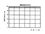
尚、前記機関回転数安定時とは、例えば、図2に示す如く、前記機関回転数の単位時間(一時間)当たりの変動が3%未満となる状態を指し、又、機関回転数変動時とは、例えば、図3に示す如く、前記機関回転数の単位時間(一時間)当たりの変動が15%以上となる状態を指す。 The engine speed is stable when, for example, the engine speed varies less than 3% per unit time (one hour) as shown in FIG. 2, and when the engine speed varies. For example, as shown in FIG. 3, a state in which the fluctuation of the engine speed per unit time (one hour) is 15% or more.
又、船舶の航行中は燃料の補充が行えないため、前記複数の燃料タンク1のトータル容量は、一回の航行距離を充分にカバーできる容量とし、最後に燃料が抜き出される燃料タンク1の燃料レベルが設定値以下に減少する前に少なくとも燃料を補充するものとしてある。
Further, since the fuel cannot be replenished during the navigation of the ship, the total capacity of the plurality of
次に、上記図示例の作用を説明する。 Next, the operation of the illustrated example will be described.
本図示例の場合、燃料が満たされた複数の燃料タンク1のうち、所望の燃料タンク1の抜出弁9を開くことにより、該燃料タンク1の底部から抜出ライン2を経て燃料が抜き出され、燃料ポンプ3によりセットリングタンク4へ圧送され、該セットリングタンク4内に一旦貯留された燃料が供給ポンプ5により燃料噴射弁6へ圧送され、該燃料噴射弁6からエンジン7の各気筒8内に噴射される。
In the case of the illustrated example, the fuel is extracted from the bottom of the
このとき、前記エンジン7の回転数は、回転検出器11によって検出され、その検出信号11aが機関回転数モニタ装置12に入力され、該機関回転数モニタ装置12において前記回転検出器11で検出された機関回転数の検出信号11aがモニタされ、現在の状態が機関回転数安定時であるか、或いは機関回転数変動時であるかを乗員が把握できるようになっていると共に、前記機関回転数モニタ装置12でモニタされた機関回転数モニタ信号12aが燃料タンク切換可能表示器13へ入力されている。
At this time, the rotation speed of the
又、前記燃料タンク1の燃料レベルがレベル検出器10によって検出され、該レベル検出器10によって検出された燃料レベルの検出信号10aが燃料タンク切換可能表示器13へ入力され、該燃料タンク切換可能表示器13において、前記レベル検出器10からの検出信号10aに基づき燃料レベルが設定値以下に減少した燃料タンク1が存在しているか否かの判断が行われ、図1の仮想線で示す如く燃料レベルが設定値以下に減少した燃料タンク1が存在している場合、前記機関回転数モニタ装置12でモニタされた機関回転数モニタ信号12aに基づく平水での機関回転数安定時にのみ、前記燃料レベルが設定値以下に減少した燃料タンク1から燃料をエンジン7の各気筒8内に供給可能であることが表示される。
Further, the fuel level of the
この時点で、燃料レベルが設定値以下に減少していない燃料タンク1から燃料の抜き出しが行われている場合、乗員は、前記燃料タンク切換可能表示器13に、燃料レベルが設定値以下に減少した燃料タンク1から燃料をエンジン7の各気筒8内に供給可能であることが表示されている場合にのみ、前記燃料レベルが設定値以下に減少した燃料タンク1の抜出弁9を開き、それ以外の燃料タンク1の抜出弁9を閉じ、これにより、前記燃料レベルが設定値以下に減少した燃料タンク1から燃料がエンジン7の各気筒8内に供給される。
At this time, if the fuel is being extracted from the
因みに、平水での機関回転数安定時に、前記燃料レベルが設定値以下に減少した燃料タンク1から硬質粒子を多く含む燃料がエンジン7の各気筒8内に供給されても、シリンダライナに対するピストンリングの摺動状態はあまり厳しくならず、スカッフィングが発生する心配はほとんどない。
Incidentally, even when fuel containing a large amount of hard particles is supplied into each
一方、前記機関回転数モニタ装置12でモニタされた機関回転数モニタ信号12aに基づく機関回転数変動時には、前記燃料タンク切換可能表示器13に、燃料レベルが設定値以下に減少した燃料タンク1から燃料をエンジン7の各気筒8内に供給可能であることが表示されなくなるため、乗員は、前記燃料レベルが設定値以下に減少した燃料タンク1の抜出弁9を閉じ、それ以外の燃料レベルが設定値以下に減少していないいずれか一つの燃料タンク1の抜出弁9を開き、これにより、燃料レベルが設定値以下に減少しておらず底部に高濃度の硬質粒子が沈殿していない燃料タンク1内の燃料が燃料ポンプ3とセットリングタンク4と供給ポンプ5と燃料噴射弁6とを経てエンジン7の各気筒8内に供給される。
On the other hand, when the engine speed fluctuates based on the engine
この結果、機関回転数変動時に硬質粒子がエンジン7に大量に入り込むことがなくなり、シリンダライナに対するピストンリングの摺動状態が厳しくならず、スカッフィング発生の起点が形成されにくくなって、その後の高負荷運転時にもスカッフィングが発生しなくなる。
As a result, a large amount of hard particles do not enter the
こうして、入出港時や運河通過時等の機関回転数変動時にシリンダライナに対するピストンリングの摺動状態が厳しくなることを緩和し得、スカッフィングの発生を防止し得る。 In this way, it is possible to alleviate the fact that the sliding state of the piston ring relative to the cylinder liner becomes severe when the engine speed fluctuates, such as when entering or leaving a port or passing through a canal, and can prevent the occurrence of scuffing.
図4は本発明を実施する形態の第二例であって、図中、図1と同一の符号を付した部分は同一物を表わしており、基本的な構成は図1に示すものと同様であるが、本図示例の特徴とするところは、図4に示す如く、スカッフィング防止剤としての潤滑油が貯留された潤滑油タンク14と、
該潤滑油タンク14に貯留された潤滑油をエンジン7の各気筒8内に注入可能となるよう潤滑油投入機構としての潤滑油ポンプ15及び潤滑油投入量調節機構としての潤滑油流量調節弁16が配設された潤滑油注入ライン17と、
前記機関回転数モニタ装置12でモニタされた機関回転数モニタ信号12aに基づく機関回転数変動時(図3参照)には、前記潤滑油注入ライン17の潤滑油流量調節弁16へ潤滑油注入率を上昇させる開度指令信号18aを出力する潤滑油注入率制御装置18と
を備えるようにした点にある。
FIG. 4 is a second example of an embodiment of the present invention. In the figure, the same reference numerals as those in FIG. 1 denote the same components, and the basic configuration is the same as that shown in FIG. However, the feature of the illustrated example is that, as shown in FIG. 4, a lubricating
A lubricating
When the engine speed fluctuates based on the engine
図4に示す例の場合、回転検出器11により機関回転数が検出され、該回転検出器11で検出された機関回転数が機関回転数モニタ装置12によってモニタされ、該機関回転数モニタ装置12でモニタされた機関回転数モニタ信号12aに基づく機関回転数変動時には、潤滑油注入率制御装置18から潤滑油注入ライン17の潤滑油流量調節弁16へ潤滑油注入率を上昇させる開度指令信号18aが出力され、機関回転数安定時より多い量のスカッフィング防止剤としての潤滑油がエンジン7の各気筒8内に供給される。
In the case of the example shown in FIG. 4, the engine speed is detected by the
因みに、機関回転数安定時(図2参照)の潤滑油注入率が例えば1[g/kw−h]程度である場合、機関回転数変動時の潤滑油注入率は、1.5[g/kw−h]程度に上昇させることが有効となる。 Incidentally, when the lubricating oil injection rate when the engine speed is stable (see FIG. 2) is, for example, about 1 [g / kw-h], the lubricating oil injection rate when the engine speed fluctuates is 1.5 [g / It is effective to raise it to about kw-h].
この結果、機関回転数変動時には機関回転数安定時より多い量のスカッフィング防止剤としての潤滑油がエンジン7の各気筒8内に供給されることから、潤滑が促進され、仮に硬質粒子が多く存在していたとしてもそれは潤滑油によって洗い流される形となり、シリンダライナに対するピストンリングの摺動状態が厳しくならず、スカッフィング発生の起点が形成されにくくなって、その後の高負荷運転時にもスカッフィングが発生しなくなる。
As a result, when the engine speed fluctuates, a larger amount of lubricating oil as an anti-scuffing agent is supplied into each
こうして、図4に示す例の場合も、図1に示す例の場合と同様、入出港時や運河通過時等の機関回転数変動時にシリンダライナに対するピストンリングの摺動状態が厳しくなることを緩和し得、スカッフィングの発生を防止し得る。 Thus, in the case of the example shown in FIG. 4, as in the case of the example shown in FIG. 1, the sliding state of the piston ring with respect to the cylinder liner is alleviated when the engine speed fluctuates such as when entering or leaving a port or passing through a canal. And the occurrence of scuffing can be prevented.
図5は本発明を実施する形態の第三例であって、図中、図1及び図4と同一の符号を付した部分は同一物を表わしており、基本的な構成は図1及び図4に示すものと同様であるが、本図示例の特徴とするところは、図5に示す如く、スカッフィング防止剤としてのスラリー状の研磨剤が貯留された研磨剤タンク19と、
該研磨剤タンク19に貯留された研磨剤を燃料に混入可能となるよう研磨剤ポンプ20及び研磨剤混入弁21が配設された研磨剤混入ライン22と、
前記機関回転数モニタ装置12でモニタされた機関回転数モニタ信号12aに基づく機関回転数変動時又は機関回転数変動終了後に、前記研磨剤混入ライン22の研磨剤混入弁21へ混入指令信号23aを出力する研磨剤混入制御装置23と
を備えるようにした点にある。
FIG. 5 is a third example of an embodiment of the present invention. In the figure, the same reference numerals as those in FIGS. 1 and 4 denote the same components, and the basic configuration is shown in FIGS. 4 is the same as that shown in FIG. 4, but the feature of the illustrated example is that, as shown in FIG. 5, an
A polishing
A mixing
尚、前記研磨剤は、一般にエンジンコンパウンド等と称されるものであって、エンジン7の各気筒8内での燃料の燃焼時に微細な研磨粒子を生成するものを使用すれば良い。
The abrasive is generally referred to as an engine compound or the like, and may be one that generates fine abrasive particles when fuel is burned in each
図5に示す例の場合、回転検出器11により機関回転数が検出され、該回転検出器11で検出された機関回転数が機関回転数モニタ装置12によってモニタされ、該機関回転数モニタ装置12でモニタされた機関回転数モニタ信号12aに基づく機関回転数変動時又は機関回転数変動終了後には、研磨剤混入制御装置23から研磨剤混入ライン22の研磨剤混入弁21へ混入指令信号23aが出力され、スカッフィング防止剤としての研磨剤が燃料と一緒にエンジン7の各気筒8内に供給される。
In the case of the example shown in FIG. 5, the engine speed is detected by the
因みに、機関回転数変動時又は機関回転数変動終了後の研磨剤の混入量は、その時点での燃料供給量の3[%]程度とすることが有効となる。 Incidentally, it is effective that the mixing amount of the abrasive when the engine speed changes or after the end of the engine speed change is about 3% of the fuel supply amount at that time.
この結果、機関回転数変動時又は機関回転数変動終了後にはスカッフィング防止剤としての研磨剤が燃料と一緒にエンジン7の各気筒8内に供給されることから、燃料の燃焼時に微細な研磨粒子が生成され、該研磨粒子によってスカッフィング発生の起点が研磨除去され、その後の高負荷運転時にもスカッフィングが発生しなくなる。
As a result, since the abrasive as the scuffing preventing agent is supplied together with the fuel into each
こうして、図5に示す例の場合、入出港時や運河通過時等の機関回転数変動時又は機関回転数変動終了後にシリンダライナに対するピストンリングの摺動状態が厳しくなることを緩和し得、スカッフィングの発生を防止し得る。 Thus, in the case of the example shown in FIG. 5, it is possible to alleviate the fact that the sliding state of the piston ring with respect to the cylinder liner becomes severe when the engine speed fluctuates at the time of entry / exit or when passing through the canal, or after the engine speed fluctuation ends. Can be prevented.
尚、本発明の舶用内燃機関のスカッフィング防止方法及び装置は、上述の図示例にのみ限定されるものではなく、燃料タンクの個数は三個に限らず、複数であれば二個或いは四個以上とすることも可能であること、図1、図4、図5に示す例をそれぞれ単独ではなく複数組み合わせて実施することも可能であること等、その他、本発明の要旨を逸脱しない範囲内において種々変更を加え得ることは勿論である。 The marque internal combustion engine scuffing prevention method and apparatus according to the present invention is not limited to the illustrated example described above, and the number of fuel tanks is not limited to three, and if there are a plurality, two or four or more. In addition, the examples shown in FIGS. 1, 4 and 5 can be implemented in combination with each other instead of individually, within the scope not departing from the gist of the present invention. Of course, various changes can be made.
1 燃料タンク
2 抜出ライン
3 燃料ポンプ
6 燃料噴射弁
7 エンジン
8 気筒
9 抜出弁
10 レベル検出器
10a 検出信号
11 回転検出器
11a 検出信号
12 機関回転数モニタ装置
12a 機関回転数モニタ信号
13 燃料タンク切換可能表示器
14 潤滑油タンク
15 潤滑油ポンプ(潤滑油投入機構)
16 潤滑油流量調節弁(潤滑油投入量調節機構)
17 潤滑油注入ライン
18 潤滑油注入率制御装置
18a 開度指令信号
19 研磨剤タンク
20 研磨剤ポンプ
21 研磨剤混入弁
22 研磨剤混入ライン
23 研磨剤混入制御装置
23a 混入指令信号
DESCRIPTION OF
16 Lubricating oil flow control valve (Lubricating oil input control mechanism)
17 Lubricating
Claims (8)
機関回転数を検出してモニタし、少なくとも機関回転数変動時には、硬質粒子濃度の低い燃料をエンジンの各気筒内に供給する一方、スカッフィング防止剤をエンジンの各気筒内に供給することを特徴とする舶用内燃機関のスカッフィング防止方法。 A method for preventing scuffing of a marine internal combustion engine that extracts fuel stored in a fuel tank from the bottom, pumps it with a fuel pump, and supplies the fuel into each cylinder of the engine via a fuel injection valve,
The engine speed is detected and monitored, and at least when the engine speed fluctuates, fuel with a low hard particle concentration is supplied into each cylinder of the engine, while a scuffing inhibitor is supplied into each cylinder of the engine. A scuffing prevention method for a marine internal combustion engine.
機関回転数を検出する回転検出器と、該回転検出器で検出された機関回転数をモニタする機関回転数モニタ装置とを備え、少なくとも機関回転数変動時には、硬質粒子濃度の低い燃料をエンジンの各気筒内に供給する一方、スカッフィング防止剤をエンジンの各気筒内に供給するよう構成したことを特徴とする舶用内燃機関のスカッフィング防止装置。 A scuffing prevention device for a marine internal combustion engine that extracts fuel stored in a fuel tank from the bottom, pumps it with a fuel pump, and supplies the fuel into each cylinder of the engine via a fuel injection valve,
A rotation detector that detects the engine speed and an engine speed monitor device that monitors the engine speed detected by the rotation detector. At least when the engine speed fluctuates, fuel with a low hard particle concentration is supplied to the engine. A scuffing prevention device for a marine internal combustion engine, wherein the scuffing prevention agent is supplied into each cylinder of the engine while being supplied into each cylinder.
所望の燃料タンクから燃料を抜き出し可能となるよう抜出弁が配設された抜出ラインと、
前記各燃料タンクの燃料レベルを検出するレベル検出器と、
該レベル検出器からの検出信号に基づき燃料レベルが設定値以下に減少した燃料タンクが存在している場合、前記機関回転数モニタ装置でモニタされた機関回転数モニタ信号に基づく平水での機関回転数安定時にのみ、前記燃料レベルが設定値以下に減少した燃料タンクから燃料をエンジンの各気筒内に供給することが可能であることを表示する燃料タンク切換可能表示器と
を備え、
前記機関回転数モニタ装置でモニタされた機関回転数モニタ信号に基づく機関回転数変動時には、燃料レベルが設定値以下に減少していない燃料タンクから燃料をエンジンの各気筒内に供給するよう構成した請求項5記載の舶用内燃機関のスカッフィング防止装置。 Multiple fuel tanks,
An extraction line provided with an extraction valve so that fuel can be extracted from a desired fuel tank;
A level detector for detecting the fuel level of each fuel tank;
When there is a fuel tank whose fuel level has decreased below a set value based on the detection signal from the level detector, the engine speed in the plain water based on the engine speed monitor signal monitored by the engine speed monitor device A fuel tank switchable indicator for indicating that fuel can be supplied into each cylinder of the engine from a fuel tank whose fuel level has decreased below a set value only at a few stable times, and
When the engine speed varies based on the engine speed monitor signal monitored by the engine speed monitor device, the fuel is supplied from the fuel tank whose fuel level has not decreased below the set value into each cylinder of the engine. The scuffing preventing device for a marine internal combustion engine according to claim 5.
該潤滑油タンクに貯留された潤滑油をエンジンの各気筒内に注入可能となるよう潤滑油投入機構及び潤滑油投入量調節機構が配設された潤滑油注入ラインと、
前記機関回転数モニタ装置でモニタされた機関回転数モニタ信号に基づく機関回転数変動時には、前記潤滑油注入ラインの潤滑油投入量調節機構へ潤滑油注入率を上昇させる開度指令信号を出力する潤滑油注入率制御装置と
を備えるようにした請求項5記載の舶用内燃機関のスカッフィング防止装置。 A lubricating oil tank storing lubricating oil as the anti-scuffing agent;
A lubricating oil injection line in which a lubricating oil charging mechanism and a lubricating oil charging amount adjusting mechanism are arranged so that the lubricating oil stored in the lubricating oil tank can be injected into each cylinder of the engine;
When the engine speed changes based on the engine speed monitor signal monitored by the engine speed monitor device, an opening degree command signal for increasing the lubricating oil injection rate is output to the lubricating oil injection amount adjusting mechanism of the lubricating oil injection line. A scuffing prevention device for a marine internal combustion engine according to claim 5, further comprising a lubricating oil injection rate control device.
該研磨剤タンクに貯留された研磨剤を燃料に混入可能となるよう研磨剤ポンプ及び研磨剤混入弁が配設された研磨剤混入ラインと、
前記機関回転数モニタ装置でモニタされた機関回転数モニタ信号に基づく機関回転数変動時又は機関回転数変動終了後に、前記研磨剤混入ラインの研磨剤混入弁へ混入指令信号を出力する研磨剤混入制御装置と
を備えるようにした請求項5記載の舶用内燃機関のスカッフィング防止装置。
An abrasive tank storing an abrasive as the scuffing preventing agent;
A polishing agent mixing line in which a polishing agent pump and a polishing agent mixing valve are arranged so that the polishing agent stored in the polishing agent tank can be mixed into the fuel;
Abrasive mixing that outputs a mixing command signal to the polishing agent mixing valve of the polishing agent mixing line at the time of engine speed fluctuation or after completion of the engine speed fluctuation based on the engine speed monitoring signal monitored by the engine speed monitoring device A scuffing preventing device for a marine internal combustion engine according to claim 5, further comprising a control device.
Priority Applications (6)
| Application Number | Priority Date | Filing Date | Title |
|---|---|---|---|
| JP2007133095A JP4893467B2 (en) | 2007-05-18 | 2007-05-18 | Method and apparatus for preventing scuffing of marine internal combustion engines |
| EP08738591A EP2157308B1 (en) | 2007-05-18 | 2008-04-15 | Method and device for preventing scuffing of internal combustion engine for vessel |
| KR1020097023509A KR101129511B1 (en) | 2007-05-18 | 2008-04-15 | Method and apparatus for prevention of scuffing in internal combustion engine for vessel |
| CN2008800164150A CN101680398B (en) | 2007-05-18 | 2008-04-15 | Nick preventing method and device for internal combustion engine of ship |
| MYPI20094869 MY151787A (en) | 2007-05-18 | 2008-04-15 | Method and device for preventing of scuffing in internal combustion engine for vessel |
| PCT/JP2008/000985 WO2008142827A1 (en) | 2007-05-18 | 2008-04-15 | Method and device for preventing scuffing of internal combustion engine for vessel |
Applications Claiming Priority (1)
| Application Number | Priority Date | Filing Date | Title |
|---|---|---|---|
| JP2007133095A JP4893467B2 (en) | 2007-05-18 | 2007-05-18 | Method and apparatus for preventing scuffing of marine internal combustion engines |
Publications (2)
| Publication Number | Publication Date |
|---|---|
| JP2008286133A true JP2008286133A (en) | 2008-11-27 |
| JP4893467B2 JP4893467B2 (en) | 2012-03-07 |
Family
ID=40031548
Family Applications (1)
| Application Number | Title | Priority Date | Filing Date |
|---|---|---|---|
| JP2007133095A Expired - Fee Related JP4893467B2 (en) | 2007-05-18 | 2007-05-18 | Method and apparatus for preventing scuffing of marine internal combustion engines |
Country Status (6)
| Country | Link |
|---|---|
| EP (1) | EP2157308B1 (en) |
| JP (1) | JP4893467B2 (en) |
| KR (1) | KR101129511B1 (en) |
| CN (1) | CN101680398B (en) |
| MY (1) | MY151787A (en) |
| WO (1) | WO2008142827A1 (en) |
Cited By (1)
| Publication number | Priority date | Publication date | Assignee | Title |
|---|---|---|---|---|
| JP2014020232A (en) * | 2012-07-13 | 2014-02-03 | Yazaki Corp | Liquid level height detecting unit, tank unit and liquid filling system |
Citations (3)
| Publication number | Priority date | Publication date | Assignee | Title |
|---|---|---|---|---|
| JPH09236006A (en) * | 1995-12-29 | 1997-09-09 | Yamaha Motor Co Ltd | Lubricating structure of engine |
| JP2004144078A (en) * | 2002-09-23 | 2004-05-20 | Man B & W Diesel As | Wear control method for internal combustion engine |
| WO2004113749A1 (en) * | 2003-06-20 | 2004-12-29 | Dana Corporation | Bearings |
Family Cites Families (8)
| Publication number | Priority date | Publication date | Assignee | Title |
|---|---|---|---|---|
| JPS51120588A (en) * | 1975-04-11 | 1976-10-21 | Dotsudoueru Ando Co Ltd | Management system for fuel of boat |
| CH673506A5 (en) * | 1987-11-05 | 1990-03-15 | Sulzer Ag | Cylinder lubrication device for IC engine - has common hydraulic drive coupled to piston-cylinder system for each lubrication stroke around wall of each engine cylinder |
| EP0781901A1 (en) * | 1995-12-29 | 1997-07-02 | Yamaha Hatsudoki Kabushiki Kaisha | Lubrication arrangement for engines |
| EP1057988B1 (en) * | 1999-06-01 | 2006-01-11 | Nissan Motor Co., Ltd. | Fuel supply apparatus of internal combustion engine |
| JP3951558B2 (en) * | 1999-06-01 | 2007-08-01 | 日産自動車株式会社 | Internal combustion engine |
| DK176129B1 (en) | 2001-05-07 | 2006-09-11 | Man B & W Diesel As | Method of atomizing lubricating oil in a cylinder of an internal combustion engine |
| JP2004308528A (en) | 2003-04-04 | 2004-11-04 | Heishin Kikai Kogyo Kk | Fuel oil supply amount control device for ship |
| JP4655809B2 (en) * | 2005-08-02 | 2011-03-23 | トヨタ自動車株式会社 | Different fuel injection control device for internal combustion engine |
-
2007
- 2007-05-18 JP JP2007133095A patent/JP4893467B2/en not_active Expired - Fee Related
-
2008
- 2008-04-15 MY MYPI20094869 patent/MY151787A/en unknown
- 2008-04-15 WO PCT/JP2008/000985 patent/WO2008142827A1/en active Application Filing
- 2008-04-15 KR KR1020097023509A patent/KR101129511B1/en not_active IP Right Cessation
- 2008-04-15 CN CN2008800164150A patent/CN101680398B/en not_active Expired - Fee Related
- 2008-04-15 EP EP08738591A patent/EP2157308B1/en not_active Not-in-force
Patent Citations (3)
| Publication number | Priority date | Publication date | Assignee | Title |
|---|---|---|---|---|
| JPH09236006A (en) * | 1995-12-29 | 1997-09-09 | Yamaha Motor Co Ltd | Lubricating structure of engine |
| JP2004144078A (en) * | 2002-09-23 | 2004-05-20 | Man B & W Diesel As | Wear control method for internal combustion engine |
| WO2004113749A1 (en) * | 2003-06-20 | 2004-12-29 | Dana Corporation | Bearings |
Cited By (1)
| Publication number | Priority date | Publication date | Assignee | Title |
|---|---|---|---|---|
| JP2014020232A (en) * | 2012-07-13 | 2014-02-03 | Yazaki Corp | Liquid level height detecting unit, tank unit and liquid filling system |
Also Published As
| Publication number | Publication date |
|---|---|
| MY151787A (en) | 2014-07-14 |
| EP2157308A1 (en) | 2010-02-24 |
| WO2008142827A1 (en) | 2008-11-27 |
| KR20090128556A (en) | 2009-12-15 |
| CN101680398A (en) | 2010-03-24 |
| KR101129511B1 (en) | 2012-03-29 |
| JP4893467B2 (en) | 2012-03-07 |
| EP2157308A4 (en) | 2010-09-29 |
| CN101680398B (en) | 2012-05-09 |
| EP2157308B1 (en) | 2013-04-03 |
Similar Documents
| Publication | Publication Date | Title |
|---|---|---|
| EP2029253B1 (en) | Apparatus and method for adding one or more additives to an engine lubricant | |
| JP2007285235A (en) | Fuel supply device for diesel engine | |
| KR101319963B1 (en) | Engine system with reuse device for water emulsion fuel drain | |
| JP2005299497A (en) | Internal combustion engine system having hydrogen generation function | |
| JP2009156224A (en) | Exhaust emission control device for internal combustion engine | |
| JP2021527590A (en) | Fuel supply system and fuel supply method for ships | |
| JP2004197734A (en) | Fuel supply system for lpi engine | |
| JP4893467B2 (en) | Method and apparatus for preventing scuffing of marine internal combustion engines | |
| JP2008069731A (en) | Exhaust emission control system of internal combustion engine | |
| JP2009257103A (en) | Fuel filter clogging monitoring device for construction machinery | |
| JP2007309107A (en) | Fuel pump control device of internal combustion engine | |
| JP4135666B2 (en) | Engine fuel supply control device | |
| JP2002276323A (en) | Reciprocating piston type internal combustion engine and its operating method | |
| JP2007309106A (en) | Control device of internal combustion engine | |
| EP2157014A1 (en) | Fuel supply method and device for internal combustion marine engine | |
| JP2010053859A (en) | Fuel supply device for internal combustion engine | |
| KR100895707B1 (en) | Water discharge system for water contained fuel tank of heavy construction equipment | |
| JP2010150957A (en) | Emulsified fuel feeder | |
| JP2010159679A (en) | Engine using emulsion fuel | |
| KR101300712B1 (en) | Fuel oil system and method for switching the same | |
| JPH11107782A (en) | Control device for distributor type fuel injection pump | |
| JP4479618B2 (en) | Fuel level detection device and fuel level detection method | |
| FR2984401A1 (en) | Motorized device for use in car, has control system controlling supply of lubricant arrangement, where predetermined amount of lubricant is added to housing when level is below threshold to be attained | |
| JP2008267310A (en) | Fuel separation device | |
| JP2007071148A (en) | Reducing agent supply device for internal combustion engine |
Legal Events
| Date | Code | Title | Description |
|---|---|---|---|
| A621 | Written request for application examination |
Free format text: JAPANESE INTERMEDIATE CODE: A621 Effective date: 20100224 |
|
| A131 | Notification of reasons for refusal |
Free format text: JAPANESE INTERMEDIATE CODE: A131 Effective date: 20110817 |
|
| A521 | Written amendment |
Free format text: JAPANESE INTERMEDIATE CODE: A523 Effective date: 20111006 |
|
| TRDD | Decision of grant or rejection written | ||
| A01 | Written decision to grant a patent or to grant a registration (utility model) |
Free format text: JAPANESE INTERMEDIATE CODE: A01 Effective date: 20111122 |
|
| A01 | Written decision to grant a patent or to grant a registration (utility model) |
Free format text: JAPANESE INTERMEDIATE CODE: A01 |
|
| A61 | First payment of annual fees (during grant procedure) |
Free format text: JAPANESE INTERMEDIATE CODE: A61 Effective date: 20111205 |
|
| FPAY | Renewal fee payment (event date is renewal date of database) |
Free format text: PAYMENT UNTIL: 20150106 Year of fee payment: 3 |
|
| LAPS | Cancellation because of no payment of annual fees |