JP2008261663A - Electronic energy meter - Google Patents
Electronic energy meter Download PDFInfo
- Publication number
- JP2008261663A JP2008261663A JP2007103052A JP2007103052A JP2008261663A JP 2008261663 A JP2008261663 A JP 2008261663A JP 2007103052 A JP2007103052 A JP 2007103052A JP 2007103052 A JP2007103052 A JP 2007103052A JP 2008261663 A JP2008261663 A JP 2008261663A
- Authority
- JP
- Japan
- Prior art keywords
- power
- cpu
- pulse signal
- power consumption
- power failure
- Prior art date
- Legal status (The legal status is an assumption and is not a legal conclusion. Google has not performed a legal analysis and makes no representation as to the accuracy of the status listed.)
- Pending
Links
Images


Landscapes
- Power Sources (AREA)
Abstract
Description
本発明は電子式電力量計に関し、詳しくは停電時に低消費電力モードに遷移してバックアップ電源で動作を持続する電子式電力量計に関する。 The present invention relates to an electronic watt-hour meter, and more particularly to an electronic watt-hour meter that transitions to a low power consumption mode during a power failure and continues operation with a backup power source.
CPUを備えた電子機器は、電源である商用電源が通電された正常な状態では通常動作し、停電時はバックアップ用電源を使用して機能を大幅に制限した低消費電力モードで動作を持続する機能を備えたものが広く採用され、CPUを備えて演算により電力量を計測する電子式電力量計も同様の構成となっている。
電子式電力量計の場合、商用電源が供給されている通常動作状態では、CPUは機能制限が無いため、停電を検知させて低消費電力モードに遷移させる制御は容易に実施させることができる。例えば、入力ポートで電源電圧の低下を監視し、低下を検知したら低消費電力状態に遷移させるだけの単純な動作である。
An electronic device equipped with a CPU normally operates in a normal state in which a commercial power source, which is a power source, is energized, and continues to operate in a low power consumption mode in which functions are significantly limited by using a backup power source during a power failure. Those equipped with a function are widely adopted, and an electronic watt-hour meter that includes a CPU and measures the amount of power by calculation has the same configuration.
In the case of an electronic watt-hour meter, in a normal operation state in which commercial power is supplied, the CPU is not limited in function, so that control for detecting a power failure and shifting to a low power consumption mode can be easily performed. For example, the operation is a simple operation in which a drop in the power supply voltage is monitored at the input port and a transition to a low power consumption state is made when the drop is detected.
しかし、逆の動作となる復電時には、CPUは機能を制限された低消費電力状態にあるため、一般的には通常状態に戻すきっかけとして、CPUの割込機能を用いる以下の方法が広く採用されている。
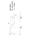
(1)電子式電力量計の電源電圧の変化をエッジ検出して割込機能に割り当てる事により、復電時の電源電圧の上昇によってCPUを通常動作モードに復帰させる。図3はこの一例を示したもので、通電時の電源電圧とバックアップ電源電圧の間に停電/通電検出基準電圧が設定され、停電から復電時に電源電圧が変化してこの基準電圧を超える(P2点を超える)と信号がCPUに入力される。この信号によりCPUは復帰動作する(例えば、特許文献1参照)。尚、P1点は、停電を検知して割込信号を発生する点となっている。
(2)商用電源の交流周波数信号のエッジを検出して割込機能に割り当てることにより、復電以降は商用周波数に同期した割込が常に発生し、CPUを通常状態に戻す。図4はこの一例を示したもので、停電/復帰時の商用電源波形と、この交流波形を基に生成したCPU入力信号波形を示している。このCPU入力波形のP3点、P4点・・がCPUの割込機能により検知されて復帰動作する。
However, since the CPU is in a low power consumption state with limited functions when power is restored, the following method using the interrupt function of the CPU is generally widely used as a trigger to return to the normal state. Has been.
(1) By detecting the edge of the power supply voltage of the electronic watt-hour meter and assigning it to the interrupt function, the CPU is returned to the normal operation mode by the increase of the power supply voltage at the time of power recovery. FIG. 3 shows an example of this. A power failure / energization detection reference voltage is set between the power supply voltage during energization and the backup power supply voltage, and the power supply voltage changes and exceeds this reference voltage when power is restored from the power failure ( A signal is input to the CPU. With this signal, the CPU returns (see, for example, Patent Document 1). In addition, P1 point is a point which detects a power failure and generates an interrupt signal.
(2) By detecting the edge of the AC frequency signal of the commercial power supply and assigning it to the interrupt function, an interrupt synchronized with the commercial frequency is always generated after power recovery, and the CPU is returned to the normal state. FIG. 4 shows an example of this, and shows a commercial power source waveform at the time of power failure / recovery and a CPU input signal waveform generated based on this AC waveform. The P3 point, P4 point,... Of this CPU input waveform are detected by the CPU interrupt function and return operation is performed.
しかし、上記(1)の方法では、電源電圧の変化は復電の際1回しか割込信号が発生しないため、この一度切りの検出を逸すると、次の停電・復電が発生するまでCPUは低消費電力モードから復帰しない。こうなると、その間電力測定は行われず、電力量計としての機能を発揮できない。一方、(2)の方法は、復電以降は常にエッジが発生して割込が入るため、一度エッジ検出をミスしても、直ぐに次の波のエッジによって復電処理を行うことができ、(1)の欠点を補うことができる。しかし、商用電源の交流波をCPUの入力レベルに変換する変換回路を設ける必要があり、その回路に不具合が生じれば確実な復電処理を行うことができない。 However, in the method of (1) above, since the power supply voltage change generates an interrupt signal only once at the time of power recovery, if this once-off detection is missed, the CPU will continue until the next power failure / power recovery occurs. Does not return from the low power consumption mode. In this case, power measurement is not performed during that time, and the function as a watt hour meter cannot be exhibited. On the other hand, in the method (2), since an edge always occurs and interrupts after power recovery, even if the edge detection is missed once, power recovery processing can be performed immediately by the next wave edge. The defect of (1) can be compensated. However, it is necessary to provide a conversion circuit that converts the AC wave of the commercial power source into the input level of the CPU. If a malfunction occurs in the circuit, reliable power recovery processing cannot be performed.
そこで、本発明はこのような問題点に鑑み、復電した際に確実にCPUが通常動作モードに復帰して電力量の計測を開始する電子式電力量計を提供することを目的とする。 SUMMARY OF THE INVENTION In view of the above problems, an object of the present invention is to provide an electronic watt-hour meter that reliably returns a CPU to a normal operation mode and starts measuring power when power is restored.
上記課題を解決する為に、請求項1に記載の発明は、無負荷時にはパルス信号を発生せず、電力に比例した周波数のパルス信号を発生させる電力演算回路と、前記パルス信号から電力量を演算するCPUとを有し、前記CPUは停電時に低消費電力モードに遷移してバックアップ電源により低消費電力動作する電子式電力量計において、前記CPUは、低消費電力モード状態で前記パルス信号を検知したら、通常動作モードに復帰することを特徴とする。
この構成によれば、別途復電検出のための回路を設けること無く、CPUは通常動作モードに復帰する。そして、復電時の1回目のパルス信号のエッジを検出できなくても、直ぐに発生する2回目のパルスのエッジを検出することで確実に且つ遅滞なく低消費電力モードから復帰でき、停電があっても通電後は速やかに電力量の計測を継続できる。また、無負荷時にはパルス信号を発生しない従来の電力演算回路をそのまま使用できる。
In order to solve the above problems, the invention according to claim 1 is directed to a power calculation circuit that generates a pulse signal having a frequency proportional to power without generating a pulse signal when there is no load, and a power amount from the pulse signal. In an electronic watt-hour meter that operates in a low power consumption mode by a backup power source upon a power failure, the CPU outputs the pulse signal in the low power consumption mode state. If detected, it returns to the normal operation mode.
According to this configuration, the CPU returns to the normal operation mode without separately providing a circuit for detecting power recovery. Even if the edge of the first pulse signal at the time of power recovery cannot be detected, it is possible to recover from the low power consumption mode reliably and without delay by detecting the edge of the second pulse that occurs immediately, and there is a power failure. Even after energization, the measurement of electric energy can be continued immediately. Further, a conventional power calculation circuit that does not generate a pulse signal when there is no load can be used as it is.
請求項2の発明は、請求項1に記載の発明において、CPU駆動電圧の低下、或いは被測定電路の電源周波数信号の停止を受けて、CPUは停電を検知して低消費電力モードに遷移することを特徴とする。
この構成によれば、停電の検知はパルス信号で行わないので、パルス信号が発生されなくても無負荷状態と停電を混同することがなく、停電の時のみCPUは低消費電力モードに遷移する。
According to a second aspect of the invention, in the first aspect of the invention, the CPU detects a power failure and transitions to a low power consumption mode upon receiving a decrease in the CPU drive voltage or a stop of the power frequency signal of the circuit under test. It is characterized by that.
According to this configuration, since the power failure is not detected by a pulse signal, the no-load state and the power failure are not confused even if the pulse signal is not generated, and the CPU transits to the low power consumption mode only at the time of the power failure. .
本発明によれば、電源復帰の1回目のパルス信号を検出できなくても、直ぐに発生する2回目のパルスを検出することで確実に且つ遅滞なく低消費電力モードから復帰でき、停電があっても正確な電力量の計測を実施できる。 According to the present invention, even if the first pulse signal for power recovery cannot be detected, it is possible to recover from the low power consumption mode reliably and without delay by detecting the second pulse that occurs immediately, and there is a power failure. Can accurately measure the amount of power.
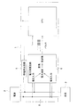
以下、本発明を具体化した実施の形態を、図面に基づいて詳細に説明する。図1は本発明に係る電子式電力量計の一例を示す構成図であり、1は電子式電力量計、2は商用電源、3は負荷を示している。電子式電力量計1は、停電検出回路5と、被測定電路8の電力を演算する電力演算回路6と、電力演算回路6から出力された電力データを基に電力量を演算し、図示しない記憶部に演算した電力量データを記憶操作するCPU7とを備えている。
DESCRIPTION OF EXEMPLARY EMBODIMENTS Hereinafter, embodiments of the invention will be described in detail with reference to the drawings. FIG. 1 is a block diagram showing an example of an electronic watt-hour meter according to the present invention, wherein 1 is an electronic watt-hour meter, 2 is a commercial power source, and 3 is a load. The electronic watt-hour meter 1 calculates the amount of power based on the power
停電検出回路5は、被測定電路8から電子式電力量計1の駆動電圧を生成する図示しない電源回路に設けた電圧検出回路であり、検出した電圧信号をCPU7に出力する従来の停電検出回路となっている。
The power
電力演算回路6は、被測定電路8から電圧情報及び電流情報を入手して電力を演算し、その大きさに比例した周波数のパルス信号をCPU7に出力する。図2はこの電力演算回路6の出力パルス信号を示し、電力が通電されている間はパルス信号を出力し、停電或いは消費電力がゼロ(無負荷)の場合はパルス信号は出力されない。
The
CPU7は、このパルス信号のエッジを検出して電力量を演算し、演算結果を図示しない電力量データ記憶部に記憶させる。パルス信号を受信し続けている間は、この通常動作モードでの動作を続ける。そして、停電検出回路5からの情報により停電が検出されると、低消費電力モードに遷移して別途設けられているバックアップ電源により機能が制限された低電力状態で制御が継続される。
そして、低消費電力モードにおいても、CPUは割込機能が能動状態にあり、パルス信号による割込が入ったら通常動作モードに復帰動作するようプログラムされている。その結果、停電が復電して被測定電路8に電流が流れてパルス信号が生成されたら、この信号を受けてCPUは通常動作モードに復帰して電力量の演算や記憶操作等を再開する。
The
Even in the low power consumption mode, the CPU has an interrupt function active and is programmed to return to the normal operation mode when an interrupt by a pulse signal occurs. As a result, when the power failure is restored and a current flows through the
このように、別途復電検出のための回路を設けること無く、CPUは通常動作モードに復帰する。そして、パルス信号は連続して生成されるので、復電時の1回目のパルス信号のエッジを検出できなくても、直ぐに発生する2回目のパルスのエッジを検出することで確実に且つ遅滞なく低消費電力モードから復帰でき、停電があっても通電後は速やかに電力量の計測を継続できる。また、無負荷時にはパルス信号を発生しない従来の電力演算回路をそのまま使用できる。
更に、パルス信号が発生されなくても無負荷状態と停電を混同することがなく、停電の時のみCPUは低消費電力モードに遷移する。
Thus, the CPU returns to the normal operation mode without providing a circuit for detecting power recovery separately. Since the pulse signal is continuously generated, even if the edge of the first pulse signal at the time of power recovery cannot be detected, the edge of the second pulse that occurs immediately can be detected reliably and without delay. It is possible to return from the low power consumption mode, and even after a power failure, the measurement of electric energy can be continued immediately after energization. Further, a conventional power calculation circuit that does not generate a pulse signal when there is no load can be used as it is.
Further, even if a pulse signal is not generated, the no-load state and power failure are not confused, and the CPU transitions to the low power consumption mode only at the time of power failure.
尚、上記実施形態では、停電検出回路5を被測定電路8の交流電圧から得た直流電圧を監視する電圧検出回路としているが、被測定電路8の交流波を検知して、周波数信号をCPU7に出力する回路としても良い。また、復電の検出は、停電検出回路5から出力される電圧信号の復電時の変化も合わせて二重で復電検出を行っても良い。
In the above embodiment, the power
5・・停電検出回路、6・・電力演算回路、7・・CPU、8・・被測定電路。 5 .... Power failure detection circuit, 6 .... Power calculation circuit, 7 .... CPU, 8 .... Measured circuit.
Claims (2)
前記CPUは、低消費電力モード状態で前記パルス信号を検知したら、通常動作モードに復帰することを特徴とする電子式電力量計。 It has a power calculation circuit that generates a pulse signal having a frequency proportional to power without generating a pulse signal when there is no load, and a CPU that calculates the amount of power from the pulse signal, and the CPU is in a low power consumption mode during a power failure In the electronic watt-hour meter operating at low power consumption by the backup power supply
When the CPU detects the pulse signal in the low power consumption mode state, the CPU returns to the normal operation mode.
Priority Applications (1)
| Application Number | Priority Date | Filing Date | Title |
|---|---|---|---|
| JP2007103052A JP2008261663A (en) | 2007-04-10 | 2007-04-10 | Electronic energy meter |
Applications Claiming Priority (1)
| Application Number | Priority Date | Filing Date | Title |
|---|---|---|---|
| JP2007103052A JP2008261663A (en) | 2007-04-10 | 2007-04-10 | Electronic energy meter |
Publications (1)
| Publication Number | Publication Date |
|---|---|
| JP2008261663A true JP2008261663A (en) | 2008-10-30 |
Family
ID=39984260
Family Applications (1)
| Application Number | Title | Priority Date | Filing Date |
|---|---|---|---|
| JP2007103052A Pending JP2008261663A (en) | 2007-04-10 | 2007-04-10 | Electronic energy meter |
Country Status (1)
| Country | Link |
|---|---|
| JP (1) | JP2008261663A (en) |
Cited By (4)
| Publication number | Priority date | Publication date | Assignee | Title |
|---|---|---|---|---|
| CN103076473A (en) * | 2012-12-17 | 2013-05-01 | 宁波三星电气股份有限公司 | Electric energy meter |
| WO2019216512A1 (en) * | 2018-05-08 | 2019-11-14 | Jeong Yeon Moon | Electronic electricity meter |
| WO2020136905A1 (en) * | 2018-12-28 | 2020-07-02 | 三菱電機株式会社 | Electronic electricity meter |
| CN115190976A (en) * | 2020-12-23 | 2022-10-14 | 西门子股份公司 | Method, device and system for evaluating residual life of element, functional module and system |
-
2007
- 2007-04-10 JP JP2007103052A patent/JP2008261663A/en active Pending
Cited By (6)
| Publication number | Priority date | Publication date | Assignee | Title |
|---|---|---|---|---|
| CN103076473A (en) * | 2012-12-17 | 2013-05-01 | 宁波三星电气股份有限公司 | Electric energy meter |
| WO2019216512A1 (en) * | 2018-05-08 | 2019-11-14 | Jeong Yeon Moon | Electronic electricity meter |
| US11493544B2 (en) | 2018-05-08 | 2022-11-08 | Yeon Moon Jeong | Electronic electricity meter |
| WO2020136905A1 (en) * | 2018-12-28 | 2020-07-02 | 三菱電機株式会社 | Electronic electricity meter |
| JPWO2020136905A1 (en) * | 2018-12-28 | 2021-05-20 | 三菱電機株式会社 | Electronic watt-hour meter |
| CN115190976A (en) * | 2020-12-23 | 2022-10-14 | 西门子股份公司 | Method, device and system for evaluating residual life of element, functional module and system |
Similar Documents
| Publication | Publication Date | Title |
|---|---|---|
| CN104777888B (en) | Coordinate the energy consumption in control reduction computer system by the software and hardware of more power supplys | |
| JP5855699B2 (en) | Motor driving device having welding detection function of magnetic contactor | |
| JP2008261663A (en) | Electronic energy meter | |
| EP2799948B1 (en) | Power supply device and power supply switching method | |
| JP5219251B2 (en) | Electricity meter | |
| US10018685B2 (en) | Method for operating a magnetic field detector circuit and a magnetic field detector circuit | |
| JPH1151985A (en) | Power failure detection device and arithmetic processing device | |
| JP7063692B2 (en) | Watchdog timer monitoring system | |
| JP2012220330A (en) | Distributed power generating system | |
| JP3664692B2 (en) | Arithmetic processing unit | |
| JP2008286673A (en) | Power failure detection circuit, power failure detection method, and power supply system | |
| WO2012081242A1 (en) | Portable electronic device | |
| JP2003319561A (en) | Power generation system | |
| JP4913458B2 (en) | measuring device | |
| JP2004135392A (en) | Three-phase power open phase detector | |
| JP2008128897A (en) | Power supply device | |
| JP4344286B2 (en) | Voltage abnormality detector | |
| JP2017116480A (en) | Watthour meter | |
| JP2011226937A (en) | Pulse detecting equipment | |
| JP5509132B2 (en) | Electromagnetic flow meter | |
| JP4973547B2 (en) | Fault display circuit, information processing apparatus, and fault display method | |
| JP6322378B2 (en) | Detection device | |
| JP5953528B2 (en) | Power strip | |
| JP4248963B2 (en) | Timing device | |
| JP7469110B2 (en) | Uninterruptible power system |