JP2008249729A - Device for measuring frequency - Google Patents
Device for measuring frequency Download PDFInfo
- Publication number
- JP2008249729A JP2008249729A JP2008176520A JP2008176520A JP2008249729A JP 2008249729 A JP2008249729 A JP 2008249729A JP 2008176520 A JP2008176520 A JP 2008176520A JP 2008176520 A JP2008176520 A JP 2008176520A JP 2008249729 A JP2008249729 A JP 2008249729A
- Authority
- JP
- Japan
- Prior art keywords
- frequency
- rotation vector
- value
- signal
- angular velocity
- Prior art date
- Legal status (The legal status is an assumption and is not a legal conclusion. Google has not performed a legal analysis and makes no representation as to the accuracy of the status listed.)
- Pending
Links
- 239000013598 vector Substances 0.000 claims abstract description 197
- 230000002441 reversible effect Effects 0.000 claims abstract description 44
- 238000001514 detection method Methods 0.000 claims abstract description 37
- 238000005070 sampling Methods 0.000 claims abstract description 34
- 238000005259 measurement Methods 0.000 claims abstract description 14
- 230000008859 change Effects 0.000 claims description 42
- 238000004364 calculation method Methods 0.000 claims description 40
- 238000012545 processing Methods 0.000 claims description 25
- 238000012937 correction Methods 0.000 claims description 21
- 238000003079 width control Methods 0.000 claims description 17
- 238000000605 extraction Methods 0.000 claims description 4
- 230000010354 integration Effects 0.000 claims description 4
- 239000013078 crystal Substances 0.000 abstract description 50
- 230000010355 oscillation Effects 0.000 abstract description 28
- 238000000034 method Methods 0.000 description 23
- 239000000126 substance Substances 0.000 description 17
- 238000001179 sorption measurement Methods 0.000 description 10
- 238000010586 diagram Methods 0.000 description 9
- 239000002904 solvent Substances 0.000 description 9
- 239000003344 environmental pollutant Substances 0.000 description 8
- 230000008569 process Effects 0.000 description 8
- 239000013076 target substance Substances 0.000 description 8
- KVGZZAHHUNAVKZ-UHFFFAOYSA-N 1,4-Dioxin Chemical compound O1C=COC=C1 KVGZZAHHUNAVKZ-UHFFFAOYSA-N 0.000 description 7
- 238000012935 Averaging Methods 0.000 description 7
- 239000010453 quartz Substances 0.000 description 7
- 230000009467 reduction Effects 0.000 description 7
- VYPSYNLAJGMNEJ-UHFFFAOYSA-N silicon dioxide Inorganic materials O=[Si]=O VYPSYNLAJGMNEJ-UHFFFAOYSA-N 0.000 description 7
- 238000004458 analytical method Methods 0.000 description 5
- 238000006243 chemical reaction Methods 0.000 description 5
- 230000000694 effects Effects 0.000 description 4
- 230000014509 gene expression Effects 0.000 description 4
- 238000012360 testing method Methods 0.000 description 4
- 231100000719 pollutant Toxicity 0.000 description 3
- 238000001228 spectrum Methods 0.000 description 3
- 239000013077 target material Substances 0.000 description 3
- XLYOFNOQVPJJNP-UHFFFAOYSA-N water Substances O XLYOFNOQVPJJNP-UHFFFAOYSA-N 0.000 description 3
- 238000002965 ELISA Methods 0.000 description 2
- 230000009471 action Effects 0.000 description 2
- 238000011088 calibration curve Methods 0.000 description 2
- 239000007788 liquid Substances 0.000 description 2
- 239000012488 sample solution Substances 0.000 description 2
- 230000002123 temporal effect Effects 0.000 description 2
- 102000004190 Enzymes Human genes 0.000 description 1
- 108090000790 Enzymes Proteins 0.000 description 1
- DYAHQFWOVKZOOW-UHFFFAOYSA-N Sarin Chemical compound CC(C)OP(C)(F)=O DYAHQFWOVKZOOW-UHFFFAOYSA-N 0.000 description 1
- 241000700605 Viruses Species 0.000 description 1
- 230000008901 benefit Effects 0.000 description 1
- 230000005540 biological transmission Effects 0.000 description 1
- 239000000356 contaminant Substances 0.000 description 1
- 238000007796 conventional method Methods 0.000 description 1
- 230000003247 decreasing effect Effects 0.000 description 1
- 150000002013 dioxins Chemical class 0.000 description 1
- 238000011156 evaluation Methods 0.000 description 1
- 238000002474 experimental method Methods 0.000 description 1
- 230000006870 function Effects 0.000 description 1
- 238000003018 immunoassay Methods 0.000 description 1
- 230000001771 impaired effect Effects 0.000 description 1
- 238000011835 investigation Methods 0.000 description 1
- 238000004519 manufacturing process Methods 0.000 description 1
- 238000012067 mathematical method Methods 0.000 description 1
- 238000000691 measurement method Methods 0.000 description 1
- 235000019645 odor Nutrition 0.000 description 1
- 239000003208 petroleum Substances 0.000 description 1
- 231100000614 poison Toxicity 0.000 description 1
- 230000007096 poisonous effect Effects 0.000 description 1
- 230000010349 pulsation Effects 0.000 description 1
- 238000011946 reduction process Methods 0.000 description 1
- 230000000630 rising effect Effects 0.000 description 1
- 239000000523 sample Substances 0.000 description 1
- 239000004065 semiconductor Substances 0.000 description 1
- 239000000779 smoke Substances 0.000 description 1
- 239000002689 soil Substances 0.000 description 1
- 231100000331 toxic Toxicity 0.000 description 1
- 230000002588 toxic effect Effects 0.000 description 1
- 238000004454 trace mineral analysis Methods 0.000 description 1
Images


Classifications
-
- G—PHYSICS
- G01—MEASURING; TESTING
- G01N—INVESTIGATING OR ANALYSING MATERIALS BY DETERMINING THEIR CHEMICAL OR PHYSICAL PROPERTIES
- G01N11/00—Investigating flow properties of materials, e.g. viscosity, plasticity; Analysing materials by determining flow properties
- G01N11/10—Investigating flow properties of materials, e.g. viscosity, plasticity; Analysing materials by determining flow properties by moving a body within the material
- G01N11/16—Investigating flow properties of materials, e.g. viscosity, plasticity; Analysing materials by determining flow properties by moving a body within the material by measuring damping effect upon oscillatory body
-
- G—PHYSICS
- G01—MEASURING; TESTING
- G01G—WEIGHING
- G01G3/00—Weighing apparatus characterised by the use of elastically-deformable members, e.g. spring balances
- G01G3/12—Weighing apparatus characterised by the use of elastically-deformable members, e.g. spring balances wherein the weighing element is in the form of a solid body stressed by pressure or tension during weighing
- G01G3/13—Weighing apparatus characterised by the use of elastically-deformable members, e.g. spring balances wherein the weighing element is in the form of a solid body stressed by pressure or tension during weighing having piezoelectric or piezoresistive properties
-
- G—PHYSICS
- G01—MEASURING; TESTING
- G01N—INVESTIGATING OR ANALYSING MATERIALS BY DETERMINING THEIR CHEMICAL OR PHYSICAL PROPERTIES
- G01N29/00—Investigating or analysing materials by the use of ultrasonic, sonic or infrasonic waves; Visualisation of the interior of objects by transmitting ultrasonic or sonic waves through the object
- G01N29/02—Analysing fluids
- G01N29/036—Analysing fluids by measuring frequency or resonance of acoustic waves
-
- G—PHYSICS
- G01—MEASURING; TESTING
- G01N—INVESTIGATING OR ANALYSING MATERIALS BY DETERMINING THEIR CHEMICAL OR PHYSICAL PROPERTIES
- G01N29/00—Investigating or analysing materials by the use of ultrasonic, sonic or infrasonic waves; Visualisation of the interior of objects by transmitting ultrasonic or sonic waves through the object
- G01N29/44—Processing the detected response signal, e.g. electronic circuits specially adapted therefor
- G01N29/4472—Mathematical theories or simulation
-
- G—PHYSICS
- G01—MEASURING; TESTING
- G01N—INVESTIGATING OR ANALYSING MATERIALS BY DETERMINING THEIR CHEMICAL OR PHYSICAL PROPERTIES
- G01N2291/00—Indexing codes associated with group G01N29/00
- G01N2291/02—Indexing codes associated with the analysed material
- G01N2291/025—Change of phase or condition
- G01N2291/0256—Adsorption, desorption, surface mass change, e.g. on biosensors
-
- G—PHYSICS
- G01—MEASURING; TESTING
- G01N—INVESTIGATING OR ANALYSING MATERIALS BY DETERMINING THEIR CHEMICAL OR PHYSICAL PROPERTIES
- G01N2291/00—Indexing codes associated with group G01N29/00
- G01N2291/02—Indexing codes associated with the analysed material
- G01N2291/028—Material parameters
- G01N2291/02809—Concentration of a compound, e.g. measured by a surface mass change
Abstract
Description
本発明は、感知対象物を吸着するための吸着層がその表面に形成され、感知対象物の吸着により固有振動数が変わるセンサ用振動子例えば水晶振動子を用い、このセンサ用振動子の固有振動数の変化分に基づいて感知対象物を感知する感知装置に関する。また本発明は、周波数信号の周波数を高精度で測定するための技術に関する。 The present invention uses a sensor vibrator, such as a quartz crystal vibrator, in which an adsorption layer for adsorbing a sensing object is formed on the surface thereof, and the natural frequency changes due to the adsorption of the sensing object. The present invention relates to a sensing device that senses a sensing object based on a change in frequency. The present invention also relates to a technique for measuring the frequency of a frequency signal with high accuracy.
環境保全を図る上で、河川や土壌中における種々の環境汚染物質の濃度を把握する必要に迫られているが、汚染物質によっては極めて微量であっても人体への毒性が強いものもあり、このため微量な汚染物質の計測技術の確立が望まれている。最近注目を集めている汚染物質の一つとしてダイオキシンがあるが、このダイオキシンを測定する手法としては、ガスクロマトグラフ質量分析計を用いる方法及びELISA法(適用酵素免疫測定法)が知られている。ガスクロマトグラフ質量分析計によれば、10−12g/mlオーダの高精度な微量分析を行うことができるが、装置価格が極めて高く、このため分析コストも可成り高いものになっており、更に分析に長い期間を必要とするという欠点がある。またELISA法は、ガスクロマトグラフ質量分析計に比べて装置価格、分析価格が低く、分析に要する時間も短いが、分析精度が10−9g/mlオーダと低いという課題がある。 In order to protect the environment, it is necessary to understand the concentration of various environmental pollutants in rivers and soils, but some pollutants are extremely toxic to the human body even in very small amounts. For this reason, establishment of a measurement technique for trace amounts of pollutants is desired. Dioxin is one of the pollutants that has recently attracted attention. As a method for measuring this dioxin, a method using a gas chromatograph mass spectrometer and an ELISA method (applied enzyme immunoassay) are known. According to the gas chromatograph mass spectrometer, it is possible to carry out high-accuracy trace analysis on the order of 10 −12 g / ml, but the price of the apparatus is extremely high, and therefore the analysis cost is considerably high. There is a disadvantage that the analysis requires a long period of time. In addition, the ELISA method is lower in apparatus price and analysis price than the gas chromatograph mass spectrometer and has a short analysis time, but has a problem that the analysis accuracy is as low as 10 −9 g / ml.
そこで本発明者は、感知対象物が水晶振動子に付着するとその固有振動数がその付着量に応じて変化することから、ダイオキシンなどの汚染物質の測定装置として水晶振動子に着眼している。一方、水晶振動子を用いた化学センシング装置として特許文献1に記載された技術がある。この装置は、センサ振動子の発振周波数と基準振動子で発生させた基準周波数との差周波数の絶対値を出力させるサンプリング回路と、差周波数を所要の分周比で分周する分周回路と、その分周出力の周期を基準周波数の周期をクロックとしてカウントするカウンタと、カウントされた周期を基にセンサ振動子の発振周波数を求める演算装置とを備えた構成であり、吸着ガスの同定を行うためのものである。この化学センシング装置によれば、差周波数を求めるようにしているので、測定すべき周波数の絶対値を小さくでき、測定範囲を広げることなく分解能の高い測定が可能になる利点がある。
Therefore, the present inventor focuses on the crystal resonator as a measuring device for contaminants such as dioxin since the natural frequency changes according to the amount of the object to be detected attached to the crystal resonator. On the other hand, there is a technique described in
しかしながら特許文献1の技術は、分周回路を用いることによりカウンタのクロック周波数を低くするようにしており、このため前記差周波数が高いと分周回路の段数が多くなり、その段数が多くなると位相雑音が増大することから、前記差周波数は現実的にはあまり高くできず、従って高い測定精度を確保することが困難であるという課題がある。この結果適用範囲が限定され、ダイオキシンなどのように極めて微量な物質を高い精度で検出することが要求される場合には適用し難い。またカウンタを用いていることから、分解能を高くしようとすると測定時間が長くなる欠点もある。
However, the technique of
本発明はこのような事情の下になされたものであり、その目的は、微量に存在する例えば環境汚染物質などの感知対象物を高い精度をもって検出することのできる感知装置を提供することにある。他の目的は、感知対象物を高い精度をもってかつ瞬時に検出することのできる感知装置を提供することにある。更にまた他の目的は、感知対象物を高い精度をもって検出するにあたり、測定レンジを広げることのできる感知装置を提供することにある。更に他の目的は、周波数信号の周波数を高い精度で測定できる周波数測定装置を提供することにある。 The present invention has been made under such circumstances, and an object of the present invention is to provide a sensing device capable of detecting a sensing object such as an environmental pollutant present in a minute amount with high accuracy. . Another object is to provide a sensing device capable of instantaneously detecting a sensing object with high accuracy. Still another object of the present invention is to provide a sensing device that can widen the measurement range when detecting a sensing object with high accuracy. Still another object is to provide a frequency measuring device capable of measuring the frequency of a frequency signal with high accuracy.
本発明は、周波数信号の周波数を測定する周波数測定装置において、
周波数信号をサンプリングするためのクロック信号を発生させる基準クロック発生部と、
前記周波数信号を前記基準クロック発生部からのクロック信号によりサンプリングしてそのサンプリング値をディジタル信号として出力するアナログ/ディジタル変換部と、
このアナログ/ディジタル変換部からの出力信号に対応する周波数信号に対してディジタル信号による直交検波を行い、当該周波数信号における周波数と直交検波に用いたディジタル信号により特定される周波数との周波数差に相当する角速度で回転する回転ベクトルを複素表示したときの実数部分及び虚数部分を取り出す回転ベクトル取り出し手段と、
この回転ベクトル取り出し手段で得られた前記実数部分及び虚数部分の各時系列データに基づいて、回転ベクトルの角速度を求める回転ベクトル速度演算手段と、を備えたことを特徴とする。
The present invention relates to a frequency measuring device that measures the frequency of a frequency signal.
A reference clock generator for generating a clock signal for sampling the frequency signal;
An analog / digital converter that samples the frequency signal with a clock signal from the reference clock generator and outputs the sampled value as a digital signal;
Corresponds to the frequency difference between the frequency of the frequency signal corresponding to the output signal from the analog / digital converter and the frequency specified by the digital signal used for the quadrature detection. Rotation vector extracting means for extracting a real part and an imaginary part when a rotation vector rotating at an angular velocity is displayed in a complex manner;
Rotation vector speed calculating means for obtaining an angular speed of the rotation vector based on the time-series data of the real part and the imaginary part obtained by the rotation vector extracting means.
前記回転ベクトル取り出し手段は、アナログ/ディジタル変換部からの出力信号に対応する周波数信号を直交検波する手段と、この手段で得られたデータに含まれる高周波成分を除去する手段と、を含む構成とすることができる。またあるタイミングにおける前記サンプリング値に対応する実数部分及び虚数部分を夫々I(n)及びQ(n)とし、当該タイミングよりも前のタイミングにおける前記サンプリング値に対応する実数部分及び虚数部分を夫々I(n−1)及びQ(n−1)とすると、前記回転ベクトル速度演算手段は、{Q(n)−Q(n−1)}・I(n)−{I(n)−I(n−1)}・Q(n)の演算に基づいて周波数の変化量を求める手段として構成することができる。 The rotation vector extracting means includes means for orthogonally detecting a frequency signal corresponding to the output signal from the analog / digital converter, and means for removing a high frequency component contained in the data obtained by the means. can do. Also, let the real part and imaginary part corresponding to the sampling value at a certain timing be I (n) and Q (n), respectively, and let the real part and imaginary part corresponding to the sampling value at a timing before that timing be I Assuming (n-1) and Q (n-1), the rotation vector speed calculation means is {Q (n) -Q (n-1)}. I (n)-{I (n) -I ( n-1)} · Q (n) based on the calculation of the frequency change amount.
前記回転ベクトル速度演算手段は、前記演算の演算結果に対して所定時間内の平均値を求める手段を備えている構成とすることができ、より具体的な一例としては、移動平均を求める手段として構成される。また前記回転ベクトル速度演算手段の前段に、前記実数部分及び虚数部分を、これら実数部分及び虚数部分により決定されるベクトルのスカラー量により割り算する補正処理部を設けることが好ましい。 The rotation vector speed calculation means can be configured to include means for obtaining an average value within a predetermined time with respect to the calculation result of the calculation. As a more specific example, as a means for obtaining a moving average Composed. Further, it is preferable that a correction processing unit for dividing the real part and the imaginary part by a scalar quantity of a vector determined by the real part and the imaginary part is provided in the preceding stage of the rotation vector speed calculation means.
更に本発明は、次のように構成することが好ましい。即ち、前記回転ベクトル速度演算手段により求められた周波数の変化量に相当する角速度で、前記回転ベクトルとは逆向きに回転する逆回転ベクトルを複素表示したときの実数部分及び虚数部分を作成する逆回転ベクトル生成部と、
前記回転ベクトル速度演算手段の前段に設けられ、前記回転ベクトル取り出し手段により得られた前記回転ベクトルの実数部分及び虚数部分と、前記逆回転ベクトル生成部により生成された逆回転ベクトルの実数部分及び虚数部分と、を演算して前記回転ベクトルの角速度を遅くすることにより、周波数の変化分のレンジを補正する周波数レンジ補正部と、を更に備えた構成とする。
Further, the present invention is preferably configured as follows. That is, an inverse that creates a real part and an imaginary part when a reverse rotation vector that rotates in the opposite direction to the rotation vector is displayed in a complex manner at an angular velocity corresponding to the amount of change in frequency obtained by the rotation vector speed calculation means. A rotation vector generation unit;
A real part and an imaginary part of the rotation vector provided by the rotation vector extraction means provided in the preceding stage of the rotation vector speed calculation means, and a real part and an imaginary number of the reverse rotation vector generated by the reverse rotation vector generation unit And a frequency range correction unit that corrects a range corresponding to a change in frequency by calculating the portion and slowing the angular velocity of the rotation vector.
この場合、逆回転ベクトル生成部は、複素表面上における逆回転ベクトルの位置を規定する実数部分及び虚数部分の組を回転方向に沿って順番に配列したデータテーブルと、前記周波数の変化量に相当するインクリメント数またはデクリメント数により前記データテーブルのアドレスを発生させることにより逆回転ベクトルを生成するアドレス制御部と、を備えた構成とすることができる。より具体的な例としては、逆回転ベクトル生成部は、前記回転ベクトル速度演算手段により求められた周波数の変化量をディジタル信号で表したときの下位ビットの値に応じたデューティ比のパルス列を出力するパルス幅制御部と、前記周波数の変化量をディジタル信号で表したときの上位ビットの値と前記パルス幅制御部により作成されたパルスのレベルとを加算して前記アドレス制御部に出力する加算部と、を備え、
前記アドレス生成部は、この加算部からの出力値を積分し、この積分値を前記データテーブルのアドレスとする構成を挙げることができる。
In this case, the reverse rotation vector generation unit corresponds to a data table in which a set of a real part and an imaginary part defining the position of the reverse rotation vector on the complex surface is arranged in order along the rotation direction, and the amount of change in the frequency. And an address control unit that generates a reverse rotation vector by generating an address of the data table based on the increment number or the decrement number. As a more specific example, the reverse rotation vector generation unit outputs a pulse train having a duty ratio corresponding to the value of the lower bits when the amount of change in frequency obtained by the rotation vector speed calculation means is represented by a digital signal. A pulse width control unit that adds the value of the high-order bit when the amount of change in the frequency is represented by a digital signal and the level of the pulse created by the pulse width control unit and outputs the result to the address control unit And comprising
The address generation unit can integrate the output value from the addition unit and use the integration value as the address of the data table.
本発明は、例えば水晶振動子などのセンサ用振動子からの周波数信号を基準クロック発生部からのクロック信号によりサンプリングしてそのサンプリング値をディジタル信号として出力し、この出力信号に対応する周波数信号に対してディジタル信号による直交検波を行い、前記サンプリング値により特定される周波数信号(アナログ/ディジタル変換部の出力信号)の周波数と直交検波に用いたデイジタル信号により特定される周波数との差に相当する周波数で回転する回転ベクトルを取り出している。この回転ベクトルの角速度はセンサ用振動子の発振周波数(国有振動数)に対応しているので、例えば純水などの溶媒にセンサ用振動子を浸漬したときの回転ベクトルの角速度とその溶媒に感知対象物を含む液を供給したときの回転ベクトルの角速度とを検出することで、回転ベクトルの角速度の変化分を検出することができ、センサ用振動子に吸着した感知対象物の吸着量を知ることができる。なお本発明では、例えば予め溶媒中における感知対象物の種々の濃度と回転ベクトルの角速度との対応を検量線などにより把握しておくことにより、回転ベクトルの角速度を基に前記検量線などと照らし合わせることにより感知対象物の濃度を推定するようにしてもよい。
このためパルスをカウントして周波数を求める手法に比べてセンサ用振動子の発振周波数を高い精度でしかも極く短時間で検出することができる。従ってまたセンサ用振動子の発振周波数の変化分も高い精度でしかも極く短時間で検出することができ、環境汚染物質をはじめ微量物質を検出する装置として有用なものである。
In the present invention, for example, a frequency signal from a sensor oscillator such as a crystal oscillator is sampled by a clock signal from a reference clock generator, and the sampling value is output as a digital signal. Corresponding to the difference between the frequency of the frequency signal (output signal of the analog / digital converter) specified by the sampling value and the frequency specified by the digital signal used for the quadrature detection, by performing quadrature detection using a digital signal. A rotation vector that rotates at a frequency is extracted. The angular velocity of this rotation vector corresponds to the oscillation frequency (national frequency) of the sensor vibrator. For example, when the sensor vibrator is immersed in a solvent such as pure water, the angular velocity of the rotation vector is detected by that solvent. By detecting the angular velocity of the rotation vector when the liquid containing the object is supplied, the amount of change in the angular velocity of the rotation vector can be detected, and the amount of the sensing object adsorbed on the sensor vibrator is known. be able to. In the present invention, for example, the correspondence between various concentrations of the sensing object in the solvent and the angular velocity of the rotation vector is grasped in advance by using a calibration curve or the like, so that the calibration curve or the like is illuminated based on the angular velocity of the rotation vector. By combining them, the concentration of the sensing object may be estimated.
For this reason, it is possible to detect the oscillation frequency of the sensor vibrator with high accuracy and in a very short time compared with the method of obtaining the frequency by counting pulses. Therefore, the change in the oscillation frequency of the sensor vibrator can be detected with high accuracy and in a very short time, and is useful as a device for detecting trace substances including environmental pollutants.
また前記回転ベクトル速度演算手段により求められた周波数の変化量に相当する角速度で、即ち前記回転ベクトルに対応する角速度で、当該回転ベクトルとは逆向きに回転する逆回転ベクトルを生成し、前記回転ベクトルに逆回転ベクトルを乗算することで、前記回転ベクトルの角速度を遅くすることができる。その結果、センサ用振動子の発振周波数が高くても回転ベクトルの角速度を遅くすることでその角速度を検出することができるから、結果として周波数の測定レンジを広くすることができる。 Further, a reverse rotation vector that rotates in an opposite direction to the rotation vector at an angular velocity corresponding to the amount of change in frequency obtained by the rotation vector velocity calculation means, that is, an angular velocity corresponding to the rotation vector, is generated, and the rotation By multiplying the vector by the reverse rotation vector, the angular velocity of the rotation vector can be reduced. As a result, even if the oscillation frequency of the sensor vibrator is high, the angular velocity can be detected by slowing the angular velocity of the rotation vector. As a result, the frequency measurement range can be widened.
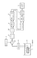
図1は本発明に係る感知装置の実施の形態の全体構成を示す図である。1はセンサ部であり、このセンサ部1はセンサ用振動子である圧電振動子例えば水晶振動子11の一方の面を石英などにより密閉すると共に他方の面が露出していて、感知対象物質が存在する溶液12に例えば浸漬されるランジュバン型振動子として構成されている。前記水晶振動子11における溶液に接触する面には、感知対象物質を吸着(捕獲)するための吸着層、例えばダイオキシンを吸着するための抗体を含む吸着層が形成されている。13は水晶振動子11を発振させる発振回路であり、例えば周波数信号としての正弦波の高周波信号を出力する。
FIG. 1 is a diagram showing an overall configuration of an embodiment of a sensing device according to the present invention.
2は基準クロック発生部であり、発振回路13からの高周波信号をサンプリングするために周波数の安定性が極めて高い周波数信号であるクロック信号を出力する。21はA/D(アナログ/ディジタル)変換器であり、発信回路13からの高周波信号を基準クロック発生部2からのクロック信号によりサンプリングしてそのサンプリング値をディジタル信号として出力する。このディジタル信号で特定される高周波信号は基本波の他に高調波も含まれている。即ち高調波ひずみを有する正弦波をサンプリングする場合、その高調波成分が折り返しの影響を受けて、場合によっては周波数スペクトルにおける周波数軸上で基本波周波数と高調波の周波数とが重なる場合が想定される。そこでこのような重なりを避けて正しい感知動作が得られるようにする必要がある。
一般に周波数f1の正弦波信号を周波数fsのクロック信号でサンプリングした場合、その取り込み結果の周波数f2は(1)式で表される。ただしmod(,)はmodulo関数を表している。 In general, when a sine wave signal having a frequency f1 is sampled with a clock signal having a frequency fs, the frequency f2 obtained as a result of the capture is expressed by equation (1). However, mod (,) represents a modulo function.
f2=|mod(f1+fs/2,fs)−fs/2| ……(1)
この取り込み結果において、基本波周波数に対してn次の高調波の周波数はn×(基本波周波数)として表されるので、これをf2と置いて上記の(1)式に代入すれば、高調波がどのような周波数として取り込まれるかを計算することができる。この計算を用いることにより基本波の周波数と高調波の周波数とが重ならないように、発振回路13からの高周波信号の周波数をfcとサンプリング周波数(クロック信号の周波数)fsとを設定することができ、例えばfcを11MHz、fsを12MHzに設定する。この場合、A/D変換器21からのディジタル信号である出力信号で特定される周波数信号の基本波は1MHzの正弦波となる。なおfc/fsを11/12にすれば、基本波の周波数と高調波の周波数とが重ならないが、fc/fsはこの値に限られるものではない。
f2 = | mod (f1 + fs / 2, fs) −fs / 2 | (1)
In this acquisition result, the frequency of the nth-order harmonic with respect to the fundamental frequency is expressed as n × (fundamental frequency). If this is set as f2 and substituted into the above equation (1), the harmonic It can be calculated as to what frequency the wave is captured. By using this calculation, the frequency of the high frequency signal from the oscillation circuit 13 and the sampling frequency (frequency of the clock signal) fs can be set so that the frequency of the fundamental wave and the frequency of the harmonic do not overlap. For example, fc is set to 11 MHz, and fs is set to 12 MHz. In this case, the fundamental wave of the frequency signal specified by the output signal which is a digital signal from the A /
A/D変換器21の後段には、キャリアリムーブ31及びローパスフィルタ32がこの順に設けられている。キャリアリムーブ31及びローパスフィルタ32は、A/D変換器21からのディジタル信号により特定される例えば1MHzの正弦波信号の周波数と、直交検波に用いられる正弦波信号の周波数との差の周波数で回転する回転ベクトルを取り出すために用いられている。
At the subsequent stage of the A /
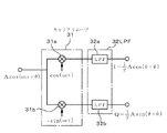
回転ベクトルを取り出す作用をわかりやすく説明するために、A/D変換器21からのディジタル信号により特定される正弦波信号をAcos(ω0t+θ)とする。一方、キャリアリムーブ31は、図2に示すように前記正弦波信号に対してcos(ω0t)を掛け算する掛け算部31aと前記正弦波信号に対して−sin(ω0t)を掛け算する掛け算部31bとを備えている。即ちこのような演算をすることにより直交検波される。掛け算部31aの出力及び掛け算部31bの出力は夫々(2)式及び(3)式により表される。
In order to explain the operation of extracting the rotation vector in an easy-to-understand manner, the sine wave signal specified by the digital signal from the A /
Acos(ω0t+θ)・cos(ω0t)
=1/2・Acosθ+1/2{cos(2ω0t)・cosθ+sin(2ω0t)・sinθ}……(2)
Acos(ω0t+θ)・−sin(ω0t)
=1/2・Asinθ−1/2{sin(2ω0t)・cosθ+cos(2ω0t)・sinθ}……(3)
従って掛け算部31aの出力及び掛け算部31bの出力を夫々ローパスフィルタ32a及び32bを通すことにより、2ω0の周波数信号は除去されるので、結局ローパスフィルタ32からは1/2・Acosθと1/2・Asinθとが取り出される。なおローパスフィルタ32は、ローパスフィルタ32a及び32bから構成されるものとして記載してある。ローパスフィルタ32における実際のディジタル処理は、キャリアリムーブ31から出力される時系列データについて連続する複数個のデータ例えば6個のデータの移動平均を演算している。
Acos (ω0t + θ) ・ cos (ω0t)
= 1/2 · Acosθ + 1/2 {cos (2ω0t) · cosθ + sin (2ω0t) · sinθ} (2)
Acos (ω0t + θ) ・ -sin (ω0t)
= 1/2 · Asinθ-1/2 {sin (2ω0t) · cosθ + cos (2ω0t) · sinθ} (3)
Therefore, by passing the output of the
そしてAcos(ω0t+θ)で表される正弦波信号の周波数が変化すると、Acos(ω0t+θ)はAcos(ω0t+θ+ω1t)となる。ただしω1はω0よりも十分小さいものとする。従って1/2・Acosθは1/2・Acos(θ+ω1t)となり、1/2・Asinθは1/2・Asin(θ+ω1t)となる。即ち、ローパスフィルタ32から得られた出力は、正弦波信号[Acos(ω0t+θ)]の周波数の変化分ω1/2πに対応する信号である。つまりこれらの値は、A/D変換器21からのディジタル信号により特定される正弦波信号の周波数と直交検波に用いた正弦波信号の周波数ω0/2πとの差の周波数で回転する回転するベクトルを複素表示したときの実数部分(I)及び虚数部分(Q)である。
When the frequency of the sine wave signal represented by Acos (ω0t + θ) changes, Acos (ω0t + θ) becomes Acos (ω0t + θ + ω1t). However, ω1 is assumed to be sufficiently smaller than ω0. Accordingly, 1/2 · Acosθ is 1/2 · Acos (θ + ω1t), and 1/2 · Asinθ is 1/2 · Asin (θ + ω1t). That is, the output obtained from the low-
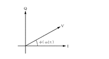
図3はこの回転ベクトルを表した図であり、この回転ベクトルは長さがAであり、角速度がω1である。図2及び図3ではω1tをφとして表している。従って例えば水晶振動子11に感知対象物質が吸着されていないときのA/D変換部21からの周波数信号の周波数がω0/2πであれば、ω1はゼロであるからこの回転ベクトルの角速度はゼロであるが、水晶振動子11に感知対象物質が吸着されて水晶振動子11の周波数が変化し、これにより前記正弦波信号の周波数が変化すると、その変化分に応じた角速度で回転することになる。また水晶振動子11に感知対象物質が吸着されていないときのA/D変換部21からの周波数信号の周波数がω0/2πからずれていれば、そのずれた周波数に応じた角速度で回転ベクトルが回転することになる。いずれにしても回転ベクトルの角速度は、水晶振動子11の発振周波数に対応する値であるから、例えば溶媒中に水晶振動子11を浸漬したときと、その溶媒に感知対象物を加えて感知対象物を水晶振動子11に吸着させたときと、の夫々の回転ベクトル角速度を求めてその角速度差を求めれば、感知対象物を水晶振動子11に吸着させたことによる発振周波数の変化分を知ることができる。
FIG. 3 is a diagram showing the rotation vector. The rotation vector has a length A and an angular velocity ω1. 2 and 3, ω1t is represented as φ. Therefore, for example, if the frequency of the frequency signal from the A /
このようにキャリアリムーブ31は前記正弦波信号に対して直交検波を行い、ローパスフィルタ32はその検波結果に対して高周波成分を除去するものであり、従ってこれらは、A/D変換部21からの周波数信号に対してディジタル信号による直交検波を行い、当該周波数信号における周波数と直交検波に用いた正弦波信号の周波数ω0/2πとの周波数差に相当する角速度で回転する回転ベクトルを複素表示したときの実数部分及び虚数部分を取り出す手段をなすものである。
In this way, the carrier remove 31 performs quadrature detection on the sine wave signal, and the low-
図1に戻って、ローパスフィルタ32の後段には、減数処理部4が設けられている。この減数処理部4は、ローパスフィルタ32から得られる時系列のディジタル信号つまり12MHzのクロック信号により得られるディジタル値の群について、例えば120個おきにデータを取り出す減数処理(間引き処理)を行うものである。このように減数処理することにより、コンピュータの演算の負担が軽くなる。そしてこの実施の形態では後述のように、サンプリング間隔において回転ベクトルがどのくらい回転したかを把握して当該回転ベクトルの角速度を求めるようにしているため、ディジタル値群を多少間引いても前記角速度の検出精度(周波数の変化分の検出精度)には影響を及ぼさない。
Returning to FIG. 1, the
減数処理部4の後段には、補正処理部5が設けられており、この補正処理部5は、ローパスフィルタ32を通りかつ減数処理された前記回転ベクトルの実数部分であるI値と回転ベクトルの虚数部分であるQ値とについて、夫々回転ベクトルのスカラー量で割り算することにより、回転ベクトルの単位長さ当たりのI値及びQ値を求める処理を行う。即ち、回転ベクトルに符号Vを割り当てると、補正処理部5は図4に示すように、I値とQ値とを夫々2乗して加算し、その加算値の平方根を算出して回転ベクトルVのスカラー量|V|を求め、I値及びQ値を|V|で割り算するように構成されている。
A
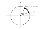
このようにI値及びQ値を補正する理由は次の通りである。この実施の形態では、回転ベクトルVがサンプリング間隔でどれだけ回転したかを算出するにあたり、図5に示すようにn番目のサンプリングにより求めた回転ベクトルV(n)と(n−1)番目のサンプリングにより求めた回転ベクトルV(n−1)とを結ぶベクトルΔVを含む因子により評価している。このため発振回路13からの高周波信号の波形のゆらぎなどにより回転ベクトルがいわば間延びしてΔVがΔV`になってしまうと、ΔVと回転ベクトルの回転量Δφとの対応関係が崩れてしまい、回転ベクトルの角速度の検出値の信頼性を損ねるおそれがある。そこで既述のように補正処理を行うことにより、各タイミングにおけるI値及びQ値が回転ベクトルの単位長さに対応する値として揃えられるので、回転ベクトルの間延びの影響を排除することができる。 The reason for correcting the I value and the Q value in this way is as follows. In this embodiment, in calculating how much the rotation vector V is rotated at the sampling interval, as shown in FIG. 5, the rotation vectors V (n) and (n−1) th obtained by the nth sampling are used. Evaluation is performed by a factor including a vector ΔV connecting the rotation vector V (n−1) obtained by sampling. For this reason, if the rotation vector is extended due to fluctuations in the waveform of the high-frequency signal from the oscillation circuit 13 and ΔV becomes ΔV `, the correspondence between ΔV and the rotation amount Δφ of the rotation vector is lost, and the rotation The reliability of the detected value of the angular velocity of the vector may be impaired. Therefore, by performing the correction process as described above, the I value and the Q value at each timing are aligned as values corresponding to the unit length of the rotation vector, so that it is possible to eliminate the influence of the extension of the rotation vector.
更に図1に示すように前記補正処理部5の後段には、回転ベクトルの角速度を求めるための速度演算部6が設けられている。この速度演算部6について図6及び図7を参照して説明すると、図6に示すように、(n−1)番目のサンプリングにより求めた回転ベクトルV(n−1)とn番目のサンプリングにより求めた回転ベクトルV(n)=V(n−1)+ΔVとのなす角度Δφは、定数をKとすると、回転ベクトルの角速度(周波数)がサンプリング周波数よりも十分に小さければ、(4)式で近似できる。ただしΔφは、V(n)の位相φ(n)とV(n−1)の位相φ(n−1)との差であり、またimagは虚数部分、conj{V(n)}はV(n)の共役ベクトルである。
Further, as shown in FIG. 1, a
Δφ=K・imag[ΔV・conj{V(n)}] ……(4)
ここでI値及びQ値についてn番目のサンプリングに対応する値を夫々I(n)及びQ(n)とすれば、ΔV及びconj{V(n)}は複素表示すると夫々(5)式及び(6)式で表される。
Δφ = K · imag [ΔV · conj {V (n)}] (4)
Here, assuming that the values corresponding to the n-th sampling for the I value and the Q value are I (n) and Q (n), respectively, ΔV and conj {V (n)} are expressed in a complex manner, respectively, (6) It represents with Formula.
ΔV=ΔI+jΔQ ……(5)
conj{V(n)}=I(n)−jQ(n) ……(6)
ただしΔIはI(n)−I(n−1)であり、ΔQはQ(n)−Q(n−1)である。(5)式及び(6)式を(4)式に代入して整理すると、Δφは(7)式で表されることになる。
ΔV = ΔI + jΔQ (5)
conj {V (n)} = I (n) -jQ (n) (6)
However, ΔI is I (n) −I (n−1), and ΔQ is Q (n) −Q (n−1). If the expressions (5) and (6) are substituted into the expression (4) and rearranged, Δφ is expressed by the expression (7).
Δφ=ΔQ・I(n)−ΔI・Q(n) ……(7)
前記速度演算部6は、この(7)式の演算を行ってΔφの近似値を求めるものであり、その構成は図7に示す通りである。速度演算部6に入力されたI値がn番目のサンプリングに対応する値であるI(n)であるとすると、レジスタ61には、一つ前のタイミングである(n−1)番目のサンプリングに対応するI(n−1)が保持されており、これらが突き合わせ回路部62で突き合わされてI(n)とI(n−1)との差分ΔIが取り出され、I(n)及びΔIが演算部65に入力される。またQ値についてもレジスタ63及び突き合わせ回路部64により同様に処理されてQ(n)及びΔQが演算部65に入力される。そして演算部65では、(7)式の演算を行ってΔφを求める。詳しくは演算部65の演算結果はΔφとして評価したものである。
Δφ = ΔQ · I (n) −ΔI · Q (n) (7)
The
ここで回転ベクトルV(n−1)とV(n)とが求まればこの間の角度Δφを求める手法あるいは評価する手法は種々の数学的手法を使うことができ、その一例として(4)式の近似式を挙げたに過ぎない。その数式としてはV(n)とV(n−1)の各終点を結ぶ線の中点と原点とを結ぶベクトルVOである{V(n)+V(n−1)}/2を用い、(4)式においてV(n)に代えてこのベクトルVOを代入してもよい。このような(4)式が近似できる理由は、VOとΔVとが直交しているとみなすことができ、このためΔVの長さは、VOを実軸と見たてたときのΔVの虚数値に相当すると取り扱えられるからである。そしてΔφを求める手法として直感的に分かりやすい方法は、argV(n)及びargV(n−1)を求めて差し引けばよいが、この場合には各ベクトルの虚数値と実数値との組とそのベクトルの位相φとを対応付けたテーブルが必要になるので、既述の(4)式に基づいて演算を行う方がコンピュータの負荷という点で得策である。なおargV(n)はtan-1(虚数値/実数値)である。 If the rotation vectors V (n−1) and V (n) are obtained here, various mathematical methods can be used as a method for obtaining or evaluating the angle Δφ therebetween. This is just an approximate expression. As the mathematical formula, {V (n) + V (n-1)} / 2 which is a vector VO connecting the midpoint of the line connecting the end points of V (n) and V (n-1) and the origin is used. In the equation (4), this vector VO may be substituted for V (n). The reason why the equation (4) can be approximated can be considered that VO and ΔV are orthogonal to each other. For this reason, the length of ΔV is the imaginary value of ΔV when VO is regarded as a real axis. This is because it can be handled if it corresponds to a numerical value. An intuitively easy-to-understand method for obtaining Δφ is to obtain and subtract argV (n) and argV (n−1). In this case, a set of imaginary values and real values of each vector Since a table in which the phase φ of the vector is associated is required, it is better to perform the calculation based on the above-described equation (4) in terms of the load on the computer. Note that argV (n) is tan −1 (imaginary value / real value).
この速度演算部6の後段には、図1に示すように、時間平均化処理部7が設けられており、時間平均化処理部7は、速度演算部6で得られた演算結果であるΔφの時系列データについて時間的な平均化処理、例えば所定数のデータの移動平均を取り出して出力する。ここで得られた出力値は周波数差検出部71に入力される。この周波数差検出部71は、
第1の環境である例えば純水などの溶媒中に水晶振動子11を置いたときの回転ベクトルの角速度と、第2の環境である、感知対象物が供給された溶媒中に水晶振動子11を置いたときの回転ベクトルの角速度と、の差を検出するためのものである。回転ベクトルの角速度は、水晶振動子11の発振周波数に対応している値であるため、周波数差検出部71にて検出された角速度検出差は、水晶振動子11が感知物質を吸着したことによる発振周波数の変化分に対応する値であり、感知物質の吸着量を評価した値であるといえる。周波数差検出部71は、より具体的には、各回転ベクトルの角速度を記憶するメモリ、このメモリ内の各回転ベクトルの角速度を読み出してその角速度差を演算する手段などを備えている。
As shown in FIG. 1, a time averaging
The angular velocity of the rotation vector when the
以上のようにこの実施の形態の構成をブロック化して説明したが、実際の演算あるいはデータ処理は、ソフトウエアにより実行される。 As described above, the configuration of this embodiment has been described as a block, but actual computation or data processing is executed by software.
次に上述の実施の形態の作用について説明する。センサ部1の水晶振動子(発振回路13)から発振される、基本波として正弦波を含む例えば11MHzの周波数信号が例えば12MHzの周波数信号によりA/D変換部21で変換され、A/D変換部21からは約1MHzの基本波である正弦波信号を含む信号が出力される。ここで説明の便宜上この正弦波信号をAcos(ω0t+ω1t+θ)とすると(ω1はω0よりも十分小さい)、この正弦波信号が直交検波され更に低周波成分が除去されることにより、当該正弦波信号の周波数の変化量に対応する角速度で回転する回転ベクトルが取り出される。即ち、この回転ベクトルの実数部分及び虚数部分が夫々I値及びQ値として取り出される。これらI値及びQ値は減数処理部4で減数処理され、更に補正処理部5にて回転ベクトルVのスカラー量|V|で割り算されて、回転ベクトルの間延びの影響を取り除き、周波数差演算部6に入力される。なお説明の煩雑さを避けるために補正処理前後の回転ベクトルに対して、同じ符号「V」を付して説明する。
Next, the operation of the above embodiment will be described. For example, a frequency signal of 11 MHz including a sine wave as a fundamental wave, which is oscillated from the crystal resonator (oscillation circuit 13) of the
この回転ベクトルVは、正弦波信号Acos(ω0t+ω1t+θ)の周波数と直交検波に用いた正弦波信号の周波数ω0/2πとの差、つまりω1の角速度で回転するものである(図3参照)。ここで説明をわかりやすくするために、センサ部1を感知対象物質の存在を検出するための溶液内に例えば浸漬し、かつ感知対象物質が存在しないとき(水晶振動子11の検出限界以下のとき)の水晶振動子11の固有振動数に対応する角速度がω0であったとすると、ω1はゼロであるから、回転ベクトルVは静止している。従って時間平均化処理部7の出力であるΔφはゼロである。
This rotation vector V rotates at the difference between the frequency of the sine wave signal Acos (ω0t + ω1t + θ) and the frequency ω0 / 2π of the sine wave signal used for quadrature detection, that is, at the angular velocity of ω1 (see FIG. 3). In order to make the explanation easy to understand, when the
一方前記溶液中に感知対象物質例えばダイオキシンが存在する場合には、水晶振動子11に吸着されたダイオキシンの量に応じてその発振周波数(固有振動数)が変化する。この場合周波数の変化量に対応する角速度で前記回転ベクトルVが回転し始める。説明を簡略化するために仮に周波数の変化量が1Hzであるとすると、回転ベクトルVは1秒間に1回転することになる。ここで本実施の形態では、サンプリングが相前後するV(n)の位相φ(n)とV(n−1)の位相φ(n−1)との差Δφを把握して回転ベクトルの角速度を検出しようとするものであり、このサンプリング間隔が仮に1/100秒であるとすると、Δφは3.6度になる。言い換えればサンプリング間隔の時間だけで回転ベクトルVの角速度が求まり、水晶振動子11の発振周波数の変化量を知ることができるのである。
ところで感知対象物質が存在しないときの水晶振動子11の発振周波数に対応する角速度が直交検波に用いた正弦波信号の角速度に一致することはかなり稀であることから、実際には、感知対象物質が存在しないときの水晶振動子11の発振周波数に対応する回転ベクトルの角速度と感知対象物質が存在するときの水晶振動子11の発振周波数に対応する回転ベクトルの角速度とを夫々求め、その角速度の差が求められる。この回転ベクトルの角速度の差は、水晶振動子11に感知対象物質が吸着したことによる水晶振動子11の周波数の変化分に対応する値であるから、予め感知対象物質の吸着量と周波数の変化分との関係を把握しておくことにより、そのときの感知対象物質の吸着量を求めることができる。そして溶液中における感知対象物質の濃度と感知対象物の吸着量との関係を予め求めておけば、感知対象物質の吸着量つまり水晶振動子11の周波数の変化分に基づいて溶液中の感知対象物質の濃度がわかる。このため水晶振動子11が浸漬されている溶液(図1中の符号12)に供給された試料液中の感知物質の濃度がわかる。
On the other hand, when a sensing target substance such as dioxin is present in the solution, its oscillation frequency (natural frequency) changes according to the amount of dioxin adsorbed on the
By the way, it is quite rare that the angular velocity corresponding to the oscillation frequency of the
このように上述の実施の形態によれば、水晶振動子11の発振周波数(発振回路13からの周波数信号の周波数)をディジタル処理し、回転ベクトルの角速度をサンプリング間隔に応じた位相差により検出している。この結果従来のようにパルスをカウントする手法に比べて水晶振動子11の発振周波数の変化分を後述の実施例にて裏付けられるように高い精度でしかも極く短時間で検出することができる。従来のようなパルスカウントの方法では、正弦波をパルスにしてカウントするため、例えば10MHzのパルスを1Hzの分解能で識別するためには1秒もの時間がかかる。以上の説明から分かるように、本発明は、環境汚染物質をはじめ微量物質を検出する装置として極めて有用なものである。
As described above, according to the above-described embodiment, the oscillation frequency of the crystal unit 11 (the frequency of the frequency signal from the oscillation circuit 13) is digitally processed, and the angular velocity of the rotation vector is detected by the phase difference corresponding to the sampling interval. ing. As a result, it is possible to detect the change in the oscillation frequency of the
本発明の使用方法としては、センサ部1を溶液中に浸漬することに限られず、溶液を水晶振動子11の表面に垂らすようにしてもよく、またダイオキシン以外の環境汚染物質例えばPCBなどを感知するものであってもよいし、あるいはウイルスを感知するものであってもよい。
そして本発明では、例えば水晶振動子11に接触する溶液中の感知対象物質の濃度を種々変えて、予め各濃度と回転ベクトルの角速度との関係を求めておき、水晶振動子11に溶液を接触させたときの回転ベクトルの角速度とこの関係とに基づいて感知対象物質の吸着量を推定するようにしてもよい。
また水晶振動子1を純水などの溶媒に接触させた状態をいわゆるブランク値としてもよいが、水晶振動子1を溶媒に接触させずに大気に晒した状態をブランク値とし、水晶振動子1に溶液を接触させて感知対象物質が吸着したときの回転ベクトルの回転数の変化分を捉えるようにしてもよい。
The method of use of the present invention is not limited to immersing the
In the present invention, for example, the concentration of the substance to be detected in the solution in contact with the
In addition, a state in which the
更にまた本発明は、液体中に存在する物質の感知に限られるものではなく、石油の臭い検知、火災時の煙検知、あるいはサリンガスなどの毒ガスの検知、部品内のガスの検知、半導体製造工場などのクリーンルーム内のガスの検知など種々の分野にて適用できる。 Furthermore, the present invention is not limited to the detection of substances present in the liquid, but it can detect petroleum odors, smoke detection in the event of fire, or poisonous gas such as sarin gas, gas in parts, semiconductor manufacturing plant It can be applied in various fields such as detection of gas in a clean room.
また本発明は、周波数の変化量そのものを表示して感知対象物質の濃度検出として使用できるが、その濃度を検出することなく、例えば周波数の変化量に対して閾値を持たせ、感知対象物質の存在の有無のみを知らせる装置として構成することもできる。この場合も周波数の変化量を捉えているので、本発明の技術的範囲に含まれることは当然である。 Further, the present invention can be used to detect the concentration of a substance to be sensed by displaying the amount of change in the frequency itself, but without detecting the concentration, for example, by providing a threshold for the amount of change in frequency, It can also be configured as a device that notifies only the presence or absence. Also in this case, since the change amount of the frequency is captured, it is naturally included in the technical scope of the present invention.
続いて本発明の他の実施の形態について説明する。この実施の形態の目的は、上記の実施の形態において、更に周波数差の測定レンジを広げることにある。先の実施の形態では、図6に示すように回転ベクトルの角速度をV(n)とV(n−1)との各終点を結ぶ直線の長さとして評価しているため、これら回転ベクトルの位相差が大きいと測定誤差が大きくなってしまう。そこで、この実施の形態では、回転ベクトルの角速度に応じた角速度で逆回転する逆回転ベクトルを作成し、前記回転ベクトルとこの逆回転ベクトルとを乗算することにより、回転ベクトルの角速度を落とすようにして、回転ベクトルが早くても遅くても、V(n)とV(n−1)との位相差即ち回転ベクトルの角速度を高精度に検出し、こうして試料溶液をセンサに供給したときの周波数の変化分(周波数差)の測定レンジを広くしようとするものである。 Next, another embodiment of the present invention will be described. The purpose of this embodiment is to further expand the measurement range of the frequency difference in the above embodiment. In the previous embodiment, as shown in FIG. 6, the angular velocity of the rotation vector is evaluated as the length of a straight line connecting the end points of V (n) and V (n−1). If the phase difference is large, the measurement error becomes large. Therefore, in this embodiment, a reverse rotation vector that reversely rotates at an angular velocity corresponding to the angular velocity of the rotation vector is created, and the angular velocity of the rotation vector is reduced by multiplying the rotation vector and the reverse rotation vector. Whether the rotation vector is early or late, the phase difference between V (n) and V (n-1), that is, the angular velocity of the rotation vector is detected with high accuracy, and thus the frequency when the sample solution is supplied to the sensor. It is intended to widen the measurement range of the change (frequency difference).
図8は、この実施の形態の全体構成を示し、周波数差演算部6の出力端と時間平均化処理部7との間には積分器70が設けられている。一方ローパスフィルタ32と減数処理部4との間には、周波数レンジ補正部8が設けられると共に、積分器70の出力に応じて、既述の回転ベクトルVとは逆向きに回転する逆回転ベクトルを生成する逆回転ベクトル生成部9が設けられ、ここで生成された逆回転ベクトルとローパスフィルタ32から出力される時系列データにより特定される回転ベクトルとが周波数レンジ補正部8にて乗算される。
FIG. 8 shows the overall configuration of this embodiment, and an
今、周波数差(周波数変化分)が例えば500Hzであったと仮定し、この500Hzに対応する回転ベクトルにおいて、図9に示すようにあるタイミングのサンプリング例えばn回目のサンプリング値がI(n)+jQ(n)であったとする。このベクトルを実軸に沿った位置まで戻す場合には、周波数差500Hzに対応する角速度で前記回転ベクトルVに対して逆回転する逆回転ベクトルV`を作成し、この逆回転ベクトルV`を乗算すればよい。回転ベクトルVが逆回転ベクトルV`により戻されたベクトルI+jQは、{I(n)+jQ(n)}×{I`(n)+jQ`(n)}となる。この式を整理すると、(8)式となり、周波数レンジ補正部8は、この式の演算を行っている。
I+jQ={I(n)・I`(n)−Q(n)・Q`(n)}+j{I(n)・Q`(n)+I`(n)・Q(n)} ……(8)
逆回転ベクトルV`を発生するとは、実際には複素平面上におけるベクトルが逆回転するように当該ベクトルの実数部分及び虚数部分の値つまり逆回転ベクトルV`の位相をφとすると、cosφとsinφとの値を発生させることである。図10は、ベクトルのcosφとsinφとの組がベクトルの回転方向に沿って順番には配列されたI/Qテーブル90を示しており、逆回転ベクトル生成部9は、この例では前記I/Qテーブル90を備えていて、積分器70の出力に応じたインクリメント数またはデクリメント数でI/Qテーブル90のアドレスを読み出し、周波数レンジ補正部8に出力している。例えばアドレスを「0」から「11」までクロックの読み出しのタイミングにより1個づつ読み出し、再び「0」に戻ると、12クロックでベクトルが複素平面にて時計回りで1回転することになり、インクリメント数を2にして1個おきにアドレスを読み出すと、ベクトルの角速度が倍速になる。従って積分器70の大きさに応じてインクリメント数を決めておくことで、既述の周波数差演算部6(図8参照)により演算された周波数差Δφに応じた角速度(回転ベクトルVの角速度に応じた角速度)で逆回転する逆回転ベクトルを生成することができる。
Now, assuming that the frequency difference (frequency change) is, for example, 500 Hz, in the rotation vector corresponding to 500 Hz, sampling at a certain timing, for example, the n-th sampling value is I (n) + jQ ( n). When returning this vector to a position along the real axis, a reverse rotation vector V ` that reversely rotates with respect to the rotation vector V at an angular velocity corresponding to a frequency difference of 500 Hz is created and multiplied by this reverse rotation vector V `. do it. The vector I + jQ in which the rotation vector V is returned by the reverse rotation vector V ` is {I (n) + jQ (n)} × {I` (n) + jQ` (n)}. When this equation is arranged, equation (8) is obtained, and the frequency
I + jQ = {I (n) .I` (n) -Q (n) .Q` (n)} + j {I (n) .Q` (n) + I` (n) .Q (n)} (8)
The generation of the reverse rotation vector V ` means that the values of the real part and the imaginary part of the vector, that is, the phase of the reverse rotation vector V ` are φ so that the vector on the complex plane is actually reversely rotated. Is to generate a value. FIG. 10 shows an I / Q table 90 in which pairs of vector cosφ and sinφ are arranged in order along the rotation direction of the vector. In this example, the reverse rotation
回転ベクトルVは、既に述べたように、正弦波信号Acos(ω0t+θ)がAcos(ω0t+θ+ω1t)に変化したときに、ω1の角速度で回転するものであるから(図3参照)、ω1の値によって、時計回りになるか反時計回りになるかが決まってくる。従って逆回転ベクトルV`の向きも回転ベクトルVの向きに応じて決まってくることになり、積分器70の出力はその向きに応じて正の値または負の値になり、I/Qテーブル90のアドレスの読み出しについては、積分器70の出力が正の値の場合には、その値に応じたインクリメント数で読み出しが行われ、積分器70の出力が負の値の場合には、その値に応じたデクリメント数で読み出しが行われる。即ち、I/Qテーブル90はcos,sinの関係となっており、アドレス制御部103でI/Qテーブル90のアドレスをインクリメントまたはデクリメントすることにより回転ベクトルVの補正方向が制御されることになる。なお図10のI/Qテーブルは、本発明の理解を容易にするために模式的に作成されたものであり、実際のテーブルの好ましい作成例を挙げたものではない。
As described above, the rotation vector V rotates at the angular velocity of ω1 when the sine wave signal Acos (ω0t + θ) changes to Acos (ω0t + θ + ω1t) (see FIG. 3). Whether it is clockwise or counterclockwise is determined. Therefore, the direction of the reverse rotation vector V ` is also determined according to the direction of the rotation vector V, and the output of the
逆回転ベクトル生成部9の好ましい例について図11に示しておく。この例では、逆回転ベクトル生成部9は、積分器70の出力値を上位ビットの値と下位ビットの値とに分けるビット分割部100を備えている。例えば積分器の出力値が16ビットであるとすると、上位8ビットの値と、下位8ビットの値とに分割されて出力される。この例では、16ビットで表される積分器70の出力値のうち、上位8ビットのBCDコード(2進化10進数)の値に1/M(Mは10のマイナス8乗)を乗算することで上位8ビットの値(10進変換値)を作成し、この値にMを乗算して元の上位8ビットのBCDコードの値に戻した値を、前記出力値である16ビットのBCDコードの値から差し引くことで下位8ビットの値(10進変換値)を作成している。なお積分器70の出力値を上位ビットの値と下位ビットの値とに分ける手法は、このような手法に限らず単に上位ビットの値と下位ビットの値とを取り出すようにしてもよい。
A preferred example of the reverse rotation
そしてビット分割部100の下位のビットの出力側(この例では下位8ビットの値を出力する出力端側)には、パルス幅制御部101が設けられ、更にこのパルス幅制御部101の後段には加算器102が設けられており、下位ビットの値に応じてパルス幅制御して出力されたパルス列と上位ビットの値とが加算器102にて加算されるようになっている。またこの加算器102の後段側にはアドレス制御部103が設けられ、このアドレス制御部103は加算器102の値を積分し、その積分値に応じてI/Qテーブル90におけるアドレスの読み出しを制御する、即ちアドレスのインクリメント数あるいはディクリメント数を制御するように構成されている。
A pulse
次ぎにこの実施の形態の作用について説明する。先ず水晶振動子11に感知対象物が吸着されることにより、感知対象物が吸着されない状態から水晶振動子11の周波数が変化すると、その周波数の変化分である周波数差に対応する角速度で回転ベクトルVが回転する。そして回転ベクトルVの角速度に対応する積分器70の出力値の上位ビット例えば上位8ビットの値であるレベルの信号が加算器102に入力される。一方積分器70の出力値の下位ビット例えば下位8ビットの値がパルス幅制御部101に入力される。パルス幅制御部101ではコンピュータのクロックパルスについて予め設定したパルス数毎に発生するサンプリング信号により、パルス幅演算を行って、入力値に応じたデューティ比のパルス列が出力される。
このパルス列は、1クロックで発生する+1のレベルのパルスと1クロックで発生する−1のレベルのパルスを組み合わせたものであり、仮に20クロック毎にパルス幅演算が行われるとし、パルス幅制御部101の入力値に対応するデューティ比が50%であるとすると、図12に示すように+1のレベルのパルスと−1のレベルのパルスとが交互に夫々10個づつ出力されることになる。そして例えば上位8ビットの値に相当するレベルが「5」であるとすると、サンプリング信号が発生されてから次のサンプリング信号が発生されるまでの間、加算器102からは「6」と「4」とが交互に出力され、アドレス制御部103は、この出力値を積分し、その積分値がI/Qテーブル90のアドレスとなる。つまりこの場合、積分値の増加分は「6」と「4」とが交互に繰り返されるので、アドレスのインクリメント数は「6」と「4」とが交互に繰り返され、結局上位8ビットの値に相当するレベルである平均「5」のインクリメント数でアドレスにアクセスされ、そのアドレスに記載されている逆回転ベクトルV`の実数部分及び虚数部分が読み出される。つまりこの「5」に対応する角速度の逆回転ベクトルV`が発生したことになる。なお図10のI/Qテーブル90は理解を容易にしたものであり、この場合の動作とは対応しない。
こうしてI/Qテーブル90から読み出された実数部分及び虚数部分の各値は、周波数レンジ補正部8にて、既述の(8)式の演算が行われ、回転ベクトルVに逆回転ベクトルV`が乗算されることになる。なお81はビット処理部であり、周波数差演算部6以降の演算ビット数を削減させるために下位ビットの丸め処理が行われる。
Next, the operation of this embodiment will be described. First, when the sensing object is attracted to the
This pulse train is a combination of a +1 level pulse generated in one clock and a −1 level pulse generated in one clock, and it is assumed that a pulse width calculation is performed every 20 clocks. Assuming that the duty ratio corresponding to the input value of 101 is 50%, as shown in FIG. 12, ten +1 level pulses and -1 level pulses are output alternately. For example, if the level corresponding to the value of the upper 8 bits is “5”, “6” and “4” are output from the
In this way, each value of the real part and the imaginary part read from the I / Q table 90 is subjected to the calculation of the above-described equation (8) in the frequency
そして図11に示す逆回転ベクトル発生部9はPLL(Phase Lock Loop)を構成することになるので、ローパスフィルタ32側から周波数レンジ補正部8に入力される信号値が安定すれば、回転ベクトルVの角速度及び逆回転ベクトルV`の角速度は直ぐにロックされ、安定した状態になり、各信号については図12に示すようになる。即ち回転ベクトルVは、逆回転ベクトルV`により角速度が落とされて安定するが、この角速度は逆回転ベクトルV`が乗算されないときの角速度に対応するので、PLLによりロックされた回転ベクトルVの角速度は、水晶振動子の周波数差に対応していることになり、結果として測定レンジが広がったことになる。即ち、周波数の変化分が大きくて回転ベクトルの角速度が大きくても、その角速度を求められること、つまりその周波数の変化分を測定することができる。
11 constitutes a PLL (Phase Lock Loop). Therefore, if the signal value input from the low-
またパルス幅制御部101の入力値に対応するデューティ比が50%よりも大きい場合には、図13に示すように50%を越えた分に応じた数だけ+1のレベルのパルスが連続し、その後+1のレベルのパルスと−1のレベルのパルスとが交互に発生する。従ってこのパルス列の積分値の増加分は、初め「6」が連続しするので、アドレスのインクリメント数は連続して「6」となり、やがて「6」と「4」とが交互に繰り返される。このためパルス幅制御部101の入力値がサンプリングされてから次のサンプリングの間隔までの逆回転ベクトルV`の角速度の平均値は、「5」に対応する角速度と「6」に対応する角速度との間であって、前記デューティ比に応じた大きさになる。つまりこの角速度は「5」に小数点以下の値を加えた値に対応する角速度になり、このことはパルス幅制御部101の入力値(積分器70の出力の下位ビットの値)に応じて「5」と「6」との間が補間されたことを意味する。なおこの例では、パルス幅演算のタイミングを20クロック毎としているが、このクロック数は、例えば下位ビットのビット数、この例では8個とし、8クロック毎にパルス幅演算を行うようにしてもよい。
When the duty ratio corresponding to the input value of the pulse
このようにビット分割部100及びパルス幅制御部101を設けずに積分器70の出力の出力値に応じてI/Qテーブル90のアドレスのインクリメント数を決定する手法の場合は、I/Qテーブル90は要求精度(周波数差検出分解能)に応じた数である必要があり、パルス幅制御を用いた場合よりも大きくなる。これに対して本実施の形態のように構成すれば、パルス幅制御で補完する分だけI/Qテーブル90のメモリ容量を削減できる。
Thus, in the case of the method of determining the number of increments of the address of the I / Q table 90 according to the output value of the output of the
ここで積分器70の出力値が上位ビットに現れない場合として、水晶振動子の周波数差が500Hzである場合を例にとり、パルス幅制御部101の入力レベルの変化と出力レベルの変化とをシミュレーションにより調べた結果を夫々図14及び図15に示す。図14に示すようにパルス幅制御部101の入力レベルはほぼ1msecで安定しており、逆回転ベクトル生成部9を含むPPLにより回転ベクトルVの角速度が瞬時でロックされることが分かる。またパルス幅制御部101の出力は実際には+1と−1とのレベル信号であり、この値がアドレス制御部103に入力されることになるが、描画の解像度との関係で+1と−1とにおいて直線で引かれている。また積分器70の出力値が上位ビットに現れる場合として、水晶振動子の周波数差が10000Hzである場合を例にとり、加算器102の出力レベルを図16に示す。この例では加算器102の出力はおよそ「81」にて安定している。
Here, as a case where the output value of the
上述の他の実施の形態によれば、先の実施の形態の効果に加えて更に次の効果がある。水晶振動子の周波数(固有振動数)の変化分に対応する回転ベクトルVに逆回転ベクトルV`を乗算し、回転ベクトルVの角速度を落とすようにしているので、例えば図6に示すように、回転ベクトルVの角速度をあるタイミングのベクトルと次のタイミングのベクトルとを結んだ直線の長さとして評価するような場合においても、高い精度で回転ベクトルVの角速度を求めることができ、従って回転ベクトルVの角速度が速くても遅くてもその角速度を高い精度で求めることができることになるので、水晶振動子の固有振動数の変化分が大きい値から小さい値まで測定することができ、結果として測定レンジが広がる。またフィードバックする回転ベクトルVの角速度に対して上位ビットの値と下位ビットの値とに分け、下位ビットの値についてはパルス幅制御を利用して、I/Qテーブル90のデータ値を補間するようにしているので、既に詳述したようにI/Qテーブル90のサイズを小さくすることができ、回路規模を小さくできる。 According to the other embodiment described above, the following effect is further obtained in addition to the effect of the previous embodiment. Since the rotation vector V corresponding to the change in the frequency (natural frequency) of the crystal resonator is multiplied by the reverse rotation vector V ` to reduce the angular velocity of the rotation vector V, for example, as shown in FIG. Even when the angular velocity of the rotation vector V is evaluated as the length of a straight line connecting a vector at a certain timing and the vector at the next timing, the angular velocity of the rotation vector V can be obtained with high accuracy. Since the angular velocity of V can be obtained with high accuracy regardless of whether the angular velocity of V is fast or slow, the change in the natural frequency of the crystal resonator can be measured from a large value to a small value. Range expands. Further, the angular value of the rotation vector V to be fed back is divided into an upper bit value and a lower bit value, and the data value of the I / Q table 90 is interpolated using the pulse width control for the lower bit value. Therefore, as already described in detail, the size of the I / Q table 90 can be reduced, and the circuit scale can be reduced.
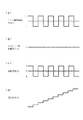
本発明の装置を検証する実験として、発振回路13からの周波数信号の周波数fcを1MHzとし、基準クロック信号の周波数fsを12MHzとして、実際にコンピュータによりデータ処理を行った。発振回路13からの周波数信号として使用した試験用の高周波信号(正弦波信号)は、周波数を僅かに1MHzから変化させておいた。図17は、試験用の高周波信号を基準クロック信号によりサンプリングしてディジタル値を求める様子を示す図である。こうして求められたディジタル値で特定される信号について周波数スペクトルを調べたところ図18に示すとおりであった。従ってここでは1MHzの正弦波信号を基本波とする高周波信号がA/D変換部21から取り出されることになる。
As an experiment for verifying the apparatus of the present invention, data processing was actually performed by a computer with the frequency fc of the frequency signal from the oscillation circuit 13 set to 1 MHz and the frequency fs of the reference clock signal set to 12 MHz. The test high frequency signal (sinusoidal signal) used as the frequency signal from the oscillation circuit 13 had a frequency slightly changed from 1 MHz. FIG. 17 is a diagram showing how a digital value is obtained by sampling a test high-frequency signal with a reference clock signal. When the frequency spectrum of the signal specified by the digital value thus obtained was examined, it was as shown in FIG. Therefore, a high-frequency signal having a 1 MHz sine wave signal as a fundamental wave is extracted from the A /
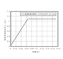
図19は、キャリアリムーブ31から出力されるI値及びQ値を示し、図20はローパスフィルタ32から得られるI値及びQ値を示している。この例では試験用の高周波信号について周波数を変化させているので、ローパスフィルタ32の出力値は上昇している。また図21は、この実施例においてオフセット周波数(周波数変化量)と検出出力との関係を示したものであり、オフセット周波数が大きくなると誤差が大きくなるが、オフセット周波数が小さい領域では、極めて両者の対応関係が良好であり、高い信頼性で周波数変化量を検出できることが理解される。また図22は、前記試験用の高周波信号の周波数を変化させた直後の時間的平均化処理部7の出力を示すものであり、0.1秒以内で周波数の変化量を検出できることが理解される。また周波数検出精度は、出力の上昇が止まって時間軸に平行になった領域の脈動の振幅に相当するが、この値は0.0035Hzであり、周波数検出精度が極めて高いことが裏付けされている。
FIG. 19 shows the I value and Q value output from the carrier remove 31, and FIG. 20 shows the I value and Q value obtained from the
1 センサ部
11 センサ用振動子である水晶振動子
13 発振回路
2 基準クロック発生部
31 キャリアリムーブ
32 ローパスフィルタ
4 減数処理部
5 補正処理部
6 速度演算部
7 時間平均化処理部
8 周波数レンジ補正部
9 逆回転ベクトル発生部
90 I/Qテーブル
100 ビット分割部
101 パルス幅制御部
103 アドレス制御部
DESCRIPTION OF
Claims (7)
周波数信号をサンプリングするためのクロック信号を発生させる基準クロック発生部と、
前記周波数信号を前記基準クロック発生部からのクロック信号によりサンプリングしてそのサンプリング値をディジタル信号として出力するアナログ/ディジタル変換部と、
このアナログ/ディジタル変換部からの出力信号に対応する周波数信号に対してディジタル信号による直交検波を行い、当該周波数信号における周波数と直交検波に用いたディジタル信号により特定される周波数との周波数差に相当する角速度で回転する回転ベクトルを複素表示したときの実数部分及び虚数部分を取り出す回転ベクトル取り出し手段と、
この回転ベクトル取り出し手段で得られた前記実数部分及び虚数部分の各時系列データに基づいて、回転ベクトルの角速度を求める回転ベクトル速度演算手段と、を備えたことを特徴とする周波数測定装置。 In a frequency measurement device that measures the frequency of a frequency signal,
A reference clock generator for generating a clock signal for sampling the frequency signal;
An analog / digital converter that samples the frequency signal with a clock signal from the reference clock generator and outputs the sampled value as a digital signal;
Corresponds to the frequency difference between the frequency of the frequency signal corresponding to the output signal from the analog / digital converter and the frequency specified by the digital signal used for the quadrature detection. Rotation vector extracting means for extracting a real part and an imaginary part when a rotation vector rotating at an angular velocity is displayed in a complex manner;
A frequency measurement apparatus comprising: a rotation vector speed calculation means for obtaining an angular speed of a rotation vector based on each time series data of the real part and the imaginary part obtained by the rotation vector extraction means.
この積分手段の出力値に対応する角速度でかつ前記回転ベクトル取り出し手段により取り出された回転ベクトルとは逆向きに回転する逆回転ベクトルを複素表示したときの実数部分及び虚数部分を作成する逆回転ベクトル生成部と、
前記回転ベクトル速度演算手段の前段に設けられ、前記回転ベクトル取り出し手段により得られた回転ベクトルと前記逆回転ベクトル生成部により生成された逆回転ベクトルとを乗算する手段と、を備えたことを特徴とする請求項1ないし4のいずれか一つに記載の周波数測定装置。 Integrating means for integrating the angular velocity obtained by the rotation vector speed calculating means;
A reverse rotation vector for creating a real part and an imaginary part when an angular velocity corresponding to the output value of the integration means and a reverse rotation vector rotating in the opposite direction to the rotation vector extracted by the rotation vector extraction means are displayed in a complex manner. A generator,
Provided in a preceding stage of the rotation vector speed calculation means, and means for multiplying the rotation vector obtained by the rotation vector extraction means and the reverse rotation vector generated by the reverse rotation vector generation unit. The frequency measurement device according to any one of claims 1 to 4.
前記アドレス生成部は、この加算部からの出力値を積分し、この積分値を前記データテーブルのアドレスとすることを特徴とする請求項6記載の周波数測定装置。 The reverse rotation vector generation unit outputs a pulse train having a duty ratio according to a value of a lower bit when the change amount of the frequency obtained by the rotation vector speed calculation unit is represented by a digital signal, and An addition unit that adds the value of the upper bits when the frequency change amount is represented by a digital signal and the level of the pulse created by the pulse width control unit and outputs the sum to the address control unit, and
7. The frequency measuring apparatus according to claim 6, wherein the address generation unit integrates an output value from the addition unit, and uses the integration value as an address of the data table.
Priority Applications (1)
| Application Number | Priority Date | Filing Date | Title |
|---|---|---|---|
| JP2008176520A JP2008249729A (en) | 2004-08-11 | 2008-07-07 | Device for measuring frequency |
Applications Claiming Priority (3)
| Application Number | Priority Date | Filing Date | Title |
|---|---|---|---|
| JP2004234735 | 2004-08-11 | ||
| JP2005038205 | 2005-02-15 | ||
| JP2008176520A JP2008249729A (en) | 2004-08-11 | 2008-07-07 | Device for measuring frequency |
Related Parent Applications (1)
| Application Number | Title | Priority Date | Filing Date |
|---|---|---|---|
| JP2005233149A Division JP4177361B2 (en) | 2004-08-11 | 2005-08-11 | Sensing device |
Publications (2)
| Publication Number | Publication Date |
|---|---|
| JP2008249729A true JP2008249729A (en) | 2008-10-16 |
| JP2008249729A5 JP2008249729A5 (en) | 2009-10-01 |
Family
ID=35839466
Family Applications (1)
| Application Number | Title | Priority Date | Filing Date |
|---|---|---|---|
| JP2008176520A Pending JP2008249729A (en) | 2004-08-11 | 2008-07-07 | Device for measuring frequency |
Country Status (4)
| Country | Link |
|---|---|
| US (2) | US7398163B2 (en) |
| EP (1) | EP1788377B1 (en) |
| JP (1) | JP2008249729A (en) |
| WO (1) | WO2006016721A1 (en) |
Cited By (2)
| Publication number | Priority date | Publication date | Assignee | Title |
|---|---|---|---|---|
| JP2014009979A (en) * | 2012-06-28 | 2014-01-20 | Nippon Dempa Kogyo Co Ltd | Frequency measurement device |
| JP2017502269A (en) * | 2013-12-02 | 2017-01-19 | コミッサリア ア レネルジ アトミック エ オー エネルジス アルテルナティヴスCommissariat A L‘Energie Atomique Et Aux Energies Alternatives | System and method for analyzing gas |
Families Citing this family (9)
| Publication number | Priority date | Publication date | Assignee | Title |
|---|---|---|---|---|
| JP4713459B2 (en) * | 2006-12-25 | 2011-06-29 | 日本電波工業株式会社 | Sensing device |
| US9214945B2 (en) * | 2012-02-27 | 2015-12-15 | Realtek Semiconductor Corp. | Digital phase lock loop and method thereof |
| US10599988B2 (en) | 2016-03-02 | 2020-03-24 | D-Wave Systems Inc. | Systems and methods for analog processing of problem graphs having arbitrary size and/or connectivity |
| US10859471B2 (en) * | 2016-10-03 | 2020-12-08 | Epro Gmbh | Synchronization of machine vibration data after collection |
| US11481354B2 (en) | 2018-04-24 | 2022-10-25 | D-Wave Systems Inc. | Systems and methods for calculating the ground state of non-diagonal Hamiltonians |
| US11593174B2 (en) | 2018-10-16 | 2023-02-28 | D-Wave Systems Inc. | Systems and methods for scheduling programs for dedicated execution on a quantum processor |
| WO2020150156A1 (en) | 2019-01-17 | 2020-07-23 | D-Wave Systems, Inc. | Systems and methods for hybrid algorithms using cluster contraction |
| US11593695B2 (en) | 2019-03-26 | 2023-02-28 | D-Wave Systems Inc. | Systems and methods for hybrid analog and digital processing of a computational problem using mean fields |
| US11714730B2 (en) | 2019-08-20 | 2023-08-01 | D-Wave Systems Inc. | Systems and methods for high availability, failover and load balancing of heterogeneous resources |
Family Cites Families (24)
| Publication number | Priority date | Publication date | Assignee | Title |
|---|---|---|---|---|
| US4090145A (en) * | 1969-03-24 | 1978-05-16 | Webb Joseph A | Digital quadrature demodulator |
| US4100512A (en) * | 1976-08-11 | 1978-07-11 | Office National D'etudes Et De Recherches Aerospatiales | Crystal oscillator compensated against frequency shift due to acceleration |
| US4318063A (en) * | 1979-05-03 | 1982-03-02 | The United States Of America As Represented By The Secretary Of The Air Force | Crystal oscillator compensated for g-sensitivity |
| US4453141A (en) * | 1982-01-28 | 1984-06-05 | The United States Of America As Represented By The Secretary Of The Army | Suppression of vibration effects on piezoelectric crystal resonators |
| FR2554992A1 (en) * | 1983-11-15 | 1985-05-17 | Cepe | DEVICE FOR COMPENSATING THE SENSITIVITY TO ACCELERATION OF AN OSCILLATOR |
| US4588969A (en) * | 1984-08-17 | 1986-05-13 | Frequency And Time Systems, Inc. | Adjustable crystal oscillator with acceleration compensation |
| CA1227357A (en) * | 1985-02-12 | 1987-09-29 | Minister Of National Defence | Method and apparatus for detecting presence and concentration of vapours in gaseous fluids |
| JPS62502439A (en) * | 1985-04-04 | 1987-09-17 | モトロ−ラ・インコ−ポレ−テッド | Digital zero IF selection stage |
| US4750214A (en) * | 1986-06-11 | 1988-06-07 | Rockwell International Corporation | Digital FM demodulator using delayed signal product with arctangent |
| DE3629588A1 (en) * | 1986-08-30 | 1988-03-03 | Franz Dipl Ing Leitl | CRYSTAL OSCILLATOR COMPENSATION CIRCUIT |
| US4891611A (en) * | 1989-03-09 | 1990-01-02 | Rockwell International Corporation | Vibration compensated crystal oscillator |
| JPH03140838A (en) * | 1989-10-26 | 1991-06-14 | Brother Ind Ltd | Gas sensor |
| JP2675733B2 (en) | 1993-02-17 | 1997-11-12 | 日本電信電話株式会社 | Chemical sensing equipment |
| JP3139656B2 (en) | 1993-04-20 | 2001-03-05 | 横河電機株式会社 | Signal conversion circuit |
| JP2666709B2 (en) * | 1993-12-24 | 1997-10-22 | 日本電気株式会社 | Oscillator |
| US6033852A (en) * | 1996-09-27 | 2000-03-07 | University Of Maine | Monolithic piezoelectric sensor (MPS) for sensing chemical, biochemical and physical measurands |
| US5786735A (en) * | 1997-02-27 | 1998-07-28 | The United States Of America As Represented By The Secretary Of The Army | Phase and magnitude compensated tuning for suppression of vibration induced phase noise of crystal oscillator with varying vibration frequencies |
| JP2001000435A (en) | 1999-06-16 | 2001-01-09 | Toshiba Corp | Apparatus for ultrasonography |
| US7098748B2 (en) * | 2001-09-21 | 2006-08-29 | Schmidt Dominik J | Integrated CMOS high precision piezo-electrically driven clock |
| US6707346B2 (en) * | 2001-12-19 | 2004-03-16 | The Boeing Company | Apparatus and method for improved crystal time reference |
| JP3729181B2 (en) * | 2003-03-14 | 2005-12-21 | セイコーエプソン株式会社 | Measuring method, measuring signal output circuit and measuring apparatus |
| US7106143B2 (en) * | 2004-03-31 | 2006-09-12 | Frequency Electronics, Inc. | Method for achieving highly reproducible acceleration insensitive quartz crystal oscillators |
| WO2006038367A1 (en) * | 2004-10-04 | 2006-04-13 | Niigata University | Substance adsorption detecting method and sensor |
| JP4128191B2 (en) * | 2005-05-19 | 2008-07-30 | 国立大学法人名古屋大学 | Digital data recording apparatus, sampling data specifying method thereof, and sampling data specifying program |
-
2005
- 2005-08-11 WO PCT/JP2005/015099 patent/WO2006016721A1/en active Application Filing
- 2005-08-11 US US11/659,764 patent/US7398163B2/en active Active
- 2005-08-11 EP EP05772559.0A patent/EP1788377B1/en active Active
-
2008
- 2008-05-28 US US12/154,941 patent/US7899633B2/en active Active
- 2008-07-07 JP JP2008176520A patent/JP2008249729A/en active Pending
Cited By (2)
| Publication number | Priority date | Publication date | Assignee | Title |
|---|---|---|---|---|
| JP2014009979A (en) * | 2012-06-28 | 2014-01-20 | Nippon Dempa Kogyo Co Ltd | Frequency measurement device |
| JP2017502269A (en) * | 2013-12-02 | 2017-01-19 | コミッサリア ア レネルジ アトミック エ オー エネルジス アルテルナティヴスCommissariat A L‘Energie Atomique Et Aux Energies Alternatives | System and method for analyzing gas |
Also Published As
| Publication number | Publication date |
|---|---|
| WO2006016721A1 (en) | 2006-02-16 |
| US7398163B2 (en) | 2008-07-08 |
| US20070251322A1 (en) | 2007-11-01 |
| EP1788377A1 (en) | 2007-05-23 |
| EP1788377B1 (en) | 2015-11-04 |
| EP1788377A4 (en) | 2014-04-02 |
| US7899633B2 (en) | 2011-03-01 |
| US20090055112A1 (en) | 2009-02-26 |
Similar Documents
| Publication | Publication Date | Title |
|---|---|---|
| JP2008249729A (en) | Device for measuring frequency | |
| JP4177361B2 (en) | Sensing device | |
| US7054778B2 (en) | Method and device for processing analogue output signals from capacitive sensors | |
| JP4611959B2 (en) | Sensing method | |
| EP1832862A1 (en) | Sensing apparatus | |
| US20040085096A1 (en) | Efficient digital method of and system for determining the instantaneous phase and amplitude of a vibratory accelerometer and other sensors | |
| CN107209028A (en) | Analyser device | |
| CN101014848B (en) | Sensing apparatus | |
| JP2006258787A5 (en) | ||
| CN1885043A (en) | Digital control circuit and method for small phase-lock amplifier | |
| JP4594162B2 (en) | Sensing device | |
| US6789029B2 (en) | Method and apparatus for signal extraction in an electronic sensor | |
| JP6809695B2 (en) | Asynchronous FRA | |
| JP6995403B2 (en) | Asynchronous FRA and synchronous detector | |
| JP3252641B2 (en) | Phase difference measuring device | |
| JP2007170891A (en) | Arithmetic unit and testing apparatus | |
| JP2006029874A (en) | Sensor | |
| Singh et al. | Doppler velocity measurement using closed-loop Goertzel algorithm in PLL technique | |
| US20080046201A1 (en) | Coriolis Flowmeter | |
| JPH02291968A (en) | Resolver speed detecting circuit | |
| JPH109946A (en) | Device for analyzing periodic motion of rotary device | |
| JPH109947A (en) | Device for analyzing periodic motion | |
| JPH06147949A (en) | Mass flowmeter | |
| JPH11214931A (en) | Fm detection system | |
| JP2006352390A (en) | Digital filter |
Legal Events
| Date | Code | Title | Description |
|---|---|---|---|
| A621 | Written request for application examination |
Free format text: JAPANESE INTERMEDIATE CODE: A621 Effective date: 20080707 |
|
| A521 | Written amendment |
Free format text: JAPANESE INTERMEDIATE CODE: A523 Effective date: 20090819 |
|
| A871 | Explanation of circumstances concerning accelerated examination |
Free format text: JAPANESE INTERMEDIATE CODE: A871 Effective date: 20090819 |
|
| A975 | Report on accelerated examination |
Free format text: JAPANESE INTERMEDIATE CODE: A971005 Effective date: 20090904 |
|
| A131 | Notification of reasons for refusal |
Free format text: JAPANESE INTERMEDIATE CODE: A131 Effective date: 20090915 |
|
| A521 | Written amendment |
Free format text: JAPANESE INTERMEDIATE CODE: A523 Effective date: 20091116 |
|
| A02 | Decision of refusal |
Free format text: JAPANESE INTERMEDIATE CODE: A02 Effective date: 20091215 |