JP2008230214A - Sealing structure and sealing method of fluid lead-out part, fluid container, refilling fluid container, and its refilling method - Google Patents
Sealing structure and sealing method of fluid lead-out part, fluid container, refilling fluid container, and its refilling method Download PDFInfo
- Publication number
- JP2008230214A JP2008230214A JP2007132728A JP2007132728A JP2008230214A JP 2008230214 A JP2008230214 A JP 2008230214A JP 2007132728 A JP2007132728 A JP 2007132728A JP 2007132728 A JP2007132728 A JP 2007132728A JP 2008230214 A JP2008230214 A JP 2008230214A
- Authority
- JP
- Japan
- Prior art keywords
- fluid
- ink
- sealing film
- seal member
- sealing
- Prior art date
- Legal status (The legal status is an assumption and is not a legal conclusion. Google has not performed a legal analysis and makes no representation as to the accuracy of the status listed.)
- Pending
Links
Images


Classifications
-
- B—PERFORMING OPERATIONS; TRANSPORTING
- B41—PRINTING; LINING MACHINES; TYPEWRITERS; STAMPS
- B41J—TYPEWRITERS; SELECTIVE PRINTING MECHANISMS, i.e. MECHANISMS PRINTING OTHERWISE THAN FROM A FORME; CORRECTION OF TYPOGRAPHICAL ERRORS
- B41J29/00—Details of, or accessories for, typewriters or selective printing mechanisms not otherwise provided for
-
- B—PERFORMING OPERATIONS; TRANSPORTING
- B41—PRINTING; LINING MACHINES; TYPEWRITERS; STAMPS
- B41J—TYPEWRITERS; SELECTIVE PRINTING MECHANISMS, i.e. MECHANISMS PRINTING OTHERWISE THAN FROM A FORME; CORRECTION OF TYPOGRAPHICAL ERRORS
- B41J2/00—Typewriters or selective printing mechanisms characterised by the printing or marking process for which they are designed
- B41J2/005—Typewriters or selective printing mechanisms characterised by the printing or marking process for which they are designed characterised by bringing liquid or particles selectively into contact with a printing material
- B41J2/01—Ink jet
- B41J2/17—Ink jet characterised by ink handling
- B41J2/175—Ink supply systems ; Circuit parts therefor
- B41J2/17503—Ink cartridges
- B41J2/17506—Refilling of the cartridge
- B41J2/17509—Whilst mounted in the printer
-
- B—PERFORMING OPERATIONS; TRANSPORTING
- B41—PRINTING; LINING MACHINES; TYPEWRITERS; STAMPS
- B41J—TYPEWRITERS; SELECTIVE PRINTING MECHANISMS, i.e. MECHANISMS PRINTING OTHERWISE THAN FROM A FORME; CORRECTION OF TYPOGRAPHICAL ERRORS
- B41J2/00—Typewriters or selective printing mechanisms characterised by the printing or marking process for which they are designed
- B41J2/005—Typewriters or selective printing mechanisms characterised by the printing or marking process for which they are designed characterised by bringing liquid or particles selectively into contact with a printing material
- B41J2/01—Ink jet
- B41J2/17—Ink jet characterised by ink handling
- B41J2/175—Ink supply systems ; Circuit parts therefor
- B41J2/17503—Ink cartridges
- B41J2/17513—Inner structure
-
- B—PERFORMING OPERATIONS; TRANSPORTING
- B41—PRINTING; LINING MACHINES; TYPEWRITERS; STAMPS
- B41J—TYPEWRITERS; SELECTIVE PRINTING MECHANISMS, i.e. MECHANISMS PRINTING OTHERWISE THAN FROM A FORME; CORRECTION OF TYPOGRAPHICAL ERRORS
- B41J2/00—Typewriters or selective printing mechanisms characterised by the printing or marking process for which they are designed
- B41J2/005—Typewriters or selective printing mechanisms characterised by the printing or marking process for which they are designed characterised by bringing liquid or particles selectively into contact with a printing material
- B41J2/01—Ink jet
- B41J2/17—Ink jet characterised by ink handling
- B41J2/175—Ink supply systems ; Circuit parts therefor
- B41J2/17503—Ink cartridges
- B41J2/1752—Mounting within the printer
-
- B—PERFORMING OPERATIONS; TRANSPORTING
- B41—PRINTING; LINING MACHINES; TYPEWRITERS; STAMPS
- B41J—TYPEWRITERS; SELECTIVE PRINTING MECHANISMS, i.e. MECHANISMS PRINTING OTHERWISE THAN FROM A FORME; CORRECTION OF TYPOGRAPHICAL ERRORS
- B41J2/00—Typewriters or selective printing mechanisms characterised by the printing or marking process for which they are designed
- B41J2/005—Typewriters or selective printing mechanisms characterised by the printing or marking process for which they are designed characterised by bringing liquid or particles selectively into contact with a printing material
- B41J2/01—Ink jet
- B41J2/17—Ink jet characterised by ink handling
- B41J2/175—Ink supply systems ; Circuit parts therefor
- B41J2/17503—Ink cartridges
- B41J2/17553—Outer structure
-
- B—PERFORMING OPERATIONS; TRANSPORTING
- B41—PRINTING; LINING MACHINES; TYPEWRITERS; STAMPS
- B41J—TYPEWRITERS; SELECTIVE PRINTING MECHANISMS, i.e. MECHANISMS PRINTING OTHERWISE THAN FROM A FORME; CORRECTION OF TYPOGRAPHICAL ERRORS
- B41J2/00—Typewriters or selective printing mechanisms characterised by the printing or marking process for which they are designed
- B41J2/005—Typewriters or selective printing mechanisms characterised by the printing or marking process for which they are designed characterised by bringing liquid or particles selectively into contact with a printing material
- B41J2/01—Ink jet
- B41J2/17—Ink jet characterised by ink handling
- B41J2/175—Ink supply systems ; Circuit parts therefor
- B41J2/17596—Ink pumps, ink valves
-
- Y—GENERAL TAGGING OF NEW TECHNOLOGICAL DEVELOPMENTS; GENERAL TAGGING OF CROSS-SECTIONAL TECHNOLOGIES SPANNING OVER SEVERAL SECTIONS OF THE IPC; TECHNICAL SUBJECTS COVERED BY FORMER USPC CROSS-REFERENCE ART COLLECTIONS [XRACs] AND DIGESTS
- Y10—TECHNICAL SUBJECTS COVERED BY FORMER USPC
- Y10T—TECHNICAL SUBJECTS COVERED BY FORMER US CLASSIFICATION
- Y10T29/00—Metal working
- Y10T29/49—Method of mechanical manufacture
- Y10T29/49401—Fluid pattern dispersing device making, e.g., ink jet
Abstract
Description
本発明は、例えばプリンタ用のインクカートリッジ等に好適な流体導出部のシール構造体及びシール方法並びに流体収容容器、再充填流体収容容器及びその再充填方法に関する。 The present invention relates to a seal structure and seal method for a fluid outlet suitable for an ink cartridge for a printer, for example, a fluid container, a refill fluid container, and a refill method thereof.
従来、液体噴射ヘッドのノズルから液滴を噴射する液体噴射装置として、インクジェット式プリンタがある。このインクジェット式プリンタには、インクカートリッジをキャリッジ以外の場所に搭載するオフキャリッジタイプのインク供給システムを備えるものがある。このオフキャリッジタイプのインク供給システムを備える場合としては、大判印刷のために大容量のインクカートリッジを備える場合、及び、インクカートリッジを搭載しないことによりキャリッジを小型化し、インクジェット式プリンタを小型化、薄型化する場合等がある。 2. Description of the Related Art Conventionally, there is an ink jet printer as a liquid ejecting apparatus that ejects liquid droplets from a nozzle of a liquid ejecting head. Some ink jet printers include an off-carriage type ink supply system in which an ink cartridge is mounted at a place other than a carriage. The off-carriage type ink supply system includes a large-capacity ink cartridge for large-format printing, and the carriage is downsized by not mounting the ink cartridge, and the inkjet printer is downsized and thin. There are some cases.
このオフキャリッジタイプのインク供給システムでは、例えば、インクカートリッジを本体側に配設する。そして、インクカートリッジから、インク供給チューブを介して、キャリッジに搭載されたサブタンク等へインクを供給する。一方、プリンタの印刷の高速化、高精細化によるインクの流量の増加のため、インク供給チューブ内のインクの動圧が高まり、サブタンクへのインクの供給量が不足する問題があった。 In this off-carriage type ink supply system, for example, an ink cartridge is disposed on the main body side. Then, ink is supplied from the ink cartridge to a sub tank or the like mounted on the carriage via an ink supply tube. On the other hand, there has been a problem that the dynamic pressure of the ink in the ink supply tube is increased due to the increase in the ink flow rate due to the higher speed and higher definition of printing by the printer, and the amount of ink supplied to the sub tank is insufficient.
この問題に対し、インクカートリッジのケース内に袋状のインクパックを収容し、ケースとインクパックとの間に空気を導入することにより、インクパックを加圧して強制的にインクを導出するインクカートリッジがあった(特許文献1)。 In order to solve this problem, an ink cartridge that forcibly draws out ink by pressurizing the ink pack by storing a bag-shaped ink pack in the case of the ink cartridge and introducing air between the case and the ink pack (Patent Document 1).
また、インクパックには弁機構を備えたインク導出部が連結され、このインク導出部をケースより露出させるために、ケースには開口が設けられている。そして、インク導出部の端面と、開口の周囲のケースとを、封止フィルムにより熱溶着することで、ケースの開口をシールすることが行なわれている(特許文献2の図5)。 The ink pack is connected to an ink lead-out portion having a valve mechanism, and the case is provided with an opening in order to expose the ink lead-out portion from the case. Then, the opening of the case is sealed by thermally welding the end surface of the ink outlet portion and the case around the opening with a sealing film (FIG. 5 of Patent Document 2).
ここで、インク導出部にはインク通路が設けられ、このインク通路には、インク通路の内壁に密着する弾性リングで形成されたシール部材と、シール部材と当接可能に配置された可動の弁体と、この弁体をシール部材に圧接するように付勢するコイルスプリングが配置される。さらに、インク通路は、封止フィルムを破ってインク導出針を受け入れ可能である。シール部材は、インク導出針が挿通される以前では、弁体がコイルスプリングにより圧接されることでインク通路を遮断する弁座部材としても機能する。インク導出針が封止フィルムを破ってインク流体通路に挿入された時には、インク導出針によりコイルスプリングの付勢力に抗して弁体がシール部材より離間されて、インク通路が開放される。 Here, an ink passage is provided in the ink lead-out portion, and in this ink passage, a seal member formed by an elastic ring in close contact with the inner wall of the ink passage, and a movable valve disposed so as to be able to contact the seal member A body and a coil spring that urges the valve body to press against the seal member are disposed. Further, the ink passage can break the sealing film and accept the ink lead-out needle. Before the ink lead-out needle is inserted, the seal member also functions as a valve seat member that blocks the ink passage when the valve body is pressed by a coil spring. When the ink lead-out needle breaks the sealing film and is inserted into the ink fluid passage, the ink lead-off needle separates the valve body from the seal member against the biasing force of the coil spring, and the ink passage is opened.
インク通路が開放された時には、インクはインク導出針に形成されたインク流路のみから導出されなければならない。このため、シール部材が弾性リングにて形成され、インク導出針とシール部材との間と、シール部材とインク通路内壁との間を弾性的にシールしていた。 When the ink passage is opened, the ink must be led out only from the ink flow path formed in the ink lead needle. For this reason, the seal member is formed of an elastic ring, and elastically seals between the ink lead-out needle and the seal member and between the seal member and the ink passage inner wall.
しかし、例えばインク導出部のインク通路の真円度の精度が悪化していると、シール部材とインク通路内壁との間を弾性シールが不完全となり、インク漏れが生ずる。また、特許文献1に記載のようにインクを加圧して供給する場合には、シール部材とインク通路内壁との間を弾性シール性が弱いと、圧送されるインクによってシールが破られる虞もある。さらには、インクカートリッジの落下や、インクカートリッジに振動が加わった場合にも、シール部材とインク通路内壁との間を弾性シールが一時的に破られる虞がある。
However, for example, when the accuracy of the roundness of the ink passage of the ink outlet portion is deteriorated, the elastic seal is incomplete between the seal member and the inner wall of the ink passage, and ink leakage occurs. Further, when ink is pressurized and supplied as described in
この種の問題は、インクカートリッジに限らず、流体導出部に形成された流体通路の内壁とシール部材とで弾性シールするタイプの各種の用途においても同様に生じえるものである。例えば、プリンタであれば、オフキャリッジやオンキャリッジに限らず、インク流路の接続部にはこの種のインク導出部が各所に配置される。プリンタに限らず、液体燃料カートリッジの液体燃料導出部(特許文献3の図5)や、液体以外の気体流路の接続部にも同様の構造が採用され得る。
そこで、本発明の目的は、流体導出部に形成された流体通路の内壁とシール部材との間の弾性シールに頼らずに、流体通路の内壁とシール部材との間からの流体漏れを確実に防止することができる流体導出部のシール構造体及びシール方法並びに流体収容容器、再充填流体収容容器及びその再充填方法を提供することにある。 Therefore, an object of the present invention is to reliably prevent fluid leakage from between the inner wall of the fluid passage and the seal member without relying on an elastic seal between the inner wall of the fluid passage formed in the fluid outlet portion and the seal member. It is an object of the present invention to provide a seal structure and a sealing method for a fluid outlet portion that can be prevented, a fluid container, a refill fluid container, and a refill method thereof.
本発明の一態様に係る流体導出部のシール構造体は、流体通路と、前記流体通路の流体導出端に形成された開口端面とを含む流体導出部と、
前記流体導出部の前記流体通路内に配置されるシール部材と、
前記流体導出部の前記流体通路及び前記開口端面を覆って配置され、前記開口端面及び前記シール部材に熱溶着される封止フィルムと、
を有することを特徴とする。
A seal structure for a fluid outlet according to an aspect of the present invention includes a fluid outlet including a fluid passage and an opening end surface formed at a fluid outlet of the fluid passage;
A seal member disposed in the fluid passage of the fluid outlet;
A sealing film disposed over the fluid passage and the opening end surface of the fluid outlet and thermally welded to the opening end surface and the seal member;
It is characterized by having.
本発明の一態様によれば、熱溶着された封止フィルムにより、流体通路の内壁とシール部材の外壁との間の空隙がシールされるので、流体通路の真円度の精度が悪くシール部材と流体通路内壁とのシール性に依存しなくて済む。また、流体導出部の落下や振動により一時的に、シール部材と流体通路内壁とのシール性が損なわれても、熱溶着された封止フィルムにより流体漏れを確実に防止できる。 According to one aspect of the present invention, since the gap between the inner wall of the fluid passage and the outer wall of the seal member is sealed by the heat-sealed sealing film, the accuracy of the roundness of the fluid passage is poor and the seal member There is no need to depend on the sealability between the fluid passage and the inner wall of the fluid passage. Moreover, even if the sealing performance between the sealing member and the fluid passage inner wall is temporarily impaired due to the drop or vibration of the fluid lead-out portion, fluid leakage can be reliably prevented by the heat-sealed sealing film.
本発明の一態様では、前記流体通路は、前記封止フィルムを破って流体導出針を受け入れ可能であり、前記シール部材は、前記流体導出針が密着して挿通される孔部を有する弾性リングにて形成することができる。この場合、弾性リングで形成されたシール部材は、流体導出針の外壁との間で締りばめによるシール性を発揮するだけでよい。 In one aspect of the present invention, the fluid passage can break the sealing film and receive the fluid outlet needle, and the sealing member has an elastic ring having a hole through which the fluid outlet needle is closely inserted. Can be formed. In this case, the sealing member formed of an elastic ring only needs to exhibit a sealing property by interference fit with the outer wall of the fluid outlet needle.
本発明の一態様では、前記流体通路内にて、前記シール部材と当接可能に配置された可動の弁体と、前記弁体を前記シール部材に圧接するように付勢する付勢部材とをさらに有することができる。こうすると、前記シール部材は、前記流体導出針が挿通される以前は、前記弁体が圧接されて前記流体通路を遮断する弁座部材として機能し、前記流体導出針が前記封止フィルムを破って前記流体通路に挿入された時に、前記流体導出針により前記付勢部材の付勢力に抗して前記弁体が前記シール部材より離間されて、前記流体通路を開放することができる。 In one aspect of the present invention, a movable valve body disposed so as to be able to contact the seal member in the fluid passage, and a biasing member that biases the valve body so as to press-contact the seal member. Can further be included. Then, before the fluid lead-out needle is inserted, the seal member functions as a valve seat member that presses the valve body and blocks the fluid passage, and the fluid lead-out needle breaks the sealing film. When inserted into the fluid passage, the valve body is separated from the seal member against the biasing force of the biasing member by the fluid outlet needle, and the fluid passage can be opened.
本発明の一態様では、前記開口端面は環状に突出した第1溶着代を含み、前記シール部材は環状に突出した第2溶着代を含み、前記第1溶着代及び前記第2溶着代を、前記封止フィルムと熱溶着することができる。こうすると、熱溶着領域を限定できるので、熱溶着の圧力と溶着時間を少なくできる。しかも溶着代の有無で溶着終了時期を判断でき、溶着の均質化が図れる。 In one aspect of the present invention, the opening end surface includes a first welding allowance protruding in an annular shape, the seal member includes a second welding allowance protruding in an annular shape, the first welding allowance and the second welding allowance, It can be heat-welded with the sealing film. In this way, the heat welding region can be limited, so that the heat welding pressure and welding time can be reduced. Moreover, the welding end time can be determined by the presence or absence of the welding allowance, and the welding can be homogenized.
本発明の一態様では、前記シール部材は、前記シール部材の外面と、前記流体通路の内壁面とが当接することによって位置決めすることができる。 In one aspect of the present invention, the seal member can be positioned by contacting an outer surface of the seal member and an inner wall surface of the fluid passage.
つまり、シール部材と流体通路との間のシールは不要であり、位置決めできる関係が維持されればよい。シール部材の位置決めを行なうと、溶着時のシール部材の位置が部品間で均一化され、製品不良を低減できる。 In other words, the seal between the seal member and the fluid passage is not necessary, and it is only necessary to maintain a positioning relationship. When the seal member is positioned, the position of the seal member at the time of welding is made uniform among components, and product defects can be reduced.
本発明の一態様では、前記流体導出部、前記シール部材及び前記封止フィルムは、ポリオレフィン系材料を含むことができる。ポリオレフィン系材料は、流体例えばインクと接触する材料として信頼性が高く、材質の共通化により熱溶着が担保される。 In one aspect of the present invention, the fluid outlet portion, the seal member, and the sealing film may include a polyolefin-based material. Polyolefin-based materials are highly reliable as materials that come into contact with fluids such as ink, and heat welding is ensured by the common use of materials.
本発明の一態様では、前記ポリオレフィン系材料を、流体特にインクに接触する材料として特に信頼性が高いポリプロピレンまたはポリエチレンとすることができる。これらの材料に対して、良好に熱溶着可能なシール材を見出したことが、本発明の発端となっている。 In one aspect of the present invention, the polyolefin-based material may be polypropylene or polyethylene that is particularly reliable as a material that contacts a fluid, particularly ink. The discovery of a sealing material that can be satisfactorily thermally welded to these materials is the origin of the present invention.
本発明の一態様では、前記封止フィルムは異種材料から形成された複数層にて形成され、前記流体導出部及び前記シール部材と面する側の最端層を、前記ポリオレフィン系材料にて形成することができる。こうすると、熱溶着性を担保しながら、熱溶着層とは異なる材質の特性を併せ持たせることができる。例えば、前記最端層と隣接する層は、前記ポリオレフィン系材料よりも溶融点が高い材料にて形成することができ、これにより封止フィルムの保形性を熱溶着後でも維持できる。この種の材質として、ポリエチレンテレフタレートまたはポリアミドをあげることができる。 In one aspect of the present invention, the sealing film is formed of a plurality of layers formed of different materials, and the outermost layer facing the fluid outlet and the seal member is formed of the polyolefin-based material. can do. If it carries out like this, while ensuring heat-weldability, it can have the characteristic of the material different from a heat-welding layer. For example, the layer adjacent to the outermost layer can be formed of a material having a melting point higher than that of the polyolefin-based material, whereby the shape retention of the sealing film can be maintained even after heat welding. Examples of this type of material include polyethylene terephthalate or polyamide.
本発明の一態様では、前記封止フィルムは、前記ポリオレフィン系材料を含有する熱可塑性エラストマーとすることができる。上述したポリプロピレン、ポリエチレンと良好な熱溶着性を発揮できるからである。 In one aspect of the present invention, the sealing film may be a thermoplastic elastomer containing the polyolefin-based material. This is because good heat weldability can be exhibited with the above-described polypropylene and polyethylene.
本発明の他の態様に係る流体収容容器は、流体が収容された流体収容袋と、
前記流体収容袋に連結された上述のシール構造体と、
を有して構成することができる。
A fluid storage container according to another aspect of the present invention includes a fluid storage bag in which a fluid is stored,
The above-described seal structure coupled to the fluid containing bag;
Can be configured.
この場合、前記流体収容袋及びそれに連結される前記シール構造体を収容する空間が形成された筐体をさらに有し、前記筐体は、前記流体収容袋内の流体を圧送するための加圧流体が導入される加圧口と、前記シール構造体の前記開口端面を露出させる開口と、
を有し、前記封止フィルムを、前記開口の周囲の前記筐体にも熱溶着することができる。こうすると、加圧流体のシールも封止フィルムにて兼用できる。
In this case, it further has a housing in which a space for housing the fluid containing bag and the seal structure connected thereto is formed, and the housing is pressurized for pumping the fluid in the fluid containing bag. A pressure inlet into which a fluid is introduced, an opening exposing the opening end face of the seal structure, and
And the sealing film can be thermally welded to the casing around the opening. If it carries out like this, the sealing of a pressurized fluid can also be combined with a sealing film.
本発明のさらに他の態様に係る流体収容容器は、流体が収容された流体収容袋と、前記流体収容袋の流体導出口に連結された流体残量検出ユニットと、前記流体残量検出ユニットに連結された、上述の構造体を有して構成することができる。つまり、本発明のシール構造体は、流体収容容器に直接連結されるものに限らず、流体残量検出ユニットに連結されるものでもよい。 A fluid storage container according to still another aspect of the present invention includes a fluid storage bag in which a fluid is stored, a fluid remaining amount detection unit connected to a fluid outlet of the fluid storage bag, and the fluid remaining amount detection unit. It can be configured with the above-described structures connected. That is, the seal structure of the present invention is not limited to being directly connected to the fluid storage container but may be connected to the fluid remaining amount detection unit.
本発明のさらに他の態様は、上述の流体収容容器が、流体導出針により前記封止フィルムが突き破られて前記流体収容袋内の流体が導出された後に回収され、前記流体収容袋内に流体が再充填された再充填流体収容容器であって、
突き破られた前記封止フィルムは、前記開口端面及び前記シール部材との熱溶着が保持されており、
前記封止フィルムに重ねて接合され、前記封止フィルムの突き破られた領域を少なくとも被覆する被覆フィルムをさらに有することを特徴とする。
According to still another aspect of the present invention, the above-described fluid container is collected after the sealing film is pierced by the fluid outlet needle and the fluid in the fluid container bag is led out, and is collected in the fluid container bag. A refilled fluid container filled with fluid,
The sealed sealing film that has been breached is held in thermal contact with the opening end face and the sealing member,
It is characterized by further comprising a covering film which is overlapped and bonded to the sealing film and covers at least the pierced region of the sealing film.
こうすると、破断された封止フィルムのシール機能を再利用しながら、被覆フィルムを追加するだけで、回収された流体収容容器を再充填流体収容容器として再利用でき、かつ回収された流体収容容器の商品価値を担保することができる。 In this case, the recovered fluid storage container can be reused as a refilled fluid storage container simply by adding a covering film while reusing the sealing function of the broken sealing film, and the recovered fluid storage container The product value can be secured.
本発明のさらに他の態様に係る流体導出部のシール方法は、流体通路と、前記流体通路の流体導出端に形成された開口端面とを含む流体導出部に対して、前記開口端面側より、シール部材を挿入して、前記シール部材を前記開口端面と実質的に面一に配置する工程と、
前記前記流体導出部の前記流体通路及び前記開口端面を覆って封止フィルムを配置する工程と、
前記封止フィルムを、前記開口端面及び前記シール部材に熱溶着する工程と、
を有することを特徴とする。
According to still another aspect of the present invention, there is provided a fluid lead-out portion sealing method, wherein the fluid lead-out portion includes a fluid passage and an opening end face formed at a fluid lead-out end of the fluid passage. Inserting a seal member and placing the seal member substantially flush with the open end surface;
Disposing a sealing film so as to cover the fluid passage and the opening end surface of the fluid outlet portion;
Heat sealing the sealing film to the opening end face and the sealing member;
It is characterized by having.
シール部材を流体導出部材の開口端面と実質的に面一にすることで、溶着作業を確実にかつ簡便に実施することができる。 By making the seal member substantially flush with the opening end face of the fluid outlet member, the welding operation can be carried out reliably and simply.
ここで、前記シール部材の挿入工程では、前記シール部材の外面と、前記流体通路の内壁面とを当接させることによって、前記シール部材の位置決めを行なうことにより、前記開口端面と前記シール部材とを面一に設定することが好ましい。シール部材と流体導出部材の開口端面とを面一することが、機械的に保障されるからである。 Here, in the step of inserting the seal member, the opening end surface and the seal member are positioned by positioning the seal member by bringing the outer surface of the seal member into contact with the inner wall surface of the fluid passage. Is preferably set flush. This is because it is mechanically ensured that the sealing member and the opening end surface of the fluid outlet member are flush with each other.
さらに、前記シール部材の挿入工程では、前記シール部材に突出形成された環状の第2溶着代を、前記開口端面に突出形成された環状の第1溶着代の端面と実質的に面一に設定し、前記熱溶着工程では、前記第1及び第2溶着代を溶融させて、前記封止フィルムと熱溶着させることができる。上述の通り、熱溶着領域を限定できるので、熱溶着の圧力と溶着時間を少なくできる。しかも溶着代の有無で溶着終了時期を判断でき、溶着の均質化が図れる。 Furthermore, in the step of inserting the seal member, the annular second welding margin protrudingly formed on the seal member is set substantially flush with the end surface of the annular first welding margin protrudingly formed on the opening end surface. In the thermal welding step, the first and second welding margins can be melted and thermally welded to the sealing film. As described above, since the heat welding region can be limited, the heat welding pressure and welding time can be reduced. Moreover, the welding end time can be determined by the presence or absence of the welding allowance, and the welding can be homogenized.
本発明のさらに他の態様は、上述した流体収容容器が、流体導出針により前記封止フィルムが突き破られて前記流体収容袋内の流体が導出された後に回収され、前記流体収容袋内に流体を再充填する流体収容容器への再充填方法であって、
突き破られた前記封止フィルムと、前記開口端面及び前記シール部材との熱溶着により前記開口面側でのシールを保持しながら、前記流体収容袋内に流体を再充填する工程と、
再充填工程後に、前記封止フィルムの突き破られた領域を少なくとも被覆する被覆フィルムを、前記封止フィルムに重ねて接合する工程と、
を有することを特徴とする。
According to still another aspect of the present invention, the above-described fluid container is collected after the sealing film is pierced by the fluid outlet needle and the fluid in the fluid container bag is led out, and is contained in the fluid container bag. A method for refilling a fluid container that refills a fluid, comprising:
Refilling the fluid containing bag with fluid while holding the seal on the opening surface side by thermal welding of the sealed sealing film, the opening end surface and the seal member;
After the refilling step, a step of overlaying and bonding the covering film that covers at least the pierced region of the sealing film to the sealing film;
It is characterized by having.
これにより、破断された封止フィルムのシール機能を再利用しながら、被覆フィルムを追加するだけで、回収された流体収容容器を再充填流体収容容器として再利用でき、かつ回収された流体収容容器の商品価値を担保することができる。 Accordingly, the recovered fluid storage container can be reused as a refilled fluid storage container simply by adding a covering film while reusing the sealing function of the broken sealing film, and the recovered fluid storage container The product value can be secured.
(第1実施形態)
以下、本発明の好適な実施の形態について詳細に説明する。なお以下に説明する本実施形態は特許請求の範囲に記載された本発明の内容を不当に限定するものではなく、本実施形態で説明される構成の全てが本発明の解決手段として必須であるとは限らない。
(First embodiment)
Hereinafter, preferred embodiments of the present invention will be described in detail. The present embodiment described below does not unduly limit the contents of the present invention described in the claims, and all the configurations described in the present embodiment are indispensable as means for solving the present invention. Not necessarily.
(流体噴出装置の概要)
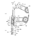
図1に示すように、本実施形態の流体噴射装置としてのプリンタ11は、フレーム12によって覆われている。そして、フレーム12内に、図2に示すように、ガイド軸14、キャリッジ15、液体噴射ヘッドとしての記録ヘッド20、バルブユニット21、液体収容体としてのインクカートリッジ23(図1参照)、加圧ポンプ25(図1参照)を備える。
(Outline of fluid ejection device)
As shown in FIG. 1, a
図1に示すように、フレーム12は、略直方体形状の箱体であり、その前面には、カートリッジホルダ12aが形成されている。
As shown in FIG. 1, the
図2に示すように、ガイド軸14は棒状に形成され、フレーム12内に架設されている。なお、本実施形態においては、ガイド軸14の架設されている方向を主走査方向というものとする。キャリッジ15は、前記ガイド軸14に対して相対移動可能に貫挿されており、主走査方向に往復移動可能となっている。そして、キャリッジ15は、タイミングベルト(図示しない)を介してキャリッジモータ(図示しない)に接続されている。キャリッジモータはフレーム12に支持されており、キャリッジモータが駆動されることにより、タイミングベルトを介してキャリッジ15が駆動され、キャリッジ15がガイド軸14に沿って、すなわち、主走査方向に往復移動される。
As shown in FIG. 2, the
キャリッジ15の下面に設けられた記録ヘッド20は、流体としてのインクを噴射させるための複数のノズル(図示しない)を備えており、記録紙等の印刷媒体にインク滴を吐出すことにより画像や文字等の印刷データの記録を行う。バルブユニット21は、キャリッジ15上に搭載されており、一時貯留したインクを、圧力を調整した状態で前記記録ヘッド20へと供給するようになっている。
The
なお、本実施形態においては、バルブユニット21は、1つあたり2種類のインクを、圧力を調整した状態で個別に記録ヘッド20へと供給できるようになっている。そして、本実施形態においては、バルブユニット21は、計3つ設けられており、6つのインクの色(ブラック、イエロー、マゼンタ、シアン、ライトマゼンタ、ライトシアン)に対応している。
In the present embodiment, the
なお、記録ヘッド20の下方には、プラテン(図示しない)が設けられており、このプラテンは、紙送り手段(図示しない)によって、主走査方向と直交する副走査方向に紙送りされるターゲットとしての記録媒体を支持するためのものとなっている。
A platen (not shown) is provided below the
(流体収容容器)
図1に示すように、流体収容容器であるインクカートリッジ23は、カートリッジホルダ12aに対して着脱可能に収容されており、前記インクの色に対応して6個具備されている。このインクカートリッジ23の構造について、図3〜図5に従って説明する。
(Fluid container)
As shown in FIG. 1,
図3に示すように、インクカートリッジ23は、本体ケース31a及び上ケース31bと液体収容袋としてのインクパック32とを備えている。そして、本体ケース31aと上ケース31bとでケースとしてのインクケース31を構成し、そのケース内にインクパック32を収納する。なお、図3には、6個のインクカートリッジ23のうちの1つのみを図示しており、残りの5つのインクカートリッジ23については、同じ構造を有するためその図示を省略する。
As shown in FIG. 3, the
図3に示すように、インクパック32は、可撓性部であるインク袋32aと、流体導出部としてのインク導出部材32bとシール部材33とを備える。インク袋32aは可撓性とガスバリア製を有する素材で形成されており、例えば、外側をナイロン封止フィルム、内側を例えばポリプロピレンまたはポリエチレン等の封止フィルムにより挟み込んだ構成のアルミニウムラミネート封止フィルムを2枚重ね合わせて、その周囲を熱溶着等の方法により接合することで形成される。
As shown in FIG. 3, the
インク導出部材32bは、例えばポリプロピレンにより形成されており、熱溶着等の方法によってインク袋32aに取り付けられている。詳しくは、インク袋32aを形成する際に、重ね合わせた2枚のアルミラミネート封止フィルムの3辺を熱溶着にて接合した後、残りの1辺を、その中央部にインク導出部材32bを配置した状態で熱溶着することでインクパック32が形成されている。インク袋32a内のインクは、脱気された状態で収容されている。インク導出部材32bは、略円筒形状をなし、その内部は流体通路であるインク導出口32cを形成している。このインク導出口32cを介して、インク袋32a内に収容されたインクが取り出される。
The ink lead-
また、インク導出口32cには、インク供給時にのみ開弁される弁機構が設けられており、インク袋32a内のインクが漏出しないようになっている。インク導出口32cの弁機構は、より詳細には、インク導出部材32bのインク導出口32c内であって、シール部材33よりも内側には、シール部材33と当接可能に配置された可動の弁体34と、この弁体34をシール部材33に圧接するように付勢する付勢部材としてのコイルばね35とが備えられている。コイルばね35は、弁体34をシール部材33側へ付勢している。これにより、図4に示すように弁体34はシール部材33の供給口33aを閉塞している。さらに、供給口33aは、封止フィルムF2によって覆われている。この封止フィルムF2については、後に詳しく説明する。
Further, the
カートリッジホルダ12aにインクカートリッジ23が配設されると、液体噴射装置に形成された流体導出針としてのインク供給針40が、封止フィルムF2を突き破ってインク導出部材32b内へ挿入される。さらに、インク供給針40は、コイルばね35の弾性力に抗して弁体34をインク袋32a側に押圧する(図5参照)。弁体34がシール部材33から離間すると、シール部材33と弁体34との間の隙間から、インク袋32aのインクがインク供給針40の先端に設けた複数の孔40aを介して外部へ流出する。
When the
すなわち、シール部材33は、インク供給針40が挿通される以前は、弁体34が圧接されてインク導出口32cを遮断する弁座部材として機能する。そして、インク供給針40が挿通されたときに、インク供給針40によりコイルばね35の付勢力に抗して弁体35がシール部材33より離間されて、インク導出口32cを開放する。
That is, before the
図3に示すように、本体ケース31aは、外ケース31cと内ケース31dからなり、それぞれ例えばポリプロピレンまたはポリエチレン等により形成されている。外ケース31cは、略直方形状で、上側が開口した箱体となっている。内ケース31dは、外ケース31cより1回り小さく、インクパック32と似た形状になっており、インクケース31の動きに応じてインクパック32が動くのを規制している。上ケース31bは、本体ケース31aの上面に被せられる略四角形の板状体からなり、例えばポリプロピレンにより形成されている。上ケース31bは、所定の箇所に係止片K1が設けられていて、本体ケース31aの上面に被せられる時、外ケース31cと内ケース31dとの間に形成された係合部材K2と係合するようになっている。
As shown in FIG. 3, the main body case 31a includes an outer case 31c and an
本体ケース31aの前面31eの中央には、正方形状の供給口取付け部31fが形成されている。供給口取付け部31fには、前記内ケース31dと連通する開口部31gが設けられている。そして、その開口部31gの開口縁には同開口縁に沿ってインクケース31の外側方向に向かって環状突起部R2が突出形成されている。また、供給口取付け部31fの四隅には、インクケース31の外側方向に向かって円柱状の独立突起部R3が、前記環状突起部R2と同じ突出量で突出形成されている。
A square supply
前記供給口取付け部31fの一側には、加圧口Hが形成されている。加圧口Hは、本体ケース31aの外部と内ケース31d内とを連通している。
A pressure port H is formed on one side of the supply
インクパック32は前記インクケース31内に収納するとき、インクパック32のインク導出部材32bを、前記開口部31gの内側から外側に露出させるように、内ケース31dに収容する。このとき、図5に示すように、開口部31gから露出するインク導出部材32bは、先端部R1が前記環状突起部R2と同じ突出位置になるように、収納される。
When the
内ケース31d内にインクパック32が収納されると、その内ケース31dに例えばポリプロピレンまたはポリエチレン等よりなる封止フィルムF1(図3参照)が熱溶着されるようになっている。
When the
(シール構造体)
インク導出部材32bのインク導出口32cの内部に配置されたシール部材33は、熱可塑性エラストマー等の弾性材料から形成されている。シール部材33は、略円筒形状で上下が開口した弾性リングである。図4及び図5に示すように、シール部材33の内部は漏斗状の供給口33aを形成しており、液体供給針40の外周を弾性的にシールする。そして、供給口33aに挿入されたインク供給針40の液体導入口がインク導出部材32bの流路32d内に位置することにより、インク袋32a内に収容されたインクが液体噴射装置に供給される。
(Seal structure)
The
インク導出部材32bの導出口32cを形成する内壁の側面32gには、凹部32eが形成される。シール部材33の外周面33eには、凹部32eと当接する突部33bが形成される。本実施形態において、シール部材33の位置は、シール部材33の外面33e,33dと、インク導出部材32bのインク導出口32cを形成する内壁面32g,32fと、が当接することによって決められている。すなわち、シール部材33の位置は、インク供給針40の挿入方向については、シール部材33のフィルムF2と当接する面33cとは反対側の面33dと、インク導出部材32の導出口32cを形成する内壁の底面32fとが当接することによって、決められる。一方、インク供給針40の挿入方向と直交する面方向については、シール部材33の外周面33eに形成された凸部33bと、インク導出口32cの内壁の側面32gに形成された凹部32eとが当接することによって、決められる。
A
本実施形態では、インクケース31の供給口取付け部31f側に、封止フィルムF2が熱溶着されるようになっている。詳述すると、封止フィルムF2は、供給口取付け部31fから外に向かって突出している開口部31gの開口端面に形成した環状突起部R2と、インク導出部材32bの先端部R1と、シール部材33の開口端面とに対して、熱溶着されるとともに、各独立突起部R3(図3参照)に対し熱溶着される。
In the present embodiment, the sealing film F2 is thermally welded to the supply
ここで、従来のシール部材の材質であるブチルゴムは、インクケース31及びインク導出部材32bと材料の共通性がないため、封止フィルムF2の材質をいかに選択しても、シール部材をインクケース31及びインク導出部材32bと共に封止フィルムF2に溶着することは不可能であった。
Here, since butyl rubber, which is a material of the conventional seal member, has no material in common with the
上述した溶着は、シール部材33の材料を選択することにより可能となった。シール部材33の材質である熱可塑性エラストマーとして、例えば株式会社ブリジストン製の商品名ムンクス(特開2002−225303)を挙げることができる。この材質で形成されたシール部材33は、ポリオレフィン系であるポリプロピレン(PP)、ポリエチレン(PE)、エリスロポイエチン(EPO)等と良好に熱溶着されることが、本発明者等の実験により判明した。
The above-described welding can be performed by selecting a material for the
本実施形態では、インク導出部材32bがインク袋32aと熱溶着されることから、インク導出部材32aの材質はインク袋32aの材質と同じであることが好ましい。その意味で、本実施形態では、インク袋32a、インク導出部材32b、インクケース31は、ポリプロピレンまたはポリエチレン等で材質を統一している。封止フィルムF2の材質もポリプロピレンまたはポリエチレン等とすれば、上述の溶着を実現することができる。
In this embodiment, since the ink lead-
従って、封止フィルムF2が、環状突起部R2、インク導出部材32bの先端部R1及びシール部材33に対して熱溶着されると、同封止フィルムF2により、開口部31gとインク導出部材32bとの間の隙間D1と、インク導出部材32bとシール部材33との間の隙間D2とが封止される。
Therefore, when the sealing film F2 is thermally welded to the annular protrusion R2, the tip R1 of the ink lead-
隙間D2が封止フィルムF2によりシールされる結果、インク導出部材32bの凹部32dと、シール部材33の突部33bとは、シール部材33の位置決めのためたけに機能し、液密シール性は必ずしも要求されなくて済む。なお、このことから、シール部材33の突部33bやインク導出部材32bの凹部32dの構成は必須では無いことが理解できる。つまり、インク導出部材32bの導出口32cを形成する内壁の側面32g、シール部材33の外周面33eのうち、片方もしくは両方をフラットにしても良い。
As a result of the gap D2 being sealed by the sealing film F2, the
隙間D2を封止フィルムF2によってシールすることで、以下のような格別の効果を奏することができる。例えばインク導出部材32bの真円度の精度が悪化して、凹部32dと突部33bとのシール性が不完全であったとしても、隙間D2を介してインク漏れが生ずることはない。また、インク袋32aからインクを加圧して供給することで、凹部32dと突部33bとのシールが破られても、封止フィルムF2によってインク漏れを防止できる。さらには、インクカートリッジ23の落下や、インクカートリッジ23に振動が加わった場合にも、封止フィルムF2によってインク漏れを防止できる。
By sealing the gap D2 with the sealing film F2, the following special effects can be achieved. For example, even if the accuracy of the roundness of the ink lead-
一方、封止フィルムF2によって隙間D1を同時にシールすることで、次のような効果を奏することができる。 On the other hand, the following effects can be produced by simultaneously sealing the gap D1 with the sealing film F2.
インクパック32を収納する内ケース31dと封止フィルムF1とで形成される空間S(図3参照)は、前記加圧口Hを除いて密閉された状態となる。従って、加圧口Hから内ケース31d内に前記フレーム12に支持された加圧ポンプ25(図1参照)から供給される空気は、内ケース31dが気密に保持されていることから、空間Sに収納されたインクパック32を加圧することになる。
A space S (see FIG. 3) formed by the
また、封止フィルムF2がインク導出部材32bの先端部Rに対して熱溶着されるため、インク導出部材32bのインク導出口32cも密封され、インクパック内部が外部から遮断される。そして、封止フィルムF2は、環状突起部R2と熱溶着されることによりインク導出部材32bのインク導出口32cが封止されるので、外部からインク供給針40を挿入されて弁体34が開放され、インクパック32内に気泡を取り込むような問題もない。さらに、封止フィルムF2は環状突起部R2を囲む四方の独立突起部R3と熱溶着されているため、封止フィルムF2が何らかの力が働いて環状突起部R2から剥がれるのを防止できる。
Further, since the sealing film F2 is thermally welded to the leading end portion R of the ink lead-
更に、本体ケース31aには、インク導出部材固定リブ31jがインク導出部材32bを挟むように2つ形成されており、インク導出部材固定リブ31jの端部31j1がインク導出部材32bの外周に円盤状に形成された環状突起部32b1に当接して本体ケース31aに固定されている。これにより、熱溶着時においてインク導出部材32bが本体ケース31a内部に移動することを規制している。
Further, the main body case 31a is formed with two ink lead-out
なお、回転防止部材31kは、インク導出部材32bの環状突起部32b1に形成された凹部(図示せず)と係合する突起であり、インクパック32の回転方向の動きを規制してインクパック32を所定の位置に位置決めしている。
The
(液体噴射装置の動作)
次に、以上のように構成されたプリンタ11について、インクの供給及び印刷をするときの作用について説明する。
(Operation of liquid ejector)
Next, the operation of the
図1に示すように、カートリッジホルダ12aに対して、各色毎のインクカートリッジ23を副走査方向の奥側に向かってスライドさせることによって、各色のインクカートリッジ23は、カートリッジホルダ12aにセットされる。インクカートリッジ23がセットされるとき、カートリッジホルダ12aに設けたインク供給針が封止フィルムF2を突き破ってインク導出部材32bと接続される。インク供給針は、インク供給チューブ36を介してバルブユニット21に接続される。従って、インクパック32のインクは、バルブユニット21に供給され、圧力を調整した状態で記録ヘッド20に供給される。
As shown in FIG. 1, by sliding the
これと同時に、カートリッジホルダ12aに設けた空気導入部材がインクカートリッジ23(本体ケース31a)の加圧口Hと接続される。空気導入部材は空気導入チューブを介して加圧ポンプ25に接続される。従って、加圧ポンプ25によって、インクパック32を収納する空間Sに加圧空気を導入することができる。このとき、内ケース31dの開口部は封止フィルムF1で密閉され、図4に示す隙間D1,D2は封止フィルムF2で密閉されている。従って、加圧Hから内ケース31d内に供給される空気は外に漏れることがなく、隙間D2からインクが漏れることもない。その結果、インクパック32を精度よく加圧制御することができる。
At the same time, the air introduction member provided in the
これにより、各インクカートリッジ23のインクパック32は、加圧ポンプ25から供給される加圧空気によって加圧されると、インクパック32内のインクが、前記バルブユニット21に対して供給される。そして、バルブユニット21において一時貯留されたインクは、圧力が調整された状態で、記録ヘッド20へと供給される。
Thus, when the
そして、画像データに基づいて、紙送り手段によって記録媒体Pを副走査方向に移動させながら、キャリッジ15を主走査方向に移動させ、記録ヘッド20からインクを噴射させることにより、記録媒体P上に印刷を行うことが可能となる。
Then, based on the image data, the
なお、上記実施形態は以下のように変更してもよい。 In addition, you may change the said embodiment as follows.
上記実施形態では、カートリッジホルダ12aに設けたインク供給針が封止フィルムF2を突き破ってインク導出部材32bと接続される際に、封止フィルムF2が容易に突き破れるように、封止フィルムF2に十字型やX字型等に切れ目を入れたり、孔を開けたりしてもよい。
In the above embodiment, when the ink supply needle provided on the
上記実施形態では、インクケース31の前面31eには1つの環状突起部R2を備えたが、2つ以上の環状突起を備えてもよい。これにより、封止フィルムF2をより強く熱溶着することができる。
In the above embodiment, the
上記実施形態では、インクケース31とシール部材33と封止フィルムF2はそれぞれポリプロピレンにしたが、それぞれ熱溶着できる素材であればよい。例えば、ポリエチレンであってもよい。
In the above embodiment, the
上記実施形態では、封止フィルムF2は正方形状で供給口取付け部31fと同じ大きさとしたが、少なくとも隙間D1,D2を塞ぐことのできる形状、大きさであればよい。例えば、直径が供給口取付け部31fの一辺と同じ大きさの円形状、隙間D1,D2を覆う環状であってもよい。
In the above embodiment, the sealing film F2 has a square shape and the same size as the supply
上記実施形態では、インクカートリッジ23は、6個設けられるようにしたが、プリンタ11に搭載されるインクカートリッジの数は何個でもよい。
In the above embodiment, six
(第2実施形態)
図6は、第1実施形態とは異なるインク導出部材50の分解斜視図である。図6に示すインク導出部材50は、第1実施形態のインク導出部材32bとは外形の形状が異なっている。さらに、本実施形態において、封止フィルムF2は、インクケースとは溶着されず、インク導出部材51及びシール部材60にのみ溶着されている。本実施形態はこれらの点においてのみ第1実施形態と異なっており、その他の点については第1実施形態と同様である。
(Second Embodiment)
FIG. 6 is an exploded perspective view of the ink lead-
図7は、インク導出口51にシール部材60を挿入した状態であって、封止フィルムF2を熱溶着する前の状態の部分断面図である。
FIG. 7 is a partial cross-sectional view showing a state where the
インク導出部材50は、開口端面53よりも高さHだけ突出している環状の第1溶着代54を有する。同様に、シール部材60は、インク導出口51に挿入された状態で、インク導出部材50の開口端面53に対して高さLだけ突出する環状の第2溶着代62を有する。つまり、第1,第2溶着代54,62は面一となる。
The ink lead-
図7に示す状態に設定した後に、封止フィルムF2を第1,第2溶着代54,62の上に載置し、熱と圧力により封止フィルムF2を溶着する。この際、第1,第2溶着代54,62が溶融し、同時に溶融された封止フィルムF2と一体化されて溶着される。溶着後は、第1,第2溶着代54,62は溶融されているので、封止フィルムF2は開口端面53と面一になる面に支持される。
After setting the state shown in FIG. 7, the sealing film F2 is placed on the first and
このように、第1,第2溶着代54,62を環状に突出形成しておくことで、溶融箇所が限定されて、比較的少ない圧力と時間で溶着を完了できる。また、第1,第2溶着代54,62がなくなるまで溶着することで、目視で溶着完了を確認でき、溶着不良の発生を低減できる。
As described above, by forming the first and
本実施形態においても、図4に示す隙間D2に相当する箇所をシールでき、インク漏れを防止できる点は第1実施形態と同じである。よって、本実施形態によれば、隙間D1をシールすることによる効果は得られないものの、それ以外の第1実施形態の効果をすべて得ることが可能である。また、第1の実施形態で説明した述べた変更については、隙間D1を塞いだり覆ったりする必要がないことを除き、本実施形態にも適用することが可能である。なお、図7に示す第1,第2溶着代54,62は、第1実施形態にも適用することができる。
Also in the present embodiment, the point corresponding to the gap D2 shown in FIG. 4 can be sealed and the ink leakage can be prevented as in the first embodiment. Therefore, according to this embodiment, although the effect by sealing the gap D1 cannot be obtained, all the effects of the first embodiment other than that can be obtained. The changes described in the first embodiment can also be applied to this embodiment except that it is not necessary to close or cover the gap D1. In addition, the 1st,
(第3実施形態)
図8〜図14(b)を用いて、第3実施形態について説明する。本実施形態は、流体収容容器としてのインクカートリッジの構成が第1実施形態と異なっている。本実施形態のインクカートリッジは、第1実施形態で説明したのと同等の流体噴出装置に装着することが可能である。よって、流体噴出装置に関する詳細な説明は省略する。
(Third embodiment)
A third embodiment will be described with reference to FIGS. This embodiment is different from the first embodiment in the configuration of an ink cartridge as a fluid container. The ink cartridge of the present embodiment can be mounted on the fluid ejection device equivalent to that described in the first embodiment. Therefore, the detailed description regarding the fluid ejection device is omitted.
図8は第3実施形態に係る流体収容容器の一実施の形態としてのインクカートリッジの分解斜視図、図9(a)は図8に示した容器本体の袋体収容部に液体収容部であるインクパックと該インクパックの周囲の隙間を埋めるスペーサとを装着した状態の斜視図、図9(b)は図9(a)のA部拡大図、図10は図8に示した液体残量検出ユニットの分解斜視図である。 FIG. 8 is an exploded perspective view of an ink cartridge as an embodiment of a fluid container according to the third embodiment, and FIG. 9A is a liquid container in the bag body container of the container body shown in FIG. FIG. 9B is a perspective view of a state where an ink pack and a spacer that fills a gap around the ink pack are mounted, FIG. 9B is an enlarged view of a portion A in FIG. 9A, and FIG. 10 is a remaining liquid amount shown in FIG. It is a disassembled perspective view of a detection unit.
また、図11は液体残量検出ユニットの組立斜視図、図12は液体残量検出ユニットを裏面側から見た斜視図である。図13は残量検出ユニットを嵌合装着した状態の斜視図、図14(a)は回路基板およびその周囲の部分拡大図、図14(b)は図14(a)のD−D断面図である。 FIG. 11 is an assembled perspective view of the remaining liquid level detection unit, and FIG. 12 is a perspective view of the remaining liquid level detection unit as seen from the back side. FIG. 13 is a perspective view of the state where the remaining amount detection unit is fitted and mounted, FIG. 14A is a partially enlarged view of the circuit board and its surroundings, and FIG. 14B is a sectional view taken along the line DD in FIG. It is.
図8に示すインクカートリッジ100は、商業用のインクジェット式記録装置のカートリッジ装着部に着脱可能に装着されて、記録装置に装備された記録ヘッド(液体噴射ヘッド)にインクを供給する。
An
このインクカートリッジ100は、加圧手段によって加圧される袋体収容部103を区画形成した容器本体105と、インクを貯留して袋体収容部103内に収容されて袋体収容部103の加圧により貯留しているインクをインク導出部材(流体導出部)107aから排出する流体収容部としてのインクパック107と、外部の液体消費装置である記録ヘッドにインクを供給するための液体導出部材109を有して容器本体105に着脱可能に装着される液体残量検出ユニット111と、を備えている。
The
容器本体105は、樹脂成形によって形成された筐体である。容器本体105には、上部を開放した略箱形の袋体収容部103と、この袋体収容部103の前面側に位置して液体残量検出ユニット111を収容する検出ユニット収容部113とが区画形成されている。
The
袋体収容部103の開放面は、インクパック107の収容後に封止フィルム115によって封止される。これにより、袋体収容部103が密封室になる。
The open surface of the bag
袋体収容部103と検出ユニット収容部113との間を区画している隔壁105aには、封止フィルム115により密封室に形成された袋体収容部103内に加圧空気を送給するための連通路である加圧口117が装備されている。インクカートリッジ100をインクジェット式記録装置のカートリッジ装着部に装着すると、加圧口117にカートリッジ装着部側の加圧空気供給手段が接続され、袋体収容部103内に供給される加圧空気よってインクパック107を加圧することが可能になる。
In order to supply pressurized air into the
インクパック107は、複層封止フィルムにより形成した可撓性袋体107bの一端側に、液体残量検出ユニット111の接続針111a(図12参照)が挿入接続される筒状のインク導出部材107aを接合したものである。
The
インクパック107のインク導出部材107aは、隔壁105aに形成した接続口挿通用の開口118を気密に挿通して、図9(a)及び図9(b)に示すように先端が検出ユニット収容部113内に突出するようになっている。なお、インク導入部材107aは、第2実施形態のインク導出部材50(図6及び図7参照)と同様であるため、その詳細な説明を省略する。
The ink lead-
ここで、図8及び図9(b)に示すように、このインク導出部材107aにも、上述した第2実施形態と同じように、封止フィルム108が溶着される。この封止フィルム108は、図6及び図7と同様にして、インク導出部材107の開口端面と、このインク導出部材107aに配置されたシール部材(図示せず)の端面とに溶着されている。これにより、第2実施形態と同様の効果を奏することができる。なお、封止フィルム108は、先に第1及び第2実施形態で用いた封止フィルムF2と同じであるため、その詳細な説明を省略する。
Here, as shown in FIGS. 8 and 9B, the sealing
インクパック107には、液体残量検出ユニット111を接続する前に、予め脱気度の高い状態に調整されたインクが充填され、封止フィルム108にて封止される。
The
袋体収容部103にインクパック107を装着したときには、可撓性袋体107bの前後の傾斜部107c,107dの上に、樹脂製のスペーサ119が装着される。樹脂製のスペーサ119は、袋体収容部103の上面が封止フィルム115によって覆われて、袋体収容部103が密封室となる時に、該密封室内でインクパック107がガタつくことを防止すると同時に、密封室内の余分な空き空間を埋めて、袋体収容部103内を加圧空気により加圧する際の加圧効率を高める。
When the
検出ユニット収容部113及び封止フィルム115の上には、樹脂製のカバー121が装着される。カバー121は、容器本体105の上に被せると、不図示の係合手段が、容器本体105側の係合部122に係合して、容器本体105に固定される。
A
隔壁105aに開口した開口118の周囲には、図9(b)に示すように、液体残量検出ユニット111が所定操作で取り付けられる取付け部123が装備されている。
As shown in FIG. 9B, an
本実施の形態の場合、取付け部123は、液体残量検出ユニット111が回転可能に嵌合装着される嵌合構造で、容器本体105上の後述する回路基板131から離れた位置に設けられている。具体的には、取付け部123は、2つの湾曲した凸壁123a,123bを備え、これらの凸壁123a,123bにより液体残量検出ユニット111の回転を規制する環構造を形成している。
In the case of the present embodiment, the
また、図9(b)に示すように、取付け部123に近接した位置で、隔壁105aに直交する如く検出ユニット収容部113に立設された隔壁105bには、取付け部123に嵌合した液体残量検出ユニット111の抜けを防止する係止溝124が装備されている。
Further, as shown in FIG. 9B, the liquid fitted in the mounting
検出ユニット収容部113の前面側を覆う隔壁である容器本体105の前面壁105cは、液体残量検出ユニット111の取り付け操作のために、取付け部123と対向する位置に切り欠きによる開口126が形成されている。
The
なお、図9(a)に示すように、前面壁105cの両側部には、インクカートリッジ100をカートリッジ装着部に装着した際に、カートリッジ装着部側に装備されている位置決めピンが挿入される位置決め孔127,128が装備されている。
As shown in FIG. 9A, positioning pins provided on the cartridge mounting portion side are inserted into both sides of the
位置決め孔127に近い容器本体105の側壁上で、前面寄りの位置には、インクカートリッジ100をカートリッジ装着部に装着した際にカートリッジ装着部側に装備された接続端子に接触して電気的な接続を果たす回路基板131が装備されている。この回路基板131はカートリッジ装着部側に装備された接続端子に接触する複数の接点が形成されている。
On the side wall of the container
また、回路基板131の裏面には、図14に示すように、インク残量やカートリッジの使用履歴等の情報を記録するためのメモリ素子131cが搭載されると共に、液体残量検出ユニット111に搭載される液体残量状態を検出するセンサ部材(圧電素子を含み、以下、単に「センサ部材」と呼ぶ。)132(図10参照)をインクジェット式記録装置側の接続端子に導通接続するための接点131dが形成されている。従って、インクカートリッジ100(図8参照)が記録装置のカートリッジ装着部に装着されて、回路基板131の表面の各接点(図示せず)がカートリッジ装着部側の接続端子に接続されると、この回路基板131を介して、メモリ素子131cやセンサ部材132が記録装置側の制御回路に電気接続され、これらのメモリ素子131cやセンサ部材132の動作を記録装置側から制御することが可能になる。
On the back surface of the
本実施の形態の液体残量検出ユニット111は、図10及び図11に示すように、回転操作により容器本体105(図8参照)に取り付けられる樹脂製のユニットケース133と、このユニットケース133の裏面側にセンサベース141を介して固定されるセンサ部材132と、センサ部材132の周囲のセンサベース141の表面等を覆う絶縁性のセンサ封止フィルム(図示せず)と、このセンサ部材132上の端子132a,132bを回路基板131(図14(a)及び(b)参照)の裏面の接点131d(図14(a)及び(b)参照)に接続するべくセンサ封止フィルム(図示せず)の上からユニットケース133に取り付けられる一対の金属板製の中継端子143,144と、を備えている。
As shown in FIGS. 10 and 11, the liquid remaining
ユニットケース133は、カートリッジ装着部側のインク供給針(流体導出針)が挿入接続されるインク導出部材109とこのインク導出部材109に連通した内部流路空間146を有したケース本体133aと、内部流路空間146内に装填されて内部流路空間146との協働でインク導出部材109に連通した流路を形成する流路形成部材133cと、ケース本体133aの端面に溶着されて内部流路空間146の開放面を封止することによって残量検出用の圧力室を画成する圧力室封止フィルム(図示せず)と、この圧力室封止フィルムの上を覆って保護する蓋体133bとから構成されている。
The
蓋体133bは、基端側に突設された係止片151の孔151aに、ケース本体133aの外周に突設された係合軸152を嵌合させることで、ケース本体133aに回転自在に連結され、更に、先端側をばね153によりケース本体133aに連結することで、ケース本体133aに固定されている。
The
インク導出部材109には、カートリッジ装着部側のインク供給針が挿入された時に流路を開く流路開閉機構155が装着される。流路開閉機構155は、インク導出部材109に固定される筒状のシール部材155aと、該シール部材155aに着座することにより流路を閉じた状態に保持する弁体155bと、弁体155bをシール部材155aに着座する方向に付勢するばね部材155cとから構成されている。なお、インク導入部材109も、第2実施形態のインク導出部材50(図6及び図7参照)と同様であるため、その詳細な説明を省略する。
A flow path opening /
流路開閉機構155が装着されたインク導出部材109の開口端は、封止フィルム156により封止される。この封止フィルム156もまた、第2実施形態(図6及び図7参照)と同様にして、インク導出部材109の開口端面と、インク導出部材109に装着されたシール部材155aの端面とに溶着される。液体残量検出ユニット111に設けられたインク導出部材109においても、インク流路を形成するものであるから、インクパック107に直接連結されたインク導出部材107aにて解決すべき問題は同じである。本実施形態では、液体残量検出ユニット111に設けられたインク導出部材109においても、図4にて説明した隙間D2からのインク漏れの問題を解決できる。なお、封止フィルム156は、先に第1及び第2実施形態で用いた封止フィルムF2と同じであるため、その詳細な説明を省略する。
The opening end of the
インクカートリッジ100を記録装置のカートリッジ装着部に装着すると、カートリッジ装着部に装備されているインク供給針が封止フィルム156を突き破って、液体導出部材109に挿入される。この時、液体導出部材109に挿入されたインク供給針が弁体155bをシール部材155aから離脱させることで、ユニットケース133内の流路がインク供給針に連通した状態になり、記録装置側へのインク供給が可能になる。
When the
さらに、図12に示すように、ケース本体133aは、その裏面側で容器本体105の取付け部123(図9(a)参照)に対応する位置に、該取付け部123に回転可能に嵌合する容器嵌合部135を有する。この容器嵌合部135の内側には、インクパック107のインク導出部材107aに挿入接続する接続針111aが設けられている。この接続針111aは、図8及び図9(b)に示す封止フィルム108を突き破ってインク導出部材107a内に挿入される。これにより、インク導出部材107a内の弁機構を開放させてインクの導出が可能になる。つまり、接続針111aは、上述のインク供給針と同様、流体導出針として機能する。前述の内部流路空間146と流路形成部材133b(図10及び図11参照)が形成する流路は、インク導出部材109と接続針111aとを連通させる内部流路である。
Furthermore, as shown in FIG. 12, the case
センサ部材132は、内部流路に振動を印加できるようにケース本体133aの裏面側に固定された圧電センサで、内部流路内のインク流量(圧力)の変化に伴う残留振動の変化を電気信号として出力する。このセンサ部材132の出力信号を記録装置側の制御回路が解析することで、インクパック107におけるインク残量が検出される。
The
本実施の形態の場合、容器嵌合部135は、図12に示すように、取付け部123の凸壁123a,123bに回転可能に嵌合する2つの湾曲した凸壁135a,135bを備える。これらの凸壁135a,135bにより、液体残量検出ユニット111の回転を規制する環構造を形成している。
In the case of the present embodiment, the container
ケース本体133a上の容器嵌合部135の周囲には、係止片138が設けられている。この係止片138は、取付け部123(図9(a)参照)に容器嵌合部135を嵌合させた状態から、図13に示す矢印(イ)の方向に液体残量検出ユニット111を回転させた時に、容器本体105側の係止溝124(図9(b)参照)に係合して、嵌合部の抜け止めを果たす。
A
図10,図14(a)及び(b)に示すように、ユニットケース133に組み付けられる中継端子143,144は、一端143a,144aがユニットケース133に組み付けられたセンサ部材132の端子132a,132bに接触し、且つ他端143b,144bが回路基板131上の接点131d,131dに接触するようにユニットケース133のケース本体133aに取り付けられて、回路基板131にセンサ部材132を電気的に接続する。
As shown in FIGS. 10, 14 (a), and 14 (b), the
中継端子143,144は、さらに詳述すると、一端143a,144a側がセンサ部材132の端子132a,132bに接触・導通した状態にユニットケース133のケース本体133aに固定されている。また、中継端子143,144の他端143b,144b側は、液体残量検出ユニット111が容器本体105に取り付けられる際の回転軸方向(図11で矢印(ロ)方向)に可動にユニットケース133に保持される。
More specifically, the
また、中継端子143,144の一端143a,144a側には、端子132a,132bに接触させるための接触片143c,144cが一体形成される。そして、中継端子143,144の一端143a,144a側には、ケース本体133aに突設されたボス(図示せず)に圧入される取付穴161,162がそれぞれ設けられており、圧入によりケース本体133aに固定される。
Further,
中継端子143,144の他端143b,144b側は、図11に示すように、液体残量検出ユニット111が容器本体105に取り付けられる際の回転軸方向(図11で矢印(ロ)方向)に沿ってケース本体133aの端部に形成されたスリット164により位置規制されており、図11の矢印(ロ)方向には移動できるように保持されている。
As shown in FIG. 11, the other ends 143b and 144b of the
そして、図14(b)に示すように、容器本体105上の回路基板131の取付位置付近には、中継端子143,144の他端143b,144bの位置を回路基板131上の接点131dの位置に整合させる位置規制手段となる一対のガイドリブ166,167が突設されている。一対のガイドリブ166,167は、他端143b,144bが通過可能な溝168を形成している。
14B, in the vicinity of the mounting position of the
また、図10に示すように、中継端子143,144の他端143b,144bには、液体残量検出ユニット111が容器本体105に取り付けられる際の回転軸側への弾性変位を可能にする弾性手段171が設けられている。弾性手段171は、中継端子143,144をプレス成形により形成する際に形成した曲げ部である。更に、中継端子143,144の一端143a,144a側の取付穴161,162の周辺には、端子の剛性を高める絞り形状173を、端子の長手方向に沿って形成している。中継端子143,144は、金属板のプレス成形品で、絞り形状173はプレス加工により形成する。
As shown in FIG. 10, the other ends 143 b and 144 b of the
本実施の形態のインクカートリッジ100は、次の手順で組み立てられる。
The
まず、図13に示したように、容器本体105の取付け部123に液体残量検出ユニット111を垂直に立てた状態で嵌合させる。次いで図14に示すように、嵌合させた液体残量検出ユニット111を矢印(イ)方向に回転させることで、液体残量検出ユニット111の他端側に突出した中継端子143,144の他端143b,144bを回路基板131の裏面の接点131d,131dに接触させる。これで、液体残量検出ユニット111の容器本体105への取り付けが完了する。
First, as shown in FIG. 13, the remaining liquid
その後、図8及び図9に示すように、容器本体105の袋体収容部103内に、インクパック107を装填して、液体残量検出ユニット111の接続針111a(図12参照)を、封止フィルム108を突き破ってインク導出部材107aに接続する。更に、インクパック107の傾斜部107c,107dの上にスペーサ119をセットする。次いで、袋体収容部103の上面に封止フィルム115を溶着等により貼付して、袋体収容部103を密封室に仕上げて、その上にカバー121を取り付ければ、組み立て完了となる。
Thereafter, as shown in FIGS. 8 and 9, the
インクカートリッジ100を記録装置のカートリッジ装着部に装着する際には、カートリッジ装着部に装備されているインク供給針が封止フィルム156を突き破って、液体導出部材109に挿入される。これにより、インクカートリッジ100から記録ヘッドにインクを供給可能となる。
When the
本実施形態によれば、封止フィルム108,156により、第2実施形態と同様の効果を得ることができる。また、第1の実施形態で説明した述べた変更については、第2実施形態と同様、隙間D1を塞いだり覆ったりする必要がないことを除き、本実施形態にも適用することが可能である。
According to the present embodiment, the same effects as those of the second embodiment can be obtained by the sealing
上記実施の形態では、液体残量検出ユニット111の容器本体105への取り付け構造として、回転操作により取り付ける構造を示した。しかし、取り付け操作が簡単であれば、液体残量検出ユニット111の容器本体105への取り付け構造は、上記実施の形態に限定しない。例えば、液体残量検出ユニットを上下方向のスライド操作で容器本体に取り付ける構成にすることも考えられる。
In the above-described embodiment, the structure in which the remaining liquid
(第4実施形態)
本発明の第4実施形態は、再充填流体収容容器に本発明を適用したものである。インクカートリッジ100の供給メーカは、消費者から使用済みとなったインクカートリッジ100を回収し、インクパック107にインクを再充填して、資源の再利用に努めている。
(Fourth embodiment)
In the fourth embodiment of the present invention, the present invention is applied to a refill fluid container. Manufacturers of
そこで、図8に示すように回収済みインクカートリッジ100を分解し、インクパック107にインクを再充填する。このとき、図8に示す封止フィルム108及び図10に示す封止フィルム156は、図5に示すようにしてインク導出針により突き破られている。ただし、封止フィルム108,156の周縁部はインク導出部材107a,109及びその内部のシール部材に溶着されたままであり、シール機能は維持されている。また、一旦溶着された封止フィルム108,156を除去するのはきわめて困難な作業である。
Therefore, as shown in FIG. 8, the collected
そこで、図15に示すように、インク導出部材107aに溶着されている封止フィルム108に重ねて、封止フィルム108の破断部分108aを覆うようにして、被覆フィルム200を接合する。これにより、破断部分108aからのインク漏れは防止でき、破断部分108aが露出しないので再利用商品としての価値も担保できる。この接合方式は、溶着であってもよく、あるいは接着または粘着等でもよい。溶着の場合、被覆フィルム200の材質は封止フィルム108と同じであるが、その他の接合方式の場合には材質は問わない。つまり、被覆フィルム200は、薄い膜状をなすフィルムであればよく、上述した樹脂材の他、例えば紙または布などの繊維材、あるいは不繊紙、不繊布などであってもよい。
Therefore, as shown in FIG. 15, the covering
破断された封止フィルム156についても、同様にして被覆フィルムにより被覆される。図16は、図10−図12に示す液体残量検出ユニット111とは外形形状が異なる再利用される液体残量検出ユニット210を示す。再利用される液体残量検出ユニット210は、封止フィルム156の破断部分156aを覆って被覆フィルム220が接合されている。
The
このように、破断された封止フィルム108,156を被覆フィルム210,220によって被覆するだけで、封止フィルム108,156のシール機能を再利用しながら、第3の実施形態にかかるインクカートリッジ100を再充填流体収容容器として再利用することが可能となり、回収された流体収容容器の商品価値を担保することができる。
As described above, the
なお、上述のように、インクを再充填した後、封止フィルムを被覆フィルムによって被覆する構成は、第1及び第2実施形態にも適用可能である。すなわち、第1及び第2実施形態にかかるインクカートリッジ23についても、インクパック32にインクを再充填した後、封止フィルムF2を上記の被覆フィルム200,220と同様のフィルムによって
被覆することにより、第3の実施形態にかかるインクカートリッジ100と同様に再利用が可能となる。
As described above, the configuration in which the sealing film is covered with the covering film after refilling with ink is also applicable to the first and second embodiments. That is, for the
(第5実施形態)
本発明の第5実施形態は、封止フィルムの変形例を示している。この変形例は、先に説明した封止フィルムF2,108,156のいずれにも適応可能である。図17に示すように、封止フィルム230は、複数層例えば二層フィルムとしてもよい。この場合、インク導出部材と面する側の第1層フィルム232は、インク導出部材、シール部材、さらにはケース本体との溶着が可能な上述した材質にて形成すれば良い。それ以外の第2層フィルム234は、少なくとも第1層フィルム232よりも溶融点が高い材質であればよい。こうすると、第1層フィルム232が溶融する温度では第2層フィルム234は溶融しないので、溶着後も保形性を維持できる。第1層フィルム232がポリプロピレンまたはポリエチレン等の場合、第2層フィルム234の材質としてポリエチレンテレフタレート(PET)またはポリイミド(PA)が好適である。これらの材料は、インク導出針を刺しても延び難いため、インク導出針によって封止フィルム230を良好に破断させることができる。
(Fifth embodiment)
5th Embodiment of this invention has shown the modification of the sealing film. This modification can be applied to any of the sealing films F2, 108, and 156 described above. As shown in FIG. 17, the sealing
なお、上記のように本実施形態について詳細に説明したが、本発明の新規事項および効果から実体的に逸脱しない多くの変形が可能であることは当業者には容易に理解できるものである。従って、このような変形例はすべて本発明の範囲に含まれるものとする。例えば、明細書又は図面において、少なくとも一度、より広義または同義な異なる用語と共に記載された用語は、明細書又は図面のいかなる箇所においても、その異なる用語に置き換えることができる。 Although the present embodiment has been described in detail as described above, those skilled in the art can easily understand that many modifications can be made without departing from the novel matters and effects of the present invention. Accordingly, all such modifications are intended to be included in the scope of the present invention. For example, a term described at least once together with a different term having a broader meaning or the same meaning in the specification or the drawings can be replaced with the different term in any part of the specification or the drawings.
本発明のシール構造体及び流体収容容器の用途は、インクジェット記録装置のインクカートリッジに限らない。液体噴射ヘッドを備える各種の液体消費装置に流用可能である。 The use of the seal structure and the fluid container of the present invention is not limited to the ink cartridge of the ink jet recording apparatus. The present invention can be used for various liquid consuming devices including a liquid ejecting head.
また、液体噴射ヘッドを備える液体消費装置の具体例としては、例えば液晶ディスプレー等のカラーフィルタ製造に用いられる色材噴射ヘッドを備えた装置、有機ELディスプレー、面発光ディスプレー(FED)等の電極形成に用いられる電極材(導電ペースト)噴射ヘッドを備えた装置、バイオチップ製造に用いられる生体有機物噴射ヘッドを備えた装置、精密ピペットとしての試料噴射ヘッドを備えた装置、捺染装置やマイクロデスペンサ等が挙げられる。 In addition, specific examples of the liquid consuming apparatus including the liquid ejecting head include, for example, an apparatus including a color material ejecting head used for manufacturing a color filter such as a liquid crystal display, an electrode formation of an organic EL display, a surface emitting display (FED), and the like. A device equipped with an electrode material (conductive paste) jet head used for manufacturing, a device equipped with a bio-organic matter jet head used for biochip manufacturing, a device equipped with a sample jet head as a precision pipette, a textile printing device, a micro dispenser, etc. Is mentioned.
D1,D2 隙間、F2 封止フィルム、P 記録媒体、R1 先端部、R2 環状突起部、R3 独立突起部、S 空間、11 プリンタ、15 キャリッジ、20 液体噴射ヘッドとしての記録ヘッド、23 インクカートリッジ、25 加圧ポンプ、3 インクケース、31f 供給口取付け部、31g 開口部、32 インクパック、32a インク袋、32b インク導出部材(流体導出部)、32c インク導出口(流体通路)、33 シール部材、33a 供給口、100 インクカートリッジ(流体収容容器)、103 袋体収容部、107 インクパック、107a 接続口、107b 可撓性袋体、108 封止フィルム、108a 破断部分、109 インク導出部材、111 液体残量検出ユニット、132 センサ部材、156 封止フィルム、156a 破断部分、200 被覆フィルム、210 液体残量検出ユニット、220 被覆フィルム、230,232,234 二層封止フィルム
D1, D2 gap, F2 sealing film, P recording medium, R1 tip, R2 annular projection, R3 independent projection, S space, 11 printer, 15 carriage, 20 recording head as liquid ejecting head, 23 ink cartridge, 25 Pressure pump, 3 Ink case, 31f Supply port mounting portion, 31g Opening portion, 32 Ink pack, 32a Ink bag, 32b Ink outlet member (fluid outlet portion), 32c Ink outlet port (fluid passage), 33
Claims (21)
前記流体導出部の前記流体通路内に配置されるシール部材と、
前記流体導出部の前記流体通路及び前記開口端面を覆って配置され、前記開口端面及び前記シール部材に熱溶着される封止フィルムと、
を有することを特徴とする流体導出部のシール構造体。 A fluid outlet including a fluid passage and an open end surface formed at a fluid outlet end of the fluid passage;
A seal member disposed in the fluid passage of the fluid outlet;
A sealing film disposed over the fluid passage and the opening end surface of the fluid outlet and thermally welded to the opening end surface and the seal member;
A seal structure for a fluid outlet portion, characterized by comprising:
前記流体通路は、前記封止フィルムを破って流体導出針を受け入れ可能であり、
前記シール部材は、前記流体導出針が密着して挿通される孔部を有する弾性リングにて形成されていることを特徴とする流体導出部のシール構造体。 In claim 1,
The fluid passage is capable of breaching the sealing film and receiving a fluid outlet needle;
The seal structure of a fluid outlet portion, wherein the seal member is formed of an elastic ring having a hole portion through which the fluid outlet needle is inserted in close contact.
前記流体通路内にて、前記シール部材と当接可能に配置された可動の弁体と、
前記弁体を前記シール部材に圧接するように付勢する付勢部材と、
をさらに有し、
前記シール部材は、前記流体導出針が挿通される以前は、前記弁体が圧接されて前記流体通路を遮断する弁座部材として機能し、前記流体導出針が前記封止フィルムを破って前記流体通路に挿入された時に、前記流体導出針により前記付勢部材の付勢力に抗して前記弁体が前記シール部材より離間されて、前記流体通路を開放することを特徴とする流体導出部のシール構造体。 In claim 2,
A movable valve element disposed in the fluid passage so as to be in contact with the seal member;
A biasing member that biases the valve body so as to be in pressure contact with the seal member;
Further comprising
Before the fluid outlet needle is inserted, the seal member functions as a valve seat member that is pressed against the valve body and blocks the fluid passage, and the fluid outlet needle breaks the sealing film and the fluid When inserted into a passage, the valve body is separated from the seal member against the urging force of the urging member by the fluid derivation needle to open the fluid passage. Seal structure.
前記開口端面は環状に突出した第1溶着代を含み、
前記シール部材は環状に突出した第2溶着代を含み、
前記第1溶着代及び前記第2溶着代が、前記封止フィルムと熱溶着されていることを特徴とする流体導出部のシール構造体。 In any one of Claims 1 thru | or 3,
The open end surface includes a first welding allowance protruding in an annular shape,
The seal member includes a second welding allowance protruding in an annular shape,
The seal structure of the fluid outlet part, wherein the first welding margin and the second welding margin are thermally welded to the sealing film.
前記シール部材は、前記シール部材の外面と、前記流体通路の内壁面とが当接することによって位置決めされていることを特徴とする流体導出部のシール構造体。 In any one of Claims 1 thru | or 4,
The seal structure of a fluid outlet portion, wherein the seal member is positioned by contacting an outer surface of the seal member and an inner wall surface of the fluid passage.
前記流体導出部、前記シール部材及び前記封止フィルムは、ポリオレフィン系材料を含むことを特徴とする流体導出部のシール構造体。 In any one of Claims 1 thru | or 5,
The fluid lead-out part, the seal member, and the sealing film each include a polyolefin-based material.
前記ポリオレフィン系材料がポリプロピレンであることを特徴とする流体導出部のシール構造体。 In claim 6,
A seal structure for a fluid outlet portion, wherein the polyolefin material is polypropylene.
前記ポリオレフィン系材料がポリエチレンであることを特徴とする流体導出部のシール構造体。 In claim 6,
A seal structure for a fluid outlet portion, wherein the polyolefin material is polyethylene.
前記封止フィルムは異種材料から形成された複数層にて形成され、前記流体導出部及び前記シール部材と面する側の最端層が、前記ポリオレフィン系材料にて形成されていることを特徴とする流体導出部のシール構造体。 In any of claims 6 to 8,
The sealing film is formed of a plurality of layers formed of different materials, and the outermost layer facing the fluid outlet and the seal member is formed of the polyolefin-based material. Seal structure for fluid outlet part.
前記封止フィルムは、前記最端層と隣接する層が、前記ポリオレフィン系材料よりも溶融点が高い材料にて形成されていることを特徴とする流体導出部のシール構造体。 In claim 9,
In the sealing film, a layer adjacent to the outermost layer is formed of a material having a melting point higher than that of the polyolefin-based material.
前記封止フィルムは、前記最端層と隣接する層が、ポリエチレンテレフタレートを含有することを特徴とする流体導出部のシール構造体。 In claim 10,
In the sealing film, the layer adjacent to the outermost layer contains polyethylene terephthalate.
前記封止フィルムは、前記最端層と隣接する層が、ポリアミドを含有することを特徴とする流体導出部のシール構造体。 In claim 10,
In the sealing film, the layer adjacent to the outermost layer contains polyamide, and the sealing structure of the fluid outlet portion.
前記封止フィルムは、前記ポリオレフィン系材料を含有する熱可塑性エラストマーであることを特徴とする流体導出部のシール構造体。 In any of claims 6 to 8,
The sealing structure of a fluid outlet portion, wherein the sealing film is a thermoplastic elastomer containing the polyolefin-based material.
前記流体収容袋に連結された、請求項1乃至13のいずれかに記載のシール構造体と、
を有することを特徴とする流体収容容器。 A fluid containing bag containing a fluid;
The seal structure according to any one of claims 1 to 13, connected to the fluid containing bag,
A fluid container characterized by comprising:
前記流体収容袋及び前記シール構造体を収容する空間が形成された筐体をさらに有し、
前記筐体は、
前記流体収容袋内の流体を圧送するための加圧流体が導入される加圧口と、
前記シール構造体の前記開口端面を露出させる開口と、
を有し、
前記封止フィルムは、前記開口の周囲の前記筐体にも熱溶着されていることを特徴とする流体収容容器。 In claim 14,
A housing in which a space for accommodating the fluid containing bag and the seal structure is formed;
The housing is
A pressurizing port into which a pressurized fluid for pumping the fluid in the fluid containing bag is introduced;
An opening exposing the opening end face of the seal structure;
Have
The fluid storage container, wherein the sealing film is also thermally welded to the casing around the opening.
前記流体収容袋の流体導出口に連結された流体残量検出ユニットと、
前記流体残量検出ユニットに連結された、請求項1乃至13のいずれかに記載のシール構造体と、
を有することを特徴とする流体収容容器。 A fluid containing bag containing a fluid;
A fluid remaining amount detection unit connected to the fluid outlet of the fluid containing bag;
The seal structure according to any one of claims 1 to 13, connected to the fluid remaining amount detection unit,
A fluid container characterized by comprising:
突き破られた前記封止フィルムは、前記開口端面及び前記シール部材との熱溶着が保持されており、
前記封止フィルムに重ねて接合され、前記封止フィルムの突き破られた領域を少なくとも被覆する被覆フィルムをさらに有することを特徴とする再充填流体収容容器。 The fluid container according to any one of claims 14 to 16 is recovered after the sealing film is pierced by a fluid outlet needle and the fluid in the fluid container bag is led out, and is contained in the fluid container bag. A refilled fluid container filled with fluid,
The sealed sealing film that has been breached is held in thermal contact with the opening end face and the sealing member,
The refill fluid container according to claim 1, further comprising a covering film that is joined to the sealing film so as to be overlapped and covers at least a pierced region of the sealing film.
前記前記流体導出部の前記流体通路及び前記開口端面を覆って封止フィルムを配置する工程と、
前記封止フィルムを、前記開口端面及び前記シール部材に熱溶着する工程と、
を有することを特徴とする流体導出部のシール方法。 A seal member is inserted into the fluid outlet portion including a fluid passage and an opening end face formed at the fluid outlet end of the fluid passage from the opening end face side, so that the seal member substantially extends from the opening end face. A step of arranging them flush with each other,
Disposing a sealing film covering the fluid passage and the opening end surface of the fluid outlet portion;
Heat sealing the sealing film to the opening end face and the sealing member;
A method for sealing a fluid outlet portion, characterized by comprising:
前記シール部材の挿入工程では、前記シール部材の外面と、前記流体通路の内壁面とを当接させることによって、前記シール部材の位置決めを行なうことにより、前記開口端面と前記シール部材とを面一に設定することを特徴とする流体導出部のシール方法。 In claim 18,
In the step of inserting the seal member, the opening end surface and the seal member are flush with each other by positioning the seal member by bringing the outer surface of the seal member into contact with the inner wall surface of the fluid passage. A method for sealing a fluid outlet section, characterized in that
前記シール部材の挿入工程では、前記シール部材に突出形成された環状の第2溶着代を、前記開口端面に突出形成された環状の第1溶着代の端面と実質的に面一に設定し、
前記熱溶着工程では、前記第1及び第2溶着代を溶融させて、前記封止フィルムと熱溶着させることを特徴とする流体導出部のシール方法。 In claim 18,
In the step of inserting the seal member, the annular second welding allowance formed on the seal member is set substantially flush with the end face of the annular first weld allowance formed on the opening end face,
In the heat welding step, the first and second welding margins are melted and thermally welded to the sealing film.
突き破られた前記封止フィルムと、前記開口端面及び前記シール部材との熱溶着により前記開口面側でのシールを保持しながら、前記流体収容袋内に流体を再充填する工程と、
再充填工程後に、前記封止フィルムの突き破られた領域を少なくとも被覆する被覆フィルムを、前記封止フィルムに重ねて接合する工程と、
を有することを特徴とする流体収容容器への再充填方法。 The fluid storage container according to any one of claims 14 to 16, wherein the fluid is extracted after the sealing film is pierced by a fluid outlet needle and the fluid in the fluid storage bag is extracted, and is stored in the fluid storage bag. A method for refilling a fluid container that refills a fluid, comprising:
Refilling the fluid containing bag with fluid while holding the seal on the opening surface side by thermal welding of the sealed sealing film, the opening end surface and the seal member;
After the refilling step, a step of overlaying and bonding the covering film that covers at least the pierced region of the sealing film to the sealing film;
A method for refilling a fluid container, characterized by comprising:
Priority Applications (4)
| Application Number | Priority Date | Filing Date | Title |
|---|---|---|---|
| JP2007132728A JP2008230214A (en) | 2007-02-19 | 2007-05-18 | Sealing structure and sealing method of fluid lead-out part, fluid container, refilling fluid container, and its refilling method |
| US12/033,501 US20080316249A1 (en) | 2007-02-19 | 2008-02-19 | Liquid sealing structure, manufacturing method of the same, liquid container, refilled liquid container, and refilling method of the same |
| US12/033,394 US8322835B2 (en) | 2007-02-19 | 2008-02-19 | Sealing structure of fluid container, and method of manufacturing and reusing fluid container |
| CN2008100078250A CN101249756B (en) | 2007-02-19 | 2008-02-19 | Seal structure body and sealing method of liquid leading-out portion, fluid vessel |
Applications Claiming Priority (2)
| Application Number | Priority Date | Filing Date | Title |
|---|---|---|---|
| JP2007037993 | 2007-02-19 | ||
| JP2007132728A JP2008230214A (en) | 2007-02-19 | 2007-05-18 | Sealing structure and sealing method of fluid lead-out part, fluid container, refilling fluid container, and its refilling method |
Publications (2)
| Publication Number | Publication Date |
|---|---|
| JP2008230214A true JP2008230214A (en) | 2008-10-02 |
| JP2008230214A5 JP2008230214A5 (en) | 2009-08-27 |
Family
ID=39903558
Family Applications (2)
| Application Number | Title | Priority Date | Filing Date |
|---|---|---|---|
| JP2007132728A Pending JP2008230214A (en) | 2007-02-19 | 2007-05-18 | Sealing structure and sealing method of fluid lead-out part, fluid container, refilling fluid container, and its refilling method |
| JP2007179755A Withdrawn JP2008230217A (en) | 2007-02-19 | 2007-07-09 | Liquid sealing structure, manufacturing method thereof, liquid storing container, re-filling liquid storing container, and its re-filling method |
Family Applications After (1)
| Application Number | Title | Priority Date | Filing Date |
|---|---|---|---|
| JP2007179755A Withdrawn JP2008230217A (en) | 2007-02-19 | 2007-07-09 | Liquid sealing structure, manufacturing method thereof, liquid storing container, re-filling liquid storing container, and its re-filling method |
Country Status (3)
| Country | Link |
|---|---|
| US (1) | US20080316249A1 (en) |
| JP (2) | JP2008230214A (en) |
| CN (2) | CN101249756B (en) |
Cited By (3)
| Publication number | Priority date | Publication date | Assignee | Title |
|---|---|---|---|---|
| JP2012171151A (en) * | 2011-02-18 | 2012-09-10 | Fujifilm Corp | Liquid cartridge for image recording and image forming apparatus |
| JP2013536767A (en) * | 2010-09-02 | 2013-09-26 | ブラザー工業株式会社 | Liquid cartridge, liquid ejection device provided with the liquid cartridge, and method for regenerating the liquid cartridge |
| US10987934B2 (en) | 2019-01-18 | 2021-04-27 | Seiko Epson Corporation | Sealing structure and liquid storage container |
Families Citing this family (28)
| Publication number | Priority date | Publication date | Assignee | Title |
|---|---|---|---|---|
| JP5327501B2 (en) * | 2007-12-28 | 2013-10-30 | ソニー株式会社 | Fuel cartridge |
| JP5521604B2 (en) * | 2010-02-12 | 2014-06-18 | セイコーエプソン株式会社 | Terminal connection structure, liquid container, and method for assembling liquid container |
| CN201633285U (en) * | 2010-04-07 | 2010-11-17 | 珠海天威技术开发有限公司 | Ink box of ink-jet printer |
| JP6035724B2 (en) * | 2010-12-22 | 2016-11-30 | セイコーエプソン株式会社 | Mounting member, liquid supply system. |
| PL2657031T3 (en) | 2010-12-22 | 2018-05-30 | Seiko Epson Corporation | Cartridge |
| US9738078B2 (en) | 2011-07-26 | 2017-08-22 | Hewlett-Packard Development Company, L.P. | Fluid supply device, septum device usable with fluid supply device and method thereof |
| JP5921135B2 (en) * | 2011-10-20 | 2016-05-24 | キヤノン株式会社 | Liquid discharge head and supply path connecting member |
| US8960871B2 (en) | 2012-01-13 | 2015-02-24 | Seiko Epson Corporation | Mounting member, liquid container with mounting member, and liquid supply system |
| US9440755B2 (en) * | 2012-01-13 | 2016-09-13 | Seiko Epson Corporation | Liquid container and liquid consumption apparatus |
| US8646889B2 (en) | 2012-01-13 | 2014-02-11 | Seiko Epson Corporation | Cartridge and printing device |
| US8931887B2 (en) | 2012-01-13 | 2015-01-13 | Seiko Epson Corporation | Liquid consumption apparatus, liquid supply member, and liquid supply system |
| DE202013012027U1 (en) | 2012-01-13 | 2015-02-09 | Seiko Epson Corporation | Cartridge, printing material supply system, printing device, liquid receiving container, a printing system and a terminal connection structure |
| CN103302989B (en) * | 2012-03-13 | 2015-09-02 | 珠海纳思达企业管理有限公司 | A kind of recovery method of print cartridge |
| EP2828085B1 (en) * | 2012-03-19 | 2019-09-11 | Hewlett-Packard Development Company, L.P. | Vent through a printhead support structure |
| JP6197311B2 (en) * | 2013-03-11 | 2017-09-20 | セイコーエプソン株式会社 | Channel substrate manufacturing method, channel unit manufacturing method, channel unit, liquid ejecting head, and liquid ejecting apparatus |
| JP6255719B2 (en) * | 2013-06-05 | 2018-01-10 | セイコーエプソン株式会社 | Liquid container |
| JP6398274B2 (en) * | 2014-04-11 | 2018-10-03 | セイコーエプソン株式会社 | Liquid container, adapter, and liquid ejection device |
| KR101493035B1 (en) * | 2014-07-24 | 2015-02-17 | 주식회사 우심시스템 | Ink cartridge for ink-jet Printer rechargeable ink personally |
| JP6409508B2 (en) * | 2014-10-31 | 2018-10-24 | ブラザー工業株式会社 | Liquid consumption device |
| JP6950783B2 (en) * | 2016-08-12 | 2021-10-13 | セイコーエプソン株式会社 | Fitted body and liquid injection system |
| US11198298B2 (en) * | 2017-11-20 | 2021-12-14 | Seiko Epson Corporation | Cartridge and liquid ejecting apparatus |
| JP7057111B2 (en) * | 2017-12-01 | 2022-04-19 | キヤノン株式会社 | Manufacturing method of sealing mechanism |
| JP2019188736A (en) * | 2018-04-27 | 2019-10-31 | コニカミノルタ株式会社 | Ink container and ink jet recording device |
| JP7167622B2 (en) * | 2018-10-22 | 2022-11-09 | 京セラドキュメントソリューションズ株式会社 | Connection structure and image forming apparatus |
| JP7292910B2 (en) * | 2019-03-19 | 2023-06-19 | キヤノン株式会社 | Liquid storage container, liquid ejection head, and liquid ejection device |
| CN111111798A (en) * | 2019-06-04 | 2020-05-08 | 厦门大学 | Micro-fluidic detection chip |
| JP7207481B2 (en) * | 2020-05-07 | 2023-01-18 | セイコーエプソン株式会社 | Mounted body and liquid injection system |
| JP7287586B2 (en) | 2020-05-07 | 2023-06-06 | セイコーエプソン株式会社 | Mounted body and liquid injection system |
Citations (4)
| Publication number | Priority date | Publication date | Assignee | Title |
|---|---|---|---|---|
| JPH04135862A (en) * | 1990-09-28 | 1992-05-11 | Seikosha Co Ltd | Remaining ink quantity detector for ink jet printer |
| JP2000203054A (en) * | 1999-01-18 | 2000-07-25 | Seiko Epson Corp | Ink cartridge for ink jet recording apparatus |
| JP2005225164A (en) * | 2004-02-16 | 2005-08-25 | Seiko Epson Corp | Method of manufacturing liquid container and liquid container |
| JP2006264067A (en) * | 2005-03-23 | 2006-10-05 | Kanehiro Kk | Ink cartridge for inkjet recording apparatus |
Family Cites Families (59)
| Publication number | Priority date | Publication date | Assignee | Title |
|---|---|---|---|---|
| US2076668A (en) * | 1934-11-30 | 1937-04-13 | Arthur E Read | Nonrefillable bottle |
| US3550616A (en) * | 1968-06-06 | 1970-12-29 | Robertshaw Controls Co | Check valve with restricted bypass flow |
| US3599538A (en) * | 1969-05-07 | 1971-08-17 | Continental Can Co | Three dimensional bag forming method and apparatus |
| US3941171A (en) * | 1973-07-05 | 1976-03-02 | Ims Limited | Fluid transfer device |
| US4020978A (en) * | 1975-08-15 | 1977-05-03 | Harry Szczepanski | Manually-operated dispenser |
| US4479989A (en) * | 1982-12-02 | 1984-10-30 | Cutter Laboratories, Inc. | Flexible container material |
| JPH0698774B2 (en) * | 1984-02-09 | 1994-12-07 | キヤノン株式会社 | Ink container |
| JPH0639166B2 (en) * | 1985-09-12 | 1994-05-25 | キヤノン株式会社 | Recording equipment |
| US4762514A (en) * | 1985-11-01 | 1988-08-09 | Fujimori Kogyo Co., Ltd. | Method of making beverage packaging bag |
| US4761683A (en) * | 1986-12-18 | 1988-08-02 | Xerox Corporation | Charge transfer in multiple sensor row arrays |
| EP0660092B1 (en) * | 1987-04-15 | 2003-07-30 | Canon Kabushiki Kaisha | A remain detector and a liquid injection recording apparatus having the detector |
| US5844578A (en) * | 1990-01-30 | 1998-12-01 | Seiko Epson Corporation | Ink-jet recording apparatus and ink tank cartridge thereof |
| US5116902A (en) * | 1990-01-30 | 1992-05-26 | Hewlett-Packard Company | Elastomer for use with aqueous inks |
| US5158499A (en) * | 1990-07-09 | 1992-10-27 | American National Can Company | Laser scoring of packaging substrates |
| US6264314B1 (en) * | 1991-05-27 | 2001-07-24 | Seiko Epson Corporation | Ink cartridge for ink jet recording apparatus |
| US5216449A (en) * | 1991-07-29 | 1993-06-01 | Hewlett-Packard Company | Rounded capillary vent system for ink-jet printers |
| US5477963A (en) * | 1992-01-28 | 1995-12-26 | Seiko Epson Corporation | Ink-jet recording apparatus and ink tank cartridge therefor |
| US5640186A (en) * | 1992-03-18 | 1997-06-17 | Hewlett-Packard Company | Two material frame having dissimilar properties for thermal ink-jet cartridge |
| US5754207A (en) * | 1992-08-12 | 1998-05-19 | Hewlett-Packard Company | Volume indicating ink reservoir cartridge system |
| JP2727292B2 (en) * | 1993-07-20 | 1998-03-11 | キヤノン株式会社 | Ink cartridge, ink jet recording unit, ink jet recording apparatus, and ink filling method |
| US5563637A (en) * | 1993-10-26 | 1996-10-08 | Lexmark International, Inc. | Maintenance station for ink jet printhead |
| US5393841A (en) * | 1993-11-09 | 1995-02-28 | Shell Oil Company | Dissimilar arm asymmetric radial or star block copolymers for adhesives and sealants |
| US5825387A (en) * | 1995-04-27 | 1998-10-20 | Hewlett-Packard Company | Ink supply for an ink-jet printer |
| US6183077B1 (en) * | 1995-04-27 | 2001-02-06 | Hewlett-Packard Company | Method and apparatus for keying ink supply containers |
| DE69733176T2 (en) * | 1996-02-21 | 2006-02-16 | Seiko Epson Corp. | INK CARTRIDGE |
| JP3449107B2 (en) * | 1996-03-08 | 2003-09-22 | セイコーエプソン株式会社 | Ink cartridges and sealing sheets for printers, etc. |
| US6033141A (en) * | 1996-09-27 | 2000-03-07 | Nottingham-Spirk Design Associates, Inc. | Capless retractable sealed marking instruments |
| JPH10138507A (en) * | 1996-11-14 | 1998-05-26 | Seiko Epson Corp | Manufacture of ink cartridge for ink jet recording unit |
| JPH10217499A (en) * | 1997-02-10 | 1998-08-18 | Seiko Epson Corp | Ink supply container |
| US6172694B1 (en) * | 1997-02-13 | 2001-01-09 | Marconi Data Systems Inc. | Check valve for ink jet printing |
| JPH10250104A (en) * | 1997-03-12 | 1998-09-22 | Seiko Epson Corp | Ink cartridge for ink-jet type recording apparatus, and its manufacture |
| US6130696A (en) * | 1997-05-19 | 2000-10-10 | Bridgestone Corporation | Elastic member for ink-jet recording apparatus, ink tank and ink-jet recording apparatus |
| US6585359B1 (en) * | 1997-06-04 | 2003-07-01 | Hewlett-Packard Development Company, L.P. | Ink container providing pressurized ink with ink level sensor |
| JP3952550B2 (en) * | 1997-08-22 | 2007-08-01 | ブラザー工業株式会社 | Ink cartridge and ink jet recording apparatus using the same |
| US6017332A (en) * | 1997-10-20 | 2000-01-25 | Urrutia; Hector | Medical dye delivery system |
| JPH11192720A (en) * | 1998-01-05 | 1999-07-21 | Seiko Epson Corp | Ink jet recorder, ink filling method, and ink supplying method |
| DE19836924A1 (en) * | 1998-08-14 | 2000-02-17 | Staedtler Fa J S | Ink jet printer cartridge is equipped with two types of interchangeable and connectable cap, one permeable for pressure compensation, the other accepting feed from ink reservoir |
| US6505924B2 (en) * | 1998-09-30 | 2003-01-14 | Brother Kogyo Kabushiki Kaisha | Ink cartridge |
| SG95609A1 (en) * | 1998-11-11 | 2003-04-23 | Seiko Epson Corp | Ink-jet printing apparatus and ink cartridge |
| US6149256A (en) * | 1998-11-24 | 2000-11-21 | Eastman Kodak Company | Insertable cartridge for digital camera with ink jet printer |
| DE60035145T2 (en) * | 1999-04-08 | 2008-02-14 | Seiko Epson Corp. | An ink jet recording apparatus and control method for cleaning the built-in recording head |
| JP2001199082A (en) * | 1999-10-08 | 2001-07-24 | Seiko Epson Corp | Ink cartridge, ink jet recording apparatus and method for fitting ink cartridge |
| WO2001053104A1 (en) * | 2000-01-21 | 2001-07-26 | Seiko Epson Corporation | Ink cartridge for recording device and ink jet recording device |
| EP1916114A1 (en) * | 2000-01-21 | 2008-04-30 | Seiko Epson Corporation | Ink cartridge, and ink-jet recording apparatus using the same |
| US6908182B2 (en) * | 2000-01-31 | 2005-06-21 | Seiko Epson Corporation | Ink cartridge and ink jet printer |
| ATE390288T1 (en) * | 2001-05-17 | 2008-04-15 | Seiko Epson Corp | INK CARTRIDGE |
| JP2003155063A (en) * | 2001-08-03 | 2003-05-27 | Canon Inc | Liquid storing vessel, and manufacturing method therefor |
| CN1403286A (en) * | 2001-08-31 | 2003-03-19 | 国际联合科技股份有限公司 | Ink cartridge |
| US6585362B2 (en) * | 2001-10-05 | 2003-07-01 | Eastman Kodak Company | Ink composition, ink cartridge having ink composition, and method of filling ink cartridge |
| JP3891150B2 (en) * | 2002-07-09 | 2007-03-14 | セイコーエプソン株式会社 | Liquid cartridge and liquid container |
| US6746111B2 (en) * | 2002-07-30 | 2004-06-08 | Hewlett-Packard Development Company | Low cost, high air barrier ink supply |
| ATE465879T1 (en) * | 2003-03-05 | 2010-05-15 | Seiko Epson Corp | METHOD FOR PRODUCING A LIQUID CONTAINER |
| CA2461959C (en) * | 2003-03-26 | 2012-07-24 | Seiko Epson Corporation | Liquid container |
| US7384133B2 (en) * | 2003-08-08 | 2008-06-10 | Seiko Epson Corporation | Liquid container capable of maintaining airtightness |
| JP4161846B2 (en) * | 2003-08-08 | 2008-10-08 | セイコーエプソン株式会社 | Liquid container |
| CN2726881Y (en) * | 2004-09-06 | 2005-09-21 | 聂瑞权 | Ink-jet printer cartridge |
| BRPI0506191A (en) * | 2004-11-29 | 2006-07-25 | Seiko Epson Corp | cartridge refill process, liquid refill device and cartridge refill |
| JP4892942B2 (en) * | 2004-11-29 | 2012-03-07 | セイコーエプソン株式会社 | Liquid refill method for cartridge, liquid refill device, and refill cartridge |
| JP2007038537A (en) * | 2005-08-03 | 2007-02-15 | Seiko Epson Corp | Ink cartridge, inkjet recording device, and seal material for ink cartridge |
-
2007
- 2007-05-18 JP JP2007132728A patent/JP2008230214A/en active Pending
- 2007-07-09 JP JP2007179755A patent/JP2008230217A/en not_active Withdrawn
-
2008
- 2008-02-19 CN CN2008100078250A patent/CN101249756B/en active Active
- 2008-02-19 CN CNA2008100078246A patent/CN101249755A/en active Pending
- 2008-02-19 US US12/033,501 patent/US20080316249A1/en not_active Abandoned
Patent Citations (4)
| Publication number | Priority date | Publication date | Assignee | Title |
|---|---|---|---|---|
| JPH04135862A (en) * | 1990-09-28 | 1992-05-11 | Seikosha Co Ltd | Remaining ink quantity detector for ink jet printer |
| JP2000203054A (en) * | 1999-01-18 | 2000-07-25 | Seiko Epson Corp | Ink cartridge for ink jet recording apparatus |
| JP2005225164A (en) * | 2004-02-16 | 2005-08-25 | Seiko Epson Corp | Method of manufacturing liquid container and liquid container |
| JP2006264067A (en) * | 2005-03-23 | 2006-10-05 | Kanehiro Kk | Ink cartridge for inkjet recording apparatus |
Cited By (3)
| Publication number | Priority date | Publication date | Assignee | Title |
|---|---|---|---|---|
| JP2013536767A (en) * | 2010-09-02 | 2013-09-26 | ブラザー工業株式会社 | Liquid cartridge, liquid ejection device provided with the liquid cartridge, and method for regenerating the liquid cartridge |
| JP2012171151A (en) * | 2011-02-18 | 2012-09-10 | Fujifilm Corp | Liquid cartridge for image recording and image forming apparatus |
| US10987934B2 (en) | 2019-01-18 | 2021-04-27 | Seiko Epson Corporation | Sealing structure and liquid storage container |
Also Published As
| Publication number | Publication date |
|---|---|
| US20080316249A1 (en) | 2008-12-25 |
| CN101249756B (en) | 2010-08-11 |
| CN101249755A (en) | 2008-08-27 |
| JP2008230217A (en) | 2008-10-02 |
| CN101249756A (en) | 2008-08-27 |
Similar Documents
| Publication | Publication Date | Title |
|---|---|---|
| JP2008230214A (en) | Sealing structure and sealing method of fluid lead-out part, fluid container, refilling fluid container, and its refilling method | |
| US8322835B2 (en) | Sealing structure of fluid container, and method of manufacturing and reusing fluid container | |
| US8668317B2 (en) | Liquid container | |
| US6834945B2 (en) | Ink cartridge for use with recording apparatus and ink jet recording apparatus | |
| JP4706719B2 (en) | Liquid container | |
| JP2010023247A (en) | Liquid supplying system and manufacturing method therefor | |
| JP2005225164A (en) | Method of manufacturing liquid container and liquid container | |
| JP2009018424A (en) | Liquid storage container, liquid filling method using it, and liquid refilling method | |
| US8136932B2 (en) | Liquid storage container and liquid filling method and liquid refilling method using the same | |
| JP2008273173A (en) | Liquid container | |
| JP2010023423A (en) | Liquid supply device and liquid jetting apparatus | |
| JP2010036457A (en) | Liquid container, packed liquid container, and method for manufacturing the same | |
| JP5082723B2 (en) | Liquid detection device, liquid container using the same, and method for manufacturing liquid detection device | |
| JP4161846B2 (en) | Liquid container | |
| JP5286759B2 (en) | Liquid detection device and liquid container using the same | |
| JP2015080875A (en) | Liquid storage container and cap | |
| JP4613983B2 (en) | Liquid storage means and liquid ejecting apparatus | |
| JP4530021B2 (en) | Liquid container | |
| JP4780150B2 (en) | Liquid container | |
| JP4605178B2 (en) | Liquid container | |
| JP5482857B2 (en) | Liquid supply apparatus, liquid ejecting apparatus, and liquid supply method | |
| JP2014097577A (en) | Cap and liquid storage container | |
| JP2006188250A (en) | Liquid storage body module, and liquid ejection device | |
| JP6137275B2 (en) | Liquid ejector | |
| JP5839078B2 (en) | Liquid ejector |
Legal Events
| Date | Code | Title | Description |
|---|---|---|---|
| A521 | Written amendment |
Free format text: JAPANESE INTERMEDIATE CODE: A523 Effective date: 20090713 |
|
| A621 | Written request for application examination |
Free format text: JAPANESE INTERMEDIATE CODE: A621 Effective date: 20090713 |
|
| A977 | Report on retrieval |
Free format text: JAPANESE INTERMEDIATE CODE: A971007 Effective date: 20110728 |
|
| A131 | Notification of reasons for refusal |
Free format text: JAPANESE INTERMEDIATE CODE: A131 Effective date: 20110802 |
|
| A521 | Written amendment |
Free format text: JAPANESE INTERMEDIATE CODE: A523 Effective date: 20110929 |
|
| A02 | Decision of refusal |
Free format text: JAPANESE INTERMEDIATE CODE: A02 Effective date: 20120110 |