JP2008227264A - Substrate processing apparatus - Google Patents

Substrate processing apparatus Download PDF

Info

Publication number
JP2008227264A
JP2008227264A JP2007065074A JP2007065074A JP2008227264A JP 2008227264 A JP2008227264 A JP 2008227264A JP 2007065074 A JP2007065074 A JP 2007065074A JP 2007065074 A JP2007065074 A JP 2007065074A JP 2008227264 A JP2008227264 A JP 2008227264A
Authority
JP
Japan
Prior art keywords
chamber
substrate
inert gas
lock chamber
load lock
Prior art date
Legal status (The legal status is an assumption and is not a legal conclusion. Google has not performed a legal analysis and makes no representation as to the accuracy of the status listed.)
Pending
Application number
JP2007065074A
Other languages
Japanese (ja)
Other versions
JP2008227264A5 (en
Inventor
Masataka Fujishiro
雅隆 藤城
Current Assignee (The listed assignees may be inaccurate. Google has not performed a legal analysis and makes no representation or warranty as to the accuracy of the list.)
Hitachi Kokusai Electric Inc
Original Assignee
Hitachi Kokusai Electric Inc
Priority date (The priority date is an assumption and is not a legal conclusion. Google has not performed a legal analysis and makes no representation as to the accuracy of the date listed.)
Filing date
Publication date
Application filed by Hitachi Kokusai Electric Inc filed Critical Hitachi Kokusai Electric Inc
Priority to JP2007065074A priority Critical patent/JP2008227264A/en
Publication of JP2008227264A publication Critical patent/JP2008227264A/en
Publication of JP2008227264A5 publication Critical patent/JP2008227264A5/ja
Pending legal-status Critical Current

Links

Images

Abstract

<P>PROBLEM TO BE SOLVED: To prevent or inhibit moisture, impurities and the like attached on the inner wall of a pre-chamber from attaching to substrates after heat treatment, a substrate mounting means and the like in the pre-chamber. <P>SOLUTION: A substrate processing apparatus is equipped with a treatment chamber of a treatment furnace 19 to heat-treat wafers, a load-lock chamber 1 arranged in air-tight communication with the treatment chamber of the treatment furnace 19 through an opening, heat absorbing plates 310, 320, 330 arranged in the load-lock chamber 1 and to suppress the turbulence of a gas flow in the load-lock chamber 1, and a moving means to move the heat absorbing plates 310, 320, 330 from or to a position (solid line section) at the time of cooling the substrates in the load-lock chamber 1 to or from a position (dotted line section) at the other time. When the wafers after heat treatment are cooled in the load-lock chamber 1, the moving means moves the heat absorbing plates 320, 330 to the position at the time of cooling the substrates and the position in the vicinity of the wafers. <P>COPYRIGHT: (C)2008,JPO&INPIT

Description

本発明は基板処理装置に関する。   The present invention relates to a substrate processing apparatus.

半導体製造装置や液晶表示装置等を製造する際に使用される基板処理装置においては、基板を熱処理する処理室に対し予備室が連結されていることが多く、この場合には、基板の熱処理前後において基板を予備室から処理室へ又は処理室から予備室へと移動させるようになっている。   In a substrate processing apparatus used when manufacturing a semiconductor manufacturing apparatus, a liquid crystal display device, etc., a spare chamber is often connected to a processing chamber for heat-treating the substrate. The substrate is moved from the preliminary chamber to the processing chamber or from the processing chamber to the preliminary chamber.

処理室に予備室を連結した場合において、基板の熱処理後は、予備室内を予め不活性ガス雰囲気とした状態で熱処理後の基板を処理室から当該予備室に移動させるが、当該予備室内で基板に不活性ガスを供給して(吹き付けて)その基板を冷却するときがある。   When the preliminary chamber is connected to the processing chamber, the substrate after the heat treatment is moved from the processing chamber to the preliminary chamber in a state where the preliminary chamber is previously set in an inert gas atmosphere after the thermal processing of the substrate. In some cases, the substrate is cooled by supplying (blowing) an inert gas to the substrate.

このとき、熱処理を受けて高温となった基板やそれを載置・移動させる基板載置手段等の輻射熱が予備室内に放射され、予備室の内壁の温度が上昇する。その結果、予備室の内壁(凹凸の隙間等)に付着していた水分や不純物等が活性化して供給中の不活性ガスに混在しながら予備室中で飛散し、冷却中の基板やその基板載置手段等に付着し、最終的に製品用の基板を汚染してしまうという問題がある。   At this time, radiant heat from the substrate that has been heated by the heat treatment and the substrate placing means for placing and moving the substrate is radiated into the spare chamber, and the temperature of the inner wall of the spare chamber rises. As a result, moisture, impurities, etc. adhering to the inner wall (uneven gaps, etc.) of the spare chamber are activated and scattered in the spare chamber while being mixed with the inert gas being supplied, and the substrate being cooled and its substrate There is a problem that it adheres to the mounting means and eventually contaminates the product substrate.

すなわち、一度熱処理を受けた基板(ダミー基板)やその基板載置手段等が後続の熱処理で再度処理室に移動しそこで熱処理を受けた場合には、当該熱処理中のダミー基板やその基板載置手段等から既に付着していた水分や不純物等が剥離し、その剥離した水分や不純物等が製品用の基板に付着して製品用の基板を汚染してしまう。   That is, when a substrate (dummy substrate) that has been heat-treated once or its substrate mounting means is moved to the processing chamber again in the subsequent heat treatment and is subjected to the heat treatment there, the dummy substrate during the heat treatment and its substrate placement Moisture, impurities, etc. that have already adhered from the means or the like peel off, and the peeled moisture, impurities, etc. adhere to the product substrate and contaminate the product substrate.

本発明の主な目的は、予備室の内壁に付着していた水分や不純物等が予備室内で基板やその基板載置手段等に付着するのを防止又は抑止することができる基板処理装置を提供することにある。   A main object of the present invention is to provide a substrate processing apparatus capable of preventing or suppressing moisture, impurities, and the like adhering to the inner wall of a spare chamber from adhering to a substrate and its substrate mounting means in the spare chamber. There is to do.

上記課題を解決するため本発明に係る基板処理装置は、
基板を熱処理する処理室と、
前記処理室内にある前記基板を加熱する加熱手段と、
前記処理室内に所望の処理ガスを供給し、処理室内の雰囲気を排気するガス供給、排気系と、
前記処理室と開口を介して気密に連通するように配置される予備室と、
前記基板を載置すると共に、前記処理室と前記予備室との間で前記開口を経て前記基板を移動させる基板載置手段と、
前記予備室内に不活性ガスを供給する不活性ガス供給手段と、
前記予備室内の雰囲気を排気する予備室排気手段と、
前記予備室内に配置され、予備室内のガス流れの乱れを抑制するための整流手段と、
前記整流手段を前記予備室内の基板冷却時位置とそれ以外の時の位置との間で移動させるための移動手段と、を備え、
前記移動手段は、熱処理後の基板を前記予備室にて冷却する際、前記整流手段を前記基板冷却時位置であって、前記基板の周辺の位置に移動させることを特徴としている。
In order to solve the above problems, a substrate processing apparatus according to the present invention includes:
A processing chamber for heat-treating the substrate;
Heating means for heating the substrate in the processing chamber;
A gas supply for supplying a desired processing gas into the processing chamber and exhausting the atmosphere in the processing chamber; an exhaust system;
A preliminary chamber arranged to communicate with the processing chamber in an airtight manner through an opening;
A substrate mounting means for mounting the substrate and moving the substrate through the opening between the processing chamber and the preliminary chamber;
An inert gas supply means for supplying an inert gas into the preliminary chamber;
Preliminary chamber exhaust means for exhausting the atmosphere in the preliminary chamber;
A rectifying means disposed in the spare chamber for suppressing disturbance of gas flow in the spare chamber;
A moving means for moving the rectifying means between the substrate cooling position in the spare room and a position at other times; and
The moving means is characterized in that when the substrate after heat treatment is cooled in the preliminary chamber, the rectifying means is moved to a position around the substrate at the substrate cooling position.

前記整流手段は、好ましくは、予備室内に供給された不活性ガスの熱を吸熱する吸熱手段であり、不活性ガスから熱を吸熱することでその不活性ガスの予備室内でのガス流れの乱れを抑制する。   Preferably, the rectifying means is an endothermic means for absorbing the heat of the inert gas supplied into the preliminary chamber, and the gas flow in the preliminary chamber of the inert gas is disturbed by absorbing the heat from the inert gas. Suppress.

また前記整流手段は、好ましくは、予備室の内壁と、予備室内に配置された基板やその基板載置手段との間に介在する整流板であり、当該整流板が予備室の内壁と基板やその基板載置手段との間に介在することで不活性ガスの予備室の内壁周辺でのガス流れの乱れを抑制する。   The rectifying means is preferably a rectifying plate interposed between the inner wall of the preliminary chamber and the substrate disposed in the preliminary chamber or the substrate mounting means, and the rectifying plate is connected to the inner wall of the preliminary chamber, the substrate, By interposing it with the substrate mounting means, the disturbance of the gas flow around the inner wall of the preliminary chamber of the inert gas is suppressed.

本発明では、予備室内に整流手段が配置され、熱処理後の基板を予備室内で冷却する際に、その整流手段が基板冷却時位置であって基板の周辺の位置に移動するから、予備室内では、供給中の不活性ガスは整流手段によりガス流れの乱れが抑制される(整えられる)。そのため、内壁に付着していた水分や不純物等は当該不活性ガスと混在されても予備室中を飛散し難く、予備室の内壁に付着していた水分や不純物等が基板やその基板載置手段等に付着するのを防止又は抑止することができる。   In the present invention, the rectifying means is arranged in the spare chamber, and when the substrate after heat treatment is cooled in the spare chamber, the rectifying means moves to the position around the substrate at the time of cooling the substrate. The turbulence of the inert gas being supplied is suppressed (adjusted) by the gas flow. Therefore, even if moisture and impurities attached to the inner wall are mixed with the inert gas, it is difficult for the inside of the spare chamber to scatter. It is possible to prevent or deter adhesion to the means.

以下、図面を参照しながら本発明を実施するための好ましい形態について説明する。本実施形態に係る基板処理装置は、半導体装置(IC(Integrated Circuit))の製造に使用される半導体製造装置の一例として構成されるものである。下記の説明では、基板処理装置の一例として、ウエハに対し熱処理等を行う縦型の装置を使用した場合について述べる。   Hereinafter, preferred embodiments for carrying out the present invention will be described with reference to the drawings. The substrate processing apparatus according to the present embodiment is configured as an example of a semiconductor manufacturing apparatus used for manufacturing a semiconductor device (IC (Integrated Circuit)). In the following description, a case where a vertical apparatus that performs heat treatment or the like on a wafer is used as an example of a substrate processing apparatus will be described.

図1は、本発明の好ましい実施形態で使用される基板処理装置の概略構成を示す斜透視図である。
図1に示す通り、基板処理装置100では、基板の一例となるウエハ101を収納したカセット210が使用されている。基板処理装置100は筐体211を備えており、筐体211の内部にはカセットステージ214が設置されている。カセット210は工場内搬送装置(図示略)によってカセットステージ214上に搬入されたり、カセットステージ214上から搬出されたりするようになっている。
FIG. 1 is a perspective view showing a schematic configuration of a substrate processing apparatus used in a preferred embodiment of the present invention.
As shown in FIG. 1, in the substrate processing apparatus 100, a cassette 210 containing a wafer 101 as an example of a substrate is used. The substrate processing apparatus 100 includes a housing 211, and a cassette stage 214 is installed inside the housing 211. The cassette 210 is carried onto the cassette stage 214 or carried out from the cassette stage 214 by an in-factory transfer device (not shown).

カセットステージ214は、工場内搬送装置によって、カセット210内のウエハ101が垂直姿勢となり、カセット210のウエハ出し入れ口が上方向を向くように載置される。カセットステージ214は、カセット210を筐体後方に右回り縦方向90°回転し、カセット210内のウエハ101が水平姿勢となり、カセット210のウエハ出し入れ口が筐体211の後方を向くように動作可能となるよう構成されている。   The cassette stage 214 is placed by the in-factory transfer device so that the wafer 101 in the cassette 210 is in a vertical posture and the wafer loading / unloading port of the cassette 210 faces upward. The cassette stage 214 can operate so that the cassette 210 is rotated 90 ° clockwise in the rearward direction, the wafer 101 in the cassette 210 is in a horizontal position, and the wafer loading / unloading port of the cassette 210 faces the rear of the casing 211. It is comprised so that.

筐体211内の前後方向の略中央部には、カセット棚205が設置されており、カセット棚205は複数段複数列にて複数個のカセット210を保管するように構成されている。カセット棚205にはウエハ移載機構225の搬送対象となるカセット210が収納される移載棚223が設けられている。   A cassette shelf 205 is installed in a substantially central portion of the casing 211 in the front-rear direction, and the cassette shelf 205 is configured to store a plurality of cassettes 210 in a plurality of rows and a plurality of rows. The cassette shelf 205 is provided with a transfer shelf 223 in which the cassette 210 to be transferred by the wafer transfer mechanism 225 is stored.

カセットステージ214の上方には予備カセット棚207が設けられ、予備的にカセット210を保管するように構成されている。   A reserve cassette shelf 207 is provided above the cassette stage 214, and is configured to store the cassette 210 preliminarily.

カセットステージ214とカセット棚205との間には、カセット搬送装置218が設置されている。カセット搬送装置218は、カセット210を保持したまま昇降可能なカセットエレベータ218aと搬送機構としてのカセット搬送機構218bとで構成されている。カセット搬送装置218はカセットエレベータ218aとカセット搬送機構218bとの連続動作により、カセットステージ214とカセット棚205と予備カセット棚207との間で、カセット210を搬送するように構成されている。   A cassette carrying device 218 is installed between the cassette stage 214 and the cassette shelf 205. The cassette carrying device 218 includes a cassette elevator 218a that can move up and down while holding the cassette 210, and a cassette carrying mechanism 218b as a carrying mechanism. The cassette carrying device 218 is configured to carry the cassette 210 among the cassette stage 214, the cassette shelf 205, and the spare cassette shelf 207 by continuous operation of the cassette elevator 218a and the cassette carrying mechanism 218b.

カセット棚205の後方には、ウエハ移載機構225が設置されている。ウエハ移載機構225は、ウエハ101を水平方向に回転ないし直動可能なウエハ移載装置225aと、ウエハ移載装置225aを昇降させるためのウエハ移載装置エレベータ225bと、ウエハ移載装置225a上に設けられウエハ101をピックアップするためのツイーザ225cとで構成されている。   A wafer transfer mechanism 225 is installed behind the cassette shelf 205. The wafer transfer mechanism 225 includes a wafer transfer device 225a capable of rotating or linearly moving the wafer 101, a wafer transfer device elevator 225b for raising and lowering the wafer transfer device 225a, and an upper surface of the wafer transfer device 225a. And a tweezer 225 c for picking up the wafer 101.

ウエハ移載機構225の後方には、ウエハ101を熱処理する処理炉19と、熱処理前後のウエハ101を一時的に収容するロードロック室1とが設けられている。   Behind the wafer transfer mechanism 225, a processing furnace 19 for heat-treating the wafer 101 and a load lock chamber 1 for temporarily storing the wafer 101 before and after the heat treatment are provided.

ロードロック室1内には、ボート10を処理炉19に昇降させる昇降機構2が設けられている。ボート10は複数の保持部材を備えており、複数枚(例えば、50〜150枚程度)のウエハ101をその中心を揃えて垂直方向に整列させた状態で、それぞれ水平に保持するように構成されている。   In the load lock chamber 1, an elevating mechanism 2 for elevating the boat 10 to the processing furnace 19 is provided. The boat 10 includes a plurality of holding members, and is configured to hold a plurality of (for example, about 50 to 150) wafers 101 horizontally with the centers thereof aligned in the vertical direction. ing.

カセット棚205の上方には、清浄化した雰囲気であるクリーンエアを供給するよう、供給ファン及び防塵フィルタで構成されたクリーンユニット234aが設けられている。クリーンユニット234aは供給ファン及び防塵フィルタによりクリーンエアを筐体211の内部に流通させるように構成されている。   Above the cassette shelf 205, a clean unit 234a composed of a supply fan and a dustproof filter is provided so as to supply clean air that is a cleaned atmosphere. The clean unit 234a is configured to circulate clean air inside the housing 211 by a supply fan and a dust filter.

筐体211の左側端部には、クリーンエアを供給するよう、供給フアンおよび防塵フィルタで構成されたクリーンユニット234bが設置されている。クリーンユニット234bから吹き出されたクリーンエアは、ウエハ移載装置225a等の周辺を流通し、その後に筐体211の外部に排気されるようになっている。   A clean unit 234b composed of a supply fan and a dustproof filter is installed at the left end of the housing 211 so as to supply clean air. Clean air blown out from the clean unit 234b circulates around the wafer transfer device 225a and the like, and is then exhausted to the outside of the housing 211.

続いて、基板処理装置100の主な動作について説明する。   Next, main operations of the substrate processing apparatus 100 will be described.

工場内搬送装置(図示略)によってカセット210がカセットステージ214上に搬入されると、カセット210は、ウエハ101がカセットステージ214の上で垂直姿勢を保持し、カセット210のウエハ出し入れ口が上方向を向くように載置される。その後、カセット210は、カセットステージ214によって、カセット210内のウエハ101が水平姿勢となり、カセット210のウエハ出し入れ口が筐体後方を向けるように、筐体後方に右周り縦方向90°回転させられる。   When the cassette 210 is loaded onto the cassette stage 214 by an in-factory transfer device (not shown), the wafer is held in the vertical position on the cassette stage 214 and the wafer loading / unloading port of the cassette 210 is directed upward. It is placed so that it faces. Thereafter, the cassette 210 is rotated clockwise 90 ° to the rear of the casing so that the wafer 101 in the cassette 210 is in a horizontal posture and the wafer loading / unloading port of the cassette 210 faces the rear of the casing by the cassette stage 214. .

その後、カセット210は、カセット棚205ないし予備カセット棚207の指定された棚位置へカセット搬送装置218によって自動的に搬送され受け渡され、一時的に保管された後、カセット棚205ないし予備カセット棚207からカセット搬送装置218によって移載棚223に移載されるか、もしくは直接移載棚223に搬送される。   Thereafter, the cassette 210 is automatically transported and delivered by the cassette transport device 218 to the designated shelf position of the cassette shelf 205 or the spare cassette shelf 207 and temporarily stored, and then the cassette shelf 205 or the spare cassette shelf. From 207, the cassette is transferred to the transfer shelf 223 by the cassette transfer device 218 or directly transferred to the transfer shelf 223.

カセット210が移載棚223に移載されると、ウエハ101はカセット210からウエハ移載装置225aのツイーザ225cによってウエハ出し入れ口を通じてピックアップされ、ロードロック室1のボート10に装填(チャージング)される。ボート10にウエハ101を受け渡したウエハ移載装置225aはカセット210に戻り、後続のウエハ101をボート10に装填する。   When the cassette 210 is transferred to the transfer shelf 223, the wafer 101 is picked up from the cassette 210 by the tweezer 225c of the wafer transfer device 225a through the wafer loading / unloading port and loaded (charged) into the boat 10 in the load lock chamber 1. The The wafer transfer device 225 a that has transferred the wafer 101 to the boat 10 returns to the cassette 210 and loads the subsequent wafer 101 into the boat 10.

予め指定された枚数のウエハ101がボート10に装填されると、多数枚のウエハ101を保持したボート10は、昇降機構2によって上昇され、ロードロック室1から処理炉19内へ搬入(ローディング)される。   When a predetermined number of wafers 101 are loaded into the boat 10, the boat 10 holding a large number of wafers 101 is raised by the elevating mechanism 2 and loaded into the processing furnace 19 from the load lock chamber 1 (loading). Is done.

ローディング後は、処理炉19にてウエハ101に対し熱処理が実施される。その熱処理後は、上述の逆の手順で、ウエハ101およびカセット210は筐体211の外部へ搬出される。   After loading, heat treatment is performed on the wafer 101 in the processing furnace 19. After the heat treatment, the wafer 101 and the cassette 210 are carried out of the casing 211 in the reverse procedure described above.

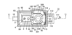
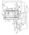
図2及び図3は本発明の好ましい実施形態で使用されるロードロック室とそれに付属する部材とを説明するための概略構成図であり、特に図2は図3のX1−X1線横断面図であり、図3は図2のY1−Y1線縦断面図である。   2 and 3 are schematic configuration diagrams for explaining a load lock chamber and members attached thereto used in a preferred embodiment of the present invention. In particular, FIG. 2 is a cross-sectional view taken along line X1-X1 of FIG. FIG. 3 is a longitudinal sectional view taken along line Y1-Y1 of FIG.

図2及び図3に示す通り、ロードロック室1はSi等の半導体のウエハ101を搭載するボート10を収容可能な予備室の一例であり、開口(後述の開口91)を介して処理炉19の処理室と気密に連通するように配置されている。ロードロック室1内にはボート10を昇降させる昇降機構2が設けられている。ロードロック室1内には熱反射機能を具備した仕切板16が設けられており、ロードロック室1が仕切板16により、昇降機構2を収容する昇降機構室52と、ボート10を収容するボート室51とに分離されている。   As shown in FIGS. 2 and 3, the load lock chamber 1 is an example of a spare chamber capable of accommodating a boat 10 on which a semiconductor wafer 101 such as Si is mounted, and a processing furnace 19 is provided via an opening (an opening 91 described later). It arrange | positions so that it may communicate with the process chamber of airtight. An elevating mechanism 2 that elevates and lowers the boat 10 is provided in the load lock chamber 1. A partition plate 16 having a heat reflecting function is provided in the load lock chamber 1, and the load lock chamber 1 uses the partition plate 16 to move the lift mechanism chamber 52 that houses the lifting mechanism 2 and the boat that houses the boat 10. It is separated from the chamber 51.

ロードロック室1の側壁62のボート室51側には開口91が設けられており、開口91にはゲートバルブ17が取り付けられている。基板処理装置100では、開口91とゲートバルブ17とを介して、ウエハ101をボート10に搭載したり、ボート10からウエハ101を取り出すことができるようになっている。   An opening 91 is provided on the side of the load lock chamber 1 on the side of the boat chamber 51, and the gate valve 17 is attached to the opening 91. In the substrate processing apparatus 100, the wafer 101 can be mounted on the boat 10 and the wafer 101 can be taken out from the boat 10 through the opening 91 and the gate valve 17.

ロードロック室1上には処理炉19が設けられている。処理炉19は、ボート10を収容可能な処理室(図示略)と、当該処理室内を加熱するヒータ等の加熱手段(図示略)とを有しており、当該処理室でボート10に搭載されたウエハ101を熱処理することができるようになっている。   A processing furnace 19 is provided on the load lock chamber 1. The processing furnace 19 has a processing chamber (not shown) in which the boat 10 can be accommodated, and heating means (not shown) such as a heater for heating the processing chamber, and is mounted on the boat 10 in the processing chamber. The wafer 101 can be heat-treated.

処理炉19とボート室51との間の天井壁65には開口92が設けられており、開口92にはゲートバルブ18が取り付けられている。基板処理装置100では、開口92とゲートバルブ18とを介して、ボート10をロードロック室1から処理炉19の処理室内に導入したり、処理炉19の処理室からボート10を取り出すことができるようになっている。   An opening 92 is provided in the ceiling wall 65 between the processing furnace 19 and the boat chamber 51, and the gate valve 18 is attached to the opening 92. In the substrate processing apparatus 100, the boat 10 can be introduced into the processing chamber of the processing furnace 19 from the load lock chamber 1 and the boat 10 can be taken out from the processing chamber of the processing furnace 19 through the opening 92 and the gate valve 18. It is like that.

昇降機構室52には、ボート10を上下方向の移動させる昇降機構2が設けられている。昇降機構2は、移動ブロック3、ボールネジ4、ガイド5、ベアリング6,7、モータ8、磁気シールユニット9を主な構成部品として構成されている。ボールネジ4及びガイド5は、底壁66に取り付けられた基台71と天井壁65に取り付けられた基台72との間に垂直に設けられている。ボールネジ4の下端は基台71内に取り付けられたベアリング7によって回転可能に支持され、かつ、ボールネジ4の上端は基台72内に取り付けられたベアリング6によって回転可能に支持されており、ボールネジ4の先端は磁気シールユニット9に取り付けられている。   The elevating mechanism chamber 52 is provided with an elevating mechanism 2 that moves the boat 10 in the vertical direction. The elevating mechanism 2 includes a moving block 3, a ball screw 4, a guide 5, bearings 6, 7, a motor 8, and a magnetic seal unit 9 as main components. The ball screw 4 and the guide 5 are provided vertically between a base 71 attached to the bottom wall 66 and a base 72 attached to the ceiling wall 65. The lower end of the ball screw 4 is rotatably supported by a bearing 7 attached in a base 71, and the upper end of the ball screw 4 is rotatably supported by a bearing 6 attached in a base 72. Is attached to the magnetic seal unit 9.

ボールネジ4は磁気シールユニット9を介してモータ8に接続されている。モータ8の作動でボールネジ4が回転すると、ボールネジ4とかみ合って取り付けられているナット31(軸受け)と移動ブロック3とが上下動し、それによって移動ブロック3に取り付けられているアーム81が上下動してボート10も上下動するようになっている。   The ball screw 4 is connected to a motor 8 through a magnetic seal unit 9. When the ball screw 4 is rotated by the operation of the motor 8, the nut 31 (bearing) and the moving block 3 which are attached to mesh with the ball screw 4 move up and down, and thereby the arm 81 attached to the moving block 3 moves up and down. The boat 10 is also moved up and down.

なお、ボート10はアーム81上に取り付けられたボート載置部82上に載置されており、アーム81は、仕切板16の中央に垂直に設けられたスリット161を水平方向に貫通した状態で設けられている。移動ブロック3には、ナット31に加えてナット32(軸受け)も設けられており、ナット32はガイド5と共働して移動ブロック3の上下動を案内するようになっている。   The boat 10 is mounted on a boat mounting portion 82 mounted on an arm 81, and the arm 81 penetrates a slit 161 provided vertically in the center of the partition plate 16 in a horizontal direction. Is provided. In addition to the nut 31, the moving block 3 is also provided with a nut 32 (bearing). The nut 32 cooperates with the guide 5 to guide the vertical movement of the moving block 3.

ボート室51には3枚の吸熱板310,320,330が設けられている。吸熱板310,320,330は所定の幅と長さとを有した板状の部材であり、表面にはほとんど凹凸がなく表面が平坦面となっている。吸熱板310,320,330は光の波長を効率よく熱交換するのに放射率の高い材料で構成されている(吸熱板310,320,330は板状の部材に対し放射率の高い材料をコーティングしたもので構成されてもよい。)。吸熱板310,320,330の裏面には冷媒管311,321,331が張り合わせられており、冷媒管311,321,331に冷媒を流通させることで吸熱板310,320,330を冷却することができるようになっている。   The boat chamber 51 is provided with three heat absorbing plates 310, 320, and 330. The heat absorbing plates 310, 320, and 330 are plate-like members having a predetermined width and length, and the surface has almost no unevenness and the surface is a flat surface. The endothermic plates 310, 320, and 330 are made of a material having a high emissivity for efficiently exchanging the wavelength of light (the endothermic plates 310, 320, and 330 are made of a material having a high emissivity relative to the plate-like member). It may consist of a coating.) Refrigerant tubes 311, 321, and 331 are attached to the back surfaces of the heat absorbing plates 310, 320, and 330, and the heat absorbing plates 310, 320, and 330 can be cooled by circulating the refrigerant through the refrigerant tubes 311, 321, and 331. It can be done.

図2に示す通り、吸熱板310はロードロック室1の側壁61に沿って配置されており、両側部が略直角に屈曲している。吸熱板320と吸熱板330とは対向配置されており、吸熱板320はロードロック室1の開口91を閉塞するように側壁62に沿って配置されており、吸熱板330はロードロック室1の側壁64に沿って配置されている。吸熱板320,330はともに一方の端部がボート10の外周に沿ってやや屈曲している。   As shown in FIG. 2, the heat absorbing plate 310 is disposed along the side wall 61 of the load lock chamber 1, and both side portions are bent at substantially right angles. The endothermic plate 320 and the endothermic plate 330 are disposed to face each other, the endothermic plate 320 is disposed along the side wall 62 so as to close the opening 91 of the load lock chamber 1, and the endothermic plate 330 is disposed in the load lock chamber 1. Arranged along the side wall 64. One end of each of the heat absorbing plates 320 and 330 is slightly bent along the outer periphery of the boat 10.

図3に示す通り、ロードロック室1の下部には、吸熱板320,330をボート室51と昇降機構室52との間で移動させる移動機構340,350が設けられている。移動機構340は吸熱板320を、移動機構350は吸熱板330を移動させるようになっている。   As shown in FIG. 3, moving mechanisms 340 and 350 for moving the heat absorbing plates 320 and 330 between the boat chamber 51 and the elevating mechanism chamber 52 are provided below the load lock chamber 1. The moving mechanism 340 moves the heat absorbing plate 320, and the moving mechanism 350 moves the heat absorbing plate 330.

仕切板16の側壁62側には垂直方向に延在するスリット162が形成されている。移動機構340を作動させると、スリット162を介在させた状態で、吸熱板320をボート室51と昇降機構室52との間でスライド移動させることができるようになっている(図2中点線参照)。   A slit 162 extending in the vertical direction is formed on the side wall 62 side of the partition plate 16. When the moving mechanism 340 is operated, the heat absorbing plate 320 can be slid between the boat chamber 51 and the lifting mechanism chamber 52 with the slit 162 interposed (see the dotted line in FIG. 2). ).

仕切板16の側壁64側にも垂直方向に延在するスリット163が形成されている。移動機構350を作動させると、スリット163を介在させた状態で、吸熱板330をボート室51と昇降機構室52との間でスライド移動させることができるようになっている(図2中点線参照)。   A slit 163 extending in the vertical direction is also formed on the side wall 64 side of the partition plate 16. When the moving mechanism 350 is operated, the heat absorbing plate 330 can be slid between the boat chamber 51 and the lifting mechanism chamber 52 with the slit 163 interposed (see the dotted line in FIG. 2). ).

ロードロック室1の側壁61側には、N2等の不活性ガスをロードロック室1に供給する不活性ガス供給ライン11が接続されている。不活性ガス供給ライン11は、不活性ガス供給管111〜115を備えている。不活性ガス供給管111は2本の不活性ガス供給管112,113に分岐している。不活性ガス供給管112,113はそれぞれ側壁61を貫通してロードロック室1内に至っており、そのロードロック室1内で垂直方向に延在する不活性ガス供給管114,115に連通している。不活性ガス供給管114,115にはそれぞれ複数の孔116が垂直方向に設けられている。 An inert gas supply line 11 for supplying an inert gas such as N 2 to the load lock chamber 1 is connected to the side wall 61 side of the load lock chamber 1. The inert gas supply line 11 includes inert gas supply pipes 111 to 115. The inert gas supply pipe 111 is branched into two inert gas supply pipes 112 and 113. The inert gas supply pipes 112 and 113 pass through the side wall 61 to reach the load lock chamber 1, and communicate with inert gas supply pipes 114 and 115 extending in the vertical direction in the load lock chamber 1. Yes. The inert gas supply pipes 114 and 115 are each provided with a plurality of holes 116 in the vertical direction.

不活性ガス供給管111の途中には流量計118が設けられており、不活性ガス供給管111からロードロック室1への不活性ガスの供給量を調整することができるようになっている。   A flow meter 118 is provided in the middle of the inert gas supply pipe 111 so that the supply amount of the inert gas from the inert gas supply pipe 111 to the load lock chamber 1 can be adjusted.

不活性ガス供給管111から流入した不活性ガスは、不活性ガス供給管114,115の各孔116からシャワー方式でボート10とウエハ101とに向かって供給されるようになっており、その後は仕切板16のスリット161を通過して昇降機構室52内に流入するようになっている。   The inert gas flowing in from the inert gas supply pipe 111 is supplied from the holes 116 of the inert gas supply pipes 114 and 115 toward the boat 10 and the wafer 101 by a shower method, and thereafter It passes through the slit 161 of the partition plate 16 and flows into the elevating mechanism chamber 52.

更にロードロック室1の側壁61側には、冷媒管311,321,331に冷媒を供給する冷媒供給管360と、冷媒管311,321,331の冷媒を排出する冷媒排出管370とが接続されている。冷媒供給管360と冷媒排出管370は冷媒管311,321,331に接続されており、冷媒が冷媒供給管360から冷媒管311,321,331を流通して(経由して)冷媒排出管370から排出されるようになっている。   Further, a refrigerant supply pipe 360 that supplies refrigerant to the refrigerant pipes 311, 321, and 331 and a refrigerant discharge pipe 370 that discharges the refrigerant in the refrigerant pipes 311, 321, and 331 are connected to the side wall 61 side of the load lock chamber 1. ing. The refrigerant supply pipe 360 and the refrigerant discharge pipe 370 are connected to the refrigerant pipes 311, 321, 331, and the refrigerant flows from the refrigerant supply pipe 360 through the refrigerant pipes 311, 321, 331 (via the refrigerant pipe) 370. It comes to be discharged from.

ロードロック室1の側壁63には、これを貫通する真空排気ライン121が設けられている。真空排気ライン121の途中にはエアバルブ13が設けられている。真空排気ライン121のエアバルブ13の手前側には大気圧ベントライン14が接続されている。大気圧ベントライン14の先端は実質的に大気圧となっている。大気圧ベントライン14の途中にはエアバルブ15が設けられている。基板処理装置100では、エアバルブ13,15により、真空排気ライン121と大気圧ベントライン14との間で排気を切り換えることができるようになっている。   The side wall 63 of the load lock chamber 1 is provided with a vacuum exhaust line 121 penetrating therethrough. An air valve 13 is provided in the middle of the vacuum exhaust line 121. An atmospheric pressure vent line 14 is connected to the front side of the air valve 13 of the vacuum exhaust line 121. The tip of the atmospheric pressure vent line 14 is substantially at atmospheric pressure. An air valve 15 is provided in the middle of the atmospheric pressure vent line 14. In the substrate processing apparatus 100, the exhaust can be switched between the vacuum exhaust line 121 and the atmospheric pressure vent line 14 by the air valves 13 and 15.

真空排気ライン121は真空排気ライン120に接続されており、真空排気ライン120には真空ポンプ80が接続されている。真空排気ライン120の途中には、真空排気ライン122の一端が接続され、真空排気ライン122の他端は処理炉19の処理室に接続されている。真空排気ライン122の途中にはエアバルブ123が設けられている。   The vacuum exhaust line 121 is connected to the vacuum exhaust line 120, and the vacuum pump 80 is connected to the vacuum exhaust line 120. In the middle of the vacuum exhaust line 120, one end of the vacuum exhaust line 122 is connected, and the other end of the vacuum exhaust line 122 is connected to the processing chamber of the processing furnace 19. An air valve 123 is provided in the middle of the vacuum exhaust line 122.

なお、処理炉19には、処理室に処理ガスを供給するガス供給ラインと、処理室に不活性ガスを供給する不活性ガス供給ラインとが接続されており、エアバルブ123を開けた状態で真空ポンプ80を作動させると、処理ガス又は不活性ガスを処理室内に供給しながらその処理室のガス雰囲気を真空排気ライン122から排気することができるようになっている。   Note that a gas supply line for supplying a processing gas to the processing chamber and an inert gas supply line for supplying an inert gas to the processing chamber are connected to the processing furnace 19, and the vacuum is maintained with the air valve 123 opened. When the pump 80 is operated, the gas atmosphere in the processing chamber can be exhausted from the vacuum exhaust line 122 while supplying the processing gas or the inert gas into the processing chamber.

真空排気ライン122の途中には、不活性ガスバラスト配管131が接続されている。不活性ガスバラスト配管131の途中には流量計132が設けられており、不活性ガスバラスト配管131への不活性ガス供給量を調整することができるようになっている。   In the middle of the vacuum exhaust line 122, an inert gas ballast pipe 131 is connected. A flow meter 132 is provided in the middle of the inert gas ballast pipe 131 so that the amount of inert gas supplied to the inert gas ballast pipe 131 can be adjusted.

ロードロック室1の底壁66には、これを貫通して昇降機構室52内に連通する圧力計41が設けられており、ロードロック室1内、そのなかでも特に昇降機構室52内の圧力を測定することができるようになっている。   The bottom wall 66 of the load lock chamber 1 is provided with a pressure gauge 41 that passes through the bottom wall 66 and communicates with the inside of the lift mechanism chamber 52, and the pressure in the load lock chamber 1, particularly the pressure in the lift mechanism chamber 52. Can be measured.

以上の構成では、移動機構340,350、エアバルブ13,15,123、流量計118,132及び圧力計41が制御装置150に接続されている。制御装置150には表示装置151が接続されており、移動機構340,350の動作状況や流量計118,132からの各流量情報、圧力計41からの圧力情報等を表示するようにしている。   In the above configuration, the moving mechanisms 340 and 350, the air valves 13, 15 and 123, the flow meters 118 and 132, and the pressure gauge 41 are connected to the control device 150. A display device 151 is connected to the control device 150 so as to display the operation status of the moving mechanisms 340 and 350, the flow information from the flow meters 118 and 132, the pressure information from the pressure gauge 41, and the like.

また、ロードロック室1排気用の真空ポンプと、処理炉19の処理室排気用の真空ポンプとを1つの真空ポンプ80で兼用しており、これによりコストの低減や装置の簡略化等を図っている。   In addition, the vacuum pump for exhausting the load lock chamber 1 and the vacuum pump for exhausting the processing chamber of the processing furnace 19 are combined with one vacuum pump 80, thereby reducing costs and simplifying the apparatus. ing.

続いて、上記のような構成の基板処理装置100を用いてウエハ101に成膜処理を行う方法について説明する。   Next, a method for forming a film on the wafer 101 using the substrate processing apparatus 100 configured as described above will be described.

なお、基板処理装置100では、処理炉19に関する加熱手段やガス供給ライン、移動機構340,350、エアバルブ13,15,123、真空ポンプ80、流量計118,132、圧力計41等の制御は制御装置150よって行われ、移動機構340,350の動作状況や流量計118,132からの各流量情報、圧力計41からの圧力情報等は制御装置150を介して表示装置151によって表示される。   In the substrate processing apparatus 100, the heating means and the gas supply line for the processing furnace 19, the moving mechanisms 340 and 350, the air valves 13, 15, and 123, the vacuum pump 80, the flow meters 118 and 132, the pressure gauge 41, and the like are controlled. The operation status of the moving mechanisms 340 and 350, the flow rate information from the flow meters 118 and 132, the pressure information from the pressure gauge 41, and the like are displayed on the display device 151 via the control device 150.

(ステップS1)
まず、ゲートバルブ18を閉じた状態で処理炉19の処理室内を所定の温度と雰囲気に保っておき、吸熱板320,330を図2中点線位置に移動させておく。この状態において、ゲートバルブ17を開放状態にする。このとき、エアバルブ13,15は閉じておく。その後、開口91とゲートバルブ17とを介して、ロードロック室1外部の大気圧雰囲気からボート10上に複数のウエハ101を搭載する。
(Step S1)
First, the processing chamber of the processing furnace 19 is maintained at a predetermined temperature and atmosphere with the gate valve 18 closed, and the heat absorbing plates 320 and 330 are moved to the dotted line positions in FIG. In this state, the gate valve 17 is opened. At this time, the air valves 13 and 15 are closed. Thereafter, a plurality of wafers 101 are mounted on the boat 10 from the atmospheric pressure atmosphere outside the load lock chamber 1 through the opening 91 and the gate valve 17.

(ステップS2)
その後、ゲートバルブ17を閉じる。エアバルブ15を閉じたままでエアバルブ13を開き、ロードロック室1内を真空排気ライン121、120を介して真空引きする。
(Step S2)
Thereafter, the gate valve 17 is closed. The air valve 13 is opened with the air valve 15 closed, and the load lock chamber 1 is evacuated through the vacuum exhaust lines 121 and 120.

(ステップS3)
その後、エアバルブ13を閉じ、ロードロック室1内が大気圧以上になるまで不活性ガス供給ライン11から不活性ガスを供給してロードロック室1内を不活性ガス雰囲気にする。その後、不活性ガス供給ライン11から不活性ガスを供給した状態で、エアバルブ15を開き、大気圧ベントライン14から不活性ガスを排気する。
(Step S3)
Thereafter, the air valve 13 is closed, and an inert gas is supplied from the inert gas supply line 11 until the inside of the load lock chamber 1 becomes atmospheric pressure or higher, thereby making the inside of the load lock chamber 1 an inert gas atmosphere. Thereafter, with the inert gas supplied from the inert gas supply line 11, the air valve 15 is opened and the inert gas is exhausted from the atmospheric pressure vent line 14.

この際、大気圧ベントライン14からのパーティクルや酸素の逆流を防止するため、ロードロック室1内が大気圧より若干陽圧(0.05kgf/cm2G程度)となるように、流量計118により不活性ガス供給ライン11から供給する不活性ガスの流量を制御する。流量計118の流量の制御は、圧力計41から入力されたロードロック室1内の圧力情報に応じて制御装置150によって行われる。 At this time, in order to prevent the backflow of particles and oxygen from the atmospheric pressure vent line 14, the flow meter 118 is set so that the inside of the load lock chamber 1 is slightly positive pressure (about 0.05 kgf / cm 2 G) from the atmospheric pressure. Is used to control the flow rate of the inert gas supplied from the inert gas supply line 11. The control of the flow rate of the flow meter 118 is performed by the control device 150 according to the pressure information in the load lock chamber 1 input from the pressure gauge 41.

(ステップS4)
その後、不活性ガス供給ライン11から不活性ガスを供給しつつ大気圧ベントライン14から不活性ガスを排気する。この状態でゲートバルブ18を開き、昇降機構2によりボート10を上昇させて処理炉19の処理室内に導入する。
(Step S4)
Thereafter, the inert gas is exhausted from the atmospheric pressure vent line 14 while supplying the inert gas from the inert gas supply line 11. In this state, the gate valve 18 is opened, and the boat 10 is lifted by the lifting mechanism 2 and introduced into the processing chamber of the processing furnace 19.

ゲートバルブ18を開く際には、圧力計41からのロードロック室1内の圧力情報を制御装置150に入力し、測定したロードロック室1内の圧力値と、予め設定した所定の圧力値又は処理炉19の処理室内の圧力値とを比較し、流量調整計118を制御装置150で制御することによってロードロック室1内の圧力を制御して、処理炉19の処理室内とロードロック室1内との圧力差をできるだけなくすように圧力制御する。   When opening the gate valve 18, the pressure information in the load lock chamber 1 from the pressure gauge 41 is input to the control device 150, and the measured pressure value in the load lock chamber 1 and a predetermined pressure value set in advance or The pressure value in the processing chamber of the processing furnace 19 is compared with the pressure value in the processing chamber 19 and the pressure controller 118 is controlled by the controller 150 to control the pressure in the load lock chamber 1. The pressure is controlled so as to eliminate the pressure difference from the inside as much as possible.

大気ベントライン14に流量計140を設けて大気ベントライン14の流量を調整することによってロードロック室1内の圧力を調整することもできる。   The pressure in the load lock chamber 1 can also be adjusted by providing a flow meter 140 in the atmospheric vent line 14 and adjusting the flow rate of the atmospheric vent line 14.

このように、不活性ガス供給ライン11から不活性ガスを供給しつつ大気圧ベントライン14から不活性ガスを排気する場合には、大気圧ベントライン14からのパーティクルや酸素の逆流を防止するため、ロードロック室1内をベント側(略大気圧)より若干陽圧(0.05kgf/cm2 G程度)となるように設定することが望まれる。 Thus, when exhausting the inert gas from the atmospheric pressure vent line 14 while supplying the inert gas from the inert gas supply line 11, in order to prevent the backflow of particles and oxygen from the atmospheric pressure vent line 14. It is desirable to set the inside of the load lock chamber 1 to be slightly positive pressure (about 0.05 kgf / cm 2 G) from the vent side (substantially atmospheric pressure).

なお、ゲートバルブ18を開いてボート10を処理炉19の処理室内に導入する際に、ロードロック室1の内壁は処理炉19の処理室から漏れ出る輻射熱を受けるが、その輻射熱は常温のボート10やそれに搭載されたウエハ101等で遮られ、ロードロック室1の表面温度の上昇は抑えられる。   When the gate valve 18 is opened and the boat 10 is introduced into the processing chamber of the processing furnace 19, the inner wall of the load lock chamber 1 receives radiant heat leaking from the processing chamber of the processing furnace 19. 10 and the wafer 101 mounted thereon, the rise in the surface temperature of the load lock chamber 1 can be suppressed.

(ステップS5)
その後、ゲートバルブ18を閉じ、処理炉19の処理室において処理ガスを供給しながらボート10に搭載されたウエハ101を加熱し、ウエハ101に成膜処理を行う。
(Step S5)
Thereafter, the gate valve 18 is closed, the wafer 101 mounted on the boat 10 is heated while supplying the processing gas in the processing chamber of the processing furnace 19, and film formation processing is performed on the wafer 101.

成膜処理中、ロードロック室1内では、不活性ガス供給ライン11から不活性ガスを供給しつつ大気圧ベントライン14から不活性ガスを排気する。   During the film forming process, the inert gas is exhausted from the atmospheric pressure vent line 14 while supplying the inert gas from the inert gas supply line 11 in the load lock chamber 1.

この際、大気圧ベントライン14からのパーティクルや酸素の逆流を防止するため、ロードロック室1内を大気圧より若干陽圧(0.05kgf/cm2 G程度)となるように、流量計118により不活性ガス供給ライン11から供給する不活性ガスの流量を制御する。 At this time, in order to prevent the backflow of particles and oxygen from the atmospheric pressure vent line 14, the flow meter 118 is set so that the inside of the load lock chamber 1 is slightly positive pressure (about 0.05 kgf / cm 2 G) from the atmospheric pressure. Is used to control the flow rate of the inert gas supplied from the inert gas supply line 11.

ステップS5では、上記の通りに処理炉19の処理室内においてウエハ101の成膜処理を行うが、その成膜条件として処理炉19の処理室内の温度,圧力を厳密に制御することが重要になる。   In step S5, the wafer 101 is formed in the processing chamber of the processing furnace 19 as described above. It is important to strictly control the temperature and pressure in the processing chamber of the processing furnace 19 as film forming conditions. .

本実施の形態では、処理炉19の処理室内の圧力制御方法として、不活性ガスバラスト方式を採用する。「不活性バラスト方式」とは、真空ポンプ80の排気能力を一定として排気する一方で、真空排気ライン122の途中に接続された不活性ガスバラスト配管131から不活性ガスを流入させ、この不活性ガスの流量を流量計132により制御することによって処理炉19の処理室からの排気量を調整して処理炉19の処理室内の圧力調整を行う方法である。   In the present embodiment, an inert gas ballast system is adopted as a pressure control method in the processing chamber of the processing furnace 19. In the “inert ballast system”, the vacuum pump 80 is exhausted at a constant exhaust capacity, while an inert gas is introduced from an inert gas ballast pipe 131 connected in the middle of the vacuum exhaust line 122. In this method, the flow rate of the gas is controlled by the flow meter 132 to adjust the exhaust amount from the processing chamber of the processing furnace 19 to adjust the pressure in the processing chamber of the processing furnace 19.

なお、不活性ガスバラスト方式に代えて、流量調整バルブ使用(APC)方式を使用することもできる。「APC方式」とは、不活性ガスバラスト配管131から不活性ガスを導入するものではなく、真空排気ライン122に流量調整バルブ160を設け、流量調整バルブ160の開度により真空排気ライン122のコンダクタンスを調整して処理炉19の処理室内の圧力調整を行う方法である。   In place of the inert gas ballast method, a flow rate adjusting valve use (APC) method may be used. The “APC system” does not introduce an inert gas from the inert gas ballast pipe 131, but a flow rate adjusting valve 160 is provided in the vacuum exhaust line 122, and the conductance of the vacuum exhaust line 122 is determined by the opening degree of the flow rate adjusting valve 160. This is a method for adjusting the pressure in the processing chamber of the processing furnace 19.

(ステップS6)
処理炉19の処理室での成膜処理が終了した後に、処理炉19の処理室内の雰囲気を不活性ガス雰囲気とする。
(Step S6)
After the film forming process in the processing chamber of the processing furnace 19 is completed, the atmosphere in the processing chamber of the processing furnace 19 is changed to an inert gas atmosphere.

その一方で、不活性ガス供給ライン11からロードロック室1内に不活性ガスを供給しつつ大気圧ベントライン14から排気し続けておき、ロードロック室1内を不活性ガス雰囲気に維持しておく。   On the other hand, while the inert gas is being supplied from the inert gas supply line 11 into the load lock chamber 1, the exhaust gas is continuously exhausted from the atmospheric pressure vent line 14 to maintain the load lock chamber 1 in an inert gas atmosphere. deep.

これと同時に、移動機構340,350を作動させて吸熱板320,330を図2中実線の位置に移動させ、吸熱板320,330をウエハ101の冷却時の位置に移動させる。また、冷媒を冷媒供給管360から冷媒管311,321,331に供給し、吸熱板310,320,330を冷却しておく。   At the same time, the moving mechanisms 340 and 350 are operated to move the heat absorbing plates 320 and 330 to the positions indicated by solid lines in FIG. 2, and the heat absorbing plates 320 and 330 are moved to the position when the wafer 101 is cooled. Further, the refrigerant is supplied from the refrigerant supply pipe 360 to the refrigerant pipes 311, 321, 331, and the heat absorbing plates 310, 320, 330 are cooled.

この状態で、ゲートバルブ18を開き、昇降機構2によりボート10を下降させて処理炉19の処理室からロードロック室1内に移動させ、その後ゲートバルブ18を閉じる。   In this state, the gate valve 18 is opened, the boat 10 is lowered by the elevating mechanism 2 and moved from the processing chamber of the processing furnace 19 into the load lock chamber 1, and then the gate valve 18 is closed.

ロードロック室1では、不活性ガス供給ライン11から不活性ガスが供給されているから、ボート10がロードロック室1に移動すると、当該不活性ガスがボート10やそれに搭載されたウエハ101等を冷却する。   Since the inert gas is supplied from the inert gas supply line 11 in the load lock chamber 1, when the boat 10 moves to the load lock chamber 1, the inert gas flows into the boat 10, the wafer 101 mounted on the boat 10, and the like. Cooling.

なお、ゲートバルブ18を開く際には、流量計118の流量を制御することによってロードロック室1内の圧力を制御して、処理炉19の処理室内とロードロック室1内との圧力差をできるだけなくすように圧力制御することが好ましい。   When opening the gate valve 18, the pressure in the load lock chamber 1 is controlled by controlling the flow rate of the flow meter 118, and the pressure difference between the processing chamber of the processing furnace 19 and the load lock chamber 1 is set. It is preferable to control the pressure as much as possible.

ここで、ゲートバルブ18が開いてボート10が処理炉19の処理室からロードロック室1に下降する際や下降後においてロードロック室1に滞在する際に、ボート10やそれに搭載されたウエハ101等は輻射熱を発するが、吸熱板310,320,330がロードロック室1の内壁とボート10やそれに搭載されたウエハ101等との間に介在してその輻射熱を受け、ロードロック室1の内壁は当該輻射熱をほとんど受けない。   Here, when the gate valve 18 is opened and the boat 10 descends from the processing chamber of the processing furnace 19 to the load lock chamber 1 or stays in the load lock chamber 1 after descending, the boat 10 and the wafer 101 mounted thereon. Emits radiant heat, but the heat absorbing plates 310, 320, 330 are interposed between the inner wall of the load lock chamber 1 and the boat 10, the wafer 101 mounted on the boat 10, etc., and receive the radiant heat to receive the inner wall of the load lock chamber 1. Receives almost no radiant heat.

また、不活性ガス供給ライン11から供給された不活性ガスは当該輻射熱を受けて温められるが、その不活性ガスは吸熱板310,320,330により熱交換(冷却)されながら吸熱板310,320,330で囲まれた領域中でこれら吸熱板310,320,330に沿って流れ、ボート10やそれに搭載されたウエハ101等を冷却する。   The inert gas supplied from the inert gas supply line 11 is warmed by receiving the radiant heat, and the inert gas is heat-exchanged (cooled) by the heat-absorbing plates 310, 320, and 330, and the heat-absorbing plates 310 and 320. , 330 flows along the heat absorbing plates 310, 320, 330, and cools the boat 10 and the wafer 101 mounted thereon.

(ステップS7)
その後、不活性ガス供給ライン11から不活性ガスを供給しつつ大気圧ベントライン14から不活性ガスを排気しながら、ゲートバルブ17を開き、開口91とゲートバルブ17とを介して、ボート10からロードロック室1外部の大気圧雰囲気中に複数のウエハ101を取り出す。
(Step S7)
Thereafter, the inert gas is supplied from the inert gas supply line 11 and the inert gas is exhausted from the atmospheric pressure vent line 14, the gate valve 17 is opened, and the boat 10 is opened via the opening 91 and the gate valve 17. The plurality of wafers 101 are taken out into the atmospheric pressure atmosphere outside the load lock chamber 1.

ゲートバルブ17を開く際も、流量計118の流量を制御することによってロードロック室1内の圧力を制御して、ロードロック室1内とロードロック1外部の大気圧雰囲気との圧力差をできるだけなくすようにすることが好ましい。   Even when the gate valve 17 is opened, the pressure in the load lock chamber 1 is controlled by controlling the flow rate of the flow meter 118 so that the pressure difference between the load lock chamber 1 and the atmospheric pressure atmosphere outside the load lock 1 is as much as possible. It is preferable to eliminate them.

以上の実施形態では、ロードロック室1内に吸熱板310,320,330が配置され、熱処理後のウエハ101をロードロック室1内で冷却する際に、吸熱板320,330が図2中実線の位置であってウエハ101の周辺の位置に移動するから、ボート10やそれに搭載されたウエハ101等の輻射熱を吸熱板310,320,330で遮断・吸熱することができ、ロードロック室1の内壁は当該輻射熱をほとんど受けず、ロードロック室1の内壁に付着した水分や不純物等はロードロック室1中に浮遊し難い。   In the above embodiment, the heat absorption plates 310, 320, and 330 are disposed in the load lock chamber 1, and when the heat-treated wafer 101 is cooled in the load lock chamber 1, the heat absorption plates 320 and 330 are solid lines in FIG. 2. And the radiant heat of the boat 10 and the wafer 101 mounted on the boat 10 can be cut off and absorbed by the heat absorbing plates 310, 320, 330. The inner wall hardly receives the radiant heat, and moisture, impurities, etc. adhering to the inner wall of the load lock chamber 1 hardly float in the load lock chamber 1.

またこの際に、不活性ガス供給ライン11から供給された不活性ガスは吸熱板310,320,330で吸熱されるから、ロードロック室1内でのガス流れが乱されるようなこともほとんどなく(ガス流れが整えられ)、ロードロック室1内での熱対流の発生を抑えることができる。   At this time, since the inert gas supplied from the inert gas supply line 11 is absorbed by the heat absorbing plates 310, 320, and 330, the gas flow in the load lock chamber 1 is hardly disturbed. (The gas flow is adjusted), and the occurrence of thermal convection in the load lock chamber 1 can be suppressed.

同時に、吸熱板310,320,330がロードロック室1の内壁と熱処理後のボート10やそれに搭載されたウエハ101等との間に介在するから、不活性ガス供給ライン11から供給された不活性ガスは、吸熱板310,320,330によりロードロック室1の内壁の周辺で熱対流を発生させることはほとんどないし、吸熱板310,320,330の表面にはほとんど凹凸が形成されていないから、吸熱板310,320,330に沿って流動しても、吸熱板310,320,330周辺で熱対流を発生させることもほとんどない。   At the same time, the heat absorbing plates 310, 320, and 330 are interposed between the inner wall of the load lock chamber 1 and the heat-treated boat 10 and the wafer 101 mounted thereon, so that the inert gas supplied from the inert gas supply line 11 is provided. The gas hardly generates thermal convection around the inner wall of the load lock chamber 1 by the heat absorbing plates 310, 320, 330, and the surface of the heat absorbing plates 310, 320, 330 has almost no unevenness, Even if it flows along the heat absorbing plates 310, 320, and 330, thermal convection is hardly generated around the heat absorbing plates 310, 320, and 330.

そのため、ロードロック室1の内壁に付着していた水分や不純物等が仮にロードロック室1中に浮遊して当該不活性ガスと混在されたとしても、その水分や不純物等はロードロック室1中を飛散し難くなる。   Therefore, even if moisture, impurities, etc. adhering to the inner wall of the load lock chamber 1 float in the load lock chamber 1 and are mixed with the inert gas, the moisture, impurities, etc. remain in the load lock chamber 1. It becomes difficult to scatter.

以上から、ロードロック室1の内壁に付着していた水分や不純物等が熱処理後のウエハ101やそれを搭載するボート10等に付着するのを防止又は抑止することができ、ひいては製品用のウエハ101が汚染されるのを防止又は抑止することができる。   From the above, it is possible to prevent or deter the moisture, impurities, etc. adhering to the inner wall of the load lock chamber 1 from adhering to the wafer 101 after heat treatment, the boat 10 on which it is mounted, etc. 101 can be prevented or prevented from being contaminated.

ここで、本実施形態に係る基板処理装置100の比較例として、上記構成(吸熱板310,320,330等)を有しない基板処理装置を想定すると、当該基板処理装置は図4及び図5のような構成を有する。図4及び図5は比較例としての基板処理装置のロードロック室を説明するための図であり、特に図4は図5のX7−X7線横断面図であり、図5は図4のY7ーY7線縦断面図である。   Here, as a comparative example of the substrate processing apparatus 100 according to the present embodiment, assuming a substrate processing apparatus that does not have the above configuration (the heat absorbing plates 310, 320, 330, etc.), the substrate processing apparatus is shown in FIGS. The configuration is as follows. 4 and 5 are views for explaining a load lock chamber of a substrate processing apparatus as a comparative example. In particular, FIG. 4 is a cross-sectional view taken along line X7-X7 in FIG. 5, and FIG. 5 is Y7 in FIG. FIG.

図4及び図5を参照すると、比較例としての基板処理装置200では、図2及び図3を参照しながら説明した吸熱板310,320,330、冷媒管311,321,331、移動機構340,350、冷媒供給管360、冷媒排出管370等が設けられていない。   4 and 5, in the substrate processing apparatus 200 as a comparative example, the heat absorbing plates 310, 320, 330, the refrigerant pipes 311, 321, 331, the moving mechanism 340, described with reference to FIGS. 2 and 3. 350, the refrigerant supply pipe 360, the refrigerant discharge pipe 370, and the like are not provided.

そのため、基板処理装置200では、熱処理後においてボート10やそれに搭載されたウエハ101等を処理炉19の処理室からロードロック室1に移動させた際に、ボート10やウエハ101等の輻射熱が直接的にロードロック室1の内壁に放射され、そこに付着していた水分や不純物が活性化して不活性ガス供給ライン11から供給された不活性ガスと混在しながらロードロック室1中で飛散し、冷却中のダミーウエハ101やボート10等に付着する可能性がある。   Therefore, in the substrate processing apparatus 200, when the boat 10 and the wafer 101 mounted thereon are moved from the processing chamber of the processing furnace 19 to the load lock chamber 1 after the heat treatment, the radiant heat of the boat 10 and the wafer 101 is directly applied. The water and impurities adhering to the inner wall of the load lock chamber 1 are activated and scattered in the load lock chamber 1 while being mixed with the inert gas supplied from the inert gas supply line 11. There is a possibility of adhering to the dummy wafer 101 or the boat 10 being cooled.

この状態で、これらダミーウエハ101やボート10等が再度処理炉19の処理室に移動しそこで熱処理を受けた場合には、当該熱処理中のダミーウエハ101やボート10等から水分や不純物等が剥離し、その剥離した水分や不純物等が製品用のウエハ101に付着して製品用のウエハ101が汚染されてしまう。   In this state, when the dummy wafer 101, the boat 10 and the like are moved again to the processing chamber of the processing furnace 19 and subjected to a heat treatment there, moisture, impurities and the like are peeled off from the dummy wafer 101 and the boat 10 and the like during the heat treatment, The peeled moisture and impurities adhere to the product wafer 101 and the product wafer 101 is contaminated.

以上は、本発明の好ましい一実施形態を述べたにすぎず、本発明は上記実施形態に限定されるものではない。
例えば、本発明は、半導体ウエハだけでなく、液晶表示素子を形成するためのガラス基板用ロードロック室にも対応することができる。この場合に、本発明は、ガラス基板がボートまたはカセットに搭載されるタイプのロードロック室にも使用できるが、ウエハやガラス基板を一枚ずつロードロック室内に搬入・搬出する枚葉式のロードロック室にも当然に使用することができる。
The above is only a preferred embodiment of the present invention, and the present invention is not limited to the above embodiment.
For example, the present invention can be applied not only to a semiconductor wafer but also to a glass substrate load lock chamber for forming a liquid crystal display element. In this case, the present invention can also be used in a load lock chamber of a type in which glass substrates are mounted on a boat or cassette, but a single wafer type load for loading and unloading wafers and glass substrates one by one into the load lock chamber. Of course, it can also be used in lock rooms.

本発明の好ましい実施形態で使用される基板処理装置の概略構成を示す斜透視図である。It is a perspective view which shows schematic structure of the substrate processing apparatus used by preferable embodiment of this invention. 本発明の好ましい実施形態で使用されるロードロック室とそれに付属する部材とを説明するための概略構成図であって図3のX1−X1線横断面図である。It is a schematic block diagram for demonstrating the load lock chamber used in preferable embodiment of this invention, and the member attached to it, and is the X1-X1 line cross-sectional view of FIG. 本発明の好ましい実施形態で使用されるロードロック室とそれに付属する部材とを説明するための概略構成図であって、図2のY1−Y1線縦断面図である。It is a schematic block diagram for demonstrating the load lock chamber used in preferable embodiment of this invention, and the member attached to it, Comprising: It is the Y1-Y1 line longitudinal cross-sectional view of FIG. 比較例としての基板処理装置のロードロック室を説明するための図であって、図5のX7−X7線横断面図である。It is a figure for demonstrating the load lock chamber of the substrate processing apparatus as a comparative example, Comprising: It is the X7-X7 line cross-sectional view of FIG. 比較例としての基板処理装置のロードロック室を説明するための図であって、図4のY7−Y7線縦断面図である。It is a figure for demonstrating the load lock chamber of the substrate processing apparatus as a comparative example, Comprising: It is the Y7-Y7 line longitudinal cross-sectional view of FIG.

符号の説明Explanation of symbols

100 基板処理装置
1 ロードロック室
2 昇降機構
3 移動ブロック
4 ボールネジ
5 ガイド
6,7 ベアリング
10 ボート
11 不活性ガス供給ライン
12 真空排気ライン
13,15,123 エアバルブ
14 大気圧ベントライン
16 仕切板
17,18 ゲートバルブ
19 処理炉
31,32 ナット(軸受け)
41 圧力計
51 ボート室
52 昇降機構室
61〜64 側壁
80 真空ポンプ
91,92 開口
101 ウエハ
111〜115 不活性ガス供給管
118,132,140 流量計
131 不活性バラスト配管
150 制御装置
151 表示装置
160 流量調整バルブ
161〜163 スリット
310,320,330 吸熱板
311,321,331 冷媒管
340,350 移動機構
360 冷媒供給管
370 冷媒排出管
DESCRIPTION OF SYMBOLS 100 Substrate processing apparatus 1 Load lock chamber 2 Elevating mechanism 3 Moving block 4 Ball screw 5 Guide 6, 7 Bearing 10 Boat 11 Inert gas supply line 12 Vacuum exhaust line 13, 15, 123 Air valve 14 Atmospheric pressure vent line 16 Partition plate 17, 18 Gate valve 19 Processing furnace 31, 32 Nut (bearing)
41 Pressure gauge 51 Boat chamber 52 Elevating mechanism chamber 61-64 Side wall 80 Vacuum pump 91, 92 Opening 101 Wafer 111-115 Inert gas supply pipe 118, 132, 140 Flowmeter 131 Inactive ballast piping 150 Control device 151 Display device 160 Flow rate adjusting valves 161-163 Slits 310, 320, 330 Endothermic plates 311, 321, 331 Refrigerant pipes 340, 350 Moving mechanism 360 Refrigerant supply pipe 370 Refrigerant discharge pipe

Claims (1)

基板を熱処理する処理室と、
前記処理室内にある前記基板を加熱する加熱手段と、
前記処理室内に所望の処理ガスを供給し、処理室内の雰囲気を排気するガス供給、排気系と、
前記処理室と開口を介して気密に連通するように配置される予備室と、
前記基板を載置すると共に、前記処理室と前記予備室との間で前記開口を経て前記基板を移動させる基板載置手段と、
前記予備室内に不活性ガスを供給する不活性ガス供給手段と、
前記予備室内の雰囲気を排気する予備室排気手段と、
前記予備室内に配置され、予備室内のガス流れの乱れを抑制するための整流手段と、
前記整流手段を前記予備室内の基板冷却時位置とそれ以外の時の位置との間で移動させるための移動手段と、を備え、
前記移動手段は、熱処理後の基板を前記予備室にて冷却する際、前記整流手段を前記基板冷却時位置であって、前記基板の周辺の位置に移動させることを特徴とする基板処理装置。
A processing chamber for heat-treating the substrate;
Heating means for heating the substrate in the processing chamber;
A gas supply for supplying a desired processing gas into the processing chamber and exhausting the atmosphere in the processing chamber; an exhaust system;
A preliminary chamber arranged to communicate with the processing chamber in an airtight manner through an opening;
A substrate mounting means for mounting the substrate and moving the substrate through the opening between the processing chamber and the preliminary chamber;
An inert gas supply means for supplying an inert gas into the preliminary chamber;
Preliminary chamber exhaust means for exhausting the atmosphere in the preliminary chamber;
A rectifying means disposed in the spare chamber for suppressing disturbance of gas flow in the spare chamber;
A moving means for moving the rectifying means between the substrate cooling position in the spare room and a position at other times; and
The substrate processing apparatus, wherein the moving means moves the rectifying means to a position around the substrate at the time of cooling the substrate when cooling the substrate after the heat treatment in the preliminary chamber.
JP2007065074A 2007-03-14 2007-03-14 Substrate processing apparatus Pending JP2008227264A (en)

Priority Applications (1)

Application Number Priority Date Filing Date Title
JP2007065074A JP2008227264A (en) 2007-03-14 2007-03-14 Substrate processing apparatus

Applications Claiming Priority (1)

Application Number Priority Date Filing Date Title
JP2007065074A JP2008227264A (en) 2007-03-14 2007-03-14 Substrate processing apparatus

Publications (2)

Publication Number Publication Date
JP2008227264A true JP2008227264A (en) 2008-09-25
JP2008227264A5 JP2008227264A5 (en) 2010-04-30

Family

ID=39845511

Family Applications (1)

Application Number Title Priority Date Filing Date
JP2007065074A Pending JP2008227264A (en) 2007-03-14 2007-03-14 Substrate processing apparatus

Country Status (1)

Country Link
JP (1) JP2008227264A (en)

Cited By (2)

* Cited by examiner, † Cited by third party
Publication number Priority date Publication date Assignee Title
JP2010231572A (en) * 2009-03-27 2010-10-14 Sumitomo Heavy Ind Ltd Chamber pressure regulating device
US8607752B2 (en) 2008-09-11 2013-12-17 Denso Corporation Valve timing control apparatus

Citations (4)

* Cited by examiner, † Cited by third party
Publication number Priority date Publication date Assignee Title
JPH06260487A (en) * 1993-03-03 1994-09-16 Tokyo Electron Tohoku Ltd Heat-treating device
JPH1022292A (en) * 1996-07-08 1998-01-23 Sony Corp Heat treatment system and heat treatment method using the system
JPH11204447A (en) * 1998-01-12 1999-07-30 Tokyo Electron Ltd Single wafer heat treating system
JP2001068425A (en) * 1999-08-31 2001-03-16 Hitachi Kokusai Electric Inc Method and device for semiconductor thermal process

Patent Citations (4)

* Cited by examiner, † Cited by third party
Publication number Priority date Publication date Assignee Title
JPH06260487A (en) * 1993-03-03 1994-09-16 Tokyo Electron Tohoku Ltd Heat-treating device
JPH1022292A (en) * 1996-07-08 1998-01-23 Sony Corp Heat treatment system and heat treatment method using the system
JPH11204447A (en) * 1998-01-12 1999-07-30 Tokyo Electron Ltd Single wafer heat treating system
JP2001068425A (en) * 1999-08-31 2001-03-16 Hitachi Kokusai Electric Inc Method and device for semiconductor thermal process

Cited By (4)

* Cited by examiner, † Cited by third party
Publication number Priority date Publication date Assignee Title
US8607752B2 (en) 2008-09-11 2013-12-17 Denso Corporation Valve timing control apparatus
US9085997B2 (en) 2008-09-11 2015-07-21 Denso Corporation Valve timing control apparatus
US9759101B2 (en) 2008-09-11 2017-09-12 Denso Corporation Valve timing control apparatus
JP2010231572A (en) * 2009-03-27 2010-10-14 Sumitomo Heavy Ind Ltd Chamber pressure regulating device

Similar Documents

Publication Publication Date Title
US8950999B2 (en) Substrate processing apparatus and particle adhesion preventing method
JP4498362B2 (en) Substrate processing apparatus and semiconductor device manufacturing method
TWI534923B (en) Load interlock
US9460945B2 (en) Substrate processing apparatus for semiconductor devices
US20120083120A1 (en) Substrate processing apparatus and method of manufacturing a semiconductor device
JP2007035874A (en) Vacuum processing system
TW202023932A (en) Side storage pods, equipment front end modules, and methods for operating efems
JP2007095879A (en) Substrate processing equipment
KR100905262B1 (en) Substrate Processing Apparatus and Manufacturing Method for a Semiconductor Device
JP2008227264A (en) Substrate processing apparatus
JP2005064242A (en) Processing system of substrate and heat-treatment method of substrate
JP2004119888A (en) Semiconductor manufacturing apparatus
JPWO2005083760A1 (en) Substrate processing apparatus and semiconductor device manufacturing method
JPH07283288A (en) Processing device
JP2008028305A (en) Substrate processing device
JP6951129B2 (en) Substrate processing equipment, programs and fluid circulation mechanisms, and methods for manufacturing semiconductor equipment
JP2005197471A (en) Substrate processing equipment and temperature control method
JP2011044633A (en) Substrate processing apparatus
JP5224679B2 (en) Substrate processing apparatus, semiconductor device manufacturing method, and substrate processing method
JPWO2019172274A1 (en) Manufacturing method of processing equipment, exhaust system, semiconductor equipment
JP5027430B2 (en) Substrate processing equipment
JP2003092329A (en) Substrate processing system
JP4399279B2 (en) Substrate processing apparatus and IC manufacturing method
JP2010153480A (en) Process of fabricating semiconductor device
JP2006186189A (en) Gas processing and manufacturing apparatus and method therefor

Legal Events

Date Code Title Description
RD05 Notification of revocation of power of attorney

Free format text: JAPANESE INTERMEDIATE CODE: A7425

Effective date: 20100204

RD04 Notification of resignation of power of attorney

Free format text: JAPANESE INTERMEDIATE CODE: A7424

Effective date: 20100210

A521 Written amendment

Free format text: JAPANESE INTERMEDIATE CODE: A523

Effective date: 20100311

A621 Written request for application examination

Free format text: JAPANESE INTERMEDIATE CODE: A621

Effective date: 20100311

A977 Report on retrieval

Free format text: JAPANESE INTERMEDIATE CODE: A971007

Effective date: 20101012

A131 Notification of reasons for refusal

Effective date: 20120705

Free format text: JAPANESE INTERMEDIATE CODE: A131

A02 Decision of refusal

Free format text: JAPANESE INTERMEDIATE CODE: A02

Effective date: 20121025