JP2008202808A - Air conditioner - Google Patents
Air conditioner Download PDFInfo
- Publication number
- JP2008202808A JP2008202808A JP2007036102A JP2007036102A JP2008202808A JP 2008202808 A JP2008202808 A JP 2008202808A JP 2007036102 A JP2007036102 A JP 2007036102A JP 2007036102 A JP2007036102 A JP 2007036102A JP 2008202808 A JP2008202808 A JP 2008202808A
- Authority
- JP
- Japan
- Prior art keywords
- filter
- air
- fan
- suction panel
- indoor unit
- Prior art date
- Legal status (The legal status is an assumption and is not a legal conclusion. Google has not performed a legal analysis and makes no representation as to the accuracy of the status listed.)
- Pending
Links
Images


Abstract
Description
本発明は、駆動式の吸い込みパネルを設けた室内ユニットにおいて、吸い込みパネルの開度位置によって変化する温度センサーの温度差により、フィルタの目詰まり状態を判断し、ファンの回転数を大きく変化させるように制御することによって、フィルタの目詰まりによる風量低下を防止して快適性向上を図る空気調和装置に関するものである。 According to the present invention, in an indoor unit provided with a drive-type suction panel, the clogged state of the filter is judged based on the temperature difference of the temperature sensor that changes depending on the opening position of the suction panel, and the fan speed is greatly changed. The present invention relates to an air conditioner that prevents a decrease in the air volume due to clogging of the filter and thereby improves comfort.
通常、空気調和装置は、室内ユニットの上部に吸い込みパネル、フィルタ、下部に吹出しグリルを設け、吹出口付近にはファン、ファンモータを設けた構成を持っている。 Usually, the air conditioner has a configuration in which a suction panel and a filter are provided in the upper part of the indoor unit, a blow-out grill is provided in the lower part, and a fan and a fan motor are provided in the vicinity of the blow-out opening.
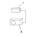
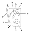
図1は、室内ユニット1と室外ユニット2で構成されたセパレート型空気調和装置の外観を示す図であり、図2は、その室内ユニット1に駆動式の吸い込みパネル3、ファン7、ファンモータ9、フィルタ4、熱交換器5、熱交換器5に取り付けられた温度を検知する温度センサー8などを示す室内ユニットの側面図である。
FIG. 1 is a view showing the appearance of a separate type air conditioner composed of an
以下、この室内ユニット1の内部における動作、作用を説明する。駆動式の吸い込みパネル3がC方向に開き、空気はA方向から吸い込まれ、そしてフィルタ4を通過し、熱交換器5により吸い込んだ空気と熱交換器5中の流体を熱交換し、熱交換された空気をファンモータ9により駆動するファン7により吹出口6からB方向に排出される。
Hereinafter, the operation | movement and effect | action inside this
しかしながら、上記の構成による室内ユニットは、ほこりなどを取るフィルタが、多くのほこりにより目詰まりをおこした状態になる場合がある。これより室内ユニットから吹き出される風量が減少し、本来の送風性能が確保できなくなる。さらに冷房時の冷風・暖房時の温風の到達距離が小さくなり部屋の快適性が悪化するなどと言う課題を有していた。 However, in the indoor unit configured as described above, a filter that removes dust or the like may be clogged with a lot of dust. As a result, the amount of air blown from the indoor unit is reduced, and the original air blowing performance cannot be ensured. Furthermore, the reach of cold air during cooling and warm air during heating is reduced, and the comfort of the room deteriorates.
この課題を解決するものとして、運転時間の累積値に応じてファンモータの回転数を切り換えるもの(例えば、特許文献1参照)や、ファンモータの回転数で目詰まりを推定し回転数を制御するもの(例えば、特許文献2参照)などがある。
本発明は、上記課題を解決する一手法に関するもので、吸い込みパネルの開度位置の変化による温度センサーの温度差により目詰まり状態を判断し、室内ユニットにおいてフィルタが目詰まりした場合においても、送風性能を確保することを目的とする。 The present invention relates to a technique for solving the above-described problem. Even when a filter is clogged in an indoor unit by judging a clogged state based on a temperature difference of a temperature sensor due to a change in the opening position of the suction panel, the air blower The purpose is to ensure performance.
上記課題を解決するために、本発明の室内ユニットは、吸い込みパネルの開度位置による温度センサーの温度差によりフィルタの目詰まりの状態(空気を吸引してほこりなどがたまった状態)を判断して風量低下した場合において、ファンの回転数を大きく変化させて風量を回復させるように制御するものである。 In order to solve the above-mentioned problem, the indoor unit of the present invention determines the clogged state of the filter (the state where dust is collected by sucking air) based on the temperature difference of the temperature sensor depending on the opening position of the suction panel. When the air volume is reduced, control is performed so that the air volume is recovered by greatly changing the rotational speed of the fan.
これによって、室内ユニットのフィルタの目詰まりによって、吸い込み空気が減少するため、吹き出される空気の風量も大きく減少していたが、吸い込みパネル位置による温度センサーの温度差により目詰まりを判断してファンの回転数を大きく変化させることによ
り、風量を回復し本来の風量に増加させることができるものである。
As a result, the suction air is reduced due to clogging of the filter of the indoor unit, and the air volume of the blown air is also greatly reduced. However, the fan is judged by the temperature difference of the temperature sensor depending on the suction panel position. The air volume can be recovered and increased to the original air volume by greatly changing the number of rotations.
また、本発明の室内ユニットは、ファンモータ運転開始から一定時間後にフィルタの目詰まりを判断するように制御するものである。これによって、室内ユニットと室外ユニットで構成される空気調和装置において、冷房あるいは暖房運転において、ファンモータ運転開始から運転が安定した状態、つまり、一定時間後にフィルタの目詰まり状態を判断することにより、安定した状態で温度差も検出できるようになり、正確に目詰まり状態を判断することができるものである。 Further, the indoor unit of the present invention controls so as to determine whether the filter is clogged after a predetermined time from the start of the fan motor operation. Thereby, in the air conditioner composed of the indoor unit and the outdoor unit, in the cooling or heating operation, the operation is stable from the start of the fan motor operation, that is, by determining the clogged state of the filter after a certain time, The temperature difference can be detected in a stable state, and the clogged state can be accurately determined.
また、本発明の室内ユニットは、ファンモータの一定累計時間後にフィルタの目詰まりを判断するように制御するものである。これによって、目詰まりはファンモータ運転時間により多くなるため、ファンモータの運転した累計時間後に室内ユニットのフィルタの目詰まり状態を判断することにより、最適に目詰まり状態を判断することができるものである。 Further, the indoor unit of the present invention controls to determine whether the filter is clogged after a certain cumulative time of the fan motor. As a result, the clogging increases with the fan motor operating time, so that the clogging state can be optimally determined by determining the clogging state of the filter of the indoor unit after the cumulative time of operation of the fan motor. is there.
また、本発明の室内ユニットは、フィルタの目詰まりを判断した場合に吸い込みパネルの開度を大きく変化するように制御するものである。これによって、室内ユニットのフィルタの目詰まり状態を解消して風量を回復し増加させることができるものである。 Moreover, the indoor unit of the present invention controls the opening degree of the suction panel so as to change greatly when it is determined that the filter is clogged. Thereby, the clogged state of the filter of the indoor unit can be eliminated, and the air volume can be recovered and increased.
本発明の室内ユニットによれば、吸い込みパネルの開度位置で温度センサーの温度差によりの目詰まりを判断してファンの回転数を大きく変化させる制御は、フィルタが目詰まりした場合に風量を回復し、室内ユニットの送風性能を維持・向上させることができる。また、フィルタが目詰まりした場合(風量が減少した場合)にファンの回転数を大きくするため、風量を回復することができる。 According to the indoor unit of the present invention, the control for judging the clogging due to the temperature difference of the temperature sensor at the opening position of the suction panel and greatly changing the fan rotation speed restores the air volume when the filter is clogged. In addition, the air blowing performance of the indoor unit can be maintained and improved. Further, when the filter is clogged (when the air volume is decreased), the fan speed is increased, so that the air volume can be recovered.
第1の発明は、吸い込みパネル位置による温度センサーの温度差によってファンの回転数を変化させる制御、つまり吸い込みパネルの位置によって吸い込み風量が変化するため、吸い込みパネル位置それぞれの温度センサー値が発生する。それぞれの吸い込みパネル位置による温度センサー値の温度差を比較する。温度センサーの温度差を考えると、フィルタに目詰まりしていない場合は吸い込み風量が変化するため温度差が大きくなる。フィルタが目詰まり(フィルタにごみなどが付き)している場合は吸い込み風量の変化幅が小さくなるため温度差も小さくなる。これより吸い込みパネル開度位置の温度センサーにおける温度差により、目詰まり状態を判断する。 In the first aspect of the invention, since the amount of suction air changes depending on the control of changing the rotation speed of the fan according to the temperature difference of the temperature sensor depending on the suction panel position, that is, the position of the suction panel, the temperature sensor value for each suction panel position is generated. Compare the temperature difference of the temperature sensor value by each suction panel position. Considering the temperature difference of the temperature sensor, if the filter is not clogged, the intake air volume changes and the temperature difference increases. If the filter is clogged (dust is attached to the filter), the change in the intake air volume will be small and the temperature difference will be small. From this, the clogged state is determined from the temperature difference in the temperature sensor at the suction panel opening position.
そして、目詰まりしていると判断した場合は、ファンの回転数を大きくし、空気の吸い込み風量が増加するため、吹き出し風量も増加し、目詰まりしたフィルタにより風量が減少することを補うあるいは風量を増加することができる。また、風量を従来と同等に戻した場合は、騒音も同等にすることができる。 If it is determined that the air is clogged, the fan speed is increased and the air intake air volume increases, so that the blown air volume also increases and compensates for the decrease in the air volume due to the clogged filter or the air volume. Can be increased. Further, when the air volume is returned to the conventional level, the noise can also be made equal.
第2の発明は、ファンモータ運転開始から一定時間後に目詰まりを判断する制御、つまり、冷房運転あるいは暖房運転が安定した状態にある時間経過後に、温度センサーの温度差を測定して判断することにより、正確に目詰まりの状態を判断することができる。 The second invention is a control for judging clogging after a certain time from the start of the fan motor operation, that is, judging by measuring the temperature difference of the temperature sensor after a lapse of time in which the cooling operation or the heating operation is stable. Thus, the clogging state can be accurately determined.
第3の発明は、ファンモータ運転開始から一定累計運転時間後に目詰まりを判断する制御、つまり、冷房運転あるいは暖房運転時のファンモータの運転累計時間後において温度センサーの温度差を判断することにより、最適に目詰まりした状態にて判断することができる。 According to a third aspect of the present invention, control for determining clogging after a certain cumulative operation time from the start of fan motor operation, that is, by determining the temperature difference of the temperature sensor after the cumulative operation time of the fan motor during cooling operation or heating operation. It can be judged in an optimally clogged state.
第4の発明は、温度センサーの温度差により目詰まりを判断した後、吸い込みパネルの駆動位置により風量を変化させる制御、つまり目詰まり時に風量を確保するため吸い込みパネルを開いて風量を回復あるいは増加させる。これより吸い込みパネルの開度位置により、空気の吸い込み風量を増加させて、吹き出し風量を増加させて、目詰まりしたフィルタにより風量が減少することを補い従来の風量を確保することができる。 In the fourth aspect of the invention, after the clogging is determined based on the temperature difference of the temperature sensor, the air volume is changed depending on the driving position of the suction panel, that is, the suction panel is opened to recover or increase the air volume in order to secure the air volume when clogged. Let From this, it is possible to increase the amount of air sucked in by the opening position of the suction panel, to increase the amount of blown air, and to compensate for the decrease in the amount of air by the clogged filter, thereby securing the conventional air volume.
(実施の形態)
図2は、本発明の実施の形態における室内ユニットの側面断面図を示すものである。室内ユニット1が運転する場合は、駆動する吸い込みパネル3がC方向に開き、ファン7を運転させ、空気は、A方向などから吸入され、フィルタ4を通過して熱交換器5を通り、吹出口6からファン7によりB方向に吹き出される。
(Embodiment)
FIG. 2 is a side sectional view of the indoor unit in the embodiment of the present invention. When the
図3は、温度センサー8による温度測定を行う測定位置D、Eを示している。吸い込みパネル3が駆動され、測定位置D、Eに移動すると、それぞれの位置で温度センサー8による温度測定が行われる。
FIG. 3 shows measurement positions D and E where temperature measurement is performed by the temperature sensor 8. When the
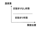
測定位置Dと測定位置Eにおいて温度センサー8により温度を測定すると、それぞれの吸い込みパネル開度において検出される温度センサー8の温度には温度差が発生する。この時、図4に示すように、開度位置による温度差が小さければ目詰まりしている状態と判断し、温度差が大きければ目詰まりしていない状態と判断する。この目詰まりした状態の時に回転数を大きくして風量を回復あるいは増加させるように制御する。 When the temperature is measured by the temperature sensor 8 at the measurement position D and the measurement position E, a temperature difference occurs in the temperature of the temperature sensor 8 detected at each suction panel opening. At this time, as shown in FIG. 4, if the temperature difference due to the opening position is small, it is judged as clogged, and if the temperature difference is large, it is judged as not clogged. In this clogged state, the rotational speed is increased to control the air volume to be recovered or increased.
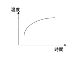
なお、図5は運転開始からのセンサー温度の変化を示している。図5に示されるように、目詰まりを判断するために、運転開始から一定時間後に温度差を測定して、図4の温度差により目詰まりを判断して回転数を変化させるようにしてもよい。 FIG. 5 shows a change in sensor temperature from the start of operation. As shown in FIG. 5, in order to judge clogging, a temperature difference is measured after a certain time from the start of operation, and clogging is judged based on the temperature difference shown in FIG. Good.
また、図6は運転時間と目詰まりの度合いとの関係を示している。図6に示されるように、目詰まりを判断するために、運転開始から一定累計時間後に温度差を測定して、図4の温度差により目詰まりを判断するようにしてもよい。 FIG. 6 shows the relationship between the operation time and the degree of clogging. As shown in FIG. 6, in order to determine clogging, a temperature difference may be measured after a certain cumulative time from the start of operation, and clogging may be determined from the temperature difference in FIG.
さらに、目詰まりした場合において、吸い込みパネル3開度を図3のように開度Dから開度Eにすることにより風量を回復するあるいは大きくすることもできる。
Further, in the case of clogging, the air volume can be recovered or increased by changing the opening degree of the
以上のように、本発明にかかるファンモータの制御は、吸い込みパネルの開度位置の変化により変化する温度センサーの温度差によって、フィルタ目詰まり状態を判断し風量を回復することが可能となり、空気調和装置以外の用途にも適用できる。 As described above, the control of the fan motor according to the present invention makes it possible to determine the filter clogging state and recover the air volume based on the temperature difference of the temperature sensor that changes due to the change in the opening position of the suction panel. It can be applied to uses other than the harmony device.
1 室内ユニット
2 室外ユニット
3 吸い込みパネル
4 フィルタ
5 熱交換器
6 吹出口
7 ファン
8 温度センサー
9 ファンモータ
A 空気方向
B 吹き出し方向
C 駆動方向
D 駆動位置
E 駆動位置
DESCRIPTION OF
Claims (4)
Priority Applications (1)
| Application Number | Priority Date | Filing Date | Title |
|---|---|---|---|
| JP2007036102A JP2008202808A (en) | 2007-02-16 | 2007-02-16 | Air conditioner |
Applications Claiming Priority (1)
| Application Number | Priority Date | Filing Date | Title |
|---|---|---|---|
| JP2007036102A JP2008202808A (en) | 2007-02-16 | 2007-02-16 | Air conditioner |
Publications (1)
| Publication Number | Publication Date |
|---|---|
| JP2008202808A true JP2008202808A (en) | 2008-09-04 |
Family
ID=39780513
Family Applications (1)
| Application Number | Title | Priority Date | Filing Date |
|---|---|---|---|
| JP2007036102A Pending JP2008202808A (en) | 2007-02-16 | 2007-02-16 | Air conditioner |
Country Status (1)
| Country | Link |
|---|---|
| JP (1) | JP2008202808A (en) |
Cited By (8)
| Publication number | Priority date | Publication date | Assignee | Title |
|---|---|---|---|---|
| CN103940039A (en) * | 2014-04-03 | 2014-07-23 | 美的集团股份有限公司 | Air conditioner and judgment method of operating state of air conditioner |
| CN106052054A (en) * | 2016-07-13 | 2016-10-26 | 珠海格力电器股份有限公司 | Man sensor mechanism and air conditioner |
| DE102016109611A1 (en) | 2015-06-01 | 2016-12-08 | Fanuc Corporation | A motor drive device and method for reporting a malfunction in fluid flow in a heat sink |
| CN106989489A (en) * | 2017-04-19 | 2017-07-28 | 珠海格力电器股份有限公司 | Air-conditioning filter device changes based reminding method, device and air-conditioning |
| JP2017142013A (en) * | 2016-02-10 | 2017-08-17 | 三菱電機株式会社 | Controller, control system and program |
| CN107238182A (en) * | 2017-06-27 | 2017-10-10 | 珠海格力电器股份有限公司 | Air conditioner blower control method, system and air conditioner |
| CN111102692A (en) * | 2019-12-25 | 2020-05-05 | 珠海格力电器股份有限公司 | Air conditioner control method and device and air conditioner |
| CN111998384A (en) * | 2020-08-27 | 2020-11-27 | 广州龙鑫蓄热工业炉有限公司 | Automatic timing adjusting method for heat accumulating type burner |
-
2007
- 2007-02-16 JP JP2007036102A patent/JP2008202808A/en active Pending
Cited By (12)
| Publication number | Priority date | Publication date | Assignee | Title |
|---|---|---|---|---|
| CN103940039A (en) * | 2014-04-03 | 2014-07-23 | 美的集团股份有限公司 | Air conditioner and judgment method of operating state of air conditioner |
| DE102016109611A1 (en) | 2015-06-01 | 2016-12-08 | Fanuc Corporation | A motor drive device and method for reporting a malfunction in fluid flow in a heat sink |
| US10032686B2 (en) | 2015-06-01 | 2018-07-24 | Fanuc Corporation | Motor drive device and method capable of notifying malfunction in fluid flow in heat sink |
| DE102016109611B4 (en) | 2015-06-01 | 2024-03-07 | Fanuc Corporation | Motor drive device and method for reporting a malfunction in fluid flow in a heat sink |
| JP2017142013A (en) * | 2016-02-10 | 2017-08-17 | 三菱電機株式会社 | Controller, control system and program |
| CN106052054A (en) * | 2016-07-13 | 2016-10-26 | 珠海格力电器股份有限公司 | Man sensor mechanism and air conditioner |
| CN106989489A (en) * | 2017-04-19 | 2017-07-28 | 珠海格力电器股份有限公司 | Air-conditioning filter device changes based reminding method, device and air-conditioning |
| CN107238182A (en) * | 2017-06-27 | 2017-10-10 | 珠海格力电器股份有限公司 | Air conditioner blower control method, system and air conditioner |
| CN107238182B (en) * | 2017-06-27 | 2018-11-30 | 珠海格力电器股份有限公司 | Air conditioner blower control method, system and air conditioner |
| CN111102692A (en) * | 2019-12-25 | 2020-05-05 | 珠海格力电器股份有限公司 | Air conditioner control method and device and air conditioner |
| CN111102692B (en) * | 2019-12-25 | 2021-05-04 | 珠海格力电器股份有限公司 | Air conditioner control method and device and air conditioner |
| CN111998384A (en) * | 2020-08-27 | 2020-11-27 | 广州龙鑫蓄热工业炉有限公司 | Automatic timing adjusting method for heat accumulating type burner |
Similar Documents
| Publication | Publication Date | Title |
|---|---|---|
| JP2008202808A (en) | Air conditioner | |
| CN109323330A (en) | A kind of air conditioner indoor unit, control method, control device | |
| KR20100051954A (en) | Indoor unit for air conditioning apparatus | |
| JP2008281247A (en) | Operation control method of air conditioner | |
| JP5194349B2 (en) | Air conditioner | |
| JP4698726B2 (en) | Floor-standing air conditioner | |
| JPH1096546A (en) | Condensed water detector for air conditioner and its method | |
| JP2003322380A (en) | Air-conditioning system | |
| JP6960565B2 (en) | Air conditioner | |
| JP3952309B2 (en) | Air cleaner | |
| JP5723734B2 (en) | Air conditioner | |
| JP2019045025A (en) | Air conditioner | |
| JPWO2019003511A1 (en) | Air conditioner | |
| JP6053563B2 (en) | Heat exchange ventilator | |
| JP5053128B2 (en) | Circulator | |
| JP2006275310A (en) | Air conditioner | |
| JP6998506B2 (en) | Air conditioner | |
| WO2018163548A1 (en) | Air conditioner | |
| JPWO2018230128A1 (en) | Air conditioner | |
| JP2014055681A (en) | Air cleaner | |
| WO2019021595A1 (en) | Air conditioner | |
| JP4807149B2 (en) | Air conditioner | |
| JP2007198636A (en) | Integrated air conditioner | |
| JP3748964B2 (en) | Air conditioner | |
| JP6846598B2 (en) | Air conditioner |