JP5053128B2 - Circulator - Google Patents
Circulator Download PDFInfo
- Publication number
- JP5053128B2 JP5053128B2 JP2008055702A JP2008055702A JP5053128B2 JP 5053128 B2 JP5053128 B2 JP 5053128B2 JP 2008055702 A JP2008055702 A JP 2008055702A JP 2008055702 A JP2008055702 A JP 2008055702A JP 5053128 B2 JP5053128 B2 JP 5053128B2
- Authority
- JP
- Japan
- Prior art keywords
- circulator
- humidity
- temperature
- room
- fan
- Prior art date
- Legal status (The legal status is an assumption and is not a legal conclusion. Google has not performed a legal analysis and makes no representation as to the accuracy of the status listed.)
- Expired - Fee Related
Links
Images


Description
本発明は、雰囲気温度を強制的に変化させる熱源を備え、その運転によって対象空間の温度を調節する空気調和機と共に使用して暖房時または冷房時の対象空間の温度ムラを減少させるためのサーキュレータに関する。本発明でサーキュレータとは、室内空気を攪拌する機能に特化した装置に限らず、少なくともファンとファンの作動を制御する制御部とを備えた装置であれば、換気扇、扇風機、天井扇、空気清浄機、加湿器、除湿機、ファンのみを作動させるファンヒータ、空気調和機を送風に設定した場合など、室内空気を攪拌する機能を発揮しうるあらゆる装置が含まれる。 The present invention includes a heat source that forcibly changes the ambient temperature, and is used with an air conditioner that adjusts the temperature of the target space by operating the circulator to reduce temperature unevenness in the target space during heating or cooling. About. The circulator in the present invention is not limited to a device specialized in the function of stirring room air, but may be a fan, a fan, a ceiling fan, an air as long as the device includes at least a fan and a control unit that controls the operation of the fan. Any device capable of exhibiting a function of stirring room air is included, such as a purifier, a humidifier, a dehumidifier, a fan heater that operates only a fan, and an air conditioner set to blow.
室内を暖房または冷房すると、暖かい空気が室内の上方に溜まり、一方床に近い下方には冷たい空気が溜まる。これを改善する為にプロペラファン形及びシロッコファン形のサーキュレータが使われている。 When the room is heated or cooled, warm air accumulates above the room, while cold air accumulates below the floor. To improve this, propeller fan type and sirocco fan type circulators are used.
サーキュレータを運転する場合、手動スイッチまたはリモコンスイッチにより行なう。この操作は暖房機または冷房機の運転と同時に行なうか、または室温が上がりまたは下がり室内の上方と下方で温度差が出たと思われる時点から手動操作で行なうものであった。 When operating the circulator, use a manual switch or remote control switch. This operation is performed simultaneously with the operation of the heater or the air conditioner, or is performed manually from the point of time when the room temperature rises or falls and a temperature difference appears between above and below the room.
上記の手動運転の煩わしさを自動運転により解決するとともに、連続運転でなく室温に応じた断続運転を行うことで省エネ効果を狙ったサーキュレータの例として、例えば、特許文献1に記載のサーキュレータによれば、サーキュレータ本体内に1個の温度センサーを配置し、冬はサーキュレータを壁掛け式とし、室内を暖房して天井付近の室温が上昇していった場合、あらかじめ設定した設定温度に達した段階でそれまで停止していたサーキュレータの電動機が運転を開始し、また夏はサーキュレータを床置き式とし、モードスイッチの切り換えを行い、冷房して床面付近の室温が下がってきた場合、あらかじめ設定した設定温度に達した段階でそれまで停止していたサーキュレータの電動機が運転を開始し、また温度が上がってきた場合、その設定温度で電動機の運転を停止するといったものも提案されている。また、例えば、特許文献2に記載のサーキュレータによれば、赤外線センサーなどの温度センサーを用いて室内の天井付近および床付近の温度をそれぞれ測定し、上下2点の温度またはその温度差に基づいてサーキュレータの運転を開始し、風速または風量を制御している。また、上記に挙げた以外にも、多数の様々な工夫がなされたサーキュレータが各種提案されている。
As an example of a circulator aiming at an energy saving effect by performing intermittent operation according to room temperature instead of continuous operation as well as solving the trouble of manual operation described above, for example, according to the circulator described in
一方、これまではサーキュレータの補助を必要としていた空気調和機においては、近年、更なる快適性向上に関する研究開発が盛んに行われており、対象空間の温度ムラについて、従来では想定されていない温度分布になるような空気調和機が様々に提案され始めている。例えば、特許文献3に示す空気調和機によれば、人の位置を人体検知センサーで左右方向と距離に区別して検知し、その検知結果により調和空気の上下左右の吹出し風向を変更するものが提案されている。また、例えば、特許文献4に記載の空気調和機によれば、調和空気の吹出しを工夫することにより、対象空間の温度ムラが従来に比べ大幅に改善されている。また、暖房時において、従来であれば暖かい空気が室内の上方に溜まり、床に近い下方に冷たい空気が溜まっていたが、例えば、特許文献5に記載の空気調和機によれば、逆に、暖かい空気が室内の床に近い下方に到達し、これまで考えられていた温度分布とは異なる温度分布に制御されている。
上記に示すように、これまではサーキュレータの補助を必要としていた空気調和機においても様々な改良が加えられ、従来のサーキュレータ側で想定していた部屋の温度分布とは大きく異なる温度分布となるものが主流となりつつある。しかしながら、近年、機器のさらなる省エネ化が叫ばれ、特に空気調和機においては消費電力が大きく、少しでも効率的な運転が望まれている中で、上記のような改良を加えられた機器においても、より上位の効率運転が望まれ、サーキュレータを併用する場合がある。 As shown above, various improvements have been made even in air conditioners that previously required the assistance of a circulator, resulting in a temperature distribution that is significantly different from the room temperature distribution assumed on the conventional circulator side. Is becoming mainstream. However, in recent years, further energy saving of equipment has been screamed, especially in air conditioners, which consumes a large amount of power and demands efficient operation as much as possible. In some cases, higher efficiency operation is desired and a circulator is used in combination.
さらに、近年、住宅事情の変化により、居室の大型化が進んでいる。また、部屋の形状において、従来は矩形(長方形または正方形)が一般的であったのに対し、近年ではL字型や縦方向と横方向の寸法が大きく異なる、いわゆる縦長や横長の部屋、または、天井が非常に高いといった、変則的な形状の様々な部屋が出現してきている。こういった大型の部屋や変則的な形状の部屋においては、従来の空気調和機においてはもちろんのこと、上記の改良が加えられた空気調和機においてもサーキュレータの補助を必要とする。しかしこの場合、部屋が大型であったり変則的な形状であったりするため、上記の改良が加えられた空気調和機はもちろんのこと、従来の空気調和機を用いた場合においても、従来のサーキュレータ側で想定していた部屋の温度分布とは大きく異なる温度分布となる。 Furthermore, in recent years, the size of living rooms has been increasing due to changes in housing conditions. In addition, a rectangular shape (rectangular or square) has been generally used for the shape of the room, but in recent years, an L-shape or a so-called vertically or horizontally long room in which the dimensions in the vertical and horizontal directions are greatly different, or Various rooms with irregular shapes, such as very high ceilings, are emerging. In such a large room or an irregularly shaped room, not only a conventional air conditioner but also an air conditioner to which the above-described improvements are added needs the assistance of a circulator. However, in this case, since the room is large or has an irregular shape, the conventional circulator can be used not only in the air conditioner to which the above-mentioned improvements are added, but also in the case of using the conventional air conditioner. The temperature distribution is very different from the room temperature distribution assumed on the side.
つまり、従来においては想定し得ない温度分布となる対象空間において、従来のような対象空間の空気の温度または天井付近および床付近の温度を検知し、それにのみ依存してサーキュレータを制御していては、効率的な運転をすることができないといった問題が新たに生じている。 In other words, in the target space that has a temperature distribution that cannot be assumed in the past, the temperature of the air in the target space as in the past or the temperature near the ceiling and the floor is detected, and the circulator is controlled only depending on it. However, there is a new problem that the vehicle cannot be operated efficiently.
上記の現状に鑑み、本発明は、従来の技術的思想とは全く異なる思想に基づきサーキュレータの制御を行うことにより、従来想定し得ないような温度分布となる空気調和機や部屋の形状にも対応し、省エネ効果を得ることが可能なサーキュレータおよびその制御方法を提供することを目的とする。 In view of the above situation, the present invention controls the circulator based on a completely different idea from the conventional technical idea, and thus it can be applied to the shape of an air conditioner or room that has a temperature distribution that cannot be assumed conventionally. Accordingly, an object of the present invention is to provide a circulator capable of obtaining an energy saving effect and a control method thereof.
上記目的を達成するために本発明は、雰囲気温度を強制的に変化させる熱源を備え、その運転によって対象空間の温度を調節する空気調和機の運転開始を検知して、当該対象空間の温度ムラを減少させるために作動するファンを備えたサーキュレータにおいて、前記対象空間の空気の相対湿度を検知する湿度センサーを設け、当該検知相対湿度の値によって前記ファンの作動を開始することを特徴としている。 In order to achieve the above object, the present invention provides a heat source that forcibly changes the ambient temperature, detects the start of operation of an air conditioner that adjusts the temperature of the target space by its operation, and detects temperature unevenness in the target space. In the circulator having a fan that operates to reduce the humidity, a humidity sensor that detects the relative humidity of the air in the target space is provided, and the operation of the fan is started by the value of the detected relative humidity.
ある程度の気密が保たれている部屋において空気調和機が運転された場合、部屋の空気の湿度は急激に変動することが知られている。例えば冷房運転が開始された場合、部屋の温度は急激に低下する。しかしながら、部屋の絶対湿度は大きく変動しない。故に、部屋の相対湿度は大きく上昇する。例えば暖房運転が開始された場合、部屋の温度は急激に上昇する。しかしながら、部屋の絶対湿度は大きく変動しない。故に、部屋の相対湿度は大きく低下する。これらは、空気調和機に上記のような温度ムラが大幅に緩和されるような改良がなされていても、また、部屋の形状が大型であったり変則的な形状であったりした場合においても、部屋の気密がある程度保たれている場合には必ず言える現象である。 It is known that when the air conditioner is operated in a room where a certain degree of airtightness is maintained, the humidity of the air in the room fluctuates rapidly. For example, when the cooling operation is started, the room temperature rapidly decreases. However, the absolute humidity of the room does not vary greatly. Therefore, the relative humidity of the room is greatly increased. For example, when the heating operation is started, the temperature of the room rapidly increases. However, the absolute humidity of the room does not vary greatly. Therefore, the relative humidity of the room is greatly reduced. Even if the air conditioner has been improved so that the temperature unevenness as described above is greatly relieved, or when the shape of the room is large or irregular, This is a phenomenon that can be said when the airtightness of the room is maintained to some extent.
本発明の構成によると、部屋において湿度のある値を検知したときに前記制御部は前記ファンの運転を開始するので、冷房運転が開始されるか、または、暖房運転が開始されるかした場合に生ずる湿度の変化を検知し、サーキュレータの運転が開始される。 According to the configuration of the present invention, when the controller starts operating the fan when a value with humidity is detected in the room, the cooling operation is started or the heating operation is started. A change in humidity occurring in the circulator is detected, and the operation of the circulator is started.
また本発明は、前記検知相対湿度の値は、相対湿度の変化率であることを特徴としている。この構成によると、部屋においてあらかじめ設定した幅の湿度の変化が生じた場合に前記制御部は前記ファンの運転を開始するので、冷房運転が開始されるか、または、暖房運転が開始されるかした場合に生ずる湿度の大きな変化を検知し、サーキュレータの運転が開始される。 Further, the present invention is characterized in that the value of the detected relative humidity is a change rate of the relative humidity. According to this configuration, when the humidity change of a preset width occurs in the room, the control unit starts the fan operation, so whether the cooling operation is started or the heating operation is started. When a large change in humidity is detected, the operation of the circulator is started.
また本発明は、前記検知相対湿度の値は、地域、時間、気候の少なくとも1つを変数として設定された値であることを特徴としている。この構成によると、地域、時間、気候などの条件による検知相対湿度の設定値のバラツキをキャンセルできる。 Further, the present invention is characterized in that the value of the detected relative humidity is a value set with at least one of region, time, and climate as a variable. According to this configuration, variation in the set value of the detected relative humidity due to conditions such as region, time, and climate can be canceled.
また本発明は、前記対象空間の空気の絶対湿度を検知する絶対湿度センサーを更に設け、検知された絶対湿度と前記検知相対湿度との相関関係によって前記ファンの作動を開始することを特徴としている。この構成によると、検知された絶対湿度と検知相対湿度との相関を見てある関係になった場合に、サーキュレータの運転が開始される。 The present invention is further characterized in that an absolute humidity sensor for detecting the absolute humidity of the air in the target space is further provided, and the operation of the fan is started by the correlation between the detected absolute humidity and the detected relative humidity. . According to this configuration, when the relationship between the detected absolute humidity and the detected relative humidity becomes a certain relationship, the operation of the circulator is started.
また本発明は、対象空間の空気流れを起こすファンと、前記ファンの作動を制御する制御部と、を備え、対象空間の温度ムラを減少させるためのサーキュレータにおいて、対象空間の空気の湿度を検知する湿度センサーを備え、あらかじめ設定した時間の間にあらかじめ設定した幅の湿度の変化が生じた場合に、前記制御部は前記ファンの運転を開始することを特徴としている。 The present invention also includes a fan that causes an air flow in the target space and a control unit that controls the operation of the fan, and detects the humidity of the air in the target space in a circulator for reducing temperature unevenness in the target space. The controller is configured to start the operation of the fan when a change in humidity of a preset width occurs during a preset time.
ある程度の気密が保たれている部屋において空気調和機が運転された場合、部屋の空気の湿度は急激に変動することが知られている。例えば冷房運転が開始された場合、部屋の温度は急激に低下する。しかしながら、部屋の絶対湿度は大きく変動しない。故に、部屋の相対湿度は大きく上昇する。例えば暖房運転が開始された場合、部屋の温度は急激に上昇する。しかしながら、部屋の絶対湿度は大きく変動しない。故に、部屋の相対湿度は大きく低下する。これらは、空気調和機に上記のような温度ムラが大幅に緩和されるような改良がなされていても、また、部屋の形状が大型であったり変則的な形状であったりした場合においても、部屋の気密がある程度保たれている場合には必ず言える現象である。 It is known that when the air conditioner is operated in a room where a certain degree of airtightness is maintained, the humidity of the air in the room fluctuates rapidly. For example, when the cooling operation is started, the room temperature rapidly decreases. However, the absolute humidity of the room does not vary greatly. Therefore, the relative humidity of the room is greatly increased. For example, when the heating operation is started, the temperature of the room rapidly increases. However, the absolute humidity of the room does not vary greatly. Therefore, the relative humidity of the room is greatly reduced. Even if the air conditioner has been improved so that the temperature unevenness as described above is greatly relieved, or when the shape of the room is large or irregular, This is a phenomenon that can be said when the airtightness of the room is maintained to some extent.
本発明の構成によると、部屋においてあらかじめ設定した幅の湿度の変化が生じた場合に前記制御部は前記ファンの運転を開始するので、冷房運転が開始されるか、または、暖房運転が開始されるかした場合に生ずる湿度の大きな変化を検知し、サーキュレータの運転が開始される。 According to the configuration of the present invention, the controller starts the operation of the fan when a change in humidity of a preset width occurs in the room, so that the cooling operation is started or the heating operation is started. A large change in humidity that occurs in such a case is detected, and the operation of the circulator is started.
また本発明は、上記構成のサーキュレータにおいて、あらかじめ設定した時間の間にあらかじめ設定した幅の湿度の低下が生じた場合に、サーキュレータが設置されている位置を基準として、対象空間の上方から下方に空気流れを起こすように前記ファンを駆動することを特徴としている。この構成によると、空気調和機の暖房運転が開始された場合、湿度の大幅な低下を検知し、対象空間の上方から下方に空気流れを起こすようにサーキュレータの運転が行われる。 Further, according to the present invention, in the circulator having the above-described configuration, when a decrease in humidity of a preset width occurs during a preset time, the position where the circulator is installed is used as a reference from above to below the target space. The fan is driven to generate an air flow. According to this configuration, when the heating operation of the air conditioner is started, a significant decrease in humidity is detected, and the circulator is operated so as to generate an air flow from the upper side to the lower side of the target space.
また本発明は、上記構成のサーキュレータにおいて、あらかじめ設定した時間の間にあらかじめ設定した幅の湿度の上昇が生じた場合に、サーキュレータが設置されている位置を基準として、対象空間の下方から上方に空気流れを起こすように前記ファンを駆動することを特徴としている。この構成によると、空気調和機の冷房運転が開始された場合、湿度の大幅な上昇を検知し、対象空間の下方から上方に空気流れを起こすようにサーキュレータの運転が行われる。 Further, according to the present invention, in the circulator configured as described above, when a humidity increase of a preset width occurs during a preset time, the position where the circulator is installed is used as a reference from the lower side to the upper side of the target space. The fan is driven to generate an air flow. According to this configuration, when the cooling operation of the air conditioner is started, a significant increase in humidity is detected, and the circulator is operated so as to generate an air flow from the lower side to the upper side of the target space.
また本発明は、上記構成のサーキュレータにおいて、対象空間の空気の温度を検知する温度センサーをさらに備え、あらかじめ設定した時間の間にあらかじめ設定した幅の温度の変化とあらかじめ設定した幅の湿度の変化との両方が生じた場合に、前記制御部は前記ファンの運転を開始することを特徴としている。 In the circulator having the above-described configuration, the present invention further includes a temperature sensor that detects the temperature of the air in the target space, and changes in temperature with a preset width and changes in humidity with a preset width during a preset time. When both of these occur, the control unit starts the operation of the fan.
部屋の湿度変化は空気調和機の運転開始以外の際にも想定される。例えば気象が急激に変化した場合などが挙げられる。この構成によると、湿度と温度の両方の情報を得てサーキュレータの運転が開始されるため、例えば温暖前線の接近により急激に環境の湿度が上昇した場合のような場合と、空気調和機の運転が開始された場合が、区別される。 Changes in the humidity of the room are also assumed when the air conditioner is not started. For example, when the weather changes suddenly. According to this configuration, since the operation of the circulator is started by obtaining both humidity and temperature information, for example, when the humidity of the environment suddenly increases due to the approach of the warm front, and the operation of the air conditioner A distinction is made when the is started.
また本発明は、上記構成のサーキュレータにおいて、あらかじめ設定した時間の間にあらかじめ設定した幅の温度の上昇とあらかじめ設定した幅の湿度の低下との両方が生じた場合に、サーキュレータが設置されている位置を基準として、対象空間の上方から下方に空気流れを起こすように前記ファンを駆動することを特徴としている。この構成によると、空気調和機の暖房運転が開始された場合、温度の大幅な上昇と湿度の大幅な低下を検知し、対象空間の上方から下方に空気流れを起こすようにサーキュレータの運転が行われる。 Further, according to the present invention, in the circulator configured as described above, a circulator is installed when both a temperature increase of a preset width and a decrease of humidity of a preset width occur during a preset time. The fan is driven to generate an air flow from the upper side to the lower side of the target space with respect to the position. According to this configuration, when the heating operation of the air conditioner is started, the circulator is operated so as to detect a significant increase in temperature and a significant decrease in humidity and to generate an air flow from the top to the bottom of the target space. Is called.
また本発明は、上記構成のサーキュレータにおいて、あらかじめ設定した時間の間にあらかじめ設定した幅の温度の低下とあらかじめ設定した幅の湿度の上昇との両方が生じた場合に、サーキュレータが設置されている位置を基準として、対象空間の下方から上方に空気流れを起こすように前記ファンを駆動することを特徴としている。この構成によると、空気調和機の冷房運転が開始された場合、温度の大幅な低下と湿度の大幅な上昇を検知し、対象空間の下方から上方に空気流れを起こすようにサーキュレータの運転が行われる。 Further, according to the present invention, in the circulator configured as described above, a circulator is installed when both a decrease in temperature of a preset width and an increase in humidity of a preset width occur during a preset time. Based on the position, the fan is driven so as to generate an air flow from the lower side to the upper side of the target space. According to this configuration, when the cooling operation of the air conditioner is started, a significant decrease in temperature and a significant increase in humidity are detected, and the circulator is operated so that air flows upward from below the target space. Is called.
また本発明は、上記構成のサーキュレータにおいて、室内の天井もしくは天井近傍を含む点と、室内の床もしくは床面近傍を含む点の2点の温度および/または温度差を検知する温度センサーをさらに備えたことを特徴としている。この構成によると、前記2点の温度および/または温度差は、サーキュレータの制御に補助的に活用される。 In the circulator having the above-described configuration, the present invention further includes a temperature sensor that detects a temperature and / or a temperature difference between a point including an indoor ceiling or near the ceiling and a point including an indoor floor or near the floor surface. It is characterized by that. According to this configuration, the temperature and / or temperature difference between the two points is supplementarily utilized for controlling the circulator.
また本発明は、対象空間の空気流れを起こすファンと、前記ファンの作動を制御する制御部と、を備え、対象空間の温度ムラを減少させるためのサーキュレータにおいて、対象空間の空気の湿度を検知する湿度センサーと、室内の天井もしくは天井近傍を含む点と、室内の床もしくは床面近傍を含む点の2点の温度および/または温度差を検知する温度センサーと、を備え、前記2点の温度差が、あらかじめ設定した温度差以上になるとともに、部屋の湿度とあらかじめ設定した湿度との大小比較により、前記制御部は前記ファンの運転を開始することを特徴としている。 The present invention also includes a fan that causes an air flow in the target space and a control unit that controls the operation of the fan, and detects the humidity of the air in the target space in a circulator for reducing temperature unevenness in the target space. A temperature sensor that detects a temperature and / or a temperature difference between two points, a point including an indoor ceiling or near the ceiling, and a point including an indoor floor or near the floor surface. The temperature difference is greater than or equal to a preset temperature difference, and the control unit starts operating the fan by comparing the humidity of the room with the preset humidity.
この構成によると、部屋の天井もしくは天井近傍温度と床もしくは床面近傍の温度との間に大きな差が生じたことを感知するとともに部屋の相対湿度があらかじめ設定された相対湿度よりも低下していることを感知した場合、または、部屋の天井と床面の温度に大きな差が生じたことを感知するとともに、部屋の相対湿度があらかじめ設定された相対湿度よりも上昇していることを感知した場合に、前記制御部は前記ファンの運転を開始するので、冷房運転が開始されるか、または、暖房運転が開始されるかした場合に生ずる部屋の天井もしくは天井近傍温度と床もしくは床面近傍温度の温度差と、そのときの部屋の相対湿度を検知し、サーキュレータの運転が開始される。 According to this configuration, it is sensed that there is a large difference between the room ceiling or near-ceiling temperature and the floor or near-floor temperature, and the room relative humidity is lower than the preset relative humidity. Or that the room has a large difference in the ceiling and floor temperatures, and that the room relative humidity is higher than the preset relative humidity. In this case, since the control unit starts the operation of the fan, the temperature of the room or the vicinity of the ceiling and the vicinity of the floor or the floor surface when the cooling operation is started or the heating operation is started. The temperature difference between the temperatures and the relative humidity of the room at that time are detected, and the operation of the circulator is started.
また本発明は、対象空間の空気流れを起こすファンと、前記ファンの作動を制御する制御部と、を備え、対象空間の温度ムラを減少させるためのサーキュレータにおいて、対象空間の空気の湿度を検知する湿度センサーと、現在の時期を判断する手段と、をさらに備え、あらかじめ設定した時期にあらかじめ設定した湿度になった場合に、前記制御部は前記ファンの運転を開始することを特徴としている。この構成によると、時期を判断する手段によりその時期が夏季か冬季かが判断され、部屋の相対湿度が、その季節に応じてあらかじめ設定された相対湿度に到達すると、サーキュレータの運転が行われる。例えば夏季の場合にはあらかじめ設定した相対湿度(例えば90%)以上に部屋の相対湿度が上昇すればサーキュレータの運転が行われ、例えば冬季の場合にはあらかじめ設定した相対湿度(例えば15%)以下に部屋の相対湿度が低下すればサーキュレータの運転が行われる。上記あらかじめ設置した相対湿度は、このサーキュレータが用いられる地域別の過去の気象データから判断され、適宜好適な値が採用される。 The present invention also includes a fan that causes an air flow in the target space and a control unit that controls the operation of the fan, and detects the humidity of the air in the target space in a circulator for reducing temperature unevenness in the target space. A humidity sensor for determining the current time, and when the humidity reaches a preset humidity at a preset time, the control unit starts operating the fan. According to this configuration, the means for determining the time determines whether the time is summer or winter, and the circulator is operated when the relative humidity of the room reaches a relative humidity set in advance according to the season. For example, in the summer season, the circulator is operated when the relative humidity of the room rises above a preset relative humidity (for example, 90%). For example, in the winter season, the relative humidity (for example, 15%) or less is set. If the relative humidity of the room decreases, the circulator is operated. The relative humidity set in advance is determined from past weather data for each region where the circulator is used, and a suitable value is appropriately adopted.
また本発明は、対象空間の空気流れを起こすファンと、前記ファンの作動を制御する制御部と、を備え、対象空間の温度ムラを減少させるためのサーキュレータにおいて、対象空間の空気の絶対湿度と相対湿度の両方を検知する湿度センサーと、現在の時期を判断する手段と、をさらに備え、絶対湿度と相対湿度と現在の時期から判断して、前記制御部は前記ファンの運転を開始することを特徴としている。この構成によると、時期を判断する手段によりその時期が夏季か冬季かが判断され、部屋の絶対湿度と相対湿度から、気温が算出され、季節、時間帯、算出した気温から、サーキュレータの運転の必要性が判断され、必要な場合にはサーキュレータの運転が行われる。例えば夏季の日中において、絶対湿度が12g/kg、相対湿度が40%の場合、室温は32.2℃と算出され、その結果、空気調和機は動作していないと判断され、サーキュレータの運転は行われない。例えば夏季の日中において、絶対湿度が12g/kg、相対湿度が90%の場合、室温は18.5℃と算出され、その結果、空気調和機が動作していると判断され、サーキュレータの運転が行われる。例えば冬季の日中において、絶対湿度が5g/kg、相対湿度が60%の場合、室温は11.4℃と算出され、その結果、空気調和機は動作していないと判断され、サーキュレータの運転は行われない。例えば冬季の日中において、絶対湿度が5g/kg、相対湿度が15%の場合、室温は34.2℃と算出され、その結果、空気調和機が動作していると判断され、サーキュレータの運転が行われる。 The present invention also includes a fan that causes an air flow in the target space, and a control unit that controls the operation of the fan, and a circulator for reducing temperature unevenness in the target space. A humidity sensor that detects both of the relative humidity and a means for determining the current time, further comprising: judging from the absolute humidity, the relative humidity, and the current time, and the controller starts operating the fan. It is characterized by. According to this configuration, the means for determining the time determines whether the time is summer or winter, the temperature is calculated from the absolute humidity and relative humidity of the room, and the operation of the circulator is calculated from the season, time zone, and calculated temperature. The necessity is judged, and the circulator is operated when necessary. For example, when the absolute humidity is 12 g / kg and the relative humidity is 40% during the summer day, the room temperature is calculated to be 32.2 ° C. As a result, it is determined that the air conditioner is not operating and the circulator is operated. Is not done. For example, when the absolute humidity is 12 g / kg and the relative humidity is 90% during the summer day, the room temperature is calculated as 18.5 ° C. As a result, it is determined that the air conditioner is operating and the circulator is operated. Is done. For example, when the absolute humidity is 5 g / kg and the relative humidity is 60% during the daytime in winter, the room temperature is calculated as 11.4 ° C. As a result, it is determined that the air conditioner is not operating and the circulator is operated. Is not done. For example, if the absolute humidity is 5 g / kg and the relative humidity is 15% during the daytime in winter, the room temperature is calculated to be 34.2 ° C. As a result, it is determined that the air conditioner is operating and the circulator is operated. Is done.
本発明によると、部屋においてあらかじめ設定した幅の湿度の変化が生じた場合に前記制御部は前記ファンの運転を開始するので、冷房運転が開始されるか、または、暖房運転が開始されるかした場合に生ずる湿度の大きな変化を検知し、サーキュレータの運転が開始される。これにより、従来想定し得ないような温度分布を生ずるような場合、例えば、空気調和機に上記のような温度ムラが大幅に緩和されるような改良がなされている場合、または、部屋の形状が大型であったり変則的な形状であったりした場合においても、確実に空気調和機の運転を検知することができ、適切にサーキュレータの運転を開始することができるため、確実に省エネ効果を得ることができる。 According to the present invention, when the humidity change of a preset width occurs in the room, the control unit starts the operation of the fan, so whether the cooling operation is started or the heating operation is started. When a large change in humidity is detected, the operation of the circulator is started. As a result, when a temperature distribution that cannot be assumed in the past is generated, for example, when the air conditioner is improved so that the above-described temperature unevenness is greatly reduced, or the shape of the room Even if it is large or has an irregular shape, the operation of the air conditioner can be detected reliably, and the circulator can be started properly, thus ensuring an energy saving effect. be able to.
なお、温度の拡散に対し、湿度の拡散は非常に早く、故に、部屋に大きな温度ムラが形成されていても、湿度はそれを乗り越えて拡散するため、湿度によりサーキュレータの運転開始を判断することにより、温度のみにてサーキュレータの運転開始を判断する場合に比べ、より迅速、適切にサーキュレータの運転を開始することができ、サーキュレータの運転が不必要にもかかわらず無駄に運転したり、また逆に、サーキュレータの運転が必要にも拘らずなかなか運転が開始されなかったりといった不具合の発生を抑制することができるため、確実に省エネ効果を得ることができる。 It should be noted that the diffusion of humidity is very fast compared to the diffusion of temperature, so even if large temperature irregularities are formed in the room, the humidity will spread over it, so the start of circulator operation should be judged by humidity. This makes it possible to start the circulator more quickly and appropriately than when judging the start of the circulator based only on the temperature. In addition, since it is possible to suppress the occurrence of problems such as the operation not starting easily even though the circulator is required to operate, an energy saving effect can be obtained with certainty.
また本発明によると、あらかじめ設定した時間の間にあらかじめ設定した幅の湿度の低下が生じた場合、つまり、空気調和機の暖房運転が開始された場合の湿度の大幅な低下を検知し、サーキュレータが設置されている位置を基準として、対象空間の上方から下方に空気流れを起こすように前記ファンを駆動するので、空気調和機の暖房運転に適切なサーキュレータの運転を行うことができ、確実に省エネ効果を得ることができる。 Further, according to the present invention, when a decrease in humidity of a preset width occurs during a preset time, that is, when the heating operation of the air conditioner is started, a significant decrease in humidity is detected. The fan is driven so as to generate an air flow from the upper side to the lower side of the target space with respect to the position where the air conditioner is installed, so that the circulator can be operated appropriately for the heating operation of the air conditioner, and reliably Energy saving effect can be obtained.
また本発明によると、あらかじめ設定した時間の間にあらかじめ設定した幅の湿度の上昇が生じた場合、つまり、空気調和機の冷房運転が開始された場合の湿度の大幅な上昇を検知し、サーキュレータが設置されている位置を基準として、対象空間の下方から上方に空気流れを起こすように前記ファンを駆動するので、空気調和機の冷房運転に適切なサーキュレータの運転を行うことができ、確実に省エネ効果を得ることができる。 Further, according to the present invention, when a humidity increase of a preset width occurs during a preset time, that is, when a cooling operation of the air conditioner is started, a significant increase in humidity is detected, and the circulator Since the fan is driven so as to generate an air flow from the lower side to the upper side of the target space with respect to the position where the air conditioner is installed, the circulator can be operated appropriately for the cooling operation of the air conditioner. Energy saving effect can be obtained.
また本発明によると、あらかじめ設定した時間の間にあらかじめ設定した幅の温度の変化とあらかじめ設定した幅の湿度の変化との両方が生じた場合に、前記制御部は前記ファンの運転を開始するので、例えば気象が急激に変化した場合といった、空気調和機の運転開始以外の場合に生ずる部屋の湿度の変化と、空気調和機の運転に伴う部屋の湿度の変化とを区別することができ、適切にサーキュレータの運転を開始することができる。 According to the present invention, the control unit starts the operation of the fan when both a change in temperature of a preset width and a change in humidity of a preset width occur during a preset time. Therefore, it is possible to distinguish between a change in room humidity that occurs in cases other than the start of operation of the air conditioner, for example, when the weather changes suddenly, and a change in room humidity due to the operation of the air conditioner, The operation of the circulator can be started appropriately.
また本発明によると、あらかじめ設定した時間の間にあらかじめ設定した幅の温度の上昇とあらかじめ設定した幅の湿度の低下との両方が生じた場合、つまり、空気調和機の暖房運転が開始された場合の温度の大幅な上昇と湿度の大幅な低下の両方を検知し、サーキュレータが設置されている位置を基準として、対象空間の上方から下方に空気流れを起こすように前記ファンを駆動するので、空気調和機の暖房運転に適切なサーキュレータの運転を行うことができ、確実に省エネ効果を得ることができる。 Further, according to the present invention, when both the temperature increase of the preset width and the humidity decrease of the preset width occur during the preset time, that is, the heating operation of the air conditioner is started. Since the fan is driven to generate an air flow from the upper side of the target space to the lower side based on the position where the circulator is installed, based on the detection of both a significant rise in temperature and a significant drop in humidity. A circulator suitable for heating operation of the air conditioner can be operated, and an energy saving effect can be obtained with certainty.
また本発明によると、あらかじめ設定した時間の間にあらかじめ設定した幅の温度の低下とあらかじめ設定した幅の湿度の上昇との両方が生じた場合、つまり、空気調和機の冷房運転が開始された場合の温度の大幅な低下と湿度の大幅な上昇の両方を検知し、サーキュレータが設置されている位置を基準として、対象空間の下方から上方に空気流れを起こすように前記ファンを駆動するので、空気調和機の冷房運転に適切なサーキュレータの運転を行うことができ、確実に省エネ効果を得ることができる。 Further, according to the present invention, when both the temperature decrease of the preset width and the humidity increase of the preset width occur during the preset time, that is, the cooling operation of the air conditioner is started. Since the fan is driven so as to generate an air flow from the lower side of the target space, based on the position where the circulator is installed, with reference to the position where the circulator is installed, as a result of detecting both a significant decrease in temperature and a significant increase in humidity. A circulator suitable for cooling operation of the air conditioner can be operated, and an energy saving effect can be obtained with certainty.
また本発明によると、室内の天井もしくは天井近傍を含む点と、室内の床もしくは床面近傍を含む点の2点の温度および/または温度差を、サーキュレータの制御に補助的に活用するので、さらに精度よくサーキュレータの運転を制御することができ、ますます省エネ効果を得ることができる。 Further, according to the present invention, the temperature and / or temperature difference between the two points of the point including the indoor ceiling or the vicinity of the ceiling and the point including the indoor floor or the vicinity of the floor surface is supplementarily used for controlling the circulator. Furthermore, the operation of the circulator can be controlled with high accuracy, and an energy saving effect can be obtained more and more.
また本発明によると、冷房運転または暖房運転が開始された場合に生ずる部屋の天井もしくは天井近傍と床もしくは床面近傍の温度差と、そのときの部屋の相対湿度を検知し、サーキュレータの運転が開始されるので、部屋の天井もしくは天井近傍と床もしくは床面近傍の温度差のみに頼ったサーキュレータの起動の場合に比べ、より確実に空気調和機の運転を検知することができ、適切にサーキュレータの運転を開始することができるため、確実に省エネ効果を得ることができる。 Further, according to the present invention, the temperature difference between the ceiling of the room or the vicinity of the ceiling and the floor or the floor surface generated when the cooling operation or the heating operation is started, and the relative humidity of the room at that time are detected, and the operation of the circulator is performed. Since it is started, it is possible to detect the operation of the air conditioner more reliably and to properly detect the circulator compared to the case of starting the circulator that relies only on the temperature difference between the ceiling of the room or near the ceiling and the floor or near the floor. Therefore, the energy saving effect can be obtained with certainty.
また本発明によると、その時期、季節に応じてあらかじめ設定された相対湿度に、部屋の相対湿度が到達したことを検知すると、サーキュレータの運転が開始される。あらかじめ設定される相対湿度の好適な設定値として好適な方法としては、このサーキュレータが用いられる地域別の過去の気象データから、その時期において、空気調和機を駆動しない場合には到達しないが空気調和機を駆動すると到達する相対湿度を採用するとよい。このようにすると、時期や季節に応じて空気調和機の運転を推測検知することができ、適切にサーキュレータの運転を開始することができるため、確実に省エネ効果を得ることができる。 According to the present invention, the operation of the circulator is started when it is detected that the relative humidity of the room has reached the predetermined relative humidity according to the time and season. As a preferred method for setting the relative humidity that is set in advance, from the past meteorological data for each region where this circulator is used, it is not reached if the air conditioner is not driven at that time, but it is not reached. The relative humidity reached when the machine is driven should be used. In this way, the operation of the air conditioner can be estimated and detected according to the time and season, and the operation of the circulator can be started appropriately, so that an energy saving effect can be reliably obtained.
また本発明によると、その時期、季節、時間帯と、部屋の絶対湿度、相対湿度から、サーキュレータの運転の必要性が判断され、必要な場合にはサーキュレータの運転が行われる。これにより、時期、季節、時間帯に応じて空気調和機の運転を推測検知することができ、適切にサーキュレータの運転を開始することができるため、確実に省エネ効果を得ることができる。 Further, according to the present invention, the necessity of operation of the circulator is determined from the time, season, time zone, and the absolute humidity and relative humidity of the room, and the circulator is operated if necessary. As a result, the operation of the air conditioner can be estimated and detected according to the time, season, and time zone, and the operation of the circulator can be appropriately started, so that an energy saving effect can be reliably obtained.
<第1の実施形態>
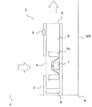
以下に本発明の第1の実施形態について図面を参照して説明する。図1は本実施形態のサーキュレータを示す側面断面図である。サーキュレータ1は、筐体2により本体部が保持されており、筐体2には湿度センサー3が設けられている。湿度センサー3は、サーキュレータ1の筐体2の外部の空気と触れるように設置されており、サーキュレータ1の近傍の空気の湿度を検知することができる。筐体2の内部には、吸込口4から吹出口5に連通する送風経路6が形成されている。送風経路6内には空気を送出する送風機7が配されている。送風機7に用いられるファンは、シロッコファン7bが用いられる。また、送風機7の起動、停止、風量調節といった動作制御は、湿度センサー3の検知情報をもとに、制御部8にて行われている。なお、サーキュレータ1の吸込口4にフィルタ(不図示)を備えることもでき、この場合には、サーキュレータ1は空気清浄機として機能することになる。
<First Embodiment>
A first embodiment of the present invention will be described below with reference to the drawings. FIG. 1 is a side sectional view showing a circulator of this embodiment. The
制御部8からの命令により送風機7が起動してサーキュレータ1が駆動を開始すると、サーキュレータ1前方の空気は吸込口4から吸い込まれ、送風経路6を流通して吹出口5から、サーキュレータ1の上方へ勢いよく送出される。これにより、部屋の空気を循環し、部屋の温度ムラを抑制するといった構成となっている。
When the
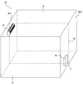
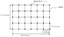
また、サーキュレータ1が設置されている部屋は、図2に示すように、天井面S、床面F、側壁W1、W2、W3、W4にて成る矩形の部屋Rであり、一般的な気密が確保されている。また、部屋Rをその中央鉛直面で2つに切った断面を断面Dとする。部屋Rの大きさは6畳(高さ2400mm、横3600mm、奥行き2700mm)である。また、後に断面Dの温度分布を示すが、その温度計測ポイントは、図3に示すように、断面Dにおいて、600mm間隔で高さ方向に5点、横方向に7点の、合計35点を計測した。
The room in which the
部屋Rの1つの側壁W1には、断面Dで左右に2分割されるように空気調和機9が設けられている。なお、一般的に、サーキュレータ1は、空気調和機9の設置される側壁W1と対向する側壁W2に設置されると効果的である旨が報告されており、本実施形態においては側壁W2と床Fにて囲まれたコーナー部に断面Dで左右に2分割されるようにサーキュレータ1を設置する。その時、前記湿度センサー3が配置される位置をポイントKとする。
On one side wall W1 of the room R, an
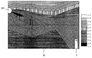
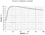
上記の部屋Rにおいて、冬季、気温5℃、相対湿度40%の状態から、サーキュレータ1が停止の状態で、従来の空気調和機9Aの暖房運転(設定温度26℃、暖房自動運転)を行った場合の部屋RのポイントKにおける気温と湿度の時間推移を計測した結果を図4、図5に示す。図4は、部屋RのポイントKにおける気温の時間推移を示し、横軸は経過時間、縦軸は気温を示している。また、図5は、部屋RのポイントKにおける気温の時間推移を示し、横軸は経過時間、縦軸は相対湿度を示している。また、図6は、空気調和機9Aの暖房運転開始から30分経過後の部屋Rの断面Dの温度分布を示しており、図7は、そのときの空気調和機9Aの暖房運転の気流の挙動の概略を示している。
In the room R described above, the heating operation (set
また、上記の部屋Rにおいて、冬季、気温5℃、相対湿度40%の状態から、サーキュレータ1が停止の状態で、特許文献5に記載の改良がなされた空気調和機9Bの暖房運転(設定温度26℃、暖房自動運転)を行った場合の部屋RのポイントKにおける気温と湿度の時間推移を計測した結果を図9、図10に示す。図9、図10における計測位置、横軸および縦軸は、図4、図5とそれぞれ同様である。また、図11は、空気調和機9Bの暖房運転開始から30分経過後の部屋Rの断面Dの温度分布を示しており、図12は、そのときの空気調和機9Bの暖房運転の気流の挙動の概略を示している。
Further, in the room R, the heating operation (set temperature) of the
上記より、空気調和機9Aおよび空気調和機9Bにおいて部屋Rを暖房運転した場合における、ポイントKの気温の推移(図4、図9)および湿度(図5、図10)はほぼ同一であるのに対し、暖房運転開始から30分経過後の部屋Rの断面Dの温度分布(図6、図11)は大きく異なっており、特に、天井面Sと床面Fの温度については、傾向が異なる。従来の空気調和機9Aの場合、天井面S近傍の温度>床面F近傍の温度となり、特許文献5に記載の、改良がなされた空気調和機9Bの場合、天井面S近傍の温度<床面F近傍の温度となっている。つまり、天井面Sと床面Fの温度や温度差においては、近年の空気調和機に関する研究開発の結果、従来の空気調和機の運転の場合と明らかに異なる傾向となる。
From the above, when the room R is heated in the
次に、上記の部屋Rにおいて、夏季、気温35℃、相対湿度60%の状態から、サーキュレータ1が停止の状態で、従来の空気調和機9Cの冷房運転(設定温度26℃、冷房自動運転)を行った場合の部屋RのポイントKにおける気温と湿度の時間推移を計測した結果を図14、図15に示す。図14、図15における計測位置、横軸および縦軸は、図4、図5とそれぞれ同様である。また、図16は、空気調和機9Cの冷房運転開始から30分経過後の部屋Rの断面Dの温度分布を示しており、図17は、そのときの空気調和機9Cの冷房運転の気流の挙動の概略を示している。
Next, in the room R described above, the cooling operation of the conventional air conditioner 9C (set
また、上記の部屋Rにおいて、夏季、気温35℃、相対湿度60%の状態から、サーキュレータ1が停止の状態で、特許文献4に記載の改良がなされた空気調和機9Dの冷房運転(設定温度26℃、冷房自動運転)を行った場合の部屋RのポイントKにおける気温と湿度の時間推移を計測した結果を図19、図20に示す。図19、図20における計測位置、横軸および縦軸は、図4、図5とそれぞれ同様である。また、図21は、空気調和機9Dの冷房運転開始から30分経過後の部屋Rの断面Dの温度分布を示しており、図22は、そのときの空気調和機9Dの冷房運転の気流の挙動の概略を示している。
Further, in the room R, the cooling operation (set temperature) of the
上記より、空気調和機9Cおよび空気調和機9Dにおいて部屋Rを冷房運転した場合における、ポイントKの気温の推移(図14、図19)および湿度(図15、図20)はほぼ同一であるのに対し、冷房運転開始から30分経過後の部屋Rの断面Dの温度分布(図16、図21)は大きく異なっており、特に、天井面Sと床面Fの温度については、傾向が異なる。従来の空気調和機9Cの場合、天井面S近傍の温度>床面F近傍の温度となり、特許文献4に記載の改良がなされた空気調和機9Dの場合、天井面S近傍の温度<床面F近傍の温度となっている。つまり、天井面Sと床面Fの温度や温度差においては、近年の空気調和機に関する研究開発の結果、従来の空気調和機の運転の場合と明らかに異なる傾向となる。
From the above, when the room R is air-cooled in the air conditioner 9C and the
上記、従来の空気調和機9Aおよび特許文献5に記載の改良がなされた空気調和機9Bによって部屋Rを暖房運転した場合の天井面Sと床面Fの温度や温度差の傾向の大きな違い、および、従来の空気調和機9Cおよび特許文献4に記載の改良がなされた空気調和機9Dによって部屋Rを冷房運転した場合の天井面Sと床面Fの温度や温度差の傾向の大きな違いから、天井面Sと床面Fの温度や温度差のみにてサーキュレータ1の起動のタイミングを判断するのは困難であることがわかる。
A large difference in the temperature and temperature difference between the ceiling surface S and the floor surface F when the room R is heated by the
それに対し、特に部屋Rの湿度の状況については、従来の空気調和機9Aおよび特許文献5に記載の改良がなされた空気調和機9Bによって部屋Rを暖房運転した場合においても、空気調和機9の設定温度が同じ場合、図5および図10のように、傾向が略同一となる。また、従来の空気調和機9Cおよび特許文献4に記載の改良がなされた空気調和機9Dによって部屋Rを冷房運転した場合においても、空気調和機9の設定温度が同じ場合、図15および図20のように、傾向が略同一となる。故に、湿度にてサーキュレータ1の起動のタイミングを判断すれば、上記のような空気調和機の違いによる差はなくなるか、または比較的小さくなるため、適切な起動が可能となる。
On the other hand, especially regarding the humidity condition of the room R, even when the room R is heated by the
本発明のサーキュレータ1は、この現象を利用し、サーキュレータ1の起動のタイミングを判断する。以下に、湿度にてサーキュレータ1の起動のタイミングを判断する方法について述べる。
The
先ず、暖房時において、図4、図5、および、図9、図10から、空気調和機9の運転開始とともに、部屋Rの室温(ポイントKの温度)は急激に上昇するとともに、それに伴い、部屋Rの相対湿度(ポイントKの相対湿度)は急激に低下する。本発明のサーキュレータ1においては、例えば、湿度センサー3にて1分で1%以上の相対湿度の低下を感知すると、制御部8が送風機7を起動させ、サーキュレータ1の駆動が開始されるように制御動作を行う。
First, during heating, from FIG. 4, FIG. 5, FIG. 9, and FIG. 10, as the operation of the
次に、冷房時において、図14、図15、および、図19、図20から、空気調和機9の運転開始とともに、部屋Rの室温(ポイントKの温度)は急激に低下するとともに、それに伴い、部屋Rの相対湿度(ポイントKの相対湿度)は急激に上昇する。本発明のサーキュレータ1においては、例えば、湿度センサー3にて1分で1%以上の相対湿度の上昇を感知すると、制御部8が送風機7を起動させ、サーキュレータ1の駆動が開始されるように制御動作を行う。
Next, during cooling, from FIG. 14, FIG. 15, FIG. 19, and FIG. 20, as the operation of the
このようにすることにより、空気調和機の違いによる天井面や床面の温度や温度差に依存することなく、適切な起動が可能となり、サーキュレータ1の効果を常に十分に得ることができ、より確実に省エネ効果を得ることができる。
By doing in this way, it becomes possible to start appropriately without depending on the temperature or temperature difference of the ceiling surface or floor surface due to the difference of the air conditioner, and the effect of the
具体的には、従来の空気調和機9Aによって部屋Rを暖房運転した場合は、第1の実施形態によるサーキュレータ1の駆動制御を行った状態では、図6に示すように、30分経過後の部屋Rの断面Dの床面近傍と天井面近傍の温度差が6〜7℃であったのが、第1の実施形態によるサーキュレータ1の駆動制御を行った状態では、図8に示すように、3〜4℃にまで緩和される。また、特許文献5に記載の改良がなされた空気調和機9Bによって部屋Rを暖房運転した場合は、サーキュレータ1の停止状態では、図11に示すように、30分経過後の部屋Rの断面Dの床面近傍と天井面近傍の温度差が5〜6℃であったのが、第1の実施形態によるサーキュレータ1の駆動制御を行った状態では、図13に示すように、3〜4℃にまで緩和される。また、従来の空気調和機9Cによって部屋Rを冷房運転した場合は、サーキュレータ1の停止状態では、図16に示すように、30分経過後の部屋Rの断面Dの床面近傍と天井面近傍の温度差が6〜7℃であったのが、サーキュレータ1の駆動状態では、図18に示すように、3〜4℃にまで緩和される。なお、特許文献5に記載の改良がなされた空気調和機9Dによって部屋Rを暖房運転した場合は、サーキュレータ1の停止状態(図11)でも第1の実施形態によるサーキュレータ1の駆動制御を行った状態(図23)でも、さほど効果を得ることはできない。
Specifically, when the room R is heated by the
また、例えば、部屋が大型であったり、形状が矩形ではなくてL字型や縦方向と横方向の寸法が大きく異なる、いわゆる縦長や横長の部屋、または、天井が非常に高いといった、変則的な形状である場合においては、部屋Rの天井面や床面の温度は場所によるバラツキが顕著になるが、部屋Rの相対湿度の場所によるバラツキは比較的小さくなるため、従来の天井面や床面の温度や温度差に依存する制御に比べ、相対湿度による制御の方が、より適切な起動が可能となり、サーキュレータ1の効果を常に十分に得ることができ、より確実に省エネ効果を得ることができる。
In addition, for example, the room is large, the shape is not rectangular, and the shape is L-shaped, the vertical and horizontal dimensions differ greatly, so-called vertical or horizontal rooms, or the ceiling is very high. In the case of a simple shape, the temperature of the ceiling surface and floor surface of the room R varies significantly depending on the location, but the variation due to the location of the relative humidity of the room R is relatively small. Compared to control that depends on surface temperature and temperature difference, control by relative humidity enables more appropriate startup, and the effect of the
具体的には、図24のようなL字型の部屋R'において、突き出した波線の領域の奥壁面に対向する広い壁面の、前記奥壁面を斜めに見る方の端部に、従来の空気調和機9Aを設けて、空気調和機9Aによって暖房運転する場合を考える。この場合、破線の領域の空気調和か極めて困難である。よって、図24のように前記奥壁面の空気調和機9Aから遠い方の端部に、サーキュレータ1を設置して破線の領域にまで空気調和が可能にしたい。しかし、空気調和機9Aを駆動しても、破線の領域は天井と床面に温度差が生じにくいため、従来の方法ではサーキュレータ1の駆動が開始されない。しかし、第1の実施形態の場合、サーキュレータ1の位置における湿度は変化するため、適切にサーキュレータ1を駆動できる。サーキュレータが駆動できない場合、図25(b)のように、L字型の部屋R'において、暖房時の床上600mm水平面における温度分布は、部屋R'の中央部と突き出した波線の領域との温度差が6〜7℃であったのが、サーキュレータ1が駆動できない場合、同図(a)のように、3〜4℃にまで緩和される。
Specifically, in an L-shaped room R ′ as shown in FIG. 24, conventional air is applied to the end of the wide wall facing the rear wall surface of the protruding wavy region at an angle when the rear wall surface is viewed obliquely. Consider a case in which a
なお、温度の拡散に対し、湿度の拡散は非常に早く、故に、部屋に大きな温度ムラが形成されていても、湿度はそれを乗り越えて拡散するため、湿度によりサーキュレータの運転開始を判断することにより、温度のみにてサーキュレータの運転開始を判断する場合に比べ、より迅速、適切にサーキュレータの運転を開始することができ、サーキュレータの運転が不必要にもかかわらず無駄に運転したり、また逆に、サーキュレータの運転が必要にも拘らずなかなか運転が開始されなかったりといった不具合の発生を抑制することができるため、確実に省エネ効果を得ることができる。 It should be noted that the diffusion of humidity is very fast compared to the diffusion of temperature, so even if large temperature irregularities are formed in the room, the humidity will spread over it, so the start of circulator operation should be judged by humidity. This makes it possible to start the circulator more quickly and appropriately than when judging the start of the circulator based only on the temperature. In addition, since it is possible to suppress the occurrence of problems such as the operation not starting easily even though the circulator is required to operate, an energy saving effect can be obtained with certainty.
第1の実施形態の方式と従来(床面温度と天井面温度の差にて駆動を開始する)の方式の違いによる、サーキュレータの適切な動作開始の度合は表1のようになる。 Table 1 shows the appropriate degree of start of the operation of the circulator depending on the difference between the method of the first embodiment and the conventional method (starting driving based on the difference between the floor surface temperature and the ceiling surface temperature).

本発明の効果をまとめると、以下のようになる。即ち本発明は、対象空間の空気流れを起こすファンと、前記ファンの作動を制御する制御部と、を備え、対象空間の温度ムラを減少させるためのサーキュレータにおいて、対象空間の空気の湿度を検知する湿度センサーを備え、あらかじめ設定した時間の間にあらかじめ設定した幅の湿度の変化が生じた場合に、前記制御部は前記ファンの運転を開始することを特徴としている。 The effects of the present invention are summarized as follows. That is, the present invention includes a fan that causes an air flow in the target space and a control unit that controls the operation of the fan, and detects the humidity of the air in the target space in a circulator for reducing temperature unevenness in the target space. The controller is configured to start the operation of the fan when a change in humidity of a preset width occurs during a preset time.
ある程度の気密が保たれている部屋において空気調和機が運転された場合、部屋の空気の湿度は急激に変動することが知られている。例えば冷房運転が開始された場合、部屋の温度は急激に低下する。しかしながら、部屋の絶対湿度は大きく変動しない。故に、部屋の相対湿度は大きく上昇する。例えば暖房運転が開始された場合、部屋の温度は急激に上昇する。しかしながら、部屋の絶対湿度は大きく変動しない。故に、部屋の相対湿度は大きく低下する。これらは、空気調和機に上記のような温度ムラが大幅に緩和されるような機能的、構造的な改良がなされていても、また、部屋の形状が大型であったり変則的な形状であったりした場合においても、部屋の気密がある程度保たれている場合には必ず言える現象である。 It is known that when the air conditioner is operated in a room where a certain degree of airtightness is maintained, the humidity of the air in the room fluctuates rapidly. For example, when the cooling operation is started, the room temperature rapidly decreases. However, the absolute humidity of the room does not vary greatly. Therefore, the relative humidity of the room is greatly increased. For example, when the heating operation is started, the temperature of the room rapidly increases. However, the absolute humidity of the room does not vary greatly. Therefore, the relative humidity of the room is greatly reduced. Even if the air conditioner has been functionally and structurally improved so that the above-mentioned temperature unevenness is greatly reduced, the room shape is large or irregular. This is a phenomenon that can be said when the room is kept airtight to some extent.
本発明によると、部屋においてあらかじめ設定した幅の湿度の変化が生じた場合に前記制御部は前記ファンの運転を開始するので、冷房運転が開始されるか、または、暖房運転が開始されるかした場合に生ずる湿度の大きな変化を検知し、サーキュレータの運転が開始される。これにより、従来想定し得ないような温度分布を生ずるような場合、例えば、空気調和機に上記のような温度ムラが大幅に緩和されるような機能的、構造的な改良がなされている場合、または、部屋の形状が大型であったり変則的な形状であったりした場合においても、確実に空気調和機の運転を検知することができ、適切にサーキュレータの運転を開始することができるため、確実に省エネ効果を得ることができる。 According to the present invention, when the humidity change of a preset width occurs in the room, the control unit starts the operation of the fan, so whether the cooling operation is started or the heating operation is started. When a large change in humidity is detected, the operation of the circulator is started. As a result, when a temperature distribution that cannot be assumed in the past is generated, for example, when functional and structural improvements are made such that the above-described temperature unevenness is greatly reduced in the air conditioner Or, even when the shape of the room is large or an irregular shape, the operation of the air conditioner can be reliably detected and the operation of the circulator can be started appropriately, An energy saving effect can be obtained with certainty.
上記実施形態においては、相対湿度の変化率によって、サーキュレータの運転開始を制御している。しかしながら、図5、図10、図15、図20から明らかなように、暖房運転時の相対湿度は、運転開始直後に15%を切り、冷房運転時の相対湿度は運転開始直後にほぼ100%になる。従って、気候、時間などによる変化はあるものの、基本的に、暖房時で相対湿度15%、冷房時で相対湿度95%を設定しておけば、空気調和機の運転をほぼ確実に検知することが可能である。従って、相対湿度の所定の値を検知することによっても、サーキュレータの運転開始を制御することが出来る。この場合において、より精度を高めるために、地域、気候、時間など、サーキュレータの設置場所に応じて運転開始時の相対湿度の値を決めればよい。 In the above embodiment, the operation start of the circulator is controlled by the rate of change of the relative humidity. However, as is apparent from FIGS. 5, 10, 15, and 20, the relative humidity during heating operation is less than 15% immediately after the start of operation, and the relative humidity during cooling operation is approximately 100% immediately after the start of operation. become. Therefore, although there is a change due to climate, time, etc., basically, if the relative humidity is set to 15% during heating and the relative humidity is set to 95% during cooling, the operation of the air conditioner can be detected almost certainly. Is possible. Therefore, the start of operation of the circulator can also be controlled by detecting a predetermined value of the relative humidity. In this case, in order to increase the accuracy, the relative humidity value at the start of operation may be determined according to the location of the circulator such as the area, climate, and time.
<第1の実施形態に係る他の実施形態>
次に、前記第1の実施形態に係る他の実施形態について説明する。本実施形態のサーキュレータ1は、第1の実施形態のサーキュレータ1に対し、湿度センサー3に替わり、相対湿度とともに気温も検知する温湿度センサー3b(不図示)にて成る構成となっている。その他の部分は第1の実施形態と同様である。
<Another embodiment according to the first embodiment>
Next, another embodiment according to the first embodiment will be described. The
本発明のサーキュレータ1においては、例えば、温湿度センサー3bにて1分で1℃以上の温度の上昇を感知するとともに、1分で1%以上の相対湿度の低下を感知するか、または、1分で1℃以上の温度の低下を感知するとともに、1分で1%以上の相対湿度の上昇を感知するか、のどちらかを感知した場合に、制御部8が送風機7を起動させ、サーキュレータ1の駆動が開始されるように制御動作を行う。
In the
本発明の効果をまとめると、以下のようになる。即ち本発明は、第1の実施形態のサーキュレータ1に対し、対象空間の空気の温度を検知する温度センサーをさらに備え、あらかじめ設定した時間の間にあらかじめ設定した幅の温度の変化とあらかじめ設定した幅の湿度の変化との両方が生じた場合に、前記制御部は前記ファンの運転を開始することを特徴としている。
The effects of the present invention are summarized as follows. That is, the present invention further includes a temperature sensor that detects the temperature of the air in the target space with respect to the
部屋の湿度は空気調和機の運転開始以外の際にも想定される。例えば気象が急激に変化した場合などが挙げられる。この構成によると、湿度と温度の両方の情報を得てサーキュレータの運転が開始されるため、例えば温暖前線の接近により急激に環境の湿度が上昇した場合のような場合と、空気調和機の運転が開始された場合が、区別される。 The humidity of the room is also assumed when the air conditioner is not started. For example, when the weather changes suddenly. According to this configuration, since the operation of the circulator is started by obtaining both humidity and temperature information, for example, when the humidity of the environment suddenly increases due to the approach of the warm front, and the operation of the air conditioner A distinction is made when the is started.
これにより、例えば気象が急激に変化した場合といった、空気調和機の運転開始以外の場合に生ずる部屋の湿度の変化と、空気調和機の運転に伴う部屋の湿度の変化とを区別することができ、適切にサーキュレータの運転を開始することができる。 This makes it possible to distinguish a change in room humidity that occurs when the air conditioner suddenly changes, such as when the weather changes suddenly, and a change in room humidity that accompanies the operation of the air conditioner. Can properly start the circulator operation.
<第2の実施形態>
次に、図26および図27は第2の実施形態のサーキュレータを示す側面断面図である。前述の図1および図2に示す第1の実施形態と同様の部分には同一の符号を付している。本実施形態のサーキュレータ1bは、第1の実施形態のサーキュレータ1に対し、以下の点で異なっている。先ず、送風機7の下流側において送風経路6が2分岐し、一方の送風経路6Aは上方へ延びて筐体2の天面に設けられた吹出口5Aに連通し、他方の送風経路6Bは下方へ延びて筐体2の前面下方に設けられた吹出口5Bに連通する。また、送風経路6Aおよび送風経路6Bには、ダンパー10A、10Bがそれぞれ設けられている。そして、図26に示すように、ダンパー10Aによって送風経路6Aが開放され、ダンパー10Bによって送風経路6Bが閉塞された場合には、吸込口4から吸込まれた空気は、吹出口5Aから部屋Rの上方(天井面S)(図26の矢印Aの方向)に向けて勢いよく送出される。また、図27に示すように、ダンパー10Aによって送風経路6Aが閉塞され、ダンパー10Bによって送風経路6Bが開放された場合には、吸込口4から吸込まれた空気は、吹出口5Bから部屋Rの下方(床面F)(図27の矢印Bの方向)に向けて勢いよく送出される。その他の部分は第1の実施形態と同様である。
<Second Embodiment>
Next, FIGS. 26 and 27 are side sectional views showing a circulator according to the second embodiment. The same parts as those in the first embodiment shown in FIGS. 1 and 2 are denoted by the same reference numerals. The
本実施形態のサーキュレータ1bにおいて、湿度センサー3にて1分で1%以上の相対湿度の低下を感知すると、制御部8は、ダンパー10Aを開放、ダンパー10Bを閉塞して送風機7を起動させ、サーキュレータ1の駆動が開始されるように制御動作を行う。
In the
また、湿度センサー3にて1分で1%以上の相対湿度の上昇を感知すると、制御部8は、ダンパー10Aを閉塞、ダンパー10Bを開放して送風機7を起動させ、サーキュレータ1の駆動が開始されるように制御動作を行う。
When the
このようにすることにより、湿度の急激な低下を感知した場合、吹出口5Aから部屋Rの上方(天井面S)に向けて勢いよく送出される。上述の通り、湿度の急激な低下を感知した場合、部屋Rは空気調和機9により暖房運転が開始されているので、部屋Rの床面F近傍の空気を天井面S近傍へと送り込んでやることにより、部屋Rの温度ムラを軽減することができる。また、湿度の急激な上昇を感知した場合、吹出口5Bから部屋Rの下方(床面F)に向けて勢いよく送出される。上述の通り、湿度の急激な上昇を感知した場合、部屋Rは空気調和機9により冷房運転が開始されているので、部屋Rの天井面S近傍の空気を床面F近傍へと送り込んでやることにより、部屋Rの温度ムラを軽減することができる。即ち、湿度の急激な低下または湿度の急激な上昇によって現在部屋Rが暖房されているのか冷房されているのかを判断し、それに対応して適切な風向の流れを部屋Rに作ることができるため、よりサーキュレータの温度ムラの軽減効果を得ることができる。
By doing in this way, when the sudden fall of humidity is detected, it sends out vigorously toward the upper direction (ceiling surface S) of room R from
本発明の効果をまとめると、以下のようになる。即ち本発明は、上記構成のサーキュレータにおいて、あらかじめ設定した時間の間にあらかじめ設定した幅の湿度の低下が生じた場合に、サーキュレータが設置されている位置を基準として、対象空間の上方から下方に空気流れを起こすように前記ファンを駆動することを特徴としている。この構成によると、空気調和機の暖房運転が開始された場合、湿度の大幅な低下を検知し、対象空間の上方から下方に空気流れを起こすようにサーキュレータの運転が行われるので、空気調和機の暖房運転に適切なサーキュレータの運転を行うことができ、確実に省エネ効果を得ることができる。 The effects of the present invention are summarized as follows. That is, according to the present invention, in the circulator having the above-described configuration, when a decrease in humidity of a preset width occurs during a preset time, the position where the circulator is installed is used as a reference from the upper side to the lower side of the target space. The fan is driven to generate an air flow. According to this configuration, when the heating operation of the air conditioner is started, the circulator is operated so as to detect a significant decrease in humidity and generate an air flow downward from above the target space. The circulator suitable for the heating operation can be operated, and an energy saving effect can be obtained with certainty.
また本発明は、上記構成のサーキュレータにおいて、あらかじめ設定した時間の間にあらかじめ設定した幅の湿度の上昇が生じた場合に、サーキュレータが設置されている位置を基準として、対象空間の下方から上方に空気流れを起こすように前記ファンを駆動することを特徴としている。この構成によると、空気調和機の冷房運転が開始された場合、湿度の大幅な上昇を検知し、対象空間の下方から上方に空気流れを起こすようにサーキュレータの運転が行われるので、空気調和機の冷房運転に適切なサーキュレータの運転を行うことができ、確実に省エネ効果を得ることができる。 Further, according to the present invention, in the circulator configured as described above, when a humidity increase of a preset width occurs during a preset time, the position where the circulator is installed is used as a reference from the lower side to the upper side of the target space. The fan is driven to generate an air flow. According to this configuration, when the cooling operation of the air conditioner is started, a significant increase in humidity is detected, and the circulator is operated so as to generate an air flow upward from below the target space. Therefore, it is possible to operate the circulator suitable for the cooling operation, and to surely obtain the energy saving effect.
<第2の実施形態に係る他の実施形態>
次に、前記第2の実施形態に係る他の実施形態について説明する。本実施形態のサーキュレータ1bは、第2の実施形態のサーキュレータ1bに対し、湿度センサー3に替わり、相対湿度とともに気温も検知する温湿度センサー3b(不図示)にて成る構成となっている。その他の部分は第2の実施形態と同様である。
<Another embodiment according to the second embodiment>
Next, another embodiment according to the second embodiment will be described. The
本発明のサーキュレータ1bにおいて、温湿度センサー3bにて1分で1℃以上の温度の上昇を感知するとともに、1分で1%以上の相対湿度の低下を感知すると、制御部8は、ダンパー10Aを開放、ダンパー10Bを閉塞して送風機7を起動させ、サーキュレータ1の駆動が開始されるように制御動作を行う。
In the
また、温湿度センサー3bにて1分で1℃以上の温度の低下を感知するとともに、1分で1%以上の相対湿度の上昇を感知すると、制御部8は、ダンパー10Aを閉塞、ダンパー10Bを開放して送風機7を起動させ、サーキュレータ1の駆動が開始されるように制御動作を行う。
Further, when the temperature /
このようにすることにより、温度の急激な上昇と湿度の急激な低下を同時に感知した場合、吹出口5Aから部屋Rの上方(天井面S)に向けて勢いよく送出される。上述の通り、温度の急激な上昇と湿度の急激な低下を同時に感知した場合、部屋Rは空気調和機9により暖房運転が開始されているので、部屋Rの床面F近傍の空気を天井面S近傍へと送り込んでやることにより、部屋Rの温度ムラを軽減することができる。また、温度の急激な低下と湿度の急激な上昇を同時に感知した場合、吹出口5Bから部屋Rの下方(床面F)に向けて勢いよく送出される。上述の通り、温度の急激な低下と湿度の急激な上昇を同時に感知した場合、部屋Rは空気調和機9により冷房運転が開始されているので、部屋Rの天井面S近傍の空気を床面F近傍へと送り込んでやることにより、部屋Rの温度ムラを軽減することができる。即ち、温度の急激な上昇と湿度の急激な低下、または、温度の急激な低下と湿度の急激な上昇、のどちらかによって現在部屋Rが暖房されているのか冷房されているのかを判断し、それに対応して適切な風向の流れを部屋Rに作ることができるため、サーキュレータの温度ムラの軽減効果をより適切に得ることができる。
By doing in this way, when a rapid increase in temperature and a rapid decrease in humidity are sensed simultaneously, the air is sent out vigorously from the
本発明の効果をまとめると、以下のようになる。即ち本発明は、第2の実施形態のサーキュレータ1bに対し、対象空間の空気の温度を検知する温度センサーをさらに備え、あらかじめ設定した時間の間にあらかじめ設定した幅の温度の上昇とあらかじめ設定した幅の湿度の低下との両方が生じた場合に、サーキュレータが設置されている位置を基準として、対象空間の上方から下方に空気流れを起こすように前記ファンを駆動することを特徴としている。この構成によると、空気調和機の暖房運転が開始された場合、温度の大幅な上昇と湿度の大幅な低下を検知し、対象空間の上方から下方に空気流れを起こすようにサーキュレータの運転が行われるので、空気調和機の暖房運転に適切なサーキュレータの運転を行うことができ、確実に省エネ効果を得ることができる。
The effects of the present invention are summarized as follows. That is, the present invention further includes a temperature sensor for detecting the temperature of the air in the target space with respect to the
また本発明は、上記構成のサーキュレータにおいて、あらかじめ設定した時間の間にあらかじめ設定した幅の温度の低下とあらかじめ設定した幅の湿度の上昇との両方が生じた場合に、サーキュレータが設置されている位置を基準として、対象空間の下方から上方に空気流れを起こすように前記ファンを駆動することを特徴としている。この構成によると、空気調和機の冷房運転が開始された場合、温度の大幅な低下と湿度の大幅な上昇を検知し、対象空間の下方から上方に空気流れを起こすようにサーキュレータの運転が行われるので、空気調和機の冷房運転に適切なサーキュレータの運転を行うことができ、確実に省エネ効果を得ることができる。 Further, according to the present invention, in the circulator configured as described above, a circulator is installed when both a decrease in temperature of a preset width and an increase in humidity of a preset width occur during a preset time. Based on the position, the fan is driven so as to generate an air flow from the lower side to the upper side of the target space. According to this configuration, when the cooling operation of the air conditioner is started, a significant decrease in temperature and a significant increase in humidity are detected, and the circulator is operated so that air flows upward from below the target space. Therefore, the operation of the circulator suitable for the cooling operation of the air conditioner can be performed, and the energy saving effect can be surely obtained.
<第3の実施形態>
次に、図28は第3の実施形態のサーキュレータを示す側面断面図である。前述の図1および図2に示す第1の実施形態と同様の部分には同一の符号を付している。本実施形態のサーキュレータ1cは、第1の実施形態のサーキュレータ1に対し、以下の点で異なっている。先ず、送風機7は、正方向と逆方向とどちらにも回転可能な可逆ファン7cを備えている。可逆ファン7cが正方向に回転する場合には、図中の矢印Aの方向、即ち、室内の空気は吸込口4から吸込まれ、吹出口5から部屋Rの上方(天井面S)に向けて勢いよく送出される。また、可逆ファン7cが逆方向に回転する場合には、図中の矢印Bの方向、即ち、室内の空気は、逆に、吹出口5から吸込まれ、吸込口4から部屋Rの下方(床面F)に向けて勢いよく送出される。また、湿度センサー3に替わり、相対湿度とともに気温も検知する温湿度センサー3bを備えるとともに、さらに、部屋Rの天井面Sと床面Fの温度を検知することができる温度センサー11を備えている。温度センサー11については、赤外線センサー、画像認識による温度センサー等、適宜用いることができ、部屋Rの天井面Sと床面Fの温度を検知してもよく、天井面S近傍の空気温度と床面F近傍の空気温度と、を検知するものでもよく、また、天井面Sと床面Fの温度差を検知するものでもよく、また、天井面S近傍の空気温度と床面F近傍の空気温度との温度差を検知するものでもよい。その他の部分は第1の実施形態と同様である。
<Third Embodiment>
Next, FIG. 28 is a side sectional view showing the circulator of the third embodiment. The same parts as those in the first embodiment shown in FIGS. 1 and 2 are denoted by the same reference numerals. The circulator 1c of this embodiment differs from the
本発明のサーキュレータ1cにおいて、温湿度センサー3bにて1分で1℃以上の温度の上昇を感知するとともに、1分で1%以上の相対湿度の低下を感知するか、または、温度センサー11にて、部屋Rの天井面Sと床面Fの温度差が10℃以上になっていることを感知するとともに、湿度が30%以下になっていることを温湿度センサー3bにて感知した場合に、制御部8は、可逆ファン7cが正方向に回転するように送風機7を起動させ、サーキュレータ1cの駆動が開始されるように制御動作を行う。
In the circulator 1c of the present invention, the temperature /
また、温湿度センサー3bにて1分で1℃以上の温度の低下を感知するとともに、1分で1%以上の相対湿度の上昇を感知するか、または、温度センサー11にて、部屋Rの天井面Sと床面Fの温度差が10℃以上になっていることを感知するとともに、湿度が60%以上になっていることを温湿度センサー3bにて感知した場合に、制御部8は、可逆ファン7cが逆方向に回転するように送風機7を起動させ、サーキュレータ1cの駆動が開始されるように制御動作を行う。
Further, the temperature /
このようにすることにより、温度の急激な上昇と湿度の急激な低下を同時に感知した場合、または、部屋Rの天井面Sと床面Fの温度に大きな差が生じたことを感知するとともに部屋の相対湿度があらかじめ設定された相対湿度よりも低下していることを感知した場合、吸込口4から吸込んだ空気を吹出口5から部屋Rの上方(天井面S)に向けて図28の矢印Aの方向に勢いよく送出される。上述の通り、温度の急激な上昇と湿度の急激な低下を同時に感知した場合、または、部屋Rの天井面Sと床面Fの温度に大きな差が生ずるとともに部屋の相対湿度があらかじめ設定された相対湿度よりも低下している場合、部屋Rは空気調和機9により暖房運転が開始されているので、部屋Rの床面F近傍の空気を天井面S近傍へと送り込んでやることにより、部屋Rの温度ムラを軽減することができる。
In this way, when a rapid increase in temperature and a rapid decrease in humidity are sensed at the same time, or a large difference between the temperature of the ceiling surface S and the floor surface F of the room R is detected and the room When the relative humidity of the air is sensed to be lower than the preset relative humidity, the air sucked from the
また、温度の急激な低下と湿度の急激な上昇を同時に感知した場合、または、部屋Rの天井面Sと床面Fの温度に大きな差が生じたことを感知するとともに部屋の相対湿度があらかじめ設定された相対湿度よりも上昇していることを感知した場合、吹出口5から吸込んだ空気を吸込口4から部屋Rの下方(床面F)に向けて図28の矢印Bの方向に勢いよく送出される。上述の通り、温度の急激な低下と湿度の急激な上昇を同時に感知した場合、または、部屋Rの天井面Sと床面Fの温度に大きな差が生ずるとともに部屋の相対湿度があらかじめ設定された相対湿度よりも上昇している場合、部屋Rは空気調和機9により冷房運転が開始されているので、部屋Rの天井面S近傍の空気を床面F近傍へと送り込んでやることにより、部屋Rの温度ムラを軽減することができる。
In addition, when a rapid decrease in temperature and a rapid increase in humidity are detected at the same time, or when a large difference has occurred in the temperature between the ceiling surface S and the floor surface F of the room R, the relative humidity of the room is set in advance. When it is sensed that the relative humidity is higher than the set relative humidity, the air sucked from the
即ち、温度の急激な上昇と湿度の急激な低下、または、温度の急激な低下と湿度の急激な上昇、または、部屋Rの天井面Sと床面Fの温度に大きな差が生じた場合の部屋の相対湿度、のいずれかによって現在部屋Rが暖房されているのか冷房されているのかを判断し、それに対応して適切な風向の流れを部屋Rに作ることができるため、よりサーキュレータの温度ムラの軽減効果を得ることができる。 That is, when there is a large difference between the temperature of the ceiling surface S and the floor surface F of the room R, or a rapid increase in temperature and a rapid decrease in humidity, or a rapid decrease in temperature and a rapid increase in humidity. It is possible to determine whether the room R is currently heated or cooled according to any of the relative humidity of the room, and accordingly, a flow of an appropriate wind direction can be created in the room R. Accordingly, the temperature of the circulator can be increased. The effect of reducing unevenness can be obtained.
本発明の効果をまとめると、以下のようになる。即ち本発明は、上記構成のサーキュレータにおいて、室内の天井もしくは天井近傍を含む点と、室内の床もしくは床面近傍を含む点の2点の温度差が、あらかじめ設定した温度差以上になるとともに、部屋の湿度とあらかじめ設定した湿度との大小比較により、前記制御部は前記ファンの運転を開始することを特徴としている。この構成によると、部屋の天井もしくは天井近傍と床もしくは床面近傍の温度に大きな差が生じたことを感知するとともに部屋の相対湿度があらかじめ設定された相対湿度よりも低下していることを感知した場合、または、部屋の天井と床面の温度に大きな差が生じたことを感知するとともに部屋の相対湿度があらかじめ設定された相対湿度よりも上昇していることを感知した場合に、前記制御部は前記ファンの運転を開始するので、冷房運転が開始されるか、または、暖房運転が開始されるかした場合に生ずる部屋の天井もしくは天井近傍と床もしくは床面近傍との温度差と、そのときの部屋の相対湿度の両方を検知し、サーキュレータの運転が開始されるので、部屋の天井もしくは天井近傍と床もしくは床面近傍の温度差のみに頼ったサーキュレータの起動の場合に比べ、より確実に空気調和機の運転を検知することができ、適切にサーキュレータの運転を開始することができるため、確実に省エネ効果を得ることができる。 The effects of the present invention are summarized as follows. That is, in the circulator having the above-described configuration, the temperature difference between the point including the indoor ceiling or the vicinity of the ceiling and the point including the indoor floor or the vicinity of the floor surface is not less than a preset temperature difference, The control unit starts the operation of the fan by comparing the humidity of the room with a preset humidity. According to this configuration, it senses that there is a large difference in temperature between the ceiling of the room or near the ceiling and the floor or near the floor, and senses that the relative humidity of the room is lower than the preset relative humidity. Or when it is detected that there is a large difference between the temperature of the ceiling and floor of the room and the relative humidity of the room is higher than a preset relative humidity. Since the part starts the operation of the fan, the temperature difference between the ceiling of the room or the vicinity of the ceiling and the floor or the vicinity of the floor surface when the cooling operation is started or the heating operation is started, Since both the relative humidity of the room at that time is detected and the circulator starts to operate, it depends only on the temperature difference between the ceiling of the room or near the ceiling and the floor or near the floor. Than in the case of activation of the calculator, can be more reliably detect the operation of the air conditioner, it is possible to start the operation of the appropriate circulator, can be obtained reliably energy saving effect.
<第3の実施形態に係る他の実施形態>
次に、前記第3の実施形態に係る他の実施形態について説明する。本実施形態のサーキュレータ1cは、第3の実施形態のサーキュレータ1cに対し、温湿度センサー3bおよび温度センサー11が廃止され、それに変わり第1の実施形態と同様の湿度センサー3が設けられる。また、制御部8は、現在の時期を判断する手段としてカレンダー機能を備えており、現時点の日付や時刻や季節が把握できるとともに、当該地域の気候による平均的な湿度を判断するデータベースとして、例えば国内の各地域の月・時間別の過去の気象データ(温度・湿度)を備えている。その他の部分は第3の実施形態と同様である。
<Another embodiment according to the third embodiment>
Next, another embodiment according to the third embodiment will be described. The circulator 1c according to this embodiment is different from the circulator 1c according to the third embodiment in that the temperature /
本発明のサーキュレータ1cにおいては、使用の前に先ずサーキュレータ1cを設置する地域と現在の日時を設定することが望ましい。これは、使用する地域を想定して工場出荷時にあらかじめ設定しておいても良いし、また、使用者により設定できるようにしても良い。 In the circulator 1c of the present invention, it is desirable to first set the area where the circulator 1c is installed and the current date and time before use. This may be set in advance at the time of factory shipment assuming the area to be used, or may be set by the user.
本実施形態において、例えば使用地を「本州太平洋側地域」と設定した場合には、7月、8月、9月に、湿度センサー3にて相対湿度が90%以上になったことを感知すると、制御部8は、可逆ファン7cが正方向に回転するように送風機7を起動させ、サーキュレータ1cの駆動が開始されるように制御動作を行う。また、12月、1月、2月に、湿度センサー3にて相対湿度が15%以下になったことを感知すると、制御部8は、可逆ファン7cが逆方向に回転するように送風機7を起動させ、サーキュレータ1cの駆動が開始されるように制御動作を行う。
In this embodiment, for example, when the place of use is set as “Honshu Pacific side”, when the
本実施形態において、例えば使用地を「本州日本海側地域」と設定した場合には、7月、8月、9月に、湿度センサー3にて相対湿度が80%以上になったことを感知すると、制御部8は、可逆ファン7cが正方向に回転するように送風機7を起動させ、サーキュレータ1cの駆動が開始されるように制御動作を行う。また、12月、1月、2月に、湿度センサー3にて相対湿度が40%以下になったことを感知すると、制御部8は、可逆ファン7cが逆方向に回転するように送風機7を起動させ、サーキュレータ1cの駆動が開始されるように制御動作を行う。
In this embodiment, for example, when the place of use is set as “Honshu-Japan Sea side area”, the
上記の地域とあらかじめ設定される湿度の関係は、地域別の過去の気象データから、
夏季においては、例えば、{過去の平均湿度+(過去の最高湿度−過去の平均湿度)/2}の値を、冬季においては、例えば、{過去の平均湿度−(過去の平均湿度−過去の最低湿度)/2}の値を、それぞれ設定する方法が簡便である。より望ましくは、空気調和機を駆動しない場合には到達しないが空気調和機を駆動すると到達する相対湿度の値を採用すればより確実である。
The relationship between the above areas and the preset humidity is based on past weather data by area.
In the summer, for example, the value of {past average humidity + (past maximum humidity−past average humidity) / 2} is used, and in the winter, for example, {past average humidity− (past average humidity−past average humidity−past The method of setting each value of (minimum humidity) / 2} is simple. More desirably, the value is not reached when the air conditioner is not driven, but it is more reliable if the relative humidity value reached when the air conditioner is driven is adopted.
このようにすることにより、より簡単な構成で上記第3の実施形態と略同様の効果を得ることができる。 By doing in this way, the effect similar to the said 3rd Embodiment can be acquired with a simpler structure.
本発明の効果をまとめると、以下のようになる。即ち本発明は、対象空間の空気流れを起こすファンと、前記ファンの作動を制御する制御部と、を備え、対象空間の温度ムラを減少させるためのサーキュレータにおいて、対象空間の空気の湿度を検知する湿度センサーと、現在の時期を判断する手段と、をさらに備え、あらかじめ設定した時期にあらかじめ設定した湿度になった場合に、前記制御部は前記ファンの運転を開始することを特徴としている。この構成によると、時期を判断する手段によりその時期が夏季か冬季かが判断され、部屋の相対湿度が、その季節に応じてあらかじめ設定された相対湿度に到達すると、サーキュレータの運転が行われるので、時期や季節に応じて空気調和機の運転を推測検知することができ、適切にサーキュレータの運転を開始することができるため、確実に省エネ効果を得ることができる。例えば夏季の場合にはあらかじめ設定した相対湿度(例えば90%)以上に部屋の相対湿度が上昇すればサーキュレータの運転が行われ、例えば冬季の場合にはあらかじめ設定した相対湿度(例えば15%)以下に部屋の相対湿度が低下すればサーキュレータの運転が行われる。あらかじめ設定される相対湿度の好適な設定値として好適な方法としては、このサーキュレータが用いられる地域別の過去の気象データから判断され、適宜好適な値が採用される。望ましくは、その時期において、空気調和機を駆動しない場合には到達しないが空気調和機を駆動すると到達する相対湿度を採用するとよい。 The effects of the present invention are summarized as follows. That is, the present invention includes a fan that causes an air flow in the target space and a control unit that controls the operation of the fan, and detects the humidity of the air in the target space in a circulator for reducing temperature unevenness in the target space. A humidity sensor for determining the current time, and when the humidity reaches a preset humidity at a preset time, the control unit starts operating the fan. According to this configuration, the means for determining the time determines whether the time is summer or winter, and the circulator is operated when the relative humidity of the room reaches a relative humidity set in advance according to the season. Since the operation of the air conditioner can be estimated and detected according to the time and season and the operation of the circulator can be started appropriately, an energy saving effect can be obtained with certainty. For example, in the summer season, the circulator is operated when the relative humidity of the room rises above a preset relative humidity (for example, 90%). For example, in the winter season, the relative humidity (for example, 15%) or less is set. If the relative humidity of the room decreases, the circulator is operated. As a preferable method for setting the relative humidity set in advance, it is determined from past weather data for each region where this circulator is used, and a suitable value is appropriately adopted. Desirably, the relative humidity that is reached when the air conditioner is driven but not reached when the air conditioner is not driven may be adopted at that time.
<第3の実施形態に係るさらに他の実施形態>
次に、前記第3の実施形態に係るさらに他の実施形態について説明する。本実施形態のサーキュレータ1cは、第3の実施形態に係る他のサーキュレータ1cに対し、湿度センサー3が廃止され、それに変わり部屋の絶対湿度と相対湿度を同時に検知できる湿度センサー3cが設けられる。その他の部分は第3の実施形態と同様である。
<Another embodiment according to the third embodiment>
Next, still another embodiment according to the third embodiment will be described. The circulator 1c according to the present embodiment is provided with a humidity sensor 3c that can simultaneously detect the absolute humidity and the relative humidity of the room instead of the other circulator 1c according to the third embodiment. Other parts are the same as those of the third embodiment.
本実施形態において、例えば使用地を「日本」と設定した場合には、部屋の空気の絶対湿度と相対湿度が検知され、それらの値から気温が算出される。例えば7月、8月、9月の日中に、絶対湿度と相対湿度から算出した気温が30度程度の場合には、空気調和機は動作していないと判断され、サーキュレータ1cの駆動は開始されない。例えば7月、8月、9月の日中に、絶対湿度と相対湿度から算出した気温が20度程度の場合には、空気調和機は動作していると判断され、制御部8は、可逆ファン7cが正方向に回転するように送風機7を起動させ、サーキュレータ1cの駆動が開始されるように制御動作を行う。例えば、12月、1月、2月に、絶対湿度と相対湿度から算出した気温が10度程度の場合には、空気調和機は動作していないと判断され、サーキュレータ1cの駆動は開始されない。例えば、12月、1月、2月に、絶対湿度と相対湿度から算出した気温が25度程度の場合には、空気調和機は動作していると判断され、制御部8は、可逆ファン7cが逆方向に回転するように送風機7を起動させ、サーキュレータ1cの駆動が開始されるように制御動作を行う。
In the present embodiment, for example, when the place of use is set to “Japan”, the absolute humidity and the relative humidity of the air in the room are detected, and the temperature is calculated from those values. For example, if the temperature calculated from the absolute humidity and the relative humidity is about 30 degrees during the day of July, August, and September, it is determined that the air conditioner is not operating, and the driving of the circulator 1c is started. Not. For example, during the day of July, August, and September, when the temperature calculated from the absolute humidity and the relative humidity is about 20 degrees, it is determined that the air conditioner is operating, and the
具体的には、例えば7月、8月、9月の日中において、絶対湿度が12g/kg、相対湿度が40%の場合、室温は32.2℃と算出され、その結果、空気調和機は動作していないと判断され、サーキュレータの運転は行われない。例えば7月、8月、9月の日中において、絶対湿度が12g/kg、相対湿度が90%の場合、室温は18.5℃と算出され、その結果、空気調和機が動作していると判断され、サーキュレータの運転が行われる。例えば12月、1月、2月の日中において、絶対湿度が5g/kg、相対湿度が60%の場合、室温は11.4℃と算出され、その結果、空気調和機は動作していないと判断され、サーキュレータの運転は行われない。例えば12月、1月、2月の日中において、絶対湿度が5g/kg、相対湿度が15%の場合、室温は34.2℃と算出され、その結果、空気調和機が動作していると判断され、サーキュレータの運転が行われる。 Specifically, for example, when the absolute humidity is 12 g / kg and the relative humidity is 40% during the day of July, August, and September, the room temperature is calculated as 32.2 ° C., and as a result, the air conditioner Is determined not to operate, and the circulator is not operated. For example, when the absolute humidity is 12 g / kg and the relative humidity is 90% during the day of July, August, and September, the room temperature is calculated to be 18.5 ° C. As a result, the air conditioner is operating. It is determined that the circulator is operated. For example, when the absolute humidity is 5 g / kg and the relative humidity is 60% during the day of December, January, and February, the room temperature is calculated as 11.4 ° C. As a result, the air conditioner is not operating. The circulator is not operated. For example, when the absolute humidity is 5 g / kg and the relative humidity is 15% during the day of December, January, and February, the room temperature is calculated to be 34.2 ° C, and as a result, the air conditioner is operating. It is determined that the circulator is operated.
例えば使用地を「オーストラリア」と設定した場合には、部屋の空気の絶対湿度と相対湿度が検知され、それらの値から気温が算出される。例えば12月、1月、2月の日中に、絶対湿度と相対湿度から算出した気温が30度程度の場合には、空気調和機は動作していないと判断され、サーキュレータ1cの駆動は開始されない。例えば12月、1月、2月の日中に、絶対湿度と相対湿度から算出した気温が20度程度の場合には、空気調和機は動作していると判断され、制御部8は、可逆ファン7cが正方向に回転するように送風機7を起動させ、サーキュレータ1cの駆動が開始されるように制御動作を行う。例えば、6月、7月、8月に、絶対湿度と相対湿度から算出した気温が10度程度の場合には、空気調和機は動作していないと判断され、サーキュレータ1cの駆動は開始されない。例えば、6月、7月、8月に、絶対湿度と相対湿度から算出した気温が25度程度の場合には、空気調和機は動作していると判断され、制御部8は、可逆ファン7cが逆方向に回転するように送風機7を起動させ、サーキュレータ1cの駆動が開始されるように制御動作を行う。
For example, when the place of use is set to “Australia”, the absolute humidity and relative humidity of the air in the room are detected, and the temperature is calculated from these values. For example, if the temperature calculated from the absolute humidity and the relative humidity is about 30 degrees during the day of December, January, and February, it is determined that the air conditioner is not operating, and the driving of the circulator 1c is started. Not. For example, if the temperature calculated from the absolute humidity and the relative humidity is about 20 degrees during the day of December, January, and February, the air conditioner is determined to be operating, and the
このようにすることにより、より簡単な構成で上記第3の実施形態と略同様の効果を得ることができる。 By doing in this way, the effect similar to the said 3rd Embodiment can be acquired with a simpler structure.
本発明の効果をまとめると、以下のようになる。即ち本発明は、また本発明は、対象空間の空気流れを起こすファンと、前記ファンの作動を制御する制御部と、を備え、対象空間の温度ムラを減少させるためのサーキュレータにおいて、対象空間の空気の絶対湿度と相対湿度の両方を検知する湿度センサーと、現在の時期を判断する手段と、をさらに備え、絶対湿度と相対湿度と現在の時期から判断して、前記制御部は前記ファンの運転を開始することを特徴としている。この構成によると、時期を判断する手段によりその時期が夏季か冬季かが判断され、部屋の絶対湿度と相対湿度から、気温が算出され、季節、時間帯、算出した気温から、サーキュレータの運転の必要性が判断され、必要な場合にはサーキュレータの運転が行われる。これにより、時期、季節、時間帯に応じて空気調和機の運転を推測検知することができ、適切にサーキュレータの運転を開始することができるため、確実に省エネ効果を得ることができる。 The effects of the present invention are summarized as follows. That is, the present invention is also a circulator for reducing temperature unevenness in a target space, including a fan that causes an air flow in the target space and a control unit that controls the operation of the fan. A humidity sensor that detects both the absolute humidity and the relative humidity of the air, and a means for determining the current time; and determining from the absolute humidity, the relative humidity, and the current time; It is characterized by starting operation. According to this configuration, the means for determining the time determines whether the time is summer or winter, and the temperature is calculated from the absolute humidity and relative humidity of the room. The necessity is judged, and the circulator is operated when necessary. As a result, the operation of the air conditioner can be estimated and detected according to the time, season, and time zone, and the operation of the circulator can be appropriately started, so that an energy saving effect can be reliably obtained.
以上により、本発明に係るサーキュレータを第1〜第3実施形態により説明したが、本発明は上記実施形態に限定される訳ではなく、本発明の趣旨を逸脱しない範囲で適宜の変更を加えて実施することができる。例えば、上記の実施形態においてサーキュレータの制御のために用いた相対湿度の変化率の感知に要する時間やパーセンテージ、及び温湿度の値は一例であり、状況に応じて適宜適当な値を選択することができることは言うまでもない。また、上記の実施形態で説明に用いたサーキュレータも一例であって、少なくともファンとファンの作動を制御する制御部とを備えた装置であれば、換気扇、扇風機、天井扇、空気清浄機、加湿器、除湿機、ファンヒータなど、空気調和機以外の室内空気を攪拌する機能を発揮しうるあらゆる装置に対して本発明の適用が可能である。 As described above, the circulator according to the present invention has been described with reference to the first to third embodiments. However, the present invention is not limited to the above-described embodiments, and appropriate modifications are made without departing from the spirit of the present invention. Can be implemented. For example, the time and percentage required for sensing the rate of change of relative humidity used for controlling the circulator in the above embodiment, and the value of temperature and humidity are examples, and appropriate values should be selected according to the situation. Needless to say, you can. Further, the circulator used in the description in the above embodiment is also an example, and if it is a device including at least a fan and a control unit for controlling the operation of the fan, a ventilation fan, a fan, a ceiling fan, an air cleaner, a humidifier The present invention can be applied to any device capable of exhibiting a function of stirring room air other than an air conditioner, such as an air conditioner, a dehumidifier, and a fan heater.
1 サーキュレータ
2 筐体
3 湿度センサー
3b 温湿度センサー
4 吸込口
5 吹出口
6 送風経路
7 送風機
7b シロッコファン
7c 可逆回転ファン
8 制御部
9 空気調和機
10 ダンパー
11 温度センサー
DESCRIPTION OF
Claims (4)
前記対象空間の空気の相対湿度を検知する湿度センサーを設け、当該検知相対湿度の値に基づいて前記ファンの作動を開始し、
前記検知相対湿度の値は、地域、時間、気候の少なくとも1つを変数として設定された値である、サーキュレータ。 A circulator having a heat source that forcibly changes the ambient temperature and detecting a start of the operation of an air conditioner that adjusts the temperature of the target space by its operation, and a fan that operates to reduce temperature unevenness in the target space In
The humidity sensor for detecting the relative humidity of the air in the target space is provided to initiate operation of the fan based on the value of the sensing relative humidity,
The value of the detected relative humidity is a circulator set with at least one of region, time, and climate as a variable .
前記対象空間の空気の湿度を検知する湿度センサーをさらに備え、あらかじめ設定した時間の間にあらかじめ設定した幅の湿度の変化が生じた場合に、前記制御部は前記ファンの運転を開始し、
前記あらかじめ設定した時間の間にあらかじめ設定した幅の湿度の低下が生じた場合に、自己が設置された位置を基準として前記対象空間の上方から下方に空気流れを起こすように前記ファンを駆動し、
前記あらかじめ設定した時間の間にあらかじめ設定した幅の湿度の上昇が生じた場合に、自己が設置された位置を基準として前記対象空間の下方から上方に空気流れを起こすように前記ファンを駆動する、サーキュレータ。 A circulator for reducing temperature unevenness in a target space, comprising a fan and a control unit for controlling the operation of the fan;
Wherein further comprising a humidity sensor for detecting the humidity of the air in the target space, if the change in the humidity of the preset width between the preset time has occurred, the control unit starts the operation of the fan,
The fan is driven so as to generate an air flow from the upper side to the lower side of the target space when a drop in humidity of a preset width occurs during the preset time, with reference to the position where it is installed. ,
The fan is driven so as to generate an air flow from the lower side to the upper side of the target space with respect to the position where the device is installed, when a humidity increase of a preset width occurs during the preset time. , Circulator.
前記対象空間の空気の湿度を検知する湿度センサーと、現在の時期を判断する手段と、をさらに備え、あらかじめ設定した時期にあらかじめ設定した湿度になった場合に、前記制御部は前記ファンの運転を開始する、サーキュレータ。 A circulator for reducing temperature unevenness in a target space, comprising a fan and a control unit for controlling the operation of the fan;
A humidity sensor for detecting the humidity of the air in the target space; and means for determining the current time, and when the humidity reaches a preset humidity at a preset time, the control unit operates the fan. To start the circulator.
Priority Applications (1)
| Application Number | Priority Date | Filing Date | Title |
|---|---|---|---|
| JP2008055702A JP5053128B2 (en) | 2008-03-06 | 2008-03-06 | Circulator |
Applications Claiming Priority (1)
| Application Number | Priority Date | Filing Date | Title |
|---|---|---|---|
| JP2008055702A JP5053128B2 (en) | 2008-03-06 | 2008-03-06 | Circulator |
Publications (3)
| Publication Number | Publication Date |
|---|---|
| JP2009210223A JP2009210223A (en) | 2009-09-17 |
| JP2009210223A5 JP2009210223A5 (en) | 2010-07-08 |
| JP5053128B2 true JP5053128B2 (en) | 2012-10-17 |
Family
ID=41183559
Family Applications (1)
| Application Number | Title | Priority Date | Filing Date |
|---|---|---|---|
| JP2008055702A Expired - Fee Related JP5053128B2 (en) | 2008-03-06 | 2008-03-06 | Circulator |
Country Status (1)
| Country | Link |
|---|---|
| JP (1) | JP5053128B2 (en) |
Families Citing this family (4)
| Publication number | Priority date | Publication date | Assignee | Title |
|---|---|---|---|---|
| JP2012063113A (en) * | 2010-09-17 | 2012-03-29 | Mitsubishi Heavy Ind Ltd | Air conditioner |
| JP5984964B2 (en) * | 2012-12-10 | 2016-09-06 | 三菱電機株式会社 | Air conditioning system |
| JP6253774B2 (en) * | 2014-06-09 | 2017-12-27 | 三菱電機株式会社 | Air conditioning system |
| JP6926830B2 (en) * | 2017-08-29 | 2021-08-25 | 株式会社富士通ゼネラル | Blower |
Family Cites Families (8)
| Publication number | Priority date | Publication date | Assignee | Title |
|---|---|---|---|---|
| JPH08270992A (en) * | 1995-03-31 | 1996-10-18 | Matsushita Electric Works Ltd | Circulator and temperature sensor thereof |
| JP2001041518A (en) * | 1999-07-29 | 2001-02-16 | Sanyo Electric Co Ltd | Air cleaner |
| JP2001235215A (en) * | 2000-02-21 | 2001-08-31 | Sanyo Electric Co Ltd | Controller for air conditioner |
| JP4701553B2 (en) * | 2001-07-19 | 2011-06-15 | ダイキン工業株式会社 | Condensation prevention device for windows |
| JP2004020072A (en) * | 2002-06-18 | 2004-01-22 | Fujitsu General Ltd | Control method of floor mounting type circulator |
| JP2004150679A (en) * | 2002-10-30 | 2004-05-27 | Sanyo Electric Co Ltd | Air-conditioning system |
| JP4572544B2 (en) * | 2004-02-16 | 2010-11-04 | ダイキン工業株式会社 | Circulator |
| JP3104900U (en) * | 2004-04-22 | 2004-10-21 | 株式会社星和電機 | Circulator |
-
2008
- 2008-03-06 JP JP2008055702A patent/JP5053128B2/en not_active Expired - Fee Related
Also Published As
| Publication number | Publication date |
|---|---|
| JP2009210223A (en) | 2009-09-17 |
Similar Documents
| Publication | Publication Date | Title |
|---|---|---|
| JP5535336B2 (en) | Ventilation air conditioner | |
| JP5250011B2 (en) | Air conditioner | |
| US8826678B2 (en) | Air conditioner | |
| KR100803112B1 (en) | Air conditioner | |
| JP6072561B2 (en) | Air conditioning system | |
| JP6253459B2 (en) | Ventilator for air conditioning | |
| JP6781395B2 (en) | Air conditioner | |
| JP5053128B2 (en) | Circulator | |
| JP5244411B2 (en) | Energy saving operation method of air conditioner and air conditioner | |
| JP2007155261A (en) | Air conditioner | |
| JP2016038135A (en) | Air conditioner | |
| WO2000022355A1 (en) | Air conditioner | |
| EP1319900A1 (en) | Air conditioner and method for controlling the same | |
| AU2003254916B2 (en) | Air conditioner and method of controlling air conditioner | |
| JP2012013261A (en) | Control device of circulator | |
| JP2007187334A (en) | Air conditioner | |
| JP7321283B2 (en) | Control devices, air conditioners and air conditioning systems | |
| JP6418147B2 (en) | air conditioner | |
| JP5750364B2 (en) | Air conditioner | |
| US10837670B2 (en) | Air-conditioning apparatus | |
| JP6431366B2 (en) | Air conditioning system | |
| JP2005061674A (en) | Indoor unit for air conditioner | |
| JP5797169B2 (en) | Air conditioner | |
| JP3525021B2 (en) | Air conditioner | |
| JP2015148371A (en) | Indoor unit of air conditioner |
Legal Events
| Date | Code | Title | Description |
|---|---|---|---|
| A521 | Written amendment |
Free format text: JAPANESE INTERMEDIATE CODE: A523 Effective date: 20100526 |
|
| A621 | Written request for application examination |
Free format text: JAPANESE INTERMEDIATE CODE: A621 Effective date: 20100526 |
|
| A977 | Report on retrieval |
Free format text: JAPANESE INTERMEDIATE CODE: A971007 Effective date: 20111028 |
|
| A131 | Notification of reasons for refusal |
Free format text: JAPANESE INTERMEDIATE CODE: A131 Effective date: 20111122 |
|
| A521 | Written amendment |
Free format text: JAPANESE INTERMEDIATE CODE: A523 Effective date: 20120117 |
|
| TRDD | Decision of grant or rejection written | ||
| A01 | Written decision to grant a patent or to grant a registration (utility model) |
Free format text: JAPANESE INTERMEDIATE CODE: A01 Effective date: 20120703 |
|
| A01 | Written decision to grant a patent or to grant a registration (utility model) |
Free format text: JAPANESE INTERMEDIATE CODE: A01 |
|
| A61 | First payment of annual fees (during grant procedure) |
Free format text: JAPANESE INTERMEDIATE CODE: A61 Effective date: 20120725 |
|
| R150 | Certificate of patent or registration of utility model |
Ref document number: 5053128 Country of ref document: JP Free format text: JAPANESE INTERMEDIATE CODE: R150 Free format text: JAPANESE INTERMEDIATE CODE: R150 |
|
| FPAY | Renewal fee payment (event date is renewal date of database) |
Free format text: PAYMENT UNTIL: 20150803 Year of fee payment: 3 |
|
| S531 | Written request for registration of change of domicile |
Free format text: JAPANESE INTERMEDIATE CODE: R313531 |
|
| LAPS | Cancellation because of no payment of annual fees | ||
| R350 | Written notification of registration of transfer |
Free format text: JAPANESE INTERMEDIATE CODE: R350 |