JP2008201671A - Lower-energy hydrogen method and structure - Google Patents
Lower-energy hydrogen method and structure Download PDFInfo
- Publication number
- JP2008201671A JP2008201671A JP2008078173A JP2008078173A JP2008201671A JP 2008201671 A JP2008201671 A JP 2008201671A JP 2008078173 A JP2008078173 A JP 2008078173A JP 2008078173 A JP2008078173 A JP 2008078173A JP 2008201671 A JP2008201671 A JP 2008201671A
- Authority
- JP
- Japan
- Prior art keywords
- hydrogen
- energy
- cell
- atoms
- source
- Prior art date
- Legal status (The legal status is an assumption and is not a legal conclusion. Google has not performed a legal analysis and makes no representation as to the accuracy of the status listed.)
- Pending
Links
Images


Classifications
-
- G—PHYSICS
- G21—NUCLEAR PHYSICS; NUCLEAR ENGINEERING
- G21B—FUSION REACTORS
- G21B3/00—Low temperature nuclear fusion reactors, e.g. alleged cold fusion reactors
-
- F—MECHANICAL ENGINEERING; LIGHTING; HEATING; WEAPONS; BLASTING
- F02—COMBUSTION ENGINES; HOT-GAS OR COMBUSTION-PRODUCT ENGINE PLANTS
- F02G—HOT GAS OR COMBUSTION-PRODUCT POSITIVE-DISPLACEMENT ENGINE PLANTS; USE OF WASTE HEAT OF COMBUSTION ENGINES; NOT OTHERWISE PROVIDED FOR
- F02G1/00—Hot gas positive-displacement engine plants
- F02G1/04—Hot gas positive-displacement engine plants of closed-cycle type
- F02G1/043—Hot gas positive-displacement engine plants of closed-cycle type the engine being operated by expansion and contraction of a mass of working gas which is heated and cooled in one of a plurality of constantly communicating expansible chambers, e.g. Stirling cycle type engines
-
- F—MECHANICAL ENGINEERING; LIGHTING; HEATING; WEAPONS; BLASTING
- F02—COMBUSTION ENGINES; HOT-GAS OR COMBUSTION-PRODUCT ENGINE PLANTS
- F02G—HOT GAS OR COMBUSTION-PRODUCT POSITIVE-DISPLACEMENT ENGINE PLANTS; USE OF WASTE HEAT OF COMBUSTION ENGINES; NOT OTHERWISE PROVIDED FOR
- F02G2243/00—Stirling type engines having closed regenerative thermodynamic cycles with flow controlled by volume changes
- F02G2243/30—Stirling type engines having closed regenerative thermodynamic cycles with flow controlled by volume changes having their pistons and displacers each in separate cylinders
- F02G2243/50—Stirling type engines having closed regenerative thermodynamic cycles with flow controlled by volume changes having their pistons and displacers each in separate cylinders having resonance tubes
- F02G2243/52—Stirling type engines having closed regenerative thermodynamic cycles with flow controlled by volume changes having their pistons and displacers each in separate cylinders having resonance tubes acoustic
-
- F—MECHANICAL ENGINEERING; LIGHTING; HEATING; WEAPONS; BLASTING
- F02—COMBUSTION ENGINES; HOT-GAS OR COMBUSTION-PRODUCT ENGINE PLANTS
- F02G—HOT GAS OR COMBUSTION-PRODUCT POSITIVE-DISPLACEMENT ENGINE PLANTS; USE OF WASTE HEAT OF COMBUSTION ENGINES; NOT OTHERWISE PROVIDED FOR
- F02G2254/00—Heat inputs
- F02G2254/10—Heat inputs by burners
- F02G2254/11—Catalytic burners
-
- Y—GENERAL TAGGING OF NEW TECHNOLOGICAL DEVELOPMENTS; GENERAL TAGGING OF CROSS-SECTIONAL TECHNOLOGIES SPANNING OVER SEVERAL SECTIONS OF THE IPC; TECHNICAL SUBJECTS COVERED BY FORMER USPC CROSS-REFERENCE ART COLLECTIONS [XRACs] AND DIGESTS
- Y02—TECHNOLOGIES OR APPLICATIONS FOR MITIGATION OR ADAPTATION AGAINST CLIMATE CHANGE
- Y02E—REDUCTION OF GREENHOUSE GAS [GHG] EMISSIONS, RELATED TO ENERGY GENERATION, TRANSMISSION OR DISTRIBUTION
- Y02E30/00—Energy generation of nuclear origin
- Y02E30/10—Nuclear fusion reactors
Abstract
Description
(発明の背景)
この発明は、水素原子(分子)からエネルギーを放出するための方法と装置に関する。その電子は、遷移触媒を供給することによって、より低エネルギー準位、および「基底状態」より小さい半径(より小さい半直径および半短径)まで緩和するよう誘導される。この遷移触媒は、エネルギーシンクとして、または放出された電子エネルギーと共鳴するエネルギーを取り除き、新しい原子モデルに従って、これらの遷移を誘導する方法として機能する。遷移触媒は、反応では消費されない。それは、水素からエネルギーを受け入れ、周囲の環境にエネルギーを放出する。こうして、遷移触媒は起源状態に戻る。衝突を必要とする過程は共通である。例えば、H2を形成する発熱性の化学反応H+Hには、結合エネルギー−H+H+M→H2+Mを取り除くために第3の物体、Mとの衝突が必要である。第3の物体は放熱反応からエネルギーを分布し、その結果、H2分子となりシステム温度は上昇する。同様に、水素のn=1状態から水素のn=1/intger状態への遷移が、例えばn=1からn=1/2へ共鳴する衝突を経て可能である。これらの場合、衝突の間電子は、例えば、別の電子遷移または電子伝達反応と結合する。この反応は、水素原子(分子)、共鳴するエネルギーシンクから取り除かれるべき正確な量のエネルギーを吸収する。その結果、水素はより低エネルギー状態となりシステム温度は上昇する。これらの反応をそれぞれ以下「収縮反応」(Shrinkage reaction)と呼ぶ;各遷移を以下「収縮遷移」(Shrinkage transition)と呼ぶ;各エネルギーシンクつまり、各遷移に作用するよう放出される水素エネルギーと共鳴するエネルギーを取り除く方法を、以下「エネルギー孔」(energy hole)と呼ぶ。また、収縮遷移に作用し誘導するためにエネルギー孔によって取り除かれる電子エネルギーを、以下共鳴収縮エネルギー(resonance shrinkage energy)と呼ぶ。「共鳴収縮エネルギー」に等しいエネルギーの吸熱性電子イオン化反応の後で、自動的に再生される反応体イオンから成るエネルギー孔を、以下「電気触媒作用イオン」(electrocatalytic ion)と呼ぶ。イオン化エネルギーの差が共鳴収縮エネルギーに等しい2種の間の吸熱性電子伝達反応の後で、自動的に再生される2個の反応体から成るエネルギー孔を、以下「電気触媒作用カップル」(electrocatalytic couple)と呼ぶ。
(Background of the Invention)
The present invention relates to a method and apparatus for releasing energy from hydrogen atoms (molecules). The electrons are induced to relax to lower energy levels and radii smaller than the “ground state” (smaller semi-diameter and semi-minor diameter) by providing a transition catalyst. This transition catalyst functions as an energy sink or as a method of removing energy that resonates with the emitted electron energy and inducing these transitions according to a new atomic model. The transition catalyst is not consumed in the reaction. It accepts energy from hydrogen and releases it to the surrounding environment. Thus, the transition catalyst returns to its original state. The process that requires a collision is common. For example, the exothermic chemical reaction H + H that forms H 2 requires a collision with the third object, M, to remove the binding energy −H + H + M → H 2 + M. The third object distributes energy from the heat release reaction, resulting in H 2 molecules and the system temperature rises. Similarly, a transition from the n = 1 state of hydrogen to the n = 1 / intger state of hydrogen is possible, for example, via a collision resonating from n = 1 to n = 1/2. In these cases, the electrons during the collision combine, for example, with another electron transition or electron transfer reaction. This reaction absorbs hydrogen atoms (molecules), the exact amount of energy to be removed from the resonant energy sink. As a result, hydrogen becomes a lower energy state and the system temperature rises. Each of these reactions is hereinafter referred to as a “shrinkage reaction”; each transition is hereinafter referred to as a “shrinkage transition”; each energy sink, ie, resonance with the hydrogen energy released to act on each transition. The method of removing the energy to be called is hereinafter referred to as “energy hole”. In addition, the electron energy removed by the energy holes to act on and induce the contraction transition is hereinafter referred to as resonance shrinkage energy. An energy hole consisting of reactant ions that are automatically regenerated after an endothermic electron ionization reaction with an energy equal to the “resonance contraction energy” is hereinafter referred to as an “electrocatalytic ion”. An energy hole consisting of two reactants that are automatically regenerated after an endothermic electron transfer reaction between two species whose ionization energy difference is equal to the resonance contraction energy is referred to as an electrocatalytic couple (electrocatalytic couple). called couple).
(関連技術に関する記述)
現存の原子モデルや理論では、説明できない観測済みの物理的な現象がある。例えばシュレーディンガー(E.Schrodinger)の水素原子の波動関数では、恒星間媒体や太陽の極紫外放出スペクトルを説明することばできない。同時に、硝酸カリウム電解物を含む電解槽内の、またはより低エネルギー水素原子と分子を生成する、硝酸カリウムを含む水素あふれ出し(spillover)触媒を含む、気体エネルギーセル内の、水素からの異常熱放出現象を説明することもできない。これが、この発明の一部である.このように、エネルギー生成と物質の進歩は主として、制限された最適とは言い難い商業的応用が目的の、実験室での発見に限られてきた。
(Description of related technology)
There are observed physical phenomena that cannot be explained by existing atomic models and theories. For example, the wave function of E. Schrodinger's hydrogen atom cannot explain the extreme ultraviolet emission spectrum of an interstellar medium or the sun. At the same time, an unusual heat release phenomenon from hydrogen in an electrolytic cell containing potassium nitrate electrolyte, or in a gas energy cell containing a hydrogen spillover catalyst containing potassium nitrate, which produces lower energy hydrogen atoms and molecules. I cannot explain. This is part of the present invention. Thus, energy generation and material advances have been largely limited to laboratory discoveries aimed at limited, sub-optimal commercial applications.
この発明は、電解槽エネルギー反応装置、加圧気体エネルギー反応装置、および気体放電エネルギー反応装置から成り、次を含む:水素源;個体、熔融、液体、および気体のエネルギー孔の源の1つ;水素とエネルギー孔の源を含む容器で、その中で水素とエネルギー孔の源が接触して収縮反応が起こる;および、(分子の)より低エネルギー水素を取り除き、発熱性収縮反応が平衡になることを防ぐ方法。この発明は更に、収縮反応を綴り返す方法と構造から成り、収縮した原子(分子)を生成することによって、新しい物質に高い熱安定性などの新しい特性を提供する。 The invention comprises an electrolytic cell energy reactor, a pressurized gas energy reactor, and a gas discharge energy reactor, including: a hydrogen source; one of the sources of solid, molten, liquid, and gaseous energy holes; A container containing hydrogen and a source of energy pores, in which the source of hydrogen and energy pores contacts, causing a contraction reaction; and removing the lower energy hydrogen (of the molecule) and equilibrating the exothermic contraction reaction How to prevent that. The present invention further comprises a method and structure that rebounds the shrinkage reaction, and provides new properties such as high thermal stability to new materials by generating contracted atoms (molecules).
(発明の概要)
この発明は、「基底状態」未満の量子化された位置エネルギー準位まで緩和するよう電子を誘導して、水素原子(分子)から熱エネルギーを放出する方法と装置から成る。この時、電気化学反応体(電気触媒作用のイオン化カップル)を含む反応体は、電子伝達反応を起こし、これらの遷移を誘導するために、水素原子(分子)からエネルギーを取り除く。また、反応速度、つまりより低エネルギー水素の形成速度を高めることによって、出力を高める方法と装置から成る。この発明は更に、分子水素を解離し自由水素原子を供給する官能基を持つ、水素あふれ出し触媒、多官能基物質を含む。自由水素原子は、可動の自由水素原子を支持する官能基、およびエネルギー孔の源となり得る官能基にあふれ出す。エネルギー反応装置は、電解槽、加圧水素気体電池、および水素気体放電セルの1つを含む。望ましい水素ガス加圧エネルギー反応装置は、以下を含む:容器;水素源;水素の圧力と容器ヘの流れを調節する方法;分子水素を原子水素に解離する物質、および気相(gas phase)でエネルギー孔の源となり得る物質。気体のエネルギー孔の源は、気体エネルギー反応装置の商い運転温度で昇華、沸騰、および/または揮発するものを含む。この気体エネルギー反応装置内で、気相で収縮反応が起こる。
(Summary of Invention)
The present invention comprises a method and apparatus for inducing electrons to relax to a quantized potential energy level below the “ground state” to release thermal energy from hydrogen atoms (molecules). At this time, the reactant including the electrochemical reactant (ionization couple of electrocatalysis) causes an electron transfer reaction and removes energy from the hydrogen atom (molecule) in order to induce these transitions. It also comprises a method and apparatus for increasing the output by increasing the reaction rate, that is, the rate of formation of lower energy hydrogen. The invention further includes a hydrogen overflow catalyst, a multifunctional material having a functional group that dissociates molecular hydrogen and supplies free hydrogen atoms. Free hydrogen atoms overflow with functional groups that support mobile free hydrogen atoms and functional groups that can be sources of energy holes. The energy reactor includes one of an electrolytic cell, a pressurized hydrogen gas battery, and a hydrogen gas discharge cell. A preferred hydrogen gas pressurized energy reactor includes: a vessel; a hydrogen source; a method of regulating hydrogen pressure and flow to the vessel; a substance that dissociates molecular hydrogen into atomic hydrogen, and a gas phase. A substance that can be a source of energy holes. Sources of gaseous energy holes include those that sublime, boil, and / or volatilize at the commercial operating temperature of the gaseous energy reactor. Within this gas energy reactor, a contraction reaction takes place in the gas phase.
更にこの発明は、収縮反応を繰り返すための方法と装置を含む。この発明に従ってエネルギーは放出され、高い熱安定性や低い反応度などの新しい特性を、収縮した原子と分子に供給する。電子がより高エネルギー準位に励起される際、より低エネルギー状態の原子と分子は、浮揚性がある気体、Sterlingエンジンかタービンなどのエンジン媒体、ヘリウムの一般的な代替、および熱エネルギーなどのエネルギー吸収による冷却材などとして、熱伝達、極低温の応用に役立つ。 The present invention further includes a method and apparatus for repeating the contractile reaction. Energy is released in accordance with this invention, providing new properties to the contracted atoms and molecules, such as high thermal stability and low reactivity. When electrons are excited to higher energy levels, atoms and molecules in lower energy states can have buoyant gases, engine media such as Sterling engines or turbines, general alternatives to helium, and thermal energy. Useful for heat transfer and cryogenic applications as a coolant by absorbing energy.
(「基底状態」未満の水素原子の遷移)
新しい原子理論が以下の文献で発表されており、ここに参照する:
Mills,R.,「正統原子力学の総括統一論(The Grand Unified Thory of Classical Quantum Mechanics)」,(1995), Technomic Pubilishing Company, Lancaster, PA providede by Hydro Catalysis Power Corporation, Great Valley Corporate Center, Great Valley Parkway, Malvern, PA 19355; 「空間時間、力、物質、エネルギーの統一(The Unificaiton of Spacetime, the Forces, Matter, and Energy), Mills, R., Techonomic Publishing company, Lancaster, PA, (1992); 「総括統一論(The Grand Unified Theory)」,Mills, R. and Farrel, J., Science Press, Ephrata, PA, (1990); Mills, R., Kneizys, S., Fusion Techology,210, (1991), pp.65-81; Mills, R., Good, W., Shaubach, R., 「Dihydrino 分子同定(Dihydrino Molecule Identidicaiton)」,Fusion Techonology, 25,103(1994);Mills, R., Good.W.,「水素の分数量子エネルギー準位(Fractional Quantum Energy Levels of Hydrogen)」、Fushion Techology,Vol.28,No.4, November, (1995) pp.1697-1719,および私の先の米国特許出願:タイトル「エネルギー/物質転換方法と構造(Energy/Matter Conversion Methods and Structures)」、通し番号08/467,051、1995年6月6日提出、一部継続出願、通し番号08/416,040、 1995年4月3日提出、一部継続出願、通し番号08/107,357、1993年8月16日提出、一部継続出願、通し番号08/075,102(Dkt.99437)、1993年6月11日提出、一部継続出願、通し番号07/626,496、1990年12月12日提出、一部継続出願、通し番号07/345,628、1989年4月28日提出、一部継続出願、通し番号07/341,733、1989年4月21日提出。
(Transition of hydrogen atom less than "ground state")
A new atomic theory has been published in the following literature and is referenced here:
Mills, R., `` The Grand Unified Thory of Classical Quantum Mechanics '', (1995), Technomic Pubilishing Company, Lancaster, PA providede by Hydro Catalysis Power Corporation, Great Valley Corporate Center, Great Valley Parkway, Malvern, PA 19355; `` The Unificaiton of Spacetime, the Forces, Matter, and Energy, Mills, R., Techonomic Publishing company, Lancaster, PA, (1992); `` The Grand Unified Theory '', Mills, R. and Farrel, J., Science Press, Ephrata, PA, (1990); Mills, R., Kneizys, S., Fusion Techology, 210, (1991 ), pp. 65-81; Mills, R., Good, W., Shaubach, R., `` Dihydrino Molecule Identidicaiton '', Fusion Techonology, 25, 103 (1994); Mills, R., Good. ., "Fractional Quantum Energy Levels of Hydrogen", Fushion Techology, Vol. 28, No. 4, November, (1995) pp.1697-1719, and my earlier US patent application :Thailand Toru "Energy / Matter Conversion Methods and Structures", serial number 08 / 467,051, filed June 6, 1995, partially continued application, serial number 08 / 416,040, filed April 3, 1995 , Partly continued application, serial number 08 / 107,357, filed August 16, 1993, partly continued application, serial number 08 / 075,102 (Dkt.99437), filed June 11, 1993, partly continued application, serial number 07 / 626,496, filed December 12, 1990, partially continued, serial number 07 / 345,628, filed April 28, 1989, partially continued, serial number 07 / 341,733, filed April 21, 1989.
(分数量子水素のエネルギー準位)
後述の「実験」の節にある数々の実験的観察によって、従来の「基底」(n=1)状態より低エネルギーにある分数量子状態でも、原子水素は存在できるという結論が導かれる。例えば、分数量子エネルギー準位水素原子(以下hydrinoと呼ぶ)の存在は、以下の理論に説明を提供する: LabovとBowyerによって観測された暗黒恒星間媒体の軟X線放出[S.Labov and S. Bowyer, 「天文物理学ジャーナル(Astrophysica1 Journa1)」,371(1991)810]、および太陽の軟X線放出[Thomas, R. J., Neupert, W., M.,「天文物理学ジャーナル増刊号(Astrophysical Journal Supplement Series)」,Vol.91,(1994),pp.461-482; Malinovsky, M., Heroux, L,「天文物理学ジャーナル(Astrophysical Journal)」,Vol.181,(1973),.pp.1009‐1030;Noyes,R.,「太陽、我々の星(The sun, Our Star)」,Harvard Univesity Press, Cambridgy Ma, (1982),p.172; Phillips, J.H.,「太陽の手引き書(Guide to the sun)」,Cambridge University Press, Cambridge, Great Britain, (1992),pp.118-119;120-121;144-145]
(Energy level of fractional quantum hydrogen)
Numerous experimental observations in the “Experiment” section below conclude that atomic hydrogen can exist even in fractional quantum states at lower energies than the conventional “base” (n = 1) state. For example, the presence of a fractional quantum energy level hydrogen atom (hereinafter referred to as hydrino) provides an explanation for the following theory: Soft X-ray emission of dark interstellar media observed by Labov and Bowyer [S. Labov and S Bowyer, “Astronomy Physics Journal (Astrophysica1 Journa1)”, 371 (1991) 810], and soft X-ray emission of the sun [Thomas, RJ, Neupert, W., M., “Astrophysical Journal Special Issue (Astrophysical Journal Supplement Series), Vol.91, (1994), pp.461-482; Malinovsky, M., Heroux, L, `` Astrophysical Journal '', Vol.181, (1973), .pp No. 1009-1030; Noyes, R., `` The sun, Our Star '', Harvard Univesity Press, Cambridgy Ma, (1982), p. 172; Phillips, JH, `` Sun Handbook ( Guide to the sun) ", Cambridge University Press, Cambridge, Great Britain, (1992), pp.118-119; 120-121; 144-145]
1885年にバルマー(J.J. Balmer)は、原子水素の放出スペクトルで観測されたいくつかの線の周波数を、完全なる実証的類縁関係で表現できることを示した。後にリユードベリ(J. R. Rydberg) がこの方法を発展させた。リユードベリは、全ての原子水素のスペクトル線が、次の方程式で与えられることを示
した:
μ=R(1/nf 2−1/ni 2) (1)
この時、R=109,677cm-1、nf=1,2,3・・・、ni=2,3,4・・・、かつni>nfである。1913年にボーア(Niels Bohr)は、リュードベリの方程式と一致したエネルギー準位を与える原子水素理論を展開した。1926年に、シュレーディンガー(E.Schrodinger)とハイゼンベルグ(W.Heisenberg)が別々に、水素原子の全く異なる理論に基づく恒等式を発展させた。
En=-e2/n28πε0αH=13.598eV/n2 (2a)
n=1,2,3・・・ (2b)
この時、αHは水素原子(52.947pm)のボーア半径、eは電子電荷のマグニチュード、およびE0は真空誘電率である。Millsの理論は、方程式(2b)を方程式(2c)で置き換えるべきだと予言する。
n=1,2,3,・・・及びn=1/2,1/3,1/4・・・ (2c)
量子数n=1は、水素原子の「基底」電子状態を記述するために慣例的に使用される。量子力学の最近の進歩において、Mills[ Mills, R.,「正統量子力学の総括統一論(The Grand Unified Theory of Classical Quantum Mechanics)」,(1995), Technomic Publishing Company, Lancaster, PA]は、n=1状態は「純」光子遷移の「基底」状態であることを示した。(n=1状態は光子を吸収し電子の励起状態に成り得るが、光子を放出しより低エネルギー電子状態に成り得ない)。しかし、基底状態からより低エネルギー状態への電子遷移は、「共鳴衝突」メカニズムによって可能である。これらのより低エネルギー状態は、分数量子数、n=1/integer を持つ。光子なしで起こる過程、および衝突を必要とする過程は共通である。例えば、H2を形成するための発熱性化学反応H+Hは、光子の放出と共には起こらない。むしろ、結合エネルギーH+H+M→H2+Mを取り除くために、反応には第3の物体、M、との衝突が必要である。第3の物体は、発熱反応からエネルギーを分布し、その結果H2分子となりシステム温度は上昇する。同様に、水素のn=1状態および水素のn=1/integer 状態は非放射だが、二つの非放射状態間の遷移は、例えばn=1からn=1/2への共鳴衝突を経て可能である。これらの場合、衝突の間電子は、水素原子から取り除かれるべき正確な量のエネルギーを吸収できる、別の電子遷移つまり電子伝達反応、およびエネルギー孔と呼ばれる共鳴エネルギーシンクと結合する。その結果、水素はより低エネルギー状態となり、システム温度は上昇する。
In 1885, JJ Balmer showed that the frequency of several lines observed in the atomic hydrogen emission spectrum can be expressed in a completely empirical relationship. Later this was developed by JR Rydberg. Ryudberg showed that the spectral lines of all atomic hydrogens are given by the following equation:
μ = R (1 / n f 2 −1 / n i 2 ) (1)
At this time, R = 109,677 cm−1, n f = 1, 2, 3..., N i = 2, 3, 4..., And n i > n f . In 1913, Niels Bohr developed an atomic hydrogen theory that gave energy levels consistent with the Rydberg equation. In 1926, E. Schrodinger and W. Heisenberg separately developed identities based on completely different theories of hydrogen atoms.
En = -e 2 / n 2 8πε 0 α H = 13.598 eV / n 2 (2a)
n = 1,2,3 ... (2b)
At this time, α H is the Bohr radius of hydrogen atoms (52.947 pm), e is the magnitude of the electronic charge, and E 0 is the vacuum dielectric constant. Mills theory predicts that equation (2b) should be replaced by equation (2c).
n = 1,2,3, ... and n = 1 / 2,1 / 3,1 / 4 ... (2c)
The quantum number n = 1 is conventionally used to describe the “base” electronic state of a hydrogen atom. In recent advances in quantum mechanics, Mills [Mills, R., “The Grand Unified Theory of Classical Quantum Mechanics”, (1995), Technomic Publishing Company, Lancaster, PA] = 1 indicates that it is the “base” state of the “pure” photon transition. (The n = 1 state can absorb photons and become an excited state of electrons, but cannot emit photons and become a lower energy electronic state). However, an electronic transition from the ground state to a lower energy state is possible by a “resonant collision” mechanism. These lower energy states have a fractional quantum number, n = 1 / integer. Processes that occur without photons and processes that require collisions are common. For example, the exothermic chemical reaction H + H to form H 2 does not occur with photon emission. Rather, the reaction requires a collision with the third object, M, to remove the binding energy H + H + M → H 2 + M. The third object, the energy from the exothermic reaction and distribution, as a result the system temperature becomes with H 2 molecules is increased. Similarly, the n = 1 state of hydrogen and the n = 1 / integer state of hydrogen are nonradiative, but the transition between the two nonradiative states is possible, for example, via a resonant collision from n = 1 to n = 1/2. It is. In these cases, the electrons during the collision combine with another electron transition or electron transfer reaction that can absorb the exact amount of energy to be removed from the hydrogen atom, and a resonant energy sink called an energy hole. As a result, hydrogen becomes a lower energy state and the system temperature rises.
(水素原子の波動方程式の解)
最近、Mills[Mills,R.,「正統量子力学の統括統一論(The Grand Unificd Theory of Classical Quantum Mcchanics)」,(1995),Technomic Pub1ishing Company, Lancastcr, PA]は、第1の原理に基づく新しい原子理論を引き出して、一般的に量子力学として知られる研究を発展させた。以下Millsの理論と呼ぶこの新しい理論は、マクスウェルの方程式、ニュートンの法則、およびアインシュタインの-般/特殊相対性を統合する。この理論の主要点は、全ての粒子(原子サイズと巨視的な粒子)は同じ物理的な法則に従うという点である。ところが、シュレーディンガーは、境界状態を仮定した:r→∞としてΨ→0、Millsの理論境界状態はマクスウエルの方程式に由来する[Haus, H.A.,「点電荷からの放射線(On the radiation from point charges)」,American Journal of Physics,54,(1986),pp.1126‐1129.]:
非放射状態では、電流密度関数は、光速で進行する波動と同期の空間時間フーリエ成分を持ってはいけない。
(Solution of wave equation of hydrogen atom)
Recently, Mills [Mills, R., “The Grand Unificd Theory of Classical Quantum Mcchanics”, (1995), Technological Pub1ishing Company, Lancastcr, PA] is a new one based on the first principle. Drawing on atomic theory, he developed research commonly known as quantum mechanics. This new theory, hereinafter called Mills' theory, combines Maxwell's equations, Newton's law, and Einstein's general / special relativity. The main point of this theory is that all particles (atomic size and macroscopic particles) follow the same physical laws. Schrödinger, however, assumed a boundary state: r → ∞, Ψ → 0, and Mills' theoretical boundary state is derived from Maxwell's equations [Haus, HA, “On the radiation from point charges ], American Journal of Physics, 54, (1986), pp. 1126-1129.]:
In the non-radiative state, the current density function must not have a spatio-temporal Fourier component synchronized with the wave traveling at the speed of light.
この境界状態の応用は、粒子、原子、分子、および最終的な分析での宇宙論などの物理的なモデルを導く。閉形の数理的解法は、基本的な定数のみを含んでおり、物理的な量の計算された値は実験的観察と一致する。更に、この理論は方程式(2b)を方程式(2c)で置き換えるベきだと予言する。
束縛電子は、電荷密度(質量密度)関数によって表わされる。この関数は、半径のデルタ関数(f(r)=δ(r−rn))、2つの角関数(球体の調和関数)、および時間調和関数の生成物である。従って、電子はスピンする二次元球体の面、以下電子軌道球体(elcctron orbitsphere)と呼ぶもので、核からの指定された距離だけ束縛状態で存在できる。より明白に言えば、軌道球体は可動電荷の二次元球体のシェルから成る。対応する軌道球体の電流パターンは、相関的に直交した大円電流ループの無限の系列を含む。電流パターン(Millsの図1.4[Mills,R.,「正統量子力学の総括統一論(The Grand Unified Theory of Classical Quantum Mechanics)」(1995),Technomic Publishing Company‐Lancaster PA])は、2つの直交大円電流ループの入れ子式回転の、2組の直交した無限の系列によって表面に発生する。ここで、座標軸は2つの直交した大円と共に回転する。無限の系列の無限小の回転はそれぞれ、先のそのような回転から生じた新しいX‐軸とY‐軸である2組の入れ子式回転のそれぞれにとって、回転するX‐軸とY‐軸の回転の角合計は、弧度√2πになる。電流パターンは、スピン量子数に対応する現象を発生させる。
This boundary state application leads to physical models such as particles, atoms, molecules, and cosmology in the final analysis. The closed-form mathematical solution includes only basic constants, and the calculated values of physical quantities are consistent with experimental observations. Furthermore, this theory predicts that equation (2b) should be replaced by equation (2c).
Bound electrons are represented by a charge density (mass density) function. This function is the product of a radius delta function (f (r) = δ (r−r n )), two angular functions (spherical harmonic function), and a temporal harmonic function. Therefore, an electron is a surface of a spinning two-dimensional sphere, hereinafter referred to as an electron orbit sphere, and can exist in a bound state for a specified distance from the nucleus. More clearly, the orbiting sphere consists of a two-dimensional spherical shell of mobile charges. The corresponding orbital sphere current pattern includes an infinite series of correlatively orthogonal great current loops. The current pattern (Mills Figure 1.4 [Mills, R., “The Grand Unified Theory of Classical Quantum Mechanics” (1995), Technological Publishing Company-Lancaster PA]) Generated on the surface by two orthogonal infinite series of nested rotations of a circular current loop. Here, the coordinate axis rotates with two orthogonal great circles. An infinitely small series of infinitesimal rotations, respectively, for each of the two sets of nested rotations, the new X-axis and Y-axis resulting from such a previous rotation, of the rotating X-axis and Y-axis The total angle of rotation is √2π. The current pattern generates a phenomenon corresponding to the spin quantum number.
電子軌道球体のスピン運動を表わす全ての関数は、2つの関数から成る。1つの関数つまりスピン関数は、軌道球体上で空間的に一定で、量子化された角速度でスピンし、スピン角運動量を発生させる。もう1つの関数つまり変調関数は、空間的に一定であり得る。その場合、軌道角運動量が皆無で、電子軌道球体の磁気モーメン卜は1ボーア磁子である。または、変調関数は空間的に一定ではなく、その場合軌道角運動量がある。変調関数はまた、量子化された角速度で回転する角速度の数値、許容軌道球体の半径、エネルギー、および関連量はMillsによって計算される。
軌道球体半径は、電気および磁気のカに等しい求心カを設定することによって計算される。
All functions representing the spin motion of an electron orbital sphere consist of two functions. One function, or spin function, is spatially constant on the orbiting sphere and spins at a quantized angular velocity to generate spin angular momentum. Another function or modulation function may be spatially constant. In that case, there is no orbital angular momentum, and the magnetic momentum of the electron orbital sphere is 1 Bohr magneton. Alternatively, the modulation function is not spatially constant, in which case there is orbital angular momentum. The modulation function is also calculated by Mills for the numerical value of the angular velocity rotating at the quantized angular velocity, the radius of the orbiting sphere, the energy, and the associated quantity.
The orbiting sphere radius is calculated by setting a centripetal force equal to the electrical and magnetic forces.
軌道球体は、離散的な周波数の光子を捕獲する共鳴器空洞である。軌道球体の半径は、電磁エネルギーの吸収と共に増加する。軌道球体の共鳴器空洞で励起されるモードの、マクスウェル方程式の解は、4つの量子数を生じ、モードのエネルギーは、実験的に水素スペクトルとして知られている。
電子プラス光子の電荷密度関数が、電気の双極子に対応する半径の二重項関数成分を持つので、励起状態は不安定である。二重項は、光遠で進行する波動と同期の空間時間フーリエ成分を持つ;従って、これは放射性である。それぞれの数理的なn=1/integer 状態と同様、n=1の水素原子の主量子状態の電子プラス光子の電荷密度関数は、純粋に半径のデルタ関数である。デルタ関数は、光速で進行する波動と同期の、空間時間フーリエ成分を持たない;従って、これは非放射性である。
An orbiting sphere is a resonator cavity that captures discrete frequency photons. The radius of the orbiting sphere increases with the absorption of electromagnetic energy. The solution of the Maxwell equation of the mode excited in the orbital sphere resonator cavity yields four quantum numbers, and the energy of the mode is experimentally known as the hydrogen spectrum.
Since the charge density function of the electron plus photon has a doublet function component with a radius corresponding to the electric dipole, the excited state is unstable. The doublet has a spatio-temporal Fourier component that is synchronized with the wave traveling at the far end; therefore, it is radioactive. As with each mathematical n = 1 / integer state, the charge density function of the electron plus photon in the main quantum state of the hydrogen atom with n = 1 is purely a delta function of radius. The delta function does not have a spatio-temporal Fourier component synchronized with the wave traveling at the speed of light; therefore, it is non-radiative.
(触媒のより低エネルギー水素電子の遷移)
「基底」(分数量子)未満のエネルギー状態の間の遷移を、励起状態(整数量子)のエネルギー状態の間の遷移と比較すると、前者は光子によって作用されないが、後者は作用されると認識できる。遷移は時間と対称である。Mills [Mills,R.,「正統量子力学の総括統一論 (The Grand Unified Theory of Classical Quantum Mechanics)」,(1995),Technomic Pub1ishing Company, Lancater,PA]の非放射境界状態によると、光子を発生させる電流密度関数は、逆の道程で光子によって生成される。励起(整数量子)エネルギー状態は、この場合と一致する。また、非放射境界状態によると、光子を発生させない電流密度関数は、逆の過程で光子によって生成されない。「基底」未満(分数量子)のエネルギー状態は、この場合と一致する。しかし、安定状態は原子衝突によって、その次の安定状態に遷移する。共鳴エネルギーシンクとの衝突に作用された、遷移の間の2つの安定非放射状態は、2個の原子が二原子分子を形成する反応に類似している。この反応には、結合エネルギーを取り除くために第3の物体との衝突が必要である〔N.V.Sidgwick,「化学元素とその化合物(The Chemical Elements and Their Compounds)」,VoIume I Oxford, Clarendon Press, (1950),p.17〕
(Transition of lower energy hydrogen electrons in the catalyst)
Comparing transitions between energy states below the "base" (fractional quantum) with transitions between excited state (integer quantum) energy states, the former is not affected by photons, but the latter can be recognized as . Transitions are symmetric with time. Mills [Mills, R., "The Grand Unified Theory of Classical Quantum Mechanics", (1995), Technological Pub1ishing Company, Lancater, PA] generates photons The resulting current density function is generated by photons in the reverse path. The excited (integer quantum) energy state is consistent with this case. Also, according to the non-radiative boundary state, a current density function that does not generate photons is not generated by photons in the reverse process. Energy states below the “base” (fractional quantum) are consistent with this case. However, the stable state transitions to the next stable state by atomic collision. The two stable non-radiative states during the transition, affected by collisions with the resonant energy sink, are similar to reactions in which two atoms form a diatomic molecule. This reaction requires a collision with a third object to remove binding energy (NVSidgwick, “The Chemical Elements and Their Compounds”, VoIume I Oxford, Clarendon Press, (1950 ), p. 17)
(エネルギー孔の概念)
Millsの非放射境界状態および電子と光子の関係は、パラメーターnの関数として量子化された「許容」水素エネルギー状態を与える。それぞれのnの値は、電子遷移を励起する共鳴光子に作用される、許容遷移に対応する。nの伝統的な整数値(1,2,3・・・)に加えて、遷移に対応する分数値も許容され、中心場(電荷)では増加し、水素原子のサイズでは減少する。例えば、電子がエネルギーつまりエネルギーシンクを吸収できる、別の電子遷移つまり電子伝達反応と結合する時に起こる。これは、エネルギー孔の吸収である。エネルギー孔の吸収によって、遠心力と増加した中心電気力の間の均衡が崩れる。その結果、電子はより低エネルギー非放射状態に遷移する。
エネルギー保存の法則から、半径次元の共鳴器モードを励起する、水素原子の共鳴エネルギー孔 αH/m+1 はm×27.2eV(3);
このとき、m=1,2,3,4・・・である。
(Concept of energy hole)
Mills' non-radiative boundary state and the relationship between electrons and photons give a quantized “allowable” hydrogen energy state as a function of the parameter n. Each value of n corresponds to an acceptable transition that is acted upon by a resonant photon that excites an electronic transition. In addition to the traditional integer values of n (1,2,3 ...), fractional values corresponding to transitions are allowed, increasing in the central field (charge) and decreasing in the size of the hydrogen atom. This occurs, for example, when an electron combines with another electronic transition or electron transfer reaction that can absorb energy or an energy sink. This is the absorption of energy holes. Absorption of energy holes breaks the balance between centrifugal force and increased central electrical force. As a result, the electrons transition to a lower energy non-radiative state.
From the law of conservation of energy, the resonance energy hole α H / m + 1 of the hydrogen atom that excites the radial dimensional resonator mode is m × 27.2 eV (3);
At this time, m = 1, 2, 3, 4,.
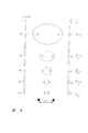
エネルギー孔の共鳴吸収の後、軌道球体の半径、aHはaH/m+1 に収縮し、共鳴収縮のpサイクルの後で、半径はaH/m+1である。換言すると、半径の基底状態の場はフーリエ成分の重ね合わせとみなされる。エネルギーmX27.2eV(mは整数)の負フーリエ成分を取り除くと、球体シェル内の中心電場は、陽子の負荷のm倍増加する。合成的な電場は、球体の座標のラプラース方程式の時間調和解法である。この場合、力均衡と非放射が達成される半径はαH/m+1(mは整数)である。「基底」状態からこの半径に崩壊する時、総エネルギー[(m+1)2-1 2]×13.6eVが放出される。エネルギー孔との衝突に作用される、2つの安定非放射状態の間の遷移は、2個の原子が二原子分子を形成する反応に類似している。この反応には、結合エネルギーを取り除くために、第3の物体との衝突が必要である。[N.V.Sidgwick,「化学元素とその化合物(The Chemical Elements and Their Compounds)」、Volume I,Oxford, Clarendon Press, (1950),p.17]。水素原子の総エネルギー源が、図1に示されている。1つの位置エネルギー準位からより低い準位への遷移に伴う発熱反応を、以下水素触媒作用(Hydro Catalysis)と呼ぶ。
After resonance absorption of the energy hole, the radius of the orbital sphere, a H , contracts to a H /
分数量子量数に相当する「基底状態」未満のエネルギー準位にある電子を持つ水素原子を、以下ハイドリノ(hydrino)原子と呼ぶ。半径a0/p(pは整数)のhydrino原子の記号はH[a0/p]である。
位置エネルギーの関数としての電子軌道球体のサイズが、図2に示されている。
3つの共鳴器空洞の結合に依存する効率的な触媒系は、カリウムに関連がある。例えば、カリウムの第2イオン化エネルギーは31.63eVである。このエネルギー孔は、明らかに共鳴吸収には高すぎる。しかし、K+がKに還元される時、4.34eVを放出する。その結果K+からK2+およびK+からKの結合は、純エネルギー変化27.28eVを持つ。
A hydrogen atom having an electron at an energy level lower than the “ground state” corresponding to the fractional quantum number is hereinafter referred to as a hydrino atom. The symbol of the hydrino atom of radius a 0 / p (p is an integer) is H [a 0 / p].
The size of the electron orbit sphere as a function of potential energy is shown in FIG.
An efficient catalyst system that relies on the coupling of three resonator cavities is related to potassium. For example, the second ionization energy of potassium is 31.63 eV. This energy hole is clearly too high for resonant absorption. However, when K + is reduced to K, it releases 4.34 eV. Consequently, the K + to K 2+ and K + to K bonds have a net energy change of 27.28 eV.

(エネルギー状態の不均化)
より低エネルギー水素原子、hydrinoは共鳴収縮を起こすエネルギー孔の源として機能できる。励起および/またはイオン化エネルギーはm×27.2eV(方程式(3))だからである。例えば、方程式(3)の27.21eV, m=1のエネルギー孔の吸収を表す方程式は、水素原子、H[αH/3]の第3サイクルの収縮カスケードの間、水素型原子H[αH/2]と共に、共鳴収縮を起こすエネルギー孔の源としてイオン化され、次式となる。
(Disproportionate energy state)
The lower energy hydrogen atom, hydrino, can act as a source of energy holes that cause resonance contraction. This is because the excitation and / or ionization energy is m × 27.2 eV (equation (3)). For example, 27.21 eV of equation (3), equation representing the absorption of m = 1 in the energy hole of a hydrogen atom, H [α H / 3] between the shrinkage cascade of the third cycle, the hydrogen nuclear H [alpha H / 2] is ionized as a source of energy holes that cause resonance contraction, and the following equation is obtained.
27.21eVの整数倍のエネルギー孔の吸収に伴う、非連続的なエネルギー準位への遷移は可能である。より低エネルギー水素原子、hydrinoはm×27.2eV(方程式(3))のエネルギー孔の吸収と共に共鳴収縮を起こす、エネルギー孔の源とし機能できる。従って、 Transition to a non-continuous energy level is possible with absorption of energy holes of integer multiples of 27.21 eV. The lower energy hydrogen atom, hydrino, can function as a source of energy holes, causing resonance contraction with the absorption of energy holes of m × 27.2 eV (Equation (3)). Therefore,
水素は、エネルギー孔の源である。水素のイオン化エネルギーは13.6eVである。不均化は、3個の水素原子の間に起こり得る。ここで2個の原子が第3の水素原子に27.21eVのエネルギー孔を供給する。従って、水素型原子、 Hydrogen is a source of energy holes. The ionization energy of hydrogen is 13.6 eV. Disproportionation can occur between three hydrogen atoms. Here two atoms supply a 27.21 eV energy hole to the third hydrogen atom. Therefore, a hydrogen atom,
暗黒の恒星間媒体と太陽の出力の大部分からのスペクトル線は、「暗黒恒星間媒体からのHydrinosのスペクトルデータ(Spectral Data of Hydrinos from the Dark Interstellar Medium)」およびMills の「太陽」節で解説されている、不均化反応に帰することができる[Mills, R.,「正統量子力学の総括統一論(The grand Unified Theory of Classical Quantum Mechanics)」、(1995),Techonomic Publishing company, Lancaster, PA]。この帰属は、暗黒物質のミステリー太陽の中性微子問題、太腸黒点の原因と他の太陽活動のミステリー、および太陽がX線を放出する理由などを解明する。また、それは音速の急激な変化および半径0.7、太陽半径0.7Rsでの「放射層」から「対流層」ヘの遷移の理由を提供する。これは、後述の例4でまとめられている Spectral lines from the dark interstellar medium and most of the solar output are described in “Spectral Data of Hydrinos from the Dark Interstellar Medium” and Mills “Sun” section. Can be attributed to the disproportionation reaction [Mills, R., "The grand Unified Theory of Classical Quantum Mechanics", (1995), Technological Publishing company, Lancaster, PA]. This assignment elucidates the mystery problem of dark matter mysteries, the cause of the large bowel sunspot and other solar activities, and why the sun emits X-rays. It also provides the reason for the sudden change in sound velocity and the transition from "radiation layer" to "convection layer" at radius 0.7, solar radius 0.7Rs. This is summarized in Example 4 below.
(エネルギー孔(原子水素))
望ましい実施例では、エネルギー孔(それぞれおよそ27.21eV)は、電気化学反応体(電気触媒作用イオンかカップル)を含む、反応体の電子伝達反応によって供給される。電気化学反応体は、それらの電子が「基底状態」未満の量子化された位置エネルギー準位に、緩和するよう誘導される時、水素原子から熱を放出させる。電子伝達反応、エネルギー孔によって取り除かれるエネルギーは、放出される水素エネルギーと共鳴し、この遷移を誘導する。電解質エネルギー反応装置の場合は水の電解の間、および加圧気体エネルギー反応装置か気体放電エネルギー反応装置の場合は、水素ガスか水素化物の電解の間に、水素原子の源が陰極表面で生成される。
(Energy hole (atomic hydrogen))
In the preferred embodiment, the energy holes (approximately 27.21 eV each) are provided by electron transfer reactions of the reactants, including electrochemical reactants (electrocatalytic ions or couples). Electrochemical reactants release heat from hydrogen atoms when their electrons are induced to relax to quantized potential energy levels below the “ground state”. The energy removed by the electron transfer reaction, the energy hole, resonates with the released hydrogen energy and induces this transition. A source of hydrogen atoms is generated at the cathode surface during the electrolysis of water in the case of electrolyte energy reactors and during the electrolysis of hydrogen gas or hydride in the case of pressurized gas energy reactors or gas discharge energy reactors. Is done.
(水素型分子と分子イオンの「基底状態」未満の遷移)
2個の水素原子は、二原子分子、水素分子を形成するよう反応する。
(Transitions less than the “ground state” between hydrogen-type molecules and molecular ions)
Two hydrogen atoms react to form a diatomic molecule, a hydrogen molecule.
![]()
![]()
![]()
![]()
水素型分子の中心力方程式は、円形、楕円形、放物線、または双曲線の軌道解である。前の2つのタイプの解法は、原子と分子の軌道関数と関連づけられる。 「空間時間、力、物質、エネルギーの統一(The Unification of Spacetime, the Forces, Matter, and Energy)」, Mills, R., Technomic Publishing Company, Lancaster, Pa, (1992)の「1電子原子」の節で与えられた非放射の境界条件が満たされるならば、これらの解は非放射である。ゼロ放射の数理的公式化は、電子の運動を記述する関数が光速で進行する波動と、同期の空間時間フーリエ成分を持ってはいけない。角周波数が下の時、軌道球体の境界条件は満たされる。 The central force equation for hydrogen-type molecules is a circular, elliptical, parabolic, or hyperbolic orbital solution. The previous two types of solutions are associated with atomic and molecular orbitals. "The Unification of Spacetime, the Forces, Matter, and Energy", Mills, R., Technomic Publishing Company, Lancaster, Pa, (1992) These solutions are nonradiative if the nonradiative boundary conditions given in Section are satisfied. The mathematical formulation of zero emission should not have a wave whose function describing the motion of an electron travels at the speed of light and a synchronized spatio-temporal Fourier component. When the angular frequency is lower, the orbital sphere boundary condition is satisfied.
![]()
![]()
「空間時間、力、物質、エネルギーの統一 (The Unification of Spacetime, the Force Matter, and Energy)」,Mills,R., Technomic Publishing Company, Lancaster, PA(1992)の「1電子原子」の節で論証されているように、半径のディラックデルタ関数と時間調和関数の生成物関数では、この条件は満たされる。この時、角周波数、wは定数で方程式(21)で与えられる。 `` The Unification of Spacetime, the Force Matter, and Energy '', Mills, R., Technomic Publishing Company, Lancaster, PA (1992) As demonstrated, this condition is satisfied for the Dirac delta function of the radius and the product function of the time harmonic function. At this time, the angular frequency w is a constant and is given by equation (21).
この時、Lは角運動量で、Aは閉じられた測地線軌道の面積である。二次元の楕円体と時間調和関数の生成物を含む、中心力方程式の解を考慮しなさい。生成物関数の空間部は、楕円体の方程式を持つ半径のディラックデルタ関数の回旋である。2つの関数の回旋のフーリエ変換は、個々の関数のフーリエ変換の生成物である;従って下の時、楕円体の時間調和関数境界条件は満たされる。 At this time, L is the angular momentum, and A is the area of the closed geodesic orbit. Consider the solution of the central force equation, including a two-dimensional ellipsoid and a product of time harmonics. The space part of the product function is the convolution of a radial Dirac delta function with an ellipsoidal equation. The Fourier transform of the convolution of two functions is the product of the Fourier transform of the individual functions; therefore, when below, the ellipsoidal time harmonic boundary condition is satisfied.
![]()
A=πab (24)
![]()
A = πab (24)
2bは半短径の長さで、2aは半長径の長さである。幾何学的分子水素は、核間軸を主軸に持つ楕円形である;従って、電子軌道は二次元楕円体の時間調和関数である。質量は、焦点で陽子の中心場によって決定される際、測地線の時間に調和して続く。更に、核間軸の回転対称は、軌道が長球であることを決定する。一般的に、分子結合の楕円体の軌道(以下、楕円体分子軌道関数(M.O.‘s)と呼ぶ)は、次の一般方程式で表される。
X2/a2+y2/b2+Z2/c2=1 (25)
楕円体の半主軸はa, b, cである。
楕円体の座標でラプラシアンは、
2b is the length of the semimajor axis, and 2a is the length of the semimajor axis. The geometric molecular hydrogen is an ellipse with the internuclear axis as the principal axis; thus, the electron orbit is a time-harmonic function of a two-dimensional ellipsoid. The mass continues in time with the geodesic time as determined by the central field of the proton at the focal point. Furthermore, the rotational symmetry of the internuclear axis determines that the trajectory is an oval. In general, the orbit of a molecular bond ellipsoid (hereinafter referred to as an ellipsoidal molecular orbital function (MO's)) is represented by the following general equation.
X 2 / a 2 + y 2 / b 2 + Z 2 / c 2 = 1 (25)
The semi-major axes of the ellipsoid are a, b and c.
Laplacian in ellipsoid coordinates is
![]()
![]()
楕円体のM.O.は、方程式(25)によって与えられる表面を持つ電荷導体と同等である。これは総電荷qを持ち、その電位は楕円体座標、方程式(26)のラプラシアン解法である。
軌道球体の励起状態は、「空間時間、力、物質、エネルギーの統一(The Unification of Sapcetime, The Forces, Matter and Energy)」Mills, R., Technomic Publishing Company, Lancaster, PA, (1992)の「1電子原子(量子化)」の節の励起状態の中で論じられている。楕円体M.O.‘sの場合、離散的な周波数の光子がM.O.の楕円体の共鳴器空洞で捕獲される時、電子の励起状態が生成される。光子は、中心場が楕円体であるM.O.表面で有効電荷を変化させる。力均衡は、基底状態楕円体と共焦点である、楕円体の等電位二次元表面の系列で達成される。捕獲された光子は、楕円体座標、方程式(26)のラプラシアン解法である。
軌道球体の場合のように、より高エネルギー状態とより低エネルギー状態は等しく有効である。両方の場合の光予定常波は、楕円体座標のラプラシアン解法である。楕円体の共鳴器空洞にとって、許容円周、4aEと光子定常波、1の関係は
The MO of an ellipsoid is equivalent to a charge conductor with a surface given by equation (25). It has a total charge q and its potential is ellipsoidal coordinates, the Laplacian solution of equation (26).
The excited state of the orbital sphere is described in `` The Unification of Sapcetime, The Forces, Matter and Energy, '' Mills, R., Technomic Publishing Company, Lancaster, PA, (1992). It is discussed in the excited states in the section “One-electron atom (quantization)”. In the case of ellipsoid MO's, an excited state of electrons is generated when photons of discrete frequencies are captured in the resonator cavity of the MO ellipsoid. Photons change the effective charge on the MO surface where the central field is an ellipsoid. Force balance is achieved with a series of ellipsoidal equipotential two-dimensional surfaces that are confocal with the ground state ellipsoid. The captured photons are ellipsoidal coordinates, the Laplacian solution of equation (26).
As in the orbiting sphere, the higher energy state and the lower energy state are equally effective. The expected light wave in both cases is a Laplacian solution of ellipsoid coordinates. For an ellipsoidal resonator cavity, the relationship between the permissible circumference, 4aE and
4aE=nλ (27)
この時、nは整数である。また、
4 a E = nλ (27)
At this time, n is an integer. Also,
![]()
![]()
a1とb1はn=1の許容半長径と半短径
方程式(29)から、水素分子の「基底状態」未満の遷移に対応する楕円場のマグニチュードは整数である。水素型分子の位置エネルギー方程式は
For a 1 and b 1 , the magnitude of the elliptic field corresponding to the transition below the “ground state” of the hydrogen molecule is an integer from the allowed half major axis and half minor axis equation (29) of n = 1. The potential energy equation for hydrogen-type molecules is
また、pは整数である。エネルギー保存の法則から、次の遷移 P is an integer. From the law of conservation of energy, the next transition
mp2×48.6eV (36)
この時、mとpは整数である。遷移の間、楕円場はマグニチュードpからマグニチュードp+mに増大する。対応する位置エネルギー変化は、エネルギー孔によって吸収されるエネルギーに等しい。
エネルギー孔=-Ve-Vp=mp2×48.6ev (37)
核間距離が「収縮する」につれて、更なるエネルギーが水素型分子によって放出される。遷移の間に放出される総エネルギー、ETは、
mp 2 × 48.6eV (36)
At this time, m and p are integers. During the transition, the elliptic field increases from magnitude p to magnitude p + m. The corresponding potential energy change is equal to the energy absorbed by the energy holes.
Energy hole = -Ve-Vp = mp 2 × 48.6ev (37)
As the internuclear distance “shrinks”, additional energy is released by the hydrogen-type molecules. The total energy released during the transition, E T, is
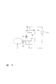
水素型分子と分子イオンの総エネルギー源の概略図が図3にある。また、1つの位置エネルギー準位から「基底状態」未満のより低い準位への遷移を伴う発熱反応を、以下水素触媒作用(HydroCatalysis)と呼ぶ。
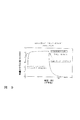
分数量子数に相当する「基底状態」より低エネルギー準位の電子を持つ水素型分子を以下dihydrino分子と呼ぶ。核間距離、2C=√2α0/p(pは整数)のdihydrino分子の記号はH* 2[2c=√2α0/P]である。総エネルギーの関数としての水素型分子のサイズの概略図が図4にある。
A schematic of the total energy source for hydrogen-type molecules and molecular ions is shown in FIG. Further, an exothermic reaction accompanied by a transition from one potential energy level to a lower level lower than the “ground state” is hereinafter referred to as hydrogen catalysis.
A hydrogen-type molecule having electrons of lower energy level than the “ground state” corresponding to the fractional quantum number is hereinafter referred to as a dihydrino molecule. The symbol of the dihydrino molecule with an internuclear distance of 2C = √2α 0 / p (p is an integer) is H * 2 [2c = √2α 0 / P]. A schematic diagram of the size of hydrogen-type molecules as a function of total energy is shown in FIG.
第一の「基底状態」未満の水素型分子に対応する楕円場のマグニチュードは2である。エネルギー保存の法則から、核間距離2C=√2aを持つ水素分子が、核間距離2c=1/2 a0を持つ第1の「基底状態」未満ヘ遷移するよう励起する水素分子の共鳴エネルギー孔は、方程式(30)と(31)で与えられる。この時、楕円場はマグニチュード1からマグニチュード2に増大する:
The magnitude of the elliptic field corresponding to hydrogen-type molecules below the first “ground state” is 2. From the law of conservation of energy, the resonance energy of a hydrogen molecule excited so that a hydrogen molecule having an internuclear distance of 2C = √2a transitions to less than the first “ground state” having an internuclear distance of 2c = 1/2 a 0 The hole is given by equations (30) and (31). At this time, the elliptic field increases from
換言すると、水素分子の楕円体の「基底状態」の場は、フーリエ成分の重ね合わせとみなされる。エネルギーの負フーリエ成分
m×48.6eV (42)
(mは整数)を取り除くと、楕円体のシェル内の陽電場は、それぞれの焦点で陽子の電荷のm倍増加する。合成的な電場は、楕円座標のラプラシアン時間調和解法である。核間距離2c’=√2a0を持つ水素分子は、「基底状態」未満の準位に遷移し、力均衡と非放射が達成されるための核間距離は2C’=√2a0/1+mである。「基底状態」からこの核間距離に崩壊する際、総エネルギー
In other words, the “ground state” field of an ellipsoid of hydrogen molecules is regarded as a superposition of Fourier components. Negative Fourier component of energy
m × 48.6eV (42)
Removing (m is an integer), the positive electric field in the ellipsoidal shell increases m times the proton charge at each focal point. The synthetic electric field is an elliptic coordinate Laplacian time-harmonic solution. Hydrogen molecules with internuclear distance 2c ′ = √2a 0 transition to a level below the “ground state”, and the internuclear distance for achieving force balance and non-radiation is 2C ′ = √2a 0/1 + m. When decaying from the "ground state" to this internuclear distance, the total energy
(エネルギー孔(分子水素))
望ましい実施例では、エネルギー孔、それぞれおよそ
m×48.6eVは、電気化学反応体(電気触媒作用イオンかカップル)を含む、反応体の電子伝達反応によって供給される。電気化学反応体によって、電子が「基底状態」未満の量子化された位置エネルギー準位に緩和するよう誘導される際、熱が水素分子から放出される。電子伝達反応によって取り除かれるエネルギー、エネルギー孔は、この遷移を誘導するために放出される水素エネルギーと共鳴する。水素分子の源は、電解エネルギー反応装置の場合は水の電解の間、および加圧気体エネルギー反応装置か気体放電エネルギー反応装置の場合は、水素ガスか水素化物の電解の間に、陰極表面上で生成される。
(Energy hole (molecular hydrogen))
In the preferred embodiment, energy holes, each approximately
m × 48.6 eV is supplied by the electron transfer reaction of the reactant, including the electrochemical reactant (electrocatalytic ion or couple). As the electrochemical reactant induces the electrons to relax to a quantized potential energy level below the “ground state”, heat is released from the hydrogen molecule. The energy removed by the electron transfer reaction, the energy hole, resonates with the hydrogen energy released to induce this transition. The source of molecular hydrogen is on the cathode surface during electrolysis of water in the case of an electrolysis energy reactor and during electrolysis of hydrogen gas or hydride in the case of a pressurized gas energy reactor or gas discharge energy reactor. Is generated.
(エネルギー反応装置)
この発明は、電解槽エネルギー反応装置、加圧気体エネルギー反応装置、および気体放電エネルギー反応装置などから成り、次を合む:水素源;1つの個体、熔融、液体、および気体のエネルギー孔の源;水素とエネルギー孔の源を含む容器(中で水素とエネルギー孔の源との接触によって収縮反応が起こる);および発熱性の収縮反応が平衡になることを防ぐために、(分子の)より低エネルギー水素を取り除く方法。共鳴収縮エネルギーと釣り合うようにエネルギー孔を適合させることによって、収縮反応速度と純出力は増加する。概して、温度、水素ガスの圧力、電気触媒作用イオンかカップルを合むエネルギー孔の源を調節することによって、出力を最適化できる。エネルギー孔の源は、エネルギー孔、電気触媒作用イオンかカップルの対イオン、および収縮反応が起こる表面積を供給する。更にこの発明は、分子水素を解離する官能基を持つ多官能基物質から成り、水素あふれ出し触媒、自由水素原子を供給する。自由水素原子は、可動の自由水素原子を支持する官能基、およびエネルギー孔の源となり得る官能基にあふれ出す。
望ましい水素ガス加圧エネルギー反応装置は以下を含む:容器;水素源;水素の圧力と水素の容器ヘの流れを調節する方法;分子水素を原子水素に解離する物質、および気相でエネルギー孔の源であり得る物質。エネルギー孔の気体の源は、気体エネルギー反応装露の高い運転温度で昇華、沸騰、および/または揮発するものを含む。この反応装置内で、気相で収縮反応が起こる。
この発明の他の目的、特徴、特質、および関連要素の操作法や機能は、後述の説明およびそれに付随した図とその解説を考察すると明瞭になるだろう。これらは全て、この詳述に関連があり、参照番号はこれらの図の対応する部分を示す。
(Energy reactor)
The present invention comprises an electrolytic cell energy reactor, a pressurized gas energy reactor, a gas discharge energy reactor, etc., and combines the following: a hydrogen source; a source of energy holes for one solid, a melt, a liquid, and a gas A container containing a source of hydrogen and energy pores (in which the contraction reaction occurs due to contact with the source of hydrogen and energy pores); and lower (molecular) to prevent the exothermic shrinkage reaction from equilibrating How to remove energy hydrogen. By adapting the energy holes to balance the resonant contraction energy, the contraction kinetics and net power are increased. In general, the output can be optimized by adjusting the temperature, the pressure of hydrogen gas, and the source of energy holes that couple the electrocatalytic ions or couple. The source of energy holes provides energy holes, electrocatalytic ions or a couple of counter ions, and the surface area at which the contraction reaction takes place. The present invention further comprises a polyfunctional material having a functional group capable of dissociating molecular hydrogen, and supplies a hydrogen overflow catalyst and free hydrogen atoms. Free hydrogen atoms overflow with functional groups that support mobile free hydrogen atoms and functional groups that can be sources of energy holes.
A preferred hydrogen gas pressurized energy reactor includes: a vessel; a hydrogen source; a method of regulating the pressure of hydrogen and the flow of hydrogen to the vessel; a material that dissociates molecular hydrogen into atomic hydrogen, and an energy hole in the gas phase. A substance that can be a source. Sources of energy pore gases include those that sublime, boil, and / or volatilize at high operating temperatures of gaseous energy reaction dew. Within this reactor, a contraction reaction takes place in the gas phase.
Other objects, features, characteristics, and operation methods and functions of the related elements of the present invention will be apparent from the following description and the accompanying drawings and descriptions thereof. All of these are relevant to this detail, and the reference numbers indicate the corresponding parts of these figures.
(現在望ましい実施例の詳細な説明)
(原子の触媒エネルギー孔の構造)
(単電子励起状態)
エネルギー孔は、原子、イオン、分子、およびイオンや分子の化合物の励起状態の連続体を含む励起状態の種ヘの、ある種の電子からの遷移によって供給される。1つの実施例でエネルギー孔は、1つの種の電子の励起状態の遷移から成る。この時、アクセプタ種の遷移エネルギーは、およそm×27.21eV(mは整数)に等しい。
(Detailed description of presently preferred embodiment)
(Atom catalytic energy pore structure)
(Single electron excited state)
The energy holes are provided by transitions from certain electrons to excited state species, including continuums of excited states of atoms, ions, molecules, and compounds of ions and molecules. In one embodiment, the energy hole comprises an excited state transition of one species of electron. At this time, the transition energy of the acceptor species is approximately m × 27.21 eV (m is an integer).
(単電子伝達)
エネルギー孔は、原子、イオン、分子、およびイオンや分子の化合物を含む、関与している種の間の電子伝達によって供給される。1つの実施例でエネルギー孔は、1つの種から別の種ヘの電子伝達から成る。この時、電子ドナー種のイオン化エネルギーの合計から、電子アクセプタ種のイオン化エネルギーの電子親和カを引いたものは、およそm×27.21eV(mは整数)に等しい。
(Single electron transfer)
Energy holes are provided by electron transfer between participating species, including atoms, ions, molecules, and compounds of ions and molecules. In one embodiment, the energy hole consists of electron transfer from one species to another. At this time, the sum of the ionization energies of the electron donor species minus the electron affinity of the ion acceptor species is approximately m × 27.21 eV (m is an integer).
(単電子伝達(2種))
3個の共鳴器空洞の結合に依存する効率的な触媒系は、カリウムに関連がある。例えば、カリウムの第2イオン化エネルギーは31.63eVである。このエネルギー孔は、明らかに共鳴吸収にとって高すぎる。しかし、K+はKに還元される時、4.34eVを放出する。K+からK2+とK+とKの化合は、その結果、方程式(3)で純エネルギー変化、27.28eV;m=1を持つ。
(Single electron transfer (2 types))
An efficient catalyst system that relies on the coupling of three resonator cavities is related to potassium. For example, the second ionization energy of potassium is 31.63 eV. This energy hole is clearly too high for resonant absorption. However, K + releases 4.34 eV when reduced to K. The combination of K + to K 2+ and K + and K results in a net energy change of 27.28 eV; m = 1 in equation (3).
原子が収縮するにつれて放出されるエネルギーが、エネルギー孔に失われるエネルギーよりもはるかに大きい点に着目すべきである。また、放出されるエネルギーも、従来の化学反応に比較すると大きい。
ナトリウムがナトリウムイオンでは、およそ27.21eVの電気触媒作用反応は全く不可能である。例えば、42.15eVのエネルギーは、方程式(45)(K+をNa+に置き替え)で与えられる反応の逆によって吸収される。
Na++Na++42.15eV→Na+Na2+ (47)
他のそれほど効率的でない触媒系は3個の共鳴器空洞の結合に依存する。例えば、パラジウムの第3のイオン化エネルギーは32.93eVである。このエネルギー孔は、明らかに共鳴吸収にとって高すぎる。しかし、Li+はLiに還元される時、5.392eVを放出する。Pd2+からpd3+とLi+からLiの化合は、その結果、純エネルギー変化27.54eVを持つ。
It should be noted that the energy released as the atoms contract is much greater than the energy lost to the energy holes. Also, the energy released is large compared to conventional chemical reactions.
When sodium is a sodium ion, an electrocatalytic reaction of approximately 27.21 eV is completely impossible. For example, 42.15 eV of energy is absorbed by the inverse of the reaction given by equation (45) (replace K + with Na + ).
Na + + Na + + 42.15eV → Na + Na 2+ (47)
Other less efficient catalyst systems rely on the coupling of three resonator cavities. For example, the third ionization energy of palladium is 32.93 eV. This energy hole is clearly too high for resonant absorption. However, Li + releases 5.392 eV when reduced to Li. The combination of Pd 2+ to pd 3+ and Li + to Li has a net energy change of 27.54 eV.
(単電子伝達(1種))
エネルギー孔は、原子、イオン、分子、およびイオン化分子の化合物を含む関与している種から、真空エネルギー準位への電子のイオン化によって供給される。1つの実施例でエネルギー孔は、1つの種から真空エネルギー準位への電子のイオン化から成る。この時、電子ドナ一種のイオン化エネルギーはおよそm×27.21eV (mは整数)に等しい。
チタンは、第3のイオン化エネルギーが方程式(3)で27.49eV、m=1なので共鳴収縮を起こすことができる1個の触媒(電気触媒作用イオン)である。従って、p番目のサイクルの収縮カスケードは次式となる。
(Single electron transfer (1 type))
Energy holes are provided by ionization of electrons from participating species, including atoms, ions, molecules, and compounds of ionized molecules, to vacuum energy levels. In one embodiment, the energy hole consists of ionization of electrons from one species to a vacuum energy level. At this time, the ionization energy of a kind of electron donor is approximately m × 27.21 eV (m is an integer).
Titanium is one catalyst (electrocatalytic ion) that can cause resonance contraction because the third ionization energy is 27.49 eV and m = 1 in equation (3). Therefore, the contraction cascade of the pth cycle is
およそm×27.2leV(mは整数)のエネルギー孔を供給する他の単電子伝達反応は、 私の先の米国特許出願に記述されており、ここに参照する:タイトル「エネルギー/物質転換方法と構造(Energy/Matter Conversion Methods and Structures)」、通し番号08/467,051、1995年6月6日提出、一部継続出願、通し番号08/416,040、1995年4月3日提出、一部継続出願、通し番号08/107,357、1993年8月16日提出、一部継続出願、通し番号08/075,102(Dkt.99437)、1993年6月11日提出、一部継続出願、通し番号07/626,496、1990年12月12日提出、一部継続出願、通し番号07/345,628、1989年4月28日提出、一部継続出願、通し番号07/341,733、1989年4月21日提出。 Another single electron transfer reaction that provides an energy hole of approximately m × 27.2 leV (where m is an integer) is described in my earlier US patent application and is referred to here: the title “Energy / Matter Conversion Method and `` Energy / Matter Conversion Methods and Structures '', serial number 08 / 467,051, filed on June 6, 1995, partially continued application, serial number 08 / 416,040, filed on April 3, 1995, partially continued application, serial number 08 / 107,357, filed August 16, 1993, partially continued application, serial number 08 / 075,102 (Dkt.99437), filed June 11, 1993, partially continued application, serial number 07 / 626,496, December 12, 1990 Submitted, partially continued, serial number 07 / 345,628, filed April 28, 1989, partially continued, serial number 07 / 341,733, filed April 21, 1989.
(多電子伝達)
エネルギー孔は、原子、イオン、分子、およびイオンや分子の化合物を含む、関与している種の間の多電子伝達によって供給される。1つの実施例でエネルギー孔は、1つ以上の種から1つ以上の種ヘのt電子の伝達から成る。この時、電子ドナー一種のイオン化エネルギーおよび/または電子親和力の合計から、電子アクセプタ種のイオン化エネルギーおよび/または電子親和力の合計を引いたものは、およそm×27.2leV(mとtは整数)に等しい。
(Multi-electron transmission)
Energy holes are provided by multi-electron transfer between participating species, including atoms, ions, molecules, and compounds of ions and molecules. In one embodiment, the energy hole consists of the transfer of t electrons from one or more species to one or more species. At this time, the sum of the ionization energy and / or electron affinity of the electron donor species minus the sum of the ionization energy and / or electron affinity of the electron acceptor species is approximately m × 27.2 leV (m and t are integers). equal.
エネルギー孔は、原子、イオン、分子、およびイオンや分子の化合物を含む、関与している種の間の多電子の伝達によって供給される。1つの実施例でエネルギー孔は、1つの種から別の種ヘのt電子の伝達から成る。この時、tの連続電子ドナー種の電子親和カおよび/またはイオン化エネルギーから、tの連続電子アクセプタのイオン化エネルギーおよび/または電子親和力を引いたものは、およそm×27.2leV(nとtは整数)に等しい。
望ましい実施例では、電子アクセプタ種はMnOx, AIOx, SiOxのような酸化物である。望ましい分子電子アクセプタは、酸素、O2である。
Energy holes are provided by the transfer of multiple electrons between participating species, including atoms, ions, molecules, and compounds of ions and molecules. In one embodiment, the energy hole consists of the transfer of t electrons from one species to another species. At this time, the value obtained by subtracting the ionization energy and / or the electron affinity of the continuous electron acceptor of t from the electron affinity and / or ionization energy of the continuous electron donor species of t is approximately m × 27.2 leV (n and t are integers). )be equivalent to.
In the preferred embodiment, the electron acceptor species is an oxide such as MnO x , AIO x , SiO x . A desirable molecular electron acceptor is oxygen, O 2 .
(2電子伝達(1種))
1つの実施例では、エネルギー孔を供給する触媒系は、原子、イオン、または分子から真空エネルギー準位ヘの2個の電子のイオン化に依存する。この時、2つのイオン化エネルギーの合計はおよそ27.2leVである。亜鉛は、第1と第2のイオン化エネルギーの合計が方程式(3)で、27.358eV、m=1なので、共鳴収縮を引き起こすことができる1個の触媒(電気触媒作用原子)である。従って、p番目のサイクルの収縮カスケードは次式となる。
(2 electron transfer (1 type))
In one embodiment, the catalyst system providing the energy holes relies on the ionization of two electrons from an atom, ion, or molecule to the vacuum energy level. At this time, the sum of the two ionization energies is approximately 27.2 leV. Zinc is one catalyst (electrocatalytic atom) that can cause resonance shrinkage because the sum of the first and second ionization energies is Equation (3), 27.358 eV, m = 1. Therefore, the contraction cascade of the pth cycle is
(2電子伝達(2種))
他の実施例では、エネルギー孔を供給する触媒系は、1個の原子、イオン、または分子から別の原子か分子ヘの、2個の電子の伝達に依存する。この時、2つのイオン化エネルギーの合計から、関与している原子、イオン、および/または分子の2つの電子親和力の合計を引いたものは、およそ27.2leVである。原子から分子ヘの2個の電子の伝達に依存する触媒系は、パラジウムと酸素に関連がある。例えば、パラジウムの第1と第2のイオン化エネルギーは、それぞれ8.34eVとl9.43eVである。そして、酸素分子の第1と第2の電子親和力は、それぞれ0.45eVと0.l1eVである。2電子伝達の結果のエネルギー孔は、共鳴吸収に適当である。Pd2+とO2からO2 2−の化合は、その結果、27.21eVの純エネルギー変化を持つ。
(2-electron transfer (2 types))
In other embodiments, the catalyst system providing the energy hole relies on the transfer of two electrons from one atom, ion, or molecule to another atom or molecule. At this time, the sum of the two ionization energies minus the sum of the two electron affinities of the atoms, ions and / or molecules involved is approximately 27.2 leV. A catalyst system that relies on the transfer of two electrons from atom to molecule is related to palladium and oxygen. For example, the first and second ionization energies of palladium are 8.34 eV and l9.43 eV, respectively. The first and second electron affinities of oxygen molecules are 0.45 eV and 0.11 eV, respectively. The energy hole resulting from the two-electron transfer is suitable for resonant absorption. The combination of Pd 2+ and O 2 to O 2 2− results in a net energy change of 27.21 eV.
(2電子伝達(2種))
他の実施例では、エネルギー孔を供給する触媒系は、1個の原子、イオン、または分子から別の原子、イオン、または分子への2個の電子の伝達に依存する。この時、2つのイオン化エネルギーの合計から、関与している原子、イオン、および/または分子の1つのイオン化エネルギーと1つの電子親和力の合計を引いたものは、およそ27.2leVである。原子からイオンへの2個の電子の伝達に依存する触媒系は、キセノンとリチウムに関連がある。例えばキセノンの第1と第2のイオン化エネルギーは、それぞれl2.l3eVと2l.2leVである。そして、リチウムの第1イオン化エネルギーと第1電子親和力は、それぞれ5.39eVと0.62eVである。2電子伝達の結果のエネルギー孔は、共鳴吸収に適当である。XeからXe2+とLi+からLi-の化合は、その結果、27.33eVの純エネルギー変化を持つ。
(2-electron transfer (2 types))
In other embodiments, the catalyst system providing the energy holes relies on the transfer of two electrons from one atom, ion, or molecule to another atom, ion, or molecule. At this time, the sum of the two ionization energies minus the sum of one ionization energy and one electron affinity of the atom, ion and / or molecule involved is approximately 27.2 leV. A catalyst system that relies on the transfer of two electrons from an atom to an ion is related to xenon and lithium. For example, the first and second ionization energies of xenon are l2.l3eV and 2l.2leV, respectively. The first ionization energy and the first electron affinity of lithium are 5.39 eV and 0.62 eV, respectively. The energy hole resulting from the two-electron transfer is suitable for resonant absorption. From Xe 2+ and Li + Li from xe - compounds of, then, has a net energy change of 27.33EV.
(2電子伝達(2種))
他の実施例では、エネルギー孔を供給する触媒系は、1個の原子、イオン、または分子から別の原子、イオン、または分子への2個の電子の伝達に依存する。この時、2つのイオン化エネルギーの合計から、関与している原子および/または分子の2つのイオン化エネルギーの合計を引いたものは、およそ27.2leVである。第1イオンから第2イオンヘの2個の電子の伝達に依存する触媒系は、銀(Ag+)と銀(Ag2+)に関連がある。例えば、銀の第2と第3のイオン化エネルギーは、それぞれ2l.49eVと34.83eVである。そして、銀の第2と第3のイオン化エネルギーは、それぞれ21.49eVと7.58eVである。2電子伝達の結果のエネルギー孔は、共鳴吸収に適当である。Ag+からAg3+とAg2+からAgの化合は、その結果、27.25eVの純エネルギー変化を持つ。
(2-electron transfer (2 types))
In other embodiments, the catalyst system providing the energy holes relies on the transfer of two electrons from one atom, ion, or molecule to another atom, ion, or molecule. At this time, the sum of the two ionization energies minus the sum of the two ionization energies of the atoms and / or molecules involved is approximately 27.2 leV. A catalyst system that relies on the transfer of two electrons from the first ion to the second ion is related to silver (Ag + ) and silver (Ag 2+ ). For example, the second and third ionization energies of silver are 2l.49 eV and 34.83 eV, respectively. The second and third ionization energies of silver are 21.49 eV and 7.58 eV, respectively. The energy hole resulting from the two-electron transfer is suitable for resonant absorption. The combination of Ag + to Ag 3+ and Ag 2+ to Ag results in a net energy change of 27.25 eV.
(3電子伝達(2種))
他の実施例では、エネルギー孔を供給する触媒系は、1個のイオンから別のイオンヘの3個の電子の伝達に依存する。この時、第1イオンの電子親和力と2つのイオン化エネルギーの合計から、第2イオンの3つのイオン化エネルギーの合計を引いたものは、およそ27.2leVである。1個のイオンから第2イオンへの3個の電子の伝達に依存する触媒系は、Li-とCr3+に関連がある。例えば、リチウムの電子親和力、第1イオン化エネルギー、および第2イオン化エネルギーはそれぞれ、0.62eV、5.392eV、および75.638eVである。そして、Cr3+の第3、第2、および第1のイオン化エネルギーはそれぞれ、30.96eV、16.50eV、および6.766eVである。3電子伝達の結果のエネルギー孔は、共鳴吸収に適当である。Li-からLi2+とCr3+からCrの化合は、その結果27.42eVの純エネルギー変化を持つ。
(3 electron transfer (2 types))
In other embodiments, the catalyst system providing the energy holes relies on the transfer of three electrons from one ion to another. At this time, the sum of the electron affinity of the first ions and the two ionization energies minus the sum of the three ionization energies of the second ions is approximately 27.2 leV. A catalyst system that relies on the transfer of three electrons from one ion to a second ion is related to Li - and Cr 3+ . For example, the electron affinity, first ionization energy, and second ionization energy of lithium are 0.62 eV, 5.392 eV, and 75.638 eV, respectively. The third, second, and first ionization energies of Cr 3+ are 30.96 eV, 16.50 eV, and 6.766 eV, respectively. The energy hole resulting from the three-electron transfer is suitable for resonant absorption. The combination of Li - to Li 2+ and Cr 3+ to Cr has a net energy change of 27.42 eV.
(3電子伝達(2種))
他の実施例では、エネルギー孔を供給する触媒系は、原子、イオン、または分子から別の原子、イオン、または分子ヘの3個の電子の伝達に依存する。この時、電子ドナー種の3つの連続イオン化エネルギーの合計から、電子アクセプタ種の3つの連続イオン化エネルギーの合計を引いたものは、およそ27.21eVである。原子からイオンへの3個の電子の伝達に依存する触媒系は、AgとCe3+に関連がある例えば、銀の第1、第2、および第3のイオン化エネルギーはそれぞれ、7.58eV、2l.49eV、および34.83eVである。そして、Ce3+ の第3、第2、および第1のイオン化エネルギーはそれぞれ20.20eV、10.85eVおよび5.47eVである。3電子伝達の結果のエネルギー孔は、共鳴吸収に適当である。AgからAg3+とCe3+からCeの化合は、その結果、27.38eVの純エネルギー変化を持つ。
(3 electron transfer (2 types))
In other embodiments, the catalyst system providing the energy holes relies on the transfer of three electrons from one atom, ion, or molecule to another atom, ion, or molecule. At this time, the sum of the three consecutive ionization energies of the electron donor species minus the sum of the three consecutive ionization energies of the electron acceptor species is approximately 27.21 eV. A catalyst system that relies on the transfer of three electrons from an atom to an ion is related to Ag and Ce 3+. For example, the first, second, and third ionization energies of silver are 7.58 eV, 2 l, respectively. .49 eV, and 34.83 eV. The third, second, and first ionization energies of Ce 3+ are 20.20 eV, 10.85 eV, and 5.47 eV, respectively. The energy hole resulting from the three-electron transfer is suitable for resonant absorption. The combination of Ag to Ag 3+ and Ce 3+ to Ce results in a net energy change of 27.38 eV.
(付加的な触媒エネルギー孔の構造)
(単電子伝達)
更なる実施例では、水素原子の「基底状態」未満の電子遷移のために放出される、総エネルギーに等しいエネルギーのエネルギー孔は、原子、イオン、や分子、およびイオンや分子の化合物を含む、関与している種の間の電子の伝達によって供給される。1つの実施例でエネルギー孔は、1つの種から別の種への電子の伝達から成る。この時、電子ドナー種のイオン化エネルギーの合計から、電子アクセプタ種のイオン化エネルギーか電子親和力を引いたものは、およそm/2 ×27.21eV(mは整数)に等しい。
(Additional catalytic energy pore structure)
(Single electron transfer)
In a further embodiment, energy holes of energy equal to the total energy released for electronic transitions below the “ground state” of a hydrogen atom include atoms, ions, molecules, and compounds of ions and molecules, Supplied by the transfer of electrons between participating species. In one embodiment, the energy hole consists of the transfer of electrons from one species to another. At this time, the sum of the ionization energies of the electron donor species minus the ionization energy of the electron acceptor species or the electron affinity is approximately m / 2 × 27.21 eV (m is an integer).
n=1からn=1/2への遷移に相当するm=3にとって、3個の共鳴器空洞の結合に依存する効率的な触媒系は、ヒ素とカルシウムに関連がある。例えば、カルシウムの第3のイオン化エネルギーは50.908eVである。このエネルギー孔は、明らかに共鳴吸収にとって高すぎる。しかし、As+はAsに還元される時、9.81eVを放出する。 Ca2十からCa3+とAs+からAsの化合は、その結果、41.1eVの純エネルギー変化を持つ。 For m = 3, which corresponds to a transition from n = 1 to n = 1/2, an efficient catalyst system that relies on the coupling of three resonator cavities is related to arsenic and calcium. For example, the third ionization energy of calcium is 50.908 eV. This energy hole is clearly too high for resonant absorption. However, As + releases 9.81 eV when reduced to As. The combination of Ca 20 to Ca 3+ and As + to As results in a net energy change of 41.1 eV.
(多電子伝達)
エネルギー孔は、原子、イオン、分子、およびイオンや分子の化合物を含む、関与している種の間の多電子の伝達によって供給される。1つの実施例でエネルギー孔は、1つ以上の種から1つ以上の種へのt電子の伝達から成る。この時、電子ドナー種のイオン化エネルギーおよび/または電子親和力の合計から、電子アクセプタ種のイオン化エネルギーおよび/または電子親和力の合計を引いたものは、およそm/2×27.21eV(mとtは整数)に等しい。
(Multi-electron transmission)
Energy holes are provided by the transfer of multiple electrons between participating species, including atoms, ions, molecules, and compounds of ions and molecules. In one embodiment, the energy hole consists of the transfer of t electrons from one or more species to one or more species. At this time, the sum of the ionization energy and / or electron affinity of the electron donor species minus the sum of the ionization energy and / or electron affinity of the electron acceptor species is approximately m / 2 × 27.21 eV (m and t are integers). )be equivalent to.
(分子の触媒エネルギー孔構造)
(単電子励起状態)
エネルギー孔は、原子、イオン、分子、およびイオンや分子の化合物を含む、種から励起状態種への電子の遷移によって供給される。1つの実施例でエネルギー孔は、1つの種の電子の励起状態の遷移から成る。この時、アクセプタ種の遷移エネルギーは、mp2×48.6eV(mとpは整数)である。
(単電子伝達)
エネルギー孔は、原子、イオン、分子、およびイオンや分子の化合物を含む、関与している種の間の1個の電子の伝達によって供給される。1つの実施例でエネルギー孔は、1つの種から別の種への電子の伝達から成る。この時、電子ドナー種のイオン化エネルギーの合計から、電子アクセプタ種のイオン化エネルギーか電子親和力を引いたものは、およそmp2×48.6eV(mとpは整数)に等しい。
(Molecular catalytic energy pore structure)
(Single electron excited state)
Energy holes are provided by the transition of electrons from species to excited state species, including atoms, ions, molecules, and compounds of ions and molecules. In one embodiment, the energy hole comprises an excited state transition of one species of electron. At this time, the transition energy of the acceptor species is mp 2 × 48.6 eV (m and p are integers).
(Single electron transfer)
An energy hole is provided by the transfer of one electron between participating species, including atoms, ions, molecules, and compounds of ions and molecules. In one embodiment, the energy hole consists of the transfer of electrons from one species to another. At this time, the sum of the ionization energies of the electron donor species minus the ionization energy of the electron acceptor species or the electron affinity is approximately mp 2 × 48.6 eV (m and p are integers).
(単電子伝達(2種))
3個の共鳴器空洞の結合に依存する効率的な触媒系は、鉄とリチウムに関連がある。例えば、鉄の第4のイオン化エネルギーは54.8eVである。このエネルギー孔は、明らかに共鳴吸収にとって高すぎる。しかし、Li+はLiに還元される時5.392eVを放出する。Fe3+からFe4+とLi+からLiの化合は、その結果、49.4eVの純エネルギー変化を持つ。
(Single electron transfer (2 types))
An efficient catalyst system that relies on the coupling of three resonator cavities is related to iron and lithium. For example, the fourth ionization energy of iron is 54.8 eV. This energy hole is clearly too high for resonant absorption. However, Li + releases 5.392 eV when reduced to Li. The combination of Fe 3+ to Fe 4+ and Li + to Li thus has a net energy change of 49.4 eV.
分子が収縮するにつれて放出されるエネルギーが、エネルギー孔に失われるエネルギーよりもはるかに大きい点に着目すべきである。また、放出されるエネルギーも、従来の化学反応と比較すると大きい。
3個の共鳴器空洞の結合に依存する効率的な触媒系は、スカンジウムに関連がある。例えば、スカンジウムの第4のイオン化エネルギーは73.47eVである。このエネルギー孔は、明らかに共鳴吸収にとって高すぎる。しかし、Sc3+はSc2+に還元される時、24.76eVを放出するSc3+からSc4+とSc3+からSc2+ の化合は、その結果、48.7eVの純エネルギー変化を持つ。
It should be noted that the energy released as the molecule contracts is much greater than the energy lost to the energy holes. Also, the energy released is large compared to conventional chemical reactions.
An efficient catalyst system that relies on the coupling of three resonator cavities is related to scandium. For example, the fourth ionization energy of scandium is 73.47 eV. This energy hole is clearly too high for resonant absorption. However, when Sc 3+ is reduced to Sc 2+ , the combination of Sc 3+ to Sc 4+ and Sc 3+ to Sc 2+ release 24.76 eV, resulting in a net energy change of 48.7 eV. .
3個の共鳴器空洞の結合に依存する効率的な触媒系は、イットリウムに関連がある。例えば、ガリウムの第4のイオン化エネルギーは64.00eVである。このエネルギー孔は、明らかに共鳴吸収にとって高すぎる。しかし、Pb2+はPb+に還元される時、15.03eVを放出する。Ga3+からBa4+とPb2+からPb+の化合は、その結果、48.97eVの純エネルギー変化を持つ。 An efficient catalyst system that relies on the coupling of three resonator cavities is related to yttrium. For example, the fourth ionization energy of gallium is 64.00 eV. This energy hole is clearly too high for resonant absorption. However, Pb 2+ releases 15.03 eV when reduced to Pb + . The combination of Ga 3+ to Ba 4+ and Pb 2+ to Pb + results in a net energy change of 48.97 eV.
(単電子伝達(1種))
エネルギー孔は、原子、イオン、分子、およびイオンや分子の化合物を含む関与している種から、真空エネルギー準位への電子のイオン化によって供給される。1つの実施例でエネルギー孔は、1つの種から真空エネルギー準位への、電子のイオン化から成る。この時、電子ドナー種のイオン化エネルギーは、およそmp2×48.6eV(mとpは整数)に等しい。
(Single electron transfer (1 type))
Energy holes are supplied by ionization of electrons from participating species, including atoms, ions, molecules, and compounds of ions and molecules, to vacuum energy levels. In one embodiment, the energy hole consists of ionization of electrons from one species to a vacuum energy level. At this time, the ionization energy of the electron donor species is approximately equal to mp 2 × 48.6 eV (m and p are integers).
(多電子伝達)
エネルギー孔は、原子、イオン、分子、およびイオンや分子の化合物を含む関与している種の間の、多電子の伝達によって供給される。1つの実施例でエネルギー孔は、1つ以上の種から1つ以上の種へのt電子の伝達から成る。この時、電子ドナー種のイオン化エネルギーおよび/または電了儲和力の合計から、電子アクセプタ種のイオン化エネルギーおよび/または電子親和力の合計を引いたものは、およそmp2×48.6eV(m、P、tは整数)に等しい。
(Multi-electron transmission)
Energy holes are supplied by the transfer of multiple electrons between participating species including atoms, ions, molecules, and compounds of ions and molecules. In one embodiment, the energy hole consists of the transfer of t electrons from one or more species to one or more species. At this time, the sum of the ionization energy of the electron donor species and / or the electron energizing force minus the sum of the ionization energy of the electron acceptor species and / or the electron affinity is approximately mp 2 × 48.6 eV (m, P , T is an integer).
エネルギー孔は、原子、イオン、分子、およびイオンや分子の化合物を含む関与している種の間の、多電子の伝達によって供給される。1つの実施例でエネルギー孔は、1つの種から別の種へのt電子の伝達から成る。この時電子ドナー種のtの連続電子親和力および/またはイオン化エネルギーから、電子アクセプタのtの連続イオン化エネルギーおよび/または電子親和力を引いたものは、およそmp2×48.6eV(m、P、tは整数)に等しい。
望ましい実施例で電子アクセプタ種は、MnOx, AlOx, SiOxのような酸化物である。望ましい分子電子アクセプタは、酸素、O2である
Energy holes are supplied by the transfer of multiple electrons between participating species including atoms, ions, molecules, and compounds of ions and molecules. In one embodiment, the energy hole consists of the transfer of t electrons from one species to another. At this time, the value obtained by subtracting the continuous ionization energy and / or electron affinity of the electron acceptor t from the continuous electron affinity and / or ionization energy of the electron donor species is approximately mp 2 × 48.6 eV (m, P, t is Equal to an integer).
In a preferred embodiment, the electron acceptor species is an oxide such as MnO x , AlO x , SiO x . The preferred molecular electron acceptor is oxygen, O 2
(2電子伝達(1種))
1つの実施例では、エネルギー孔を供給する触媒系は、原子、イオン、または分子から真空エネルギー準位への、2個の電子のイオン化に依存する。この時、2つのイオン化エネルギーの合計は、およそmp2×48.6eV(mとPは整数)である。
(2 electron transfer (1 type))
In one embodiment, the catalyst system providing the energy holes relies on the ionization of two electrons from an atom, ion, or molecule to a vacuum energy level. At this time, the sum of the two ionization energies is approximately mp 2 × 48.6 eV (m and P are integers).
(2電子伝達(2種))
他の実施例では、エネルギー孔を供給する触媒系は、原子、イオン、または分子から別の原子か分子への、2個の電子の伝達に依存する。この時、2つのイオン化エネルギーの合計から、関与している原子、イオン、および/または分子の2つの電子親和力の合計を引いたものは、およそmp2×48.6eV(mとpは整数)である。
(2-electron transfer (2 types))
In other embodiments, the catalyst system that provides the energy holes relies on the transfer of two electrons from one atom, ion, or molecule to another atom or molecule. At this time, the sum of the two ionization energies minus the sum of the two electron affinities of the atoms, ions, and / or molecules involved is approximately mp 2 × 48.6 eV (m and p are integers). is there.
(2電子伝達(2種))
他の実施例では、エネルギー孔を供給する触媒系は、原子、イオン、または分子から別の原子、イオン、または分子への2個の電子の伝達に依存する。この場合、2つのイオン化エネルギーの合計から、関与している原子、イオン、および/または分子の1つのイオン化エネルギーと1つの電子親和力の合計を引いたものはおよそmp2×48.6eV(mとpは整数)である。
(他のエネルギー孔)
他の実施例でエネルギー孔、それぞれ方程式(30)で与えられるおよそm×67.8eV
(2-electron transfer (2 types))
In other embodiments, the catalyst system that provides the energy holes relies on the transfer of two electrons from one atom, ion, or molecule to another atom, ion, or molecule. In this case, the sum of the two ionization energies minus the sum of one ionization energy and one electron affinity of the atom, ion and / or molecule involved is approximately mp 2 × 48.6 eV (m and p Is an integer).
(Other energy holes)
In other embodiments, energy holes, each approximately m × 67.8 eV given by equation (30)
は、電気化学反応体(電気触媒作用イオンかカップル)を含む、反応件の電子伝達反応によって供給される。この電気化学反応体は、それらの電子が、「基底状態」未満の量子化された位置エネルギー準位に緩和するよう誘導される際、水素分子から熱を放出させる。電子伝達反応、エネルギー孔によって取り除かれるエネルギーは、放出される水素エネルギーと共鳴して、この遷移を誘導する。電解エネルギー反応装置の場合は水の電解の間、および加圧気体エネルギー反応装置か気体放電エネルギー反応装置の場合は、水素ガスか水素化物の電解の間に、水素分子の源が陰極表面で生成される。 Is supplied by a reaction electron transfer reaction involving electrochemical reactants (electrocatalytic ions or couples). This electrochemical reactant causes heat to be released from the hydrogen molecules as they are induced to relax to a quantized potential energy level below the “ground state”. The energy removed by the electron transfer reaction, energy hole, resonates with the released hydrogen energy to induce this transition. A source of hydrogen molecules is generated at the cathode surface during electrolysis of water in the case of electrolysis energy reactors and during electrolysis of hydrogen gas or hydride in the case of pressurized gas energy reactors or gas discharge energy reactors. Is done.
エネルギー孔は、原子、イオン、分子、およびイオンや分子の化合物を含む関与している種の間の、1つ以上の電子の伝達によって供給される。1つの実施例でエネルギー孔は、1つ以上の種から1つ以上の種へのt電子の伝達から成る。この時、電子ドナー種のイオン化エネルギーおよび/または電子親和力の合計から、電子アクセプタ種のイオン化エネルギーおよび/または電子親和力の合計を引いたものは、およそmp2×48.6eV(mとtは整数)に等しい。
3個の共鳴器箱空洞の結合に依存する効率的な触媒系は、マグネシウムとストロンチウムに関連がある。例えば、マグネシウムの第3のイオン化エネルギーは80.143eVである。このエネルギー孔は、明らかに共鳴吸収にとって高すぎる。しかし、Sr2+はSr+に還元される時、11.03eVを放出する。Mg2+からMg3+とSr2+からSr+の化合は、その結果、69.1eVの純エネルギー変化を持つ。
An energy hole is provided by the transfer of one or more electrons between participating species including atoms, ions, molecules, and compounds of ions and molecules. In one embodiment, the energy hole consists of the transfer of t electrons from one or more species to one or more species. At this time, the sum of the ionization energy and / or electron affinity of the electron donor species minus the sum of the ionization energy and / or electron affinity of the electron acceptor species is approximately mp 2 × 48.6 eV (m and t are integers). be equivalent to.
An efficient catalyst system that relies on the coupling of three resonator box cavities is related to magnesium and strontium. For example, the third ionization energy of magnesium is 80.143 eV. This energy hole is clearly too high for resonant absorption. However, Sr2 + releases 11.03eV when reduced to Sr + . The combination of Mg 2+ to Mg 3+ and Sr 2+ to Sr + results in a net energy change of 69.1 eV.
3個の共鳴器空洞の結合に依存する他の効率的な触媒系は、マグネシウムとカルシウムに関連がある。この場合、Ca2十はCa+に還元される時、11.871eVを放出する。Mg2+からMg3+とCa2+からCa+の化合は、その結果、68.2eVの純エネルギー変化を持つ。 Another efficient catalyst system that relies on the coupling of the three resonator cavities is related to magnesium and calcium. In this case, when Ca 20 is reduced to Ca + , it releases 11.871 eV. The combination of Mg 2+ to Mg 3+ and Ca 2+ to Ca + results in a net energy change of 68.2 eV.
ここに参照した私の先の米国特許出願、通し番号08/107,357,1993年8月16日提出で理論付けられている、他の4つの実施例では、エネルギー孔はそれぞれおよそ次の通りである:
ゼロ次数振動を持つn×EteV(Etは方程式(38)で与えられる);
ゼロ次数振動を持つn×EteV(Etは方程式(43)で与えられる);
m×31.94eV(31.94eVは、米国特許出願通し蕃号08/107,357の方程式(222)(nとmは整数)で与えられる)
In the other four embodiments theorized in my earlier US patent application, serial number 08 / 107,357, filed August 16, 1993, referenced here, the energy holes are approximately as follows:
N × E t eV with zero order vibration (E t is given by equation (38));
N × E t eV with zero order vibration (E t is given by equation (43));
m × 31.94 eV (31.94 eV is given by equation (222) in US Patent Application No. 08 / 107,357 (n and m are integers))
![]()
95.7eV(米国特許出願、通し番号08/107,357の方程式(254)および(222)の-Et zero order-Evib/2の差で与えられるゼロ次数振動を持つ、方程式(43)のm=1に対応する)
![]()
95.7 eV (US Patent Application, serial number 08 / 107,357 equations (254) and (222) -Et zero order -E vib / 2 with zero order vibration given by the difference m = Corresponding to 1)
![]()
![]()
エネルギー孔は、原子、イオン、分子、およびイオンや分子の化合物を含む関与している種の間の、1つ以上の電子の伝達によって供給される。1つの実施例でエネルギー孔は、1つ以上の種から1つ以上の種へのt電子の伝達から成る。この時、電子ドナー種のイオン化エネルギーおよび/または電子親和力の合計から、電子アクセプタ種のイオン化エネルギーおよび/または電子親和力の合計を引いたものは、およそm×31.94eV(方程式(222))(mとtは整数)に等しい。 An energy hole is provided by the transfer of one or more electrons between participating species including atoms, ions, molecules, and compounds of ions and molecules. In one embodiment, the energy hole consists of the transfer of t electrons from one or more species to one or more species. At this time, the sum of the ionization energy and / or electron affinity of the electron donor species minus the sum of the ionization energy and / or electron affinity of the electron acceptor species is approximately m × 31.94 eV (equation (222)) (m And t are integers).
エネルギー孔は、原子、イオン、分子、およびイオンや分子の化合物を含む関与している種の間の、1つ以上の電子の伝達によって供給される。1つの実施例でエネルギー孔は、1つ以上の種から1つ以上の種へのt電子の伝達から成る。この時、電子ドナー種のイオン化エネルギーおよび/または電子親和力の合計から、電子アクセプタ種のイオン化エネルギーおよび/または電子親和力の合計を引いたものは、およそm×95.7eV(mとtは整数)に等しい。
(エネルギー反応装置)
この発明に従ったエネルギー反応装置50(図5)は、エネルギー反応混合物54、熱交換器60、および蒸気発生器62を持つ容器52で構成される。熱交換器60は、収縮反応によって放出された熱を吸収し、その時、収縮可能な物質から成る反応混合物が収縮する。交換器60から熱を吸収し蒸気を発生させる蒸気発生器62と、熱交換器は熱を交換する。更にエネルギー反応装置50は、蒸気発生器62から蒸気を受け取り、機械的な出力を出力発生器80に供給する、タービン70で構成される。出力発生器80は、蒸気エネルギーを電気エネルギーに変える。この電気エネルギーは、荷重90によって受け取られ、仕事を生成するか散逸する。
An energy hole is provided by the transfer of one or more electrons between participating species including atoms, ions, molecules, and compounds of ions and molecules. In one embodiment, the energy hole consists of the transfer of t electrons from one or more species to one or more species. At this time, the sum of the ionization energy and / or electron affinity of the electron donor species minus the sum of the ionization energy and / or electron affinity of the electron acceptor species is approximately m × 95.7 eV (m and t are integers). equal.
(Energy reactor)
The energy reactor 50 (FIG. 5) according to the present invention comprises a
エネルギー反応混合物54は、水素同位体原子の源か分子水素同位体の源、およびエネルギー孔の源58を含む、エネルギー放出物質56から成る。エネルギー孔の源58は、原子水素の「収縮」を引き起こすためにおよそm×27.21eV(mは整数)を、また分子水素の「収縮」を引き起こすためにおよそm×48.6eV(mは整数)を共鳴して取り除く。ここで、エネルギー孔の源と水素の接触によって収縮反応が起こる。収縮反応は、熱と収縮した原子および/または分子を放出する。
The
水素源は、水素ガス、熱解離を含む水の解離、水の電解、水素化物からの水素、または金属一水素溶液からの水素であり得る。全ての実施例でエネルギー孔の源は、1つ以上の電気化学、化学、光化学、熱、遊離基、音波、核などの反応か、または光子か粒子の非弾性散乱反応であり得る。後の2つの場合、この発明のエネルギー反応装置は、上述のエネルギー孔を供給するための粒子源75bおよび/または光子源75aから成る。これらの場合エネルギー孔は、光子か粒子による誘導放出に相当する。加圧気体エネルギー(図7)と気体放電反応装置(図8)の望ましい実施例では、それぞれ、光子源75aが水素分子を水素原子に解離する。少なくとも1つのおよそm×27.21eV、m/2 ×27.21eV、または40.8eVのエネルギーの光子を生成する光子源は、水素原子が収縮反応を起こす際、エネルギーの誘導放出を引き起こす。他の望ましい実施例では、少なくとも1つのおよそm×48.6eV、95.7eV、またはm×3l.94eVのエネルギーの光子を生成する光子源75aは、水素分子が収縮反応を起こす際、エネルギーの誘導放出を引き起こす。全ての反応混合物において、電極のような選択された外部エネルギー装置75を使用して、静電位か電流(磁場)を供給し、エネルギー孔の共鳴吸収の活性化エネルギーを低下させる。他の実施例で混合物54は、更にエネルギー放出物質56の原子および/または分子を解離および/または吸収する表面か物質から成る。水素、重水素、または二重水素を解離および/または吸収するような表面か物質は、以下を含む:水素、化合物、合金、または遷移元素や内部遷移元素の混合物、鉄、プラチナ、パラジウム、ジルコニウム、バナジウム、ニッケル、チタン、Sc、Cr、Mn、Co、Cu、Zn、Y、Nb、Mo、Tc、Ru、Rh、Ag、Cd、La、Hf、Ta、W、Re、Os、Ir、Au、Hg、Ce、Pr、Nd、Pm、Sm、Eu、Gd、Tb、Dy、Ho、Er、Tm、Vb、Lu、Th、Pa、U、活性炭(炭素)、および層間に挿入されたGs炭素(黒鉛)。望ましい実施例では、水素原子を収縮するエネルギー孔の源は、触媒エネルギー孔物質58から成り、概しておよそm×27.21eVプラスマイナス1eVのエネルギー孔を供給する、電気触媒作用イオンとカップルから成る。望ましい実施例では、水素分子を収縮するエネルギー孔の源は、触媒エネルギー孔物質58から成り、概しておよそm×48.6eVプラスマイナス5eVのエネルギー孔を供給するものを含む、電気触媒作用イオンとカップルから成る。電気触媒作用イオンとカップルは、私の先の米国特許出願に記述された電気触媒件用イオンとカップルを含み、ここに参照する:タイトル「エネルギー/物質転換方法と構造(Energy/Matter Conversion Methods and Structures)」、通し番号08/467,051、1995年6月6日提出、一部継続出願、通し番号08/416,040、1995年4月3日提出、一部継続出願、通し番号08/107,357、1993年8月16日提出、一部継続出願、通し番号08/075,102(Dkt. 99437)、1993年6月11日提出、一部継続出願、通し番号07/626,496、1990年12月12日提出、一部継続出願、通し番号07/345,628、1989年4月28日提出、一部継続出願、通し番号07/341,733、1989年4月21日提出。
The hydrogen source can be hydrogen gas, water dissociation including thermal dissociation, water electrolysis, hydrogen from a hydride, or hydrogen from a metal monohydrogen solution. In all embodiments, the source of energy holes can be one or more electrochemical, chemical, photochemical, thermal, free radical, acoustic, nuclear, etc. reactions, or photon or particle inelastic scattering reactions. In the latter two cases, the energy reactor of the present invention comprises a
更なる実施例は、以下を含むエネルギー孔の源を持つ容器52である:熔融、液体、気体、または個体状態の電気触媒作用イオンかカップル(エネルギー孔の源)、および水素化物や気体水素などの水素源。水素原子を収縮する反応装置の場合、実施例は更に分子水素を、以下を含む原子水素に解離する方法から成る:要素、化合物、合金、または逮移元素の混合物、内部遠移元素、鉄、プラチナ、パラジウム、ジルコニウム、バナジウム、ニッケル、チタン、Sc、Cr、Mn、Co、Cu、Zn、Y、Nb、Mo、Tc、Ru、Rh、Ag、Cd、La、Hf、Ta、W、Re、Os、Ir、Au、Hg、Ce、Pr、Nd、Pm、Sm、Eu、Gd、Tb、Dy、Ho、Er、Tm、Vb、Lu、Th、Pa、U、活性炭(炭素)、および層間に挿入されたCs炭素(黒鉛)か、光子源75で供給されるUV光を含む電磁放射線。
A further example is a
この発明は、電解槽エネルギー反応装置、加圧気体エネルギー反応装置、および気体放電エネルギー反応装置などから成り、以下を含む:水素源;1つの個体、熔融、液体、および気体のエネルギー孔の源;中で水素とエネルギー孔の源の接触によって収縮反応が起こる、水素とエネルギー孔の源を含む容器;および(分子の)より低エネルギー水素を取り除いて、発熱性の収縮反応が平衡になることを防ぐ方法。このエネルギー発明は更に、私の先の米国特許出願に記述されており、ここに参照する:タイトル「エネルギー/物質転換方法と構造(Energy Matter Conversion Methods and Structures)、通し番号08/467,051、1995年6月6日提出、一部継続出願、通し番号08/416,040、1995年4月3日提出、一部継続出願、通し番号08/107,357、1993年8月16日提出、一部継続出願、通し番号08/075,102(Dkt.99437)、1993年6月11日提出、一部継続出願、通し番号07/626,496、1990年12月12日提出、一部継続出願、通し番号07/345,628、1989年4月28日提出、一部継続出願、通し番号07/341,733、1989年4月21日提出、および私の出版物、Mills,R., Kenizys, S.,Fusion Technology,210,(1991),pp.65−81;Mills, R., Good,W., Shaubach,R.,Dihydrino分子同定(Molecule Identification)」,Fusion Technology,25,103(1994);Mills, R., Good, W.,「水素の分数量子エネルギー準位(FractionalQuantum energy levels of Hydrogen)」,Fusion Technology,Vol.28,No.4,11月,(1995),PP.1697−1719。 The invention comprises an electrolytic cell energy reactor, a pressurized gas energy reactor, a gas discharge energy reactor, and the like, including: a hydrogen source; a source of one solid, melt, liquid, and gas energy holes; In which a shrinkage reaction takes place by contact of the source of hydrogen and energy pores; and a container containing the source of hydrogen and energy pores; and the removal of the lower energy hydrogen (of the molecule) to equilibrate the exothermic shrinkage reaction How to prevent. This energy invention is further described in my earlier US patent application, referenced here: Title “Energy Matter Conversion Methods and Structures, Serial No. 08 / 467,051, 1995”. Filed on 6th month, partially continued application, serial number 08 / 416,040, filed on 3 April 1995, partially continued application, serial number 08 / 107,357, filed on 16 August 1993, partially continued application, serial number 08/075 , 102 (Dkt. 99437), filed on June 11, 1993, partially continued, serial number 07 / 626,496, filed December 12, 1990, partially continued, serial number 07 / 345,628, April 28, 1989 Filed, partially continuation application, serial number 07 / 341,733, filed April 21, 1989, and my publication, Mills, R., Kenizys, S., Fusion Technology, 210, (1991), pp. 65-81 Mills, R., Good, W., Shaubach, R., Dihydrino Molecular Identification ”, Fusion Technology, 25, 103 (1994); Mills, R., Good, W., “Fractional Quantum energy levels of Hydrogen”, Fusion Technology, Vol. 28, No. April, November, (1995), PP. 1697-1719.
(電解エネルギー反応装置)
電解エネルギー反応装置は、私の先の米国特許出願に記述されており、ここに参照する:タイトル「エネルギー/物質転換方法と構造(Energy / Matter Conversion Methods and Structures)」、通し番号08/467,051、1995年6月6日提出、一部継続出願、通し番号08/416,040、1995年4月3日提山、一部継続出願、通し番号08/107,357、1993年8月16日提出、一部継続出願、通し番号08/075,102(Dkt・99437)、1993年6月11日提出、一部継続出願、通し番号07/626,496、1990年12月12日提出、一部継続出願、通し番号07/345,628、1989年4月28日提出、一部継続出願、通し番号07/341,733、1989年4月21日提出。この発明のエネルギー反応装置の望ましい実施例は、熔融電解槽を含む反応容器52(図5)を形成する電解槽から成る。電解槽100は、概ね図6に示されている。共鳴収縮エネルギーに等しいエネルギー孔を供給する、電気触媒作用イオンかカップルを持つ電解溶液102を通って、電流が流れる(ここに参照した、私の先の米国特許出願に記述されている、電気触媒作用イオンとカップルを含む)。このため、電源110で駆動される出力制御装置108によって、陽極104と陰極106に電圧がかかる。また振動装置112によって、超音波エネルギーか機械的エネルギーも、陰極106と電解溶液102に伝えられる。発熱器114によって、電解溶液102に熱を供給できる。圧力調整器116によって、電解槽100の圧力を制御し、槽を閉じることができる。反応装置は更に、(分子の)より低エネルギー水素を取り除いて、発熱性の収縮反応が平衡になることを防ぐ、選択性通気弁のような方法101で構成される。
(Electrolytic energy reactor)
Electrolytic energy reactors are described in my earlier US patent application, referenced here: Title “Energy / Matter Conversion Methods and Structures”, Serial No. 08 / 467,051, 1995. Filed on June 6, 1980, partially continued application, serial number 08 / 416,040, April 3, 1995, Horiyama, partially continued application, serial number 08 / 107,357, filed on August 16, 1993, partially continued application, serial number 08 / 075,102 (Dkt · 99437), filed on June 11, 1993, partially continued, serial number 07 / 626,496, filed December 12, 1990, partially continued, serial number 07 / 345,628, April 28, 1989 Filed in Japan, partly continued, serial number 07 / 341,733, filed April 21, 1989. A preferred embodiment of the energy reactor of the present invention comprises an electrolytic cell forming a reaction vessel 52 (FIG. 5) containing a molten electrolytic cell. The
望ましい実施例では、水素源121と水素の超過圧力を適用することによって、電解槽はゼロ電圧ギャップで作動する。ここでは、圧力制御装置122と116によって、超過圧力を制御できる。陰極106で水を水素と水酸化物に分解し、また陽極104で水素を陽子に酸化できる。電解槽エネルギー反応装置の実施例は、真空下のより低エネルギー水素を取り除く、逆の燃料電池幾何学を包括する。この実施例の望ましい陰極106には、変更された気体拡散層があり、第1のテフロン膜フィルタと第2のカーボン紙/テフロン膜フィルタの合成層を含む気体ルー卜方法から成る。更なる実施例は、容器100の上部で凝縮装置140との接続を除いて、閉じることができる反応容器を含む。セルを沸騰時に運転し、沸騰する電解質102から放出される蒸気を凝縮装置140で凝縮し、凝縮された水を容器100に戻すことができる。より低エネルギー状態の水素は、凝縮装置140の上部を通って流れる。1つの実施例で凝縮装置は、放出される電解ガスに接触する、水素/酸素の再結合器145を含む。水素と酸素は再結合され、結果として生じる水が容器100に戻る。電解生成された水素原子(分子)の電子を、「基底状態」より低エネルギー準位へ誘導遷移させる発熱反応から放出される熱、および電解発生する標準水素と酸素の再結合によって放出される熱は、凝縮装置140に接続した熱交換器60(図5)によって取り除かれる。
In the preferred embodiment, the cell is operated with a zero voltage gap by applying
外部の場がない真空では、水素原子(分子)が収縮遷移するよう誘導するエネルギー孔は、m×27.21eV(m×48.6eV)(mは整数)である。原子(分子)が真空と異なる媒体にある時、この共鳴収縮エネルギーを変更できる。例えば、応用電場や外部磁場発生器75によって供給される固有か応用磁場を持つ、電解水溶液102にある陰極106に吸収される水素原子(分子)がある。このような条件下で必要なエネルギー孔は、m×27.21eV(m×48.6eV)とはわずかに異なるかもしれない。従って、これらの条件下で運転する際、共鳴収縮エネルギーと共鳴するレドックス(電子伝達)エネルギーを有する、電気触媒作用イオンとカップル反応体を含むエネルギー孔の源を選択できる。1.4ボルトないし5ボルトの電圧範囲でセルが作動し、ニッケル陰極106を使用して水溶液102を電解する場合、K+/K+およびRb+(Fe3+/Li+およびSc3+/Sc3+)電気触媒作用イオンとカップルが、水素原子(分子)を収縮させる望ましい実施例である。
In a vacuum with no external field, the energy hole that induces a hydrogen atom (molecule) to undergo a contraction transition is m × 27.21 eV (m × 48.6 eV) (m is an integer). When the atoms (molecules) are in a medium different from the vacuum, this resonance contraction energy can be changed. For example, there are hydrogen atoms (molecules) absorbed by the
陰極は水素原子(分子)を供給し、水素原子(分子)とエネルギー孔の源(電気触媒作用イオンかカップル)が接触している陰極表面で、収縮反応が起こる。従って、収縮反応は陰極の表面領域に依存する場合がある。一定の電流密度では、水素原子(分子)単位面積あたり一定の濃度を与えると、表面積が増加し収縮反応を起こすための反応体が増加する。更に、陰極の表面積の増加によって、電解効率を改良させる電解槽の抵抗が減少する。ニッケル陰極を含む電解槽の望ましい陰極は、高い表面領域、冷間引抜/加工された表面のような重圧硬化した表面、および多くの粒子境界などの特性を持つ。 The cathode supplies hydrogen atoms (molecules) and a contraction reaction takes place at the cathode surface where the hydrogen atoms (molecules) and the source of energy holes (electrocatalytic ions or couples) are in contact. Therefore, the shrinkage reaction may depend on the surface area of the cathode. At a constant current density, when a constant concentration per unit area of hydrogen atoms (molecules) is given, the surface area increases and the number of reactants for causing a shrinkage reaction increases. Furthermore, the increase in the surface area of the cathode reduces the resistance of the electrolytic cell which improves the electrolysis efficiency. Desirable cathodes for electrolytic cells including nickel cathodes have properties such as high surface area, pressure hardened surfaces such as cold drawn / machined surfaces, and many particle boundaries.
電解槽エネルギー反応装置の望ましい実施例では、エネルギー孔の源の陰極表面への冷間加工を含む方法によって機械的に、エネルギー孔の源を陰極に取り込むことができる;陰極表面へのエネルギー孔の源の融解や、陰極表面と接触しているエネルギー孔の源の溶液の溶媒蒸着などの方法によって熱的に、および電解沈着、イオン衝撃、真空沈着などの方法によって静電気的に、エネルギー孔の源を陰極に取り込むことができる。 In a preferred embodiment of the electrolytic cell energy reactor, the source of energy holes can be mechanically incorporated into the cathode by a method that includes cold working of the source of energy holes into the cathode surface; Sources of energy holes thermally by methods such as melting the source or solvent deposition of a solution of the source of energy holes in contact with the cathode surface, and electrostatically by methods such as electrolytic deposition, ion bombardment, vacuum deposition, etc. Can be incorporated into the cathode.
収縮反応速度は、陰極106の構成に依存する場合がある。水素原子(分子)は、収縮反応を経てエネルギーを生成する反応体である。従って、陰極は高い濃度の水素原子(分子)を効率的に供給しなければならない。陰極106は、要素、化合物、合金、または導体か半導体の混合物から成る。これは、遷移元素と化合物、アクチニドやランタニド元素と化合物、およびIIIB族とIVB族の元素と化合物を含む。遷移金属(元素)は、程度の差はあるが、金属(元素)によって水素ガスを原子に解離する。ニッケルやチタンは、容易に水素分子を解離するので、水素原子の収縮の望ましい実施例である。陰極は、吸収される水素原子(分子)のエネルギーを変更し、収縮反応エネルギーに影響を及ぼす。エネルギー孔と共鳴収縮エネルギーの問に、共鳴を供給する陰極物質を選択できる。水素原子の収縮に触媒作用を及ぼす対イオンとして、炭酸塩を持つK+/K+電気触媒作用カップルの場合、陰極物質と反応速度の関係は次の通りである
Pt<pd<<ti,fe<ni
The shrinkage reaction rate may depend on the configuration of the
Pt << pd << ti, fe <ni
これは、これらの物質が水素原子を吸収する時放出されるエネルギーの、反対の順番かもしれない。従って、この電気触媒作用カップルにとっては、電子エネルギーのわずかの摂動で、水素原子を弱く吸収する陰極を使用し、反応速度を高めることができる。
更に、媒体が磁化強磁性媒体のような非線形媒体の時、共鳴器空洞の結合と、それらの間のエネルギー伝達の強化を増強できる。従って、常磁性か強磁性の陰極、非線形磁化媒体は、水素原子の共鳴収縮エネルギーと電気触媒作用イオンかカップルを含むエネルギー孔の結合を増加し、反応速度を高める。あるいは、磁場発生器75で磁場を適用できる。陰極の磁場は、吸収される水素のエネルギーを変更し、付随的に共鳴収縮エネルギーを変更する。また磁場は、反応に伴う電子のエネルギー準位を変更し、電気触媒作用の反応(エネルギー孔)のエネルギーを摂動する。磁場の強度および陰極の磁気特性が選択され、磁場発生器75によって収縮反応速度一出力を最適化するよう応用される。望ましい強磁性陰極は、ニッケルである。
This may be the opposite order of the energy released when these materials absorb hydrogen atoms. Therefore, for this electrocatalytic couple, the reaction rate can be increased by using a cathode that absorbs hydrogen atoms weakly with a slight perturbation of electron energy.
Further, when the medium is a nonlinear medium such as a magnetized ferromagnetic medium, the coupling of the resonator cavities and the enhancement of energy transfer between them can be enhanced. Accordingly, paramagnetic or ferromagnetic cathodes and non-linear magnetized media increase the reaction rate by increasing the coupling of energy holes containing the resonance contraction energy of hydrogen atoms and electrocatalytic ions or couples. Alternatively, the
ニッケル陰極を含む電解槽の陰極の望ましい清浄方法は、およそ0.57M X2CO3(XはK+を含む電解質のアルカリ陽イオン)を含む、塩基性の電解質溶液内で陰極に陽極処理を施し、約3%H2O2のような希薄溶液H2O2に陰極を浸すことだ。清浄方法の更なる実施例では、第1の陰極と同じ物質の第2の電極を持つ循環ボルト測定器(voltametry)が作動する。次に、陰極を蒸留水で十分に濯ぐ。陰極表面の有機物質は、電解的に生成される水素原子(分子)の電子を、「基底状態」より低エネルギー準位に遷移するよう誘導する、触媒反応を抑制する。この方法による清浄は、陰極表面から有機物質を取り除き、陰極表面に酸素原子を加える。陰極の陽極処理やH2O2での陰極の清浄によって、ニッケル表面などの金属(元素)表面を酸素原子でドーピングすると、出力は増加する。そのため、水素と分子水素との再結合は減少し、また吸収される水素の共鳴収縮エネルギーを、K+/K+(Sc3+/Sc3+)電気触媒件用カップルなどのエネルギー孔の源で供給されるエネルギー孔に適合させる、水素原子(分子)と金属(元素)の間の結合エネルギーも減少する。 The preferred method of cleaning the cathode of an electrolytic cell containing a nickel cathode is to anodize the cathode in a basic electrolyte solution containing approximately 0.57 MX 2 CO 3 (where X is the alkaline cation of the electrolyte containing K + ) Soak the cathode in a dilute solution H 2 O 2 such as about 3% H 2 O 2 . In a further embodiment of the cleaning method, a circulating voltmeter with a second electrode of the same material as the first cathode is activated. The cathode is then rinsed thoroughly with distilled water. The organic material on the cathode surface suppresses the catalytic reaction that induces the electrons of hydrogen atoms (molecules) generated electrolytically to transition to a lower energy level from the “ground state”. Cleaning by this method removes organic material from the cathode surface and adds oxygen atoms to the cathode surface. When a metal (element) surface such as a nickel surface is doped with oxygen atoms by anodizing the cathode or cleaning the cathode with H 2 O 2 , the output increases. As a result, recombination between hydrogen and molecular hydrogen is reduced, and the resonance contraction energy of absorbed hydrogen is reduced to the source of energy holes such as K + / K + (Sc 3+ / Sc 3+ ) electrocatalyst couples. The binding energy between hydrogen atoms (molecules) and metals (elements), which is adapted to the energy holes supplied in, is also reduced.
異なる陽極物質には、水を酸化させる、異なるオーバーポテンシャルがあり、オームの損失を引き起こすこともある。低いオーバーポテンシャルの陽極は効率を増加させる。望ましい陽極は、ニッケル、プラチナ、および白金チタンなどの次元的に安定した陽極である対イオンとして炭酸塩が使用される、K+/K+電気触媒作用カップルの場合、ニッケルが望ましい陽極であるニッケルはまた、塩基性溶液での使用にとっても、ニッケル陰極と共に望ましい陽極である。ニッケルは、プラチナと比較して安価であり、電解の間未加工のニッケルを陰極に電気メッキすることもできる。 Different anode materials have different overpotentials that oxidize water and can cause ohmic losses. A low overpotential anode increases efficiency. The preferred anode is nickel, where platinum is the preferred anode in the case of K + / K + electrocatalytic couples, where carbonate is used as a counter ion that is a dimensionally stable anode such as nickel, platinum, and platinum titanium Is also a desirable anode, along with a nickel cathode, for use in basic solutions. Nickel is less expensive than platinum, and raw nickel can also be electroplated onto the cathode during electrolysis.
白金チタン陽極などの次元的に安定した陽極を清浄する望ましい方法は、約5分間陽極をおよそ3MHClに入れ、次に蒸留水で濯ぐことである。
水素原子収縮の場合、陰極106の表面の水素原子は水素ガスを形成し、この水素原子は陰極表面に気泡を形成する。これらの気泡は、水素原子と電気触媒作用イオンかカップルの間の境界層として機能する。陰極および/または電解溶液102を振動させたり、振動装置112で超音波を適用したりすることによって、境界を改善できる;および、電解溶液102に湿潤剤を加えて、水の表面張力を減少させ、気泡形成を防ぐ方法もある。表面の滑らかな陰極かワイヤ陰極の使用は、ガスの被着を防ぐ。また、出力制御装置108のオンオフ回路で供給される間欠電流は、周期的な水素原子の補給を供給する。この水素原子は水素ガス形成によって放散され、境界層の形成をもたらす過剰の水素ガス形成を防ぎながら溶液へ拡散される。
A desirable way to clean a dimensionally stable anode such as a platinum titanium anode is to place the anode in approximately 3M HCl for about 5 minutes and then rinse with distilled water.
In the case of hydrogen atom contraction, hydrogen atoms on the surface of the
収縮反応は温度に依存する場合がある。ほとんどの化学反応では、温度がそれぞれ10℃上昇する度に、反応速度が倍になる。温度の上昇によって、水素原子(分子)と電気触媒作用イオンかカップルの間の衝突速度が高まり、収縮反応速度が高まる。室温からの大きい温度エクスカーションで、エネルギー孔と共鳴収縮エネルギーが程度の違いに適合するよう、反応体の運動エネルギー分布を完全に変更できる。速度は、これらのエネルギーのコンホメーションや、共鳴の程度に比例し得る。収縮反応速度−エネルギー生成速度を最適化するよう、温度を調整できる。K+/K+電気触媒作用カップルの場合、望ましい実施例では、発熱器114で熱を適用して、室温より高い温度で反応させる
The shrinkage reaction may be temperature dependent. For most chemical reactions, the rate doubles for each 10 ° C increase in temperature. Increasing the temperature increases the collision velocity between hydrogen atoms (molecules) and electrocatalytic ions or couples and increases the shrinkage reaction rate. With a large temperature excursion from room temperature, the kinetic energy distribution of the reactants can be completely altered so that the energy holes and the resonance contraction energy fit to different degrees. Velocity can be proportional to the conformation of these energies and the degree of resonance. The temperature can be adjusted to optimize the shrinkage reaction rate-energy generation rate. In the case of a K + / K + electrocatalytic couple, in a preferred embodiment, heat is applied at the
収縮反応は、電流密度に依存する場合がある。電流密度の増加は、ある面では温度増加と同等である。衝突速度が高まると、反応体のエネルギーは、電流密度と共に増加する。つまり、反応体の衝突速度を高めることによって、速度を高めることができる;しかし、エネルギー孔や共鳴収縮エネルギーのコンホメーションで増加した反応体エネルギーの効果によって、速度が増減す場合がある。また、増加した電流は、オーム加熱によってより多くのエネルギーを放散し、水素原子の収縮の場合、水素気泡を形成するかもしれない。しかし、高い気体流は、いかなる水素ガス境界層をも減少させる気泡を除去する。過剰エネルギー生成を最適化するために、出力制御装置108で電流密度を調製できる。望ましい実施例では、電流密度は、1平方センチメートルあたり1ミリアンペアないし1000ミリアンペアの範囲にある。
The contraction response may depend on the current density. An increase in current density is equivalent to an increase in temperature in some respects. As the impact velocity increases, the reactant energy increases with current density. That is, by increasing the collision velocity of the reactants, the velocity can be increased; however, the velocity may increase or decrease due to the effect of the reactant energy increased by the conformation of energy holes and resonance contraction energy. The increased current also dissipates more energy by ohmic heating and may form hydrogen bubbles in the case of hydrogen atom contraction. However, the high gas flow removes bubbles that reduce any hydrogen gas boundary layer. In order to optimize the excess energy production, the current density can be adjusted by the
水の電解溶液102のpHは、収縮反応速度に影響を及ぼすことができる。電気触媒作用イオンかカップルが陽荷電の場合、pHの増加は、陰極でヒドロニウムの濃度を減少させる;従って、電気触媒件用イオンかカップルの陽イオンの濃度が増加する。反応体の濃度が増加すると反応速度も高まる。Rb+またはK+/K+(SC3+/SC3+)イオンかカップルの場合、望ましいpHは塩基性(7.1-14)である。
電解溶液102の電気触媒作用イオンかカップルの対イオンは、遷移状態のエネルギーを変更し、収縮反応速度に影響を及ぼすことができる。例えば、水素原子を持つK+/K+電気触媒作用カップルの遷移状態合成物は、プラス2の電荷を持ち、不利かもしれない3つの物体衝突を伴う。マイナス2に荷電したオキシアニオン(0xanion)は、2個のカリウムイオンを結合できる;こうして、より低エネルギーの中性の遷移状態合成物を供給する。その形成は二分衝突に依存し、非常に有利である。速度は、オキシアニオンを持つ合成物の一部としての、カリウムイオンの分離距離に依存する場合がある。分離距離が大きいほど、それらの間の電子の伝達が不利になる。カリウムイオンの近接並置は、速度を高めるだろう。K+/K+カップルを使用する場合、対イオンの反応速度の関係は次式となる。
OH-<Po3- 4、HPO2- 3<SO2- 4<<Co2- 3
The pH of the
Electrocatalytic ions or a couple of counter ions in the
OH - <Po 3- 4, HPO 2- 3 <SO 2- 4 << Co 2- 3
従って、プレーナーのマイナス2に荷電したオキシアニオンは、K+/K+電気触媒作用カップルの対イオンとしてより望ましい。この陰イオンには、K十イオンの近接並置を供給する、K十の少なくとも2個の結合部位を持つ炭酸塩が含まれる。また、炭酸塩の対イオンは、電気触媒作用イオンのより望ましい対イオンである。
間欠電流、オンオフ、電解回路から成る出力制御装置108は、反応体エネルギーの最大限のコンホメーションを供給する時間の関数として、電場の最適化を提供し過剰熱を増加させるだろう。また、オームと電解の出力損失を最少にしながら、水素原子(分子)の最適な濃度を供給する。更に、水素原子の収縮の場合には、水素ガス境界層の形成を最少にする。周波数、デューティサイクル、ピーク電圧、ステップ波形、ピーク電涜、およびオフセット電圧は、オームと電解の出力損失を最少にしながら、最適な収縮反応速度と収縮反応出力を達成するよう調整される。対イオンとして炭酸塩、陰極としてニッケル陽極としてプラチナを持つK+/K+電気触媒作用カップルを使用する場合、望ましい実施例では、次を持つ間欠方形波を使用できる:約1.4ボルトないし2.2ボルトのオフセット電圧;約1.5ボルトないし3.75ボルトのピーク電圧;陰極の表面積の1平方センチメートルあたり約1mAないし100mAのピーク電流;約5%ないし90%デューティサイクル;約1Hzないし1500Hzの範囲の周波数。
Thus, the negatively charged oxyanion of the planar is more desirable as a counter ion for the K + / K + electrocatalytic couple. The anion, supplies proximity juxtaposition of K tens ions include carbonate with at least two binding sites for K ten. Also, the counter ion of carbonate is a more desirable counter ion of the electrocatalytic ion.
A
収縮反応を繰り返すことによって、一層エネルギーが放出される。収縮した原子(分子)は、陰極格子に拡散する。陰極106を使用すると、水素原子(分子)の多重収縮反応が容易になる。1つの実施例で、電気触媒作用イオンかカップルに亀裂性で多孔性な陰極を使用することで、それは金属(元素)格子を含む格子に拡散した、収縮した原子(分子)に接触できる。更なる実施例で、電解の間水素原子(分子)を供給する物質の交互層の陰極を使用する。この物質には、遷移金属(元素)と電気触媒作用イオンかカップルが含まれる。例えば、周期的または反復的に拡散して、電気触媒作用イオンかカップルと接触する、収縮した水素原子(分子)がある。
More energy is released by repeating the contraction reaction. The contracted atoms (molecules) diffuse into the cathode lattice. The use of the
収縮反応は、媒体の誘電率に依存する場合がある。媒体の誘電率は陰極で電場を変更し、付随的に反応体のエネルギーを変更する。異なる誘電率の溶媒は、異なる溶媒和エネルギーを有する。溶媒の誘電率は、電解のためオーバーポテンシャルを低下させ、電解効率を改良する。エネルギー孔と共鳴収縮エネルギーのコンホメーションを最適化し、電解効率を最大にする電解溶液102に、水を含む溶媒を選択できる。
反応溶液内の水素の溶解度は、溶液上の水素圧に正比例する場合がある。圧力の上昇によって、陰極106での反応体水素原子(分子)の濃度が増し、その結果速度が高まる。しかし、水素原子の収縮の場合、これはまた水素ガス境界層の発達を助長する。圧力調整器116によって、水素圧を制御し収縮反応速度を最適化できる。
The shrinkage response may depend on the dielectric constant of the medium. The dielectric constant of the medium changes the electric field at the cathode and concomitantly changes the energy of the reactants. Solvents with different dielectric constants have different solvation energies. The dielectric constant of the solvent reduces the overpotential for electrolysis and improves the electrolysis efficiency. A solvent containing water can be selected for the
The solubility of hydrogen in the reaction solution may be directly proportional to the hydrogen pressure on the solution. Increasing the pressure increases the concentration of reactant hydrogen atoms (molecules) at the
望ましい実施例で電解槽の陰極106は、水素あふれ出し触媒を含む触媒作用物質から成る。これは、後述の「加圧気体エネルギー反応装置」の節で解説されている。他の実施例で陰極は、薄膜の伝導シェルから成る多重の空洞容器を含む。この場合、より低エネルギー水素は薄膜を通って拡散し、それぞれの容器内に集まり、その中で不均化反応を起こす。
少なくとも容器100(図6)と凝縮装置140(図6)と熱交換器60(図5)に存在する熱電対を使って、出熱をモニターできる0サーミスタをモニターし出力変更法を制御する、電算化されたモニタリングと制御システムによって出力を制御できる。
In the preferred embodiment, the
Using a thermocouple present in at least the container 100 (FIG. 6), the condenser 140 (FIG. 6), and the heat exchanger 60 (FIG. 5), the 0 thermistor that can monitor the heat output is monitored and the output change method is controlled. Output can be controlled by computerized monitoring and control system.
(加圧気体エネルギー反応装置)
加圧気体エネルギー反応装置は、第1容器200(図7)から構成される。これは、以下を含む水素源を包含する:金属(元素)−水素溶液からの水素、水素化物からの水素、熱解離を含む水解離からの水素、水電解からの水素、または水素ガス。水素原子を収縮する反応装置の場合、反応装置は更に、以下を含む解離物質のような分子水素を原子水素に解離する方法から成る:要素、化合物、合金、または遷移元素や内部遷移元素の混合物、鉄、プラチナ、パラジウム、ジルコニウム、バナジウム、ニッケル、チタン、Sc、Cr、Mn、Co、Cu、Zn、Y、Nb、Mo、Tc、Ru、Rh、Ag、Cd、La、Hf、Ta、W、Re、Os、Ir、Au、Hg、Ce、Pr、Nd、Pm、Sm、Eu、Gd、Tb、Dy、Ho、Er、Tm、Vb、Lu、Th、Pa、U、活性炭(炭素)、および層間に挿入されたCs炭素(黒鉛)または光子源205によって供給されるUV光を含む電磁放射能。解離した水素原子(分子)は、電気触媒作用イオンとカップルを含む、熔敵液体、気体、または個体のエネルギー孔の源に接触する。これは、私の先の米国特許出願に記述されており、ここに参照する:タイトル「エネルギー/物質転換方法と構造(Energy / Matter Conversion Methods and Structures)」、通し番号08/467,051、1995年6月6日提出、一部継続出願、通し番号08/416,040、1995年4月3日提出、一部継続出願、通し番号08/107,357、1993年8月16日提出、一部継続出願、通し番号08/075,102(Dkt.99437)、1993年6月11日提出、一部継続出願、通し番号07/626,496、1990年12月12日提出、一部継続出願、通し番号07/345,628、1989年4月28日提出、一部継続出願、通し番号07/341,733、1989年4月21日提出。加圧気体エネルギー反応装置は更に、選択性通気弁のような、(分子の)より低エネルギー水素を取り除き、発熱性の収縮反応が平衡になることを防ぐ方法201から構成される。1つの実施例は、冷点でより低エネルギー水素通気弁を持つ、熱交換器60(図5)としての熱パイプがある。
(Pressurized gas energy reactor)
The pressurized gas energy reactor is composed of a first container 200 (FIG. 7). This includes hydrogen sources including: metal (element) -hydrogen from hydrogen solutions, hydrogen from hydrides, hydrogen from water dissociation including thermal dissociation, hydrogen from water electrolysis, or hydrogen gas. In the case of a reactor that contracts hydrogen atoms, the reactor further comprises a method of dissociating molecular hydrogen into atomic hydrogen, such as dissociating materials including: elements, compounds, alloys, or mixtures of transition elements and internal transition elements. , Iron, Platinum, Palladium, Zirconium, Vanadium, Nickel, Titanium, Sc, Cr, Mn, Co, Cu, Zn, Y, Nb, Mo, Tc, Ru, Rh, Ag, Cd, La, Hf, Ta, W , Re, Os, Ir, Au, Hg, Ce, Pr, Nd, Pm, Sm, Eu, Gd, Tb, Dy, Ho, Er, Tm, Vb, Lu, Th, Pa, U, activated carbon (carbon), And electromagnetic activity including UV light supplied by Cs carbon (graphite) or
この発明の加圧気体エネルギー反応装置の望ましい実施例は、分子水素を原子水素に解離する物質から成る内部表面240を持つ、第1反応容器200で構成される。この物質は以下を含む:要素、化合物、合金、または遷移元素と内部遷移元素の混合物、鉄、プラチナ、パラジウム、ジルコニウム、バナジウム、ニッケル、チタン、Sc、Cr、Mn、Co、Cu、Zn、Y、Nb、Mo、Tc、Ru、Rh、Ag、Cd、La、Hf、Ta、W、Re、Os、Ir、Au、Hg、Ce、Pr、Nd、Pm、Sm、Eu、Gd、Tb、Dy、Ho、Er、Tm、Vb、Lu、Th、Pa、U、活性炭(炭素)、および層間に挿入されたCs炭素(黒鉛)。更なる実施例では、内部表面240は陽子導体で構成される。第1反応容器200を第2反応容器220内で密封できる。またそれは、圧力測定/制御法222と223によって制御される圧力下で、源221から水素を受け取る。望ましい実施例で水素圧は、10-3ないし100気圧の範囲にある。第1容器200の壁250は、水素透過性であり得る。外部表面245および/または外部容器220は、共鳴収縮エネルギーに等しいエネルギー孔の源を持つ。1つの実施例でエネルギー孔の源は、熔融、液体、または個体のエネルギー孔を含む混合物か溶液である。
他の実施例で電流は、エネルギー孔の源を持つ物質内を流れる。反応装置は更に、電流源225のような反応速度を制御する方法、および第1反応容器200と第2反応容器220を加熱する加熱法230を含む。望ましい実施例では、外部反応容器220は酸素を含み、内部表面240はニッケル、プラチナ、またはパラジウムの1つ以上のコーティングから成る。外部表面245は、1つ以上の銅、テルリウム、ヒ素、セシウム、プラチナ、またはパラジウム、およびCuOx,PtOx,PdOx,MnOx,,AlOx,SiOxなどの酸化物でコーティングされる。電気触媒作用イオンかカップルは、自動的に加熱法230や電流源225を含む再生方法によって再生される。
A preferred embodiment of the pressurized gas energy reactor of the present invention comprises a
In other embodiments, the current flows in a material having a source of energy holes. The reactor further includes a method for controlling the reaction rate, such as a
他の実施例では、加圧気体エネルギー反応装置は、水素不浸透性の壁250を持つ、単一の反応容器200だけで構成される。水素原子を収縮する反応装置の場合、以下を含む1つ以上の水素解離物質で、内部表面240はコーティングされる:遷移元素と内部遷移元素、鉄、プラチナ、パラジウム、ジルコニウム、バナジウム、ニッケル、チタン、Sc、Cr、Mn、Co、Cu、Zn、Y、Nb、Mo、Tc、Ru、Rh、Ag、Cd、La、Hf、Ta、W、Re、Os、Ir、Au、Hg、Ce、Pr、Nd、Pm、Sm、Eu、Gd、Tb、Dy、Ho、Er、Tm、Vb、Lu、Th、Pa、U、活性炭(炭素)、および層間に挿入されたCs炭素(黒鉛)。この内部表面240は、以下を含む1つ以上のエネルギー孔の源を持つ:銅、テルリウム、ヒ素、セシウム、プラチナ、またはパラジウム、 およびCuOx,PtOx,PdOx,MnOx,AlOx、SiOxのような酸化物。他の実施例でエネルギー孔の源は、1個の光子か粒子の非弾性散乱反応であり得る。望ましい実施例では、光子源205はエネルギー孔を供給し、エネルギー孔は光子による誘導放出に対応する。水素原子を収縮する反応装置の場合、光子源205は水素分子を水素原子に解離する。少なくとも1つのおよそm×27.21eV, m/2 ×27.21eV、または40.8eVのエネルギーの光子を生成する光子源は、水素原子が収縮反応を起こす際、エネルギーの誘導放出を引き起こす。他の望ましい実施例では、少なくとも1つのおよそm×48.6eV、95.7eV、またはm×31.94eVのエネルギーの光子を生成する光子源は、水素分子が収縮反応を起こす際、エネルギーの誘導放出を引き起こす。
In other embodiments, the pressurized gas energy reactor is comprised of only a
加圧気体エネルギー反応装置のニッケル表面を含む、望ましい内部表面240と外部表面245は、高い表面領域、冷間引抜加工された表面のような重圧硬化した表面、および多くの粒子境界などの特性を持つ。
Desirable
加圧気体エネルギー反応装置の1つの実施例では、エネルギー孔の源の表面物質への冷間加工を含む方法によって機械的に、またエネルギー孔の源の表面物質(融合)への融解を含む方法によって熱的に、エネルギー孔の源が内部表面240と外部表面245に取り込まれる。更なる取り込み方法として、乾式含浸、表面物質(沈殿)と接触するエネルギー孔の源の溶液の蒸着、イオンの衝撃、真空沈着、含浸、浸出、および電解沈着や電気メッキを含む静電気の取り込みなどがある。ニッケルを含む内部表面240と外部表面245の望ましい清浄方法には、およそ0.57MK2CO3(XはK+を含む電解質のアルカリ陽イオン)を含む塩基性の電解溶液やH2O2の希薄溶液で、内部容器と外部容器を満たす方法がある。次に、内部容器と外部容器をそれぞれ、蒸留水で十分に濯ぐ。1つの実施例では次に、容器200か容器220の少なくとも1つを、およそ0.57MK2CO3溶液を含むエネルギー孔の溶液で満たすこともできる。
In one embodiment of the pressurized gas energy reactor, the method includes mechanically by a method that includes cold working the source material of the energy hole to the surface material (fusion) of the source of energy hole to the surface material (fusion). Thermally, a source of energy holes is incorporated into the
更なる実施例では、収縮反応速度を高めるために、構成的および/または構造的な助触媒がエネルギー孔の源に放り込まれる。
加圧気体エネルギー反応装置の運転法の1つの実施例では、圧力制御法222で調節される圧力下で、源221から第1容器内に水素が導入される。水素原子を収縮する反応装置の場合、光子源205によって供給されるUV光を含む解離物質か電磁放射能によって、分子水素は原子水素に解離される。この解離された水素原子は、熔融、液体、気体、または個体のエネルギー孔の源に接触する。原子(分子)水素は、その電子がエネルギー孔によってより低エネルギー準位に遷移するよう誘導される際、エネルギーを放出する。代わりに、水素は内部表面240で解離し、第1容器200の壁250を通って拡散し、外部表面245上のエネルギー孔の源に接触するか、または水素原子か再結合した水素分子として熔融、液体、気体、または個体のエネルギー孔の源に接触する。原子(分子)水素は、その電子がエネルギー孔によってより低エネルギー準位に遷移するよう誘導される際、エネルギーを放出する。自動的にか加熱法230や電流源225を含む再生方法によって、電気触媒作用イオンかカップルを再生できる。(分子の)より低エネルギー水素を取り除く方法によって容器200および/または容器220から、(分子の)より低エネルギー水素を取り除くことができる。例えば、発熱性の収縮反応が平衡になることを防ぐ、選択性通気弁法201がある。電流源225を持つ共鳴収縮エネルギーと等しいエネルギー孔の源を持つ物質に、電流を流して反応速度(出力)を制御できる。そして/あるいは、第1反応容器200と第2反応容器220を加熱法230によって加熱する。少なくとも第1容器200、第2容器220、および熱交換器60(図5)に存在する熱電対で、出力をモニターできる。サーミスタをモニターし出力変更法を制御する、電算化されたモニタリングや制御システムによって、出力を制御できる。方法201によって(分子の)より低エネルギー水素を取り除き、発熱性の収縮反応が平衡になることを防ぐことができる。
In a further embodiment, constitutive and / or structural cocatalysts are thrown into the source of energy holes to increase the shrinkage reaction rate.
In one embodiment of the method of operating the pressurized gas energy reactor, hydrogen is introduced into the first vessel from the
水素原子を収縮するためのエネルギー孔の生成が可能な、1個の陽イオンから別の陽イオンへの電子の伝達に依存する、触媒系に関するこの発明の、触媒作用物質の調製法:
●陽イオンの酸化物と水素解離物質を混合する。
●反復的焼結および粉砕によって完全に混合する。
(セラミック触媒物質の例:Ni粉末のストロンチウム酸化ニオブ(SrNb2O6):)
セラミック触媒物質の調製法:Ni粉末のストロンチウム酸化ニオブ(SrNb206)、2.5kgのSrNb206を1.5kgの−300メッシュNi粉末に加える。物質を混合し均質混合物を生成する。1600℃のオーブンで、24時間大気で粉末を焼結またはか焼する。塊を取り除くために、物質を冷却し研摩する。160℃でもう24時間空気で物質を再焼結する。物質を室温に冷却し粉末化する。
The process for the preparation of a catalytic agent according to the invention for a catalyst system, which relies on the transfer of electrons from one cation to another, capable of generating energy holes for contracting hydrogen atoms:
● Mix cation oxide and hydrogen dissociation material.
Mix thoroughly by repeated sintering and grinding.
(Example of ceramic catalyst material: Ni powder strontium niobium oxide (SrNb 2 O 6 ) :)
Preparation of the ceramic catalytic material: Ni powder strontium niobium oxide (
水素原子の収縮のためにエネルギー孔の生成が可能な、1個の陽イオンから別の陽イオンへの電子の伝達に依存する、触媒系に関するこの発明の触媒作用物質の調製法:
●溶媒に陽イオンのイオン塩を溶解する。望ましい実施例では、脱イオン脱塩水でイオン塩は0.3ないし0.5モルの濃度に溶解される。
●溶解された塩溶液で解離物質を一様に湿らせる。
●過剰溶液を排出する。
●オープンで望ましくは220℃の温度で、湿った解離物質を乾燥させる。
●乾燥した触媒物質を粉末に粉砕する。
Process for the preparation of the catalytic agent according to the invention with respect to a catalyst system, which relies on the transfer of electrons from one cation to another, capable of generating energy holes due to the contraction of hydrogen atoms:
● Dissolve cation salt in the solvent. In a preferred embodiment, the ionic salt is dissolved in deionized demineralized water to a concentration of 0.3 to 0.5 molar.
● Wet the dissociated material uniformly with the dissolved salt solution.
● Drain excess solution.
Dry the wet dissociated material open and preferably at a temperature of 220 ° C.
● Grind the dried catalyst material into powder.
(イオン触媒物質の例:Ni粉末の炭酸カリウム(K2CO3))
イオン触媒作用物質の調製法:Ni粉末の炭酸カリウム(K2CO3)、500グラムの−300メッシュNi粉末に、1リットルの0.5MK2CO3水溶液を注ぐ。Ni粒子の周りのエア・ポケットを取り除くために、物質をかき混ぜる。過剰溶液を排出する。200℃のオープンで粉末を乾燥させる。必要ならば、塊を取り除くために物質を研摩する。
(Example of ion catalyst material: Ni powder potassium carbonate (K 2 CO 3 ))
Preparation method of ion catalytic agent: Pour 1 liter of 0.5 MK 2 CO 3 aqueous solution into potassium carbonate (K 2 CO 3 ) of Ni powder, 500 g of −300 mesh Ni powder. Stir the material to remove the air pockets around the Ni particles. Drain excess solution. Dry the powder at 200 ° C open. If necessary, the material is polished to remove lumps.
(水素あふれ出し触媒)
望ましい実施例では、触媒作用の収縮反応のための水素原子の源は、水素あふれ出し触媒から成る。
この発明に従った水素あふれ出し触媒は以下から成る:
● 自由水素原子か陽子を形成する水素解離物質か方法(hydrogen dissociation material or means);
●可動の自由水素原子を支持し、水素原子か陽子の流れの経路か導管を提供する導管物質(conduit material)で、それに自由水素原子があふれ出る;
●収縮反応に触媒作用を及ぼすエネルギー孔の源(source of energy holes)、および随意に
●前の物質が混合物、化合物、または溶液として埋め込まれている補助物質(support material)。
このような水素解離物質は水素、重水素、または三重水素を解離する表面か物質を含む。また水素解離物質は以下を含む:要素、化合物、合金、または遷移元素や内部遷移元素の混合物、鉄、プラチナ、パラジウム、ジルコニウム、バナジウム、ニッケル、チタン、Sc、Cr、Mn、Co、Cu、Zn、Y、Nb、Mo、Tc、Ru、Rh、Ag、Cd、La、Hf、Ta、W、Re、Os、Ir、Au、Hg、Ce、Pr、Nd、Pm、Sm、Eu、Gd、Tb、Dy、Ho、Er、Tm、Vb、Lu、Th、Pa、U、活性炭(炭素)、および層間に挿入されたCs炭素(黒鉛)。可動の自由水素原子を支持し、水素原子流の経路か導管を提供するもので、それに自由水素原子があふれ出す導管物質は以下を含む:ニッケル、プラチナ、炭素、スズ、鉄、アルミニウム、および銅とそれらの化合物、混合物、または合金。実施例では、前の物質が混合物、化合物、または溶液として埋め込まれる補助物質は以下を含む:
(Hydrogen overflow catalyst)
In a preferred embodiment, the source of hydrogen atoms for the catalytic shrinkage reaction comprises a hydrogen overflow catalyst.
The hydrogen overflow catalyst according to the invention consists of:
● Hydrogen dissociation material or means to form free hydrogen atoms or protons;
A conduit material that supports mobile free hydrogen atoms and provides a path or conduit for hydrogen atoms or proton flow; it overflows with free hydrogen atoms;
● Sources of energy holes that catalyze the shrinkage reaction, and optionally ● support materials in which the previous material is embedded as a mixture, compound, or solution.
Such hydrogen dissociating materials include surfaces or materials that dissociate hydrogen, deuterium, or tritium. Hydrogen dissociation materials also include: elements, compounds, alloys, or mixtures of transition and internal transition elements, iron, platinum, palladium, zirconium, vanadium, nickel, titanium, Sc, Cr, Mn, Co, Cu, Zn , Y, Nb, Mo, Tc, Ru, Rh, Ag, Cd, La, Hf, Ta, W, Re, Os, Ir, Au, Hg, Ce, Pr, Nd, Pm, Sm, Eu, Gd, Tb , Dy, Ho, Er, Tm, Vb, Lu, Th, Pa, U, activated carbon (carbon), and Cs carbon (graphite) inserted between layers. The conduit materials that support mobile free hydrogen atoms and provide a hydrogen atom flow path or conduit to which free hydrogen atoms overflow include: nickel, platinum, carbon, tin, iron, aluminum, and copper And their compounds, mixtures, or alloys. In an embodiment, auxiliary substances in which the previous substance is embedded as a mixture, compound, or solution include:
炭素、珪石、ニッケル、銅、チタニア、酸化亜鉛、Chromia、マグネシア、ジルコニア、アルミナ、珪石、アルミナ、およびゼオライト。実施例で他の成分の1つ以上は、電気メッキによって補助物質に沈着する。原子水素の「収縮」の原因となるエネルギー孔の源は、なるべくおよそm×27.21eV、および/または分子水素の「収縮」の原因となるものは、およそm×48.6eV(mは整数)である。これは、私の先の米国特許出願に記述されている電気触媒作用イオンとカップルを含み、ここに参照する:タイトル「エネルギー/物質転換方法と構造(Energy/Matter Conversion Methods and Structures)」、通し番号08/467,051、1995年6月6日提出、一部継続出願、通し番号08/416,040、1995年4月3日提出、一部継続出願、通し番号08/107,357、1993年8月16日提出、一部継続出願、通し番号08/075,102(Dkt.99437)、1993年6月11日提出、一部継続出願、通し番号07/626,496、1990年12月12日提出、一部継続出願、通し番号07/345,628、1989年4月28目提出、一部継続出願、通し番号07/341,733、1989年4月21日提出。あふれ出し触媒のエネルギー孔の対イオンは、以下を含む:「科学と物理学のハンドブック(Handbook of Chemistry and Physics)」,Robert C.Weast,Editor,58th Edition,CRC Press,West Palm Beach,Florida,(1974)pp.B61−B178に挙げられているもの、以下を含む有機的なイオン;安息香酸、フタレート、サリチル酸塩、アリールスルホン酸塩、アルキル硫酸塩、アルキルスルホン酸塩、およびアルキルカルボン酸、および以下を含む酸無水物を形成する酸の陰イオン:亜硫酸塩、硫酸塩、炭酸塩、重炭酸塩、亜硝酸カリウム、硝酸カリウム、過塩素酸塩、亜リン酸塩、水素亜リン酸塩、ジヒドロゲン亜リン酸塩、リン酸塩、水素リン酸塩、およびジヒドロゲンリン酸塩。他の実施例で陰イオンは、その酸と酸無水物と平衡になり得る。 Carbon, silica, nickel, copper, titania, zinc oxide, Chromia, magnesia, zirconia, alumina, silica, alumina, and zeolite. In some embodiments, one or more of the other components is deposited on the auxiliary material by electroplating. The source of energy holes responsible for atomic hydrogen “shrinkage” is approximately m × 27.21 eV, and / or that of molecular hydrogen “shrinkage” is approximately m × 48.6 eV (m is an integer). is there. This includes the electrocatalytic ions and couples described in my earlier US patent application and is referred to here: Title “Energy / Matter Conversion Methods and Structures”, Serial Number 08 / 467,051, filed June 6, 1995, partially continued application, serial number 08 / 416,040, filed April 3, 1995, partially continued application, serial number 08 / 107,357, filed August 16, 1993, partly Continuation application, serial number 08 / 075,102 (Dkt. Filed on April 28, 2007, partially continued, serial number 07 / 341,733, filed April 21, 1989. Counter ions in the energy hole of the overflow catalyst include: "Handbook of Chemistry and Physics", Robert C. Weast, Editor, 58th Edition, CRC Press, West Palm Beach, Florida, (1974) pp. Organic ions including those listed in B61-B178, including: benzoic acid, phthalates, salicylates, aryl sulfonates, alkyl sulfates, alkyl sulfonates, and alkyl carboxylic acids, and acids including: Anions of acids that form anhydrides: sulfite, sulfate, carbonate, bicarbonate, potassium nitrite, potassium nitrate, perchlorate, phosphite, hydrogen phosphite, dihydrogen phosphite, Phosphate, hydrogen phosphate, and dihydrogen phosphate. In other embodiments, the anion can be in equilibrium with its acid and anhydride.
水素あふれ出し触媒の官能基は、別々の種として、または1つ以上の官能基を持つ混合物、溶液、化合物、または合金を含む化合物として別の官能基と結合される。例えば、1つの実施例では、水素解離物質およびエネルギー孔の源は、それぞれ均質の結晶を含む。それぞれの結晶は1個の成分を含み、これらの官能基は補助物質なしで導管物質と混合される。ところが、他の実施例では、水素解離物質とエネルギー孔の源は異質の結晶を含む。それぞれの結晶は、両方の成分を含み、異質の結晶は補助物質をコーティングする導管物質と混合される。第3の模範的な実施例では、エネルギー孔の源は導管物質に埋め込まれ、この結合した種は水素解離物質と混合される。この水素解離物質は、補助物質なしで、同じか異なる導管物質に埋め込まれる。 The hydrogen overflow catalyst functional group is combined with another functional group as a separate species or as a compound, including a mixture, solution, compound, or alloy with one or more functional groups. For example, in one embodiment, the hydrogen dissociating material and the energy hole source each comprise a homogeneous crystal. Each crystal contains one component, and these functional groups are mixed with the conduit material without auxiliary substances. However, in other embodiments, the hydrogen dissociation material and the source of energy holes include foreign crystals. Each crystal contains both components, and the foreign crystal is mixed with the conduit material coating the auxiliary material. In a third exemplary embodiment, the source of energy holes is embedded in the conduit material and this bound species is mixed with the hydrogen dissociating material. This hydrogen dissociation material is embedded in the same or different conduit material without an auxiliary material.
この発明の水素あふれ出し触媒作用物質の調製法
●あふれ出し触媒の成分を初期湿り含浸法によって混合する。
●焼結によって成分を十分に混合する。
この発明の水素あふれ出し触媒作用物質の更なる調製法:
●水のような適切な溶剤に混合するために、成分を分解/分散させ、溶液や混合物を乾燥させる。
●溶剤を乾燥させて取り除く。そうしないと、湿った混合物、懸濁液、溶液が凍ったり溶剤が昇華したりする。
●焼結によって成分を十分に混合する。
Preparation Method of Hydrogen Overflow Catalytic Substance of this Invention ● The components of the overflow catalyst are mixed by the initial wet impregnation method.
● Mix the ingredients thoroughly by sintering.
Further methods for preparing the hydrogen spill catalytic agent of this invention:
● Dissolve / disperse the ingredients and dry the solution or mixture to mix with a suitable solvent such as water.
● Remove the solvent by drying it. Otherwise, the wet mixture, suspension or solution will freeze or the solvent will sublime.
● Mix the ingredients thoroughly by sintering.
1個の陽イオンから別の陽イオンへの電子の伝達に依存する、水素原子の収縮のためのエネルギー孔の源から成る、この発明の水素あふれ出し触媒作用物質の初期湿り調製法:
●適切な重量の陽イオンのイオン塩を適切な量の溶剤で溶解する。望ましい実施例でイオン塩は、脱イオン脱塩水で溶解される。
●物質の気孔がちょうど満たされるように、溶かされた塩溶液で導管水素解離物質を一様に湿らすことによって、初期湿りの導管水素解離物質を調製する。必要な溶剤の総量は、適切な量であり得る。最終的な物質の陽イオンのイオン塩の重量パーセントは、適切な量の溶剤に溶かされた、陽イオンのイオン塩の適切な重量によって決定される。
●一定の湿り具合を保証するために、湿った物質を機械的に混合する。
●初期湿りの導管水素解離物質を、なるべく150℃のオープンで乾燥させる。実施例では、陽イオンの対イオンが、化学的になるべく酸化物に分解するまで物質を加熱する。
●エネルギー孔の物質の導管一水素解離の源から成る、乾いた物質を粉状に砕く。
●任意的に、乾いた粉状の物質と、導管物質と柿助物質が混合された粉末を含む、更なる水素解離物質を機械的に混合する。
(イオン水素あふれ出し触媒作用物質の例:1%―Pd-on-黒鉛炭素粉の重量比40%の硝酸カリウム(KNO3))
1キログラムのイオン水素あふれ出し触媒作用物質の調製法:1%−Pd−On一黒鉛炭素粉の重量比40%の硝酸カリウム(KNO3)、0.40kgのKNO3は1リットルのH20に溶かされる。初期湿りには、−300メッシュ黒鉛粉のグラムあたり1mlのH20が必要であり、また最終的な物質に重量比40%のKNO3含有量を達成するために、黒鉛炭素粉グラムあたり0.67グラムのKNO3が必要である。懸濁液が混合される際、水のKNO3溶液を0.6kgの1%一Pd−on一300−メッシュ黒鉛炭素粉にゆっくりと加える。次に懸濁液を気化皿に載せ、150℃のオーブンに1時間入れる。加熱によって、水が懸濁液から蒸発する。KNO3被覆1%一Pd−on一黒鉛炭素は、粉状になるまですり砕くことができる。
A method for the initial wet preparation of a hydrogen spill catalytic agent of the present invention consisting of a source of energy holes for the contraction of hydrogen atoms, which depends on the transfer of electrons from one cation to another cation:
● Dissolve an appropriate weight of the cation salt with an appropriate amount of solvent. In a preferred embodiment, the ionic salt is dissolved with deionized demineralized water.
Prepare the initial wet conduit hydrogen dissociation material by uniformly wetting the conduit hydrogen dissociation material with a dissolved salt solution so that the pores of the material are just filled. The total amount of solvent required can be an appropriate amount. The weight percentage of the final cation ionic salt is determined by the appropriate weight of the cation ionic salt dissolved in the appropriate amount of solvent.
● Mechanically mix wet substances to ensure a certain level of wetness.
● Dry the initial wet conduit hydrogen dissociation material as open as possible at 150 ℃. In an embodiment, the material is heated until the cation counterion is chemically decomposed into oxides.
● Crushing dry matter, consisting of a source of hydrogen dissociation, a conduit of energy pore material.
• Optionally mechanically mix additional hydrogen dissociating material, including dry powdered material and powder mixed with conduit material and aid material.
(Example of ionic hydrogen overflow catalyzing substance: 1% Pd-on-graphite carbon powder 40% by weight potassium nitrate (KNO 3 ))
Preparation method of 1 kg of ionic hydrogen overflow catalytic agent: 1% -Pd-On-graphite carbon powder 40% by weight potassium nitrate (KNO 3 ), 0.40 kg KNO 3 dissolved in 1
1個の陽イオンから別の陽イオンへの電子の伝達に依存する、水素原子を収縮するためのエネルギー孔の源から成る、この発明の水素あふれ出し触媒作用物質の他の初期湿り調製法:
適切な重量の陽イオンのイオン塩を、適切な量の溶剤で溶解する。望ましい実施例では、イオン塩を脱イオン脱塩水で溶解する。
●物質の気孔がちょうど満たされるように、溶かされた塩溶液で一様に導管物質を湿らせることによって、初期湿りの導管物質を調製する。必要な溶剤の総量は、適切な量であり得る。最終的な物質の陽イオンのイオン塩の重量パーセントは、適切な量の溶剤で溶解された陽イオンのイオン塩の適切な重量によって決定される。一定の湿り具合を保証するために、湿った物質を機械的に混合する。
●なるべく150℃のオーブンで、初期湿りの導管物質を乾燥させる。実施例では、陽イオンの対イオンが化学的になるべく酸化物に分解するまで、物質を加熱できる。
Another initial wet preparation method of the hydrogen spill catalytic agent of the present invention consisting of a source of energy holes for contracting hydrogen atoms that relies on the transfer of electrons from one cation to another:
An appropriate weight of the ionic salt of the cation is dissolved in an appropriate amount of solvent. In a preferred embodiment, the ionic salt is dissolved with deionized demineralized water.
Prepare the initial wet conduit material by uniformly moistening the conduit material with a dissolved salt solution so that the pores of the material are just filled. The total amount of solvent required can be an appropriate amount. The weight percentage of the final cation ionic salt is determined by the appropriate weight of the cation ionic salt dissolved in the appropriate amount of solvent. In order to guarantee a constant wetness, the wet substance is mixed mechanically.
● Dry the initial wet conduit material in an oven at 150 ° C. In an embodiment, the material can be heated until the counter ion of the cation is chemically decomposed into oxides.
●導管物質とエネルギー孔の源からなる、乾いた物質を粉状に砕く。
●乾いた粉状の物質を、導管物質と補助物質を混合した粉末を含む水素解離物質と機械的に混合する。
(イオン水素あふれ出し触媒作用物質の例:重量比5%の1%-Pd-on-黒鉛炭素粉を持つ黒鉛炭素粉の重量比40%の硝酸カリウム(KNO3))
1キログラムのイオン水素あふれ出し触媒作用物質の調製法:重量比5%の1%−Pd−On一黒鉛炭素粉を持つ黒鉛炭素粉の重量比40%の硝酸カリウム(KNO3)、0.67kgのKNO3を1リットルのH20で溶解する。初期湿りは、一300メッシュ黒鉛粉のグラムあたり1mlのH20を必要とし、また最終的な物質の重量比40%のKNO3含有量を達成するために、黒鉛粉のグラムあたり0.40グラムのKNO3が必要である。懸濁液を混合する際、水のKNO3溶液を0.55kgの黒鉛粉にゆっくりと加える。次に懸濁液を気化皿に載せ、1時間150℃のオーブンに入れる。加熱によって水は懸濁液から蒸発する。KNO3一被覆黒鉛は、粉状になるまですり砕かれる。粉末の重量を測定できる。約50グラム(KNO3被覆黒鉛の重量の5%)の1%−Pd−On−−300一メッシュ黒鉛炭素粉は、KNO3被覆黒鉛炭素粉と混合できる。
● Crush dry material consisting of conduit material and source of energy holes into powder.
● Mechanically mix dry powdery substance with hydrogen dissociating substance including powder mixed with conduit substance and auxiliary substance.
(Example of ionic hydrogen overflow catalytic agent: 1% -Pd-on-graphite carbon powder having a weight ratio of 5% and potassium nitrate (KNO 3 ) having a weight ratio of 40%)
Preparation method of 1 kg ionic hydrogen overflow catalytic agent: 5% by
(模範的な触媒作用物質の使用法の例)
触媒作用物質を、加圧可能な容器200の中に入れる。容器内の大気汚染物質を取り除くために、容器をHe、Ar、またはNeなどの不活性ガスで洗い流すことができる。容器が概して20ないし140PSIGの水素で加圧されるまで、容器とその含有物を運転温度、概して100℃ないし400℃で加熱する。
実施例でエネルギー孔の源は、炭素層間に挿入されたカリウムイオン(K+/K+)やルビジウムイオン(Rb+)である。他の実施例では、エネルギー孔の源は、電気触媒作用イオンかカップルとその還元された金属形のアマルガムである。例えば、ルビジウムイオン(Rb+)とルビジウム金属やカリウムイオン(K+/K+)とカリウム金属がある。
(Example of usage of exemplary catalytic agent)
The catalytic agent is placed in a
In the embodiment, the source of energy holes is potassium ions (K + / K + ) or rubidium ions (Rb + ) inserted between carbon layers. In another embodiment, the source of energy holes is an electrocatalytic ion or couple and its reduced metal form amalgam. For example, there are rubidium ion (Rb + ) and rubidium metal or potassium ion (K + / K + ) and potassium metal.
実施例で水素原子の源は、熱いフィラメントや格子に水素ガス流を吹き付けることを含む、水素解離法である。このフィラメントや格子は、1800℃のような高温でTi、Ni、Fe、W、Au、Pt、Pdなどのフィラメントや格子を含む、熱い耐火性金属である。この分離法は水素イオンや水素原子を供給し、これらは原子の運動量によってエネルギー孔の源と接触する。あるいは、水素原子とイオンはあふれ出し触媒にスパッターする。加圧気体反応装置の1つの望ましい実施例では、圧力調整器222およびポンプ法223によって低圧力が維持され、分子水素への水素原子組換を最少にし、(分子の)より低エネルギー水素を取り除く。
In an embodiment, the source of hydrogen atoms is a hydrogen dissociation method that involves blowing a stream of hydrogen gas onto a hot filament or lattice. These filaments and lattices are hot refractory metals including filaments and lattices such as Ti, Ni, Fe, W, Au, Pt, Pd at high temperatures such as 1800 ° C. This separation method supplies hydrogen ions and hydrogen atoms, which come into contact with the source of energy holes by the momentum of the atoms. Alternatively, hydrogen atoms and ions overflow and sputter onto the catalyst. In one preferred embodiment of the pressurized gas reactor, a low pressure is maintained by
実施例で水素原子の源は、以下を含む水解離物質を水素原子と酸素に解離する水である:要素、化合物、合金、または遷移元素と内部遷移元素、鉄、白金、パラジウム、ジルコニウム、バナジウム、ニッケル、チタン、Sc、Cr、Mn、Co、Cu、Zn、Y、Nb、Mo、Tc、Ru、Rh、Ag、Cd、La、Hf、Ta、W、Re、Os、Ir、Au、Hg、Ce、Pr、Nd、Pm、Sm、Eu、Gd、Tb、Dy、Ho、Er、Tm、Vb、Lu、Th、Pa、U、活性炭(炭素)、層間に挿入されたCs炭素(黒鉛)などの混合物。更なる実施例では、熱源と温度制御法230によって高温で水解離物質を維持できる。水素あふれ出し触媒を含む実施例では、水素源はニッケル、コバルト、鉄、または白金群金属などの改質物質上で再構成され得る天然ガスを含む炭化水素から、水素原子や二酸化炭素まである。更なる実施例では、熱源と温度制御法230によって、改質物質を高温で維持できる。他の実施例では、水素原子の源は金属水素化合物の分解から発生し侍る。この分解は、熱源と温度制御法230で、金属水素化物の温度を制御することによって制御され得る。他の実施例では、例えば、水素解離物質など他の物質で電気メッキする方法によって、水素化物をコーティングできる。
In the examples, the source of hydrogen atoms is water that dissociates water dissociation materials into hydrogen atoms and oxygen, including: elements, compounds, alloys, or transition elements and internal transition elements, iron, platinum, palladium, zirconium, vanadium. , Nickel, Titanium, Sc, Cr, Mn, Co, Cu, Zn, Y, Nb, Mo, Tc, Ru, Rh, Ag, Cd, La, Hf, Ta, W, Re, Os, Ir, Au, Hg , Ce, Pr, Nd, Pm, Sm, Eu, Gd, Tb, Dy, Ho, Er, Tm, Vb, Lu, Th, Pa, U, activated carbon (carbon), Cs carbon inserted between layers (graphite) Etc. mixture. In a further embodiment, the water dissociation material can be maintained at high temperatures by a heat source and
望ましい実施例では、生成物阻害を防ぐために、収縮反応の生成物、(分子の)より低エネルギー水素を取り除くことができる。こうして、順エネルギー発生反応速度は高められる。より低エネルギー(分子)水素を取り除く1つの方法として、より低エネルギー水素のスキャベンジャを反応混合物に供給する方法がある。スキヤベンジャは生成物を/に吸収/反応し、より低エネルギー、水素、および結果として生じる種が反応混合物から取り除かれる。他の実施例では、触媒上で吸収されるより低エネルギー水素は、容器200を通って流れる、ヘリウムなどの不活性分子か原子との置換えによって取り除かれる。
In a preferred embodiment, the energy of the contraction reaction, the (molecular), lower energy hydrogen can be removed to prevent product inhibition. Thus, the forward energy generation reaction rate is increased. One way to remove lower energy (molecular) hydrogen is to supply a lower energy hydrogen scavenger to the reaction mixture. The skivenja absorbs / reacts with the product and lower energy, hydrogen, and the resulting species are removed from the reaction mixture. In other embodiments, lower energy hydrogen absorbed on the catalyst is removed by replacement with inert molecules or atoms, such as helium, flowing through the
他の目的、特徴、触媒作用技術の特性、およびSatterfieldが記述したような関連要素の調製法、作用および機能がこの発明に応用されており、ここに参照する[Charles N.Satterfield,「産業上の不均質触媒作用(Heterogeneous
Catalysis in Industrial Practice)」,Second Edition,McGraw−Hill,Inc.,New York,(1991)水素原子の電子がより低エネルギー状態に遷移する触媒反応を利用して、エネルギーを放出するための加圧気体エネルギー反応装置に関するこの発明に、触媒作用技術を応用した。これは、断熱曲線反応装置、流動層反応装置、輸送ライン反応装置、「マルチ−管」反応装置、管や管を取り囲む触媒作用物質内の流体を含む熱交換法を持つリバース「マルチ−管」反応装置、触媒作用物質の流動層から成る「マルチ−管」反応装置やリバース「マルチ−管」反応装置などの使用を包括する。更には、エネルギー孔の溶媒化合された(solvated)源、水素あふれ出し触媒や水素ガスなど、浮遊した水素解離物質を含む実施例では、反応装置は、細流層反応装置、気泡カラム反応装置、懸濁液反応装置からなる。
Other objectives, features, characteristics of catalysis technology, and the preparation, action and function of related elements as described by Satterfield have been applied to this invention and are referred to herein [Charles N. et al. Satterfield, “Heterogeneous Industrial Heterogeneous Catalysis
Catalysis in Industrial Practice) ”, Second Edition, McGraw-Hill, Inc. , New York, (1991) Catalytic technology was applied to this invention relating to a pressurized gas energy reactor for releasing energy using a catalytic reaction in which electrons of hydrogen atoms transition to a lower energy state. This includes adiabatic curve reactors, fluidized bed reactors, transport line reactors, "multi-tube" reactors, reverse "multi-tubes" with heat exchange methods involving fluids in catalytic agents surrounding tubes and tubes It encompasses the use of reactors, “multi-tube” reactors, or “multi-tube” reactors comprising a fluidized bed of catalytic agents. Further, in embodiments that include suspended hydrogen dissociation materials such as solvated sources of energy holes, hydrogen overflow catalysts and hydrogen gas, the reactor is a trickle bed reactor, a bubble column reactor, a suspended column. It consists of a turbid liquid reactor.
例えば、望ましい実施例では、流動層反応装置200は、水素あふれ出し触媒作用物質を含む:重量比5%の1%−Pd−On一黒鉛炭素粉を持つ黒鉛炭素粉の、重量比40%の硝酸カリウム(KNO3)。反応水素ガスは、なるべく約20ないし100mmの範囲の粒度を持つ、細かく分割された個体の触媒作用物質の層を通って上昇する。これは高度に撹拌され、流体の多くの特性を有している。低気圧分離符275は、層に粉体(fines)を返す。水素の圧力と流量率は、圧力および流量率制御法222によって制御される。なるべく大気圧かそれよりわずかに高い圧力で、対応する最高線形速度は60cm/s未満でもよい。
For example, in a preferred embodiment,
(エネルギー孔の気体の源)
電気触媒作用および/または不均化反応によるエネルギー放出のための、望ましい水素ガスエネルギー反応装置の中で、水素原子の電子は、気相でより低エネルギー状態に遷移する。この反応装置は以下から構成される:真空か大気圧より大きな圧力を持つことが可能な容器200(図7);水素源221;圧力と水素の容器への流れを制御する方法222;気相の原子水素源、および気相のエネルギー孔の源。
(Gas source of energy holes)
In a desirable hydrogen gas energy reactor for energy release by electrocatalysis and / or disproportionation reactions, the hydrogen atom electrons transition to a lower energy state in the gas phase. The reactor consists of: a
反応容器200は、セラミック、ステンレス、タングステン、アルミナ、IncoloyやInconel(耐熱合金)などの温度抵抗物質から成る真空か圧力容器から成る。
実施例では、気相の水素原子の源は、水素解離法である。これは、Ti、Ni、Fb、W、Au、Pt、Pdなどのフィラメントか格子を含む、熱い耐火性の金属のような熱いフィラメントか格子280に、1800℃のような高温で水素ガス流を吹き付ける方法を含む。解離法は、水素イオンばかりでなく水素原子も供給し、原子の運動量がそれらをエネルギー孔の源と接触させる。エネルギー孔の一気体の一源の気体反応装置の実施例では、圧力調製器222、圧力測定/ポンプ法223によって低圧が維持され、水素原子の分子水素への組換を最小にする。サーボループ285によって一定の抵抗で運転される、熱いフィラメントや格子で放散される出力を測定することによって、圧力を測定できる。このサーボループ285は、電圧/電流測定法、電源、および運転抵抗で、水素圧に対するフィラメントか格子の出力放散が構成されている、電圧/電流制御装置で構成される。他の実施例では、原子水素源は分子水素の解離によって水素原子を供給する、水素解離物質を1つ以上含む。この水素解離物質は、水素、重水素、または三重水素を解離するための表面か物質を含む。これは、以下のような水素あふれ出し物質を含む:炭素のパラジウムや白金と要素、化合物、合金、遷移元素と内部遷移元素の混合物、鉄、白金、パラジウム、ジルコニウム、バナジウム、ニッケル、チタン、Sc、Cr、Mn、Co、Cu、Zn、Y、Nb、Mo、Tc、Ru、Rh、Ag、Cd、La、Hf、Ta、W、Re、Os、Ir、Au、Hg、Ce、Pr、Nd、Pm、Sm、Eu、Gd、Tb、Dy、Ho、Er、Tm、Vb、Lu、Th、Pa、U、活性炭(炭素)、および層間に挿入されたCs炭素(黒鉛)が含まれる。1つの実施例では水素と水素化物の非平衡状態は、温度と水素圧を制御することによって維持され、気相で原子水素を供給する。他の実施例で原子水素源は、出口で1800ないし2000Kまで電子衝撃によって加熱される、タングステン毛細管で構成される。例えば、Bischlerが記述した原子水素源があり、ここに参照する[Bischler, U.; Bertel, B., J. Vac Sci. Technol., A.(1993),11(2)458−60]。更なる実施例では、水素収縮反応で放出されるエネルギーによって、タングステン毛細管を加熱できる。他の実施例で原子水素源は、帰納的に結合されたプラズマ流動管で構成される。例えば、Gardnerが記述したものがあり、ここに参照する[Gardner,W.L.,J.Vac.Sci.Technol.,A.(1995),13(3,Pt.1),763−6]。Gardnerのセンサで、水素解離断片を測定できる。
The
In an embodiment, the source of hydrogen atoms in the gas phase is a hydrogen dissociation method. This is a flow of hydrogen gas to hot filaments or
エネルギー孔の源を、反応容器内のセラミックの舟形290のような、化学的に抵抗力がある開いた容器に入れることができる。あるいは、エネルギー孔の気体の源が、反応容器に移行できるよう連結する容器に入れることもできる。
エネルギー孔の気体の源は、気体エネルギー反応装置の高い運転温度で昇華、沸騰、および/または揮発するものを含む。この反応装置の中で、収縮反応が気相で起こる。例えば、RbNo3aとKNO3はそれぞれ、分解する温度よりはるかに低温で揮発する[C.J.Hardy,B.O.Field,J.Chem.Soc.,(1963),pp.5130-5134]。1つの実施例のイオン水素あふれ出し触媒作用物質:重量比5%の1%−Pd−on一黒鉛炭素粉を持つ、黒鉛炭素粉の重量比40%のカリウムかルビジウム硝酸塩は、カリウムかルビジウム硝酸塩が揮発性である温度で運転される。更なる生成物の不均化反応、より低エネルギー水素原子は、付加的熱エネルギーを放出する。
The source of energy holes can be placed in a chemically resistant open vessel, such as a
Sources of energy pore gases include those that sublime, boil, and / or volatilize at high operating temperatures of the gas energy reactor. In this reactor, the shrinkage reaction takes place in the gas phase. For example, RbNo 3 a and KNO 3 each volatilize at a temperature much lower than the decomposition temperature [C. J. Hardy, B. O. Field, J. Chem. Soc. , (1963), pp. 5130-5134]. One Example Ion Hydrogen Overflow Catalytic Agent: 5% by
望ましい実施例では、エネルギー孔の源はRbF, RbCl, RbBr, RbI, Rb2S2, RbOH, Rb2SO4,Rb2CO3, Rb3PO4,やKF, KCl, KBr, KI, K2S2, KOH, K2SO4, K2CO3, K3PO4, K2GeF4のような熱的に安定したルビジウムかカリウムの塩である。更に、原子水素の「収縮」を引き起こすおよそm×7.21eV(mは整数)、および/または分子水素の「収縮」を引き起こすおよそm×48.6eV(mは整教)の望ましいエネルギー孔の源は、電気触媒作用イオンとカップルを含む。これは、私の先の米国特許出願に記述されている電気触媒作用イオンとカップルを含み、ここに参照する:タイトル「エネルギー/物質転換法と構造(Energy/Matter Conversion Method and Structures)」、通し番号08/467,051、1995年6月6日提出、一部継続出願、通し番号08/416,040、1995年4月3日提出、一部継続出願、通し番号08/107,357、1993年8月16日提出、一部継続出願、通し番号08/075,102(Dkt.99437)、1993年6月11日提出、一部継続出願、通し番号07/626,496、1990年12月12日提出、一部継続出願、通し番号07/345,628、1989年4月28日提出、一部継続出願、通し番号07/341,733、1989年4月21日提出。対イオンは次の書に挙げられているものを含み、ここに参照する[「化学と物理学のハンドブック(Handbook of Chemistry and Physics)」,Robert C.Weast,Editor,58th Edition,CRC Press,West Palm Beach,Florida,(1974)pp.B61−B178]。望ましい陰イオンは、水素還元と熱分解に安定し、またエネルギー反応装置の運転温度で揮発性であり得る。 In the preferred embodiment, the source of energy holes is RbF, RbCl, RbBr, RbI, Rb 2 S 2 , RbOH, Rb 2 SO 4 , Rb 2 CO 3 , Rb 3 PO 4 , or KF, KCl, KBr, KI, K Thermally stable rubidium or potassium salts such as 2 S 2 , KOH, K 2 SO 4 , K 2 CO 3 , K 3 PO 4 , K 2 GeF 4 . In addition, a desirable source of energy holes of approximately m × 7.21 eV (where m is an integer) that causes atomic hydrogen “shrinkage” and / or approximately m × 48.6 eV (where m is training) that causes molecular hydrogen “shrinkage” is Including electrocatalytic ions and couples. This includes the electrocatalytic ions and couples described in my earlier US patent application and is referred to here: Title “Energy / Matter Conversion Methods and Structures”, serial number 08 / 467,051, filed June 6, 1995, partially continued, serial number 08 / 416,040, filed April 3, 1995, partially continued, serial number 08 / 107,357, filed August 16, 1993, partially Continuation application, serial number 08 / 075,102 (Dkt. 99437), filed June 11, 1993, partially continued application, serial number 07 / 626,496, filed December 12, 1990, partial continuation application, serial number 07 / 345,628 , Filed April 28, 1989, partly continued application, serial number 07 / 341,733, filed April 21, 1989. Counterions include those listed in the following book, referenced here ["Handbook of Chemistry and Physics", Robert C. Weast, Editor, 58th Edition, CRC Press, West Palm Beach, Florida, (1974) pp. B61-B178]. Desirable anions are stable to hydrogen reduction and pyrolysis and can be volatile at the operating temperature of the energy reactor.
次に述べる化合物は、気体エネルギー反応装置内のエネルギー孔の望ましい気体の源である。より高い温度は、エネルギー孔の源のより高い蒸気圧をもたらし、反応速度を高める;しかし、総圧力の増加は、水素原子から水素分子への組換割合を増加する。次に述べるそれぞれの模範的な場合では、エネルギー反応装置の運転温度は、最適な反応速度を供給する温度であり得る。実施例でセル温度は、(最高の)エネルギー孔の源の融点より約50℃高い(2個の陽イオン−電気触媒作用カップルの間の電子移動から成る、エネルギー孔の場合)。水素圧を約200ミリトルで維持し、熱いフィラメントか格子280(図7)で分子水素を解離できる。 The compounds described below are desirable gas sources for energy holes in gas energy reactors. A higher temperature results in a higher vapor pressure at the source of energy holes and increases the reaction rate; however, an increase in total pressure increases the recombination rate from hydrogen atoms to hydrogen molecules. In each exemplary case described below, the operating temperature of the energy reactor may be the temperature that provides the optimum reaction rate. In the example, the cell temperature is about 50 ° C. above the melting point of the (highest) energy hole source (in the case of energy holes, consisting of electron transfer between two cation-electrocatalytic couples). With hydrogen pressure maintained at about 200 millitorr, molecular hydrogen can be dissociated with hot filaments or lattice 280 (FIG. 7).
(単一イオン触媒(電気触媒作用イオン):)
単一イオン触媒(電気触媒作用イオン)は、水素原子の収縮のためのエネルギー孔を生成できる。元素記号に続く番号(n)は、原子のn番目のイオン化エネルギーであることを示す。例えば、Rb++27.28eV=Rb2+十e−(融点=(MP);沸点=(BP))。
触媒作用イオン n n番目のイオン化エネルギー
Mo2+ 3 27.16
Mol2
Ti2+ 3 27.49
TiCl2(MP=subl H2, BP= d475℃vac)
(TiCl4 / Ti metal)
Rbl+ 2 27.28
RbNO3(MP=310℃,BP=subl))
Rb2S2(MP=420℃、BP=volat>850)
RbI(MP=647℃、BP=1300℃)
(Single ion catalyst (electrocatalytic ion) :)
Single ion catalysts (electrocatalytic ions) can generate energy holes for the contraction of hydrogen atoms. The number (n) following the element symbol indicates the nth ionization energy of the atom. For example, Rb + + 27.28eV = Rb 2+ ten e - (melting point = (MP); boiling point = (BP)).
Catalytic ion nnth ionization energy
Mol 2
Ti 2 + 3 27.49
TiCl 2 (MP = subl H 2 , BP = d475 ℃ vac)
(TiCl 4 / Ti metal )
Rb l + 2 27.28
RbNO 3 (MP = 310 ℃, BP = subl))
Rb 2 S 2 (MP = 420 ℃, BP = volat> 850)
RbI (MP = 647 ° C, BP = 1300 ° C)
(2イオン触媒(電気触媒作用カップル):)
2イオン触媒(電気触媒作用カップル)は、水素原子の収縮のためのエネルギー孔を生成できる。イオンに続く行の番号(n)は、原子のn番目のエネルギーであることを示す。例えば、K++31.63eV=K2++e−and K++e−=K+4.34eV(融点=(MP);沸点=(BP))。
(2-ion catalyst (electrocatalytic couple) :)
A two-ion catalyst (electrocatalytic couple) can generate energy holes for the contraction of hydrogen atoms. The line number (n) following the ion indicates the nth energy of the atom. For example, K + +31.63 eV =
陰イオンを水素で還元できる実施例では、陰イオンは化学的に安定している。例えば、還元の生成物は陰イオンを安定させるために気体電池に加えられる。更なる実施例では、陰イオンを継続的か断続的に取り替えることができる。硝酸塩イオンの場合、生成物アンモニアを容器から取り除き、硝酸塩を酸化させ、セルに戻すことができる。1つの実施例では、容器からコンデンサーに収集することによって、生成物アンモニアを取り除いたり、912℃のような高温で、白金やイリジウムスクリーン上で硝酸塩に酸化させたりできる。更なる実施例では、気相の触媒作用の水素収縮反応を最適化する際、水素圧を減少させて、アンモニア反応への硝酸塩イオンを最小にできる。実施例では、熱いフィラメントや格子280(図7)上の分子水素の解離によって、水素原子は低圧を生じる。分子水素の低圧は、水素供給221、水素流動制御法222、水素圧測定/真空法223によって維持される。圧力測定/ポンプ法223によって、出口でポンプで排出される量に対する入口を通る供給を、制御装置222で調製することによって、水素圧を低圧に維持できる。硝酸塩の分解を最小にしながら、出力を最大にするよう圧力を調整できる。最適な水素圧は、約1トル未満のこともある。実施例で気相の水素原子の源は、水素ガス流を含む水素解離法であり得る。この水素ガス流は、Ti、Ni、Fe、W、Au、n、Pdなどのフィラメントか格子を含む、熱い耐火性の金属のような熱いフィラメントか格子280に、1800℃のような高温で吹き付けられる。フィラメントか格子上や、エネルギー孔の気体の源に、水素分子の源を導くことができる。水素原子の圧力と流動は、(硝酸塩イオンのような)エネルギー孔の源の対イオンの衝突が、熱いフィラメントか格子に接触するのを妨げる。こうして、フィラメントか格子上での陰イオンの熱分解や還元が防がれる。他の実施例では、格子電極287がフィラメントや格子を取り囲むことによって、陰電位が維持される。格子電極では、水素原子はフィラメントや格子から移行でき、陰イオンは熱いフィラメントや格子に接触できない。こうして、陰イオン(対イオン)の熱/化学破壊が防がれる。
In embodiments where the anion can be reduced with hydrogen, the anion is chemically stable. For example, the product of the reduction is added to the gas cell to stabilize the anion. In further embodiments, the anion can be replaced continuously or intermittently. In the case of nitrate ions, the product ammonia can be removed from the vessel, the nitrate can be oxidized and returned to the cell. In one embodiment, product ammonia can be removed from the container by collecting in a condenser or oxidized to nitrate on a platinum or iridium screen at a high temperature such as 912 ° C. In a further embodiment, when optimizing the gas phase catalytic hydrogen shrinkage reaction, the hydrogen pressure can be reduced to minimize nitrate ions to the ammonia reaction. In an embodiment, hydrogen atoms generate a low pressure due to dissociation of molecular hydrogen on hot filaments and lattice 280 (FIG. 7). The low pressure of molecular hydrogen is maintained by the
実施例でエネルギー孔の源は、気相で対の陽イオンー陰イオンを含む、電気触媒作用イオンか電気触媒作用カップルである。気相では、対の陽イオンー陰イオンは外部の源方法75(図5)によって解離される。この外部の源方法75は、例えば、粒子源75bおよび/または光子源75aおよび/または熱源、音のエネルギー、電場、または磁場を含む。望ましい実施例では、対の陽イオンー陰イオンは、熱源230によって熱的に解離されるか、光子源205(図7)によって光解離される。
In an embodiment, the source of the energy hole is an electrocatalytic ion or electrocatalytic couple comprising a pair of cations-anions in the gas phase. In the gas phase, the paired cation-anion is dissociated by the external source method 75 (FIG. 5). This
エネルギー孔の気体の源を持つ気体エネルギー反応装置の他の実施例では、エネルギー孔の源は細分化装置295で細分化され、エネルギー孔の気体の源を供給する。細分化装置の望ましい実施例では、舟形加熱法299のような加熱法で原子は沸騰、昇華、蒸発し、また気体の原子はイオン化して、エネルギー孔の源を形成する。このエネルギー孔の源には、ここに参照してある私の先の特許出願で記述した、電気触媒作用イオンか電気触媒作用カップルが含まれる。1つの実施例で原子は、加熱法230、熱いフィラメントか格子を含む水素原子源280、または帰納的に結合されたプラズマ流動管などによって熱的にイオン化される。例えば、気体エネルギーセル(図7)は舟形290内にルビジウムかカリウム金属を含む。舟形290では、加熱法230および/または299によって舟形の温度を制御することによって、蒸気圧が制御される。水素分子は、熱いフィラメントか格子280上で原子に解離される。気相のルビジウム(カリウム)金属は、同じか異なる熱いフィラメントか格子280によってRb+(K+)にイオン化される。Rb+(K+/K+)電気触媒作用イオン(カップル)は、水素原子を収縮するエネルギー孔の源の役割を果たす。他の実施例では、熱いフィラメントか格子280は金属から成る。あるいは、エネルギー孔の源である陽イオンとして沸き立つ金属で、電気メッキすることもできる。例えば、Mo2+イオン(Mo2+電気触媒作用イオン)は、熱いモリブデンフィラメントか格子280からエネルギーセル200の気相に入る。また、熱いモリブデンフィラメントか格子280は、水素分子を水素原子に解離する。更なる例として、Ni2+とCu+イオン(Ni2+/Cu+電気触媒作用カップル)は、熱いニッケル、熱い銅、熱いニッケル−銅合金フィラメント、または格子280などからエネルギーセル200の気相に入る。他の実施例では、図5の光子源75aと粒子源75bは、電子ビームも含めて、気相内の原子などの種をイオン化し、エネルギー孔の源を形成する。エネルギー孔の源には、ここに参照してある私の先の特許出願で記述した、電気触媒作用イオンや電気触媒作用カップルが含まれる。他の実施例では、揮発している反応体によって、原子かイオンが化学的にイオン化される。例えばイオン種は、原子かイオンを酸化か還元することによって、エネルギー孔の源を形成する。
In another embodiment of a gas energy reactor having a source of energy holes, the source of energy holes is subdivided by a
気相のエネルギー孔(電気触媒作用イオンかカップル)の源の量、および/または原子かより低エネルギー水素の濃度を制御することによって、気体エネルギー反応装置の出力を制御できる。反応装置内に存在する、エネルギー孔(電気触媒作用イオンかカップル)の揮発性の源の初期の量、および/または温度制御法230で反応装置の温度を制御することによって、エネルギー孔(電気触媒作用イオンかカップル)の気体の源の濃度を制御できる。温度制御法230によって、エネルギー孔(電気触媒作用イオンかカップル)の揮発性の源の蒸気圧が決定される。更に、反応装置温度は、触媒作用の水素収縮反応の速度を変えることによって、出力を制御する。原子水素源280が供給する原子水素量を制御することによって、原子水素の濃度を制御できる。例えば、気相の水素原子の量を制御するために、以下を制御することができる:熱いフィラメントか格子、電子衝撃によって加熱されるタングステン毛細管、あるいは帰納的に結合されたプラズマ流動管の上か中を通る水素の流動;帰納的に結合されたプラズマ流動管内に放散される出力;電子衝撃によって加熱される熱いフィラメントか格子、またはタングステン毛細管の温度;水素の圧力と非平衡状態で維持される水素化物の温度、およびポンプ法223でセルから「再一結合」水素を取り除く速度。収縮反応速度を制御する他の方法として、非反応的な気体源299で非反応的な気体の圧力を制御すること、非反応的な気体流動制御法232、および圧力測定とポンプ法223などがある。不活性ガスのような非反応的な気体は、エネルギー孔(電気触媒作用イオンかカップル)の源と水素原子の間の衝突や、より低エネルギー水素不同変化反応をもたらす衝突と競争する。不活性ガスには、He、Ne、Arが含まれる。このような反応非反応性「反応クエンチング」ガスには、更に二酸化炭素や窒素が含まれる。
By controlling the amount of source of gas phase energy holes (electrocatalytic ions or couples) and / or the concentration of atomic or lower energy hydrogen, the output of the gas energy reactor can be controlled. By controlling the initial amount of volatile sources of energy holes (electrocatalytic ions or couples) present in the reactor, and / or the temperature of the reactor with
圧力測定法222と223で圧力をモニターしながら、水素値制御法222で水素をセルに締め出すことによって、水素の部分的圧力を更に制御できる。望ましい実施例では、気体エネルギー反応装置の加熱法230で、温度を制御することによって、水素圧を制御できる。この気体エネルギー反応装置は、更に以下のような金属水素化物や他の水素化物などの水素貯蔵法を含む:塩水の水素化物、チタン水素化物、バナジウム、ニオブ、およびタンタル水素化物、ジルコニウムとハフニウム水素化物、希土類水素化物、イットリウムとスカンジウム水素化物、遷移元素水素化物、金属間水素化物、およびそれらの合金。これは、Mueller、Blackledge, Libowitzらによる技術書に記述されており、ここに参照する[W.M.Mueller,J.P.Blackledge, and G.G−Libowitz,「金属水素化物(Metal Hydrides)」,Academic Press,New York,(1968),「金属間化合物の水素I(Hydrogen in Inter−metalic Compounds I),Edited by L・Schlapbach, Springer−Verlag,Berlin,and「金属間化合物の水素II(Hydrogen in Intermetalic Compounds II)」,Edited by L.Schlapbach,Springer-Verlag,Berlin」。セルの温度は、温度制御と測定法230によって制御され、水素貯蔵物質と平衡な水素の蒸気圧が、望ましい圧力となり得る。1つの実施例では、水素と水素化物の非平衡状態は、温度と水素圧を制御することによって維持され、原子水素を供給する。いくつかの実施例で、以下のような水素貯蔵法がある:希土類水素化物には約800℃の運転温度;ランタン水素化物には約700℃の運転温度;ガドリニウム水素化物には約750℃の運転温度;ネオジム水素化物には約750℃の運転温度;イットリウム水素化物には約800℃の運転温度;スカンジウム水素化物には約800℃の運転温度;イッテルビウム水素化物には約800−900℃の運転温度;チタン水素化物には約450℃の運転温度;セリウム水素化物には約950℃の運転温度;プラセオジム水素化物には約700℃の運転温度;ジルコニウムチタン(50%/50%)水素化物には約600℃の運転温度;Rb/RbHやK/KHなどのアルカリ金属/アルカリ金属水素化物混合物には約450℃の運転温度、およびBa/BaH2などのアルカリ土類金属/アルカリ土類水素化物混合物には約900−1000℃の運転温度。
By monitoring the pressure with
少なくとも容器200と熱交換器60(図5)の中では、熱電対で出熱をモニターできる。以下の方法で収縮反応速度をモニターできる:より低エネルギー水素遷移を経て放出された電子や光子の紫外線や電子分光学、より低エネルギー水素のX線光電子分光学(XPS)、および質量分光学、ラマンか赤外線分光学、および分子のより低エネルギー水素(dihydrino)のガスクロマトグラフィー。XPSの見地から、より低エネルギー水素原子と分子は、標準水素よりも高い結合エネルギー種と確認される。質量分光学の見地から、dihydrinoは、質量対電荷比2(m/e=2)の種と確認される。これは、電子銃エネルギーの関数として、イオン電流を記録することによって、標準水素より高い電離電位を持つ。dihydrinoは、以下のカラムを持つガスクロマトグラフィーによって低温で確認される:液体窒素温度で活性炭素(炭)カラム、Rt−アルミナカラムのようなオルソ水素からパラを分離するカラム、または液体窒素温度で標準水素がdihydrinoより高い程度で保たれるHayeSepカラム。ラマンか赤外線分光学の見地から、dihydrinoは、標準水素と比較するとより高い振動/回転エネルギー準位を持つ分子と確認される。電算化されたモニタリングと制御システムによって、出力を制御できる。これは、サーミスタ、スペクトロメーター、ガスクロマトグラフをモニターし、出力の変更方法を制御する。方法201によって(分子の)より低エネルギー水素を取り除き、発熱性の収縮反応が平衡になることを防ぐことができる。
At least in the
エネルギー孔の気体の源を持つ気体エネルギー反応装置の他の実施例では、炭化水素の燃焼のような熱分解反応によって、水素原子は生成される。この時、エネルギー孔の触媒作用の源は、水素原子と共に気相内に存在し得る。望ましい方法では、熱分解反応は内燃焼機関で起こる。燃料を持つ炭化水素か水素は、燃焼の間に蒸発(気体化)するエネルギー孔の源から成る。望ましい方法では、エネルギー孔(電気触媒作用イオンかカップル)の源は、以下のような熱的に安定したルビジウムかカリウムの塩である: In another embodiment of a gas energy reactor having a source of energy holes, hydrogen atoms are generated by a pyrolysis reaction, such as hydrocarbon combustion. At this time, the source of catalysis of the energy holes may be present in the gas phase along with hydrogen atoms. In the preferred method, the pyrolysis reaction occurs in the internal combustion engine. A hydrocarbon or hydrogen with fuel consists of a source of energy holes that evaporate (gasify) during combustion. In the preferred method, the source of energy pores (electrocatalytic ions or couples) is a thermally stable rubidium or potassium salt such as:
RbF, RbCl, RbBr, RbI, Rb2S2, RbOH, Rb2SO4, および、
Kf, KCl, KBr, KI, K2S2, KOH, K2SO4, K2CO3, K3PO4, K2CeF4。電気触媒作用イオンかカップルの付加的な対イオンには、湿化/乳化剤を含む有機的な陰イオンがある。他の実施例では、燃料を有する炭化水素か水素は更に、乳化した電気触媒作用イオンかカップルを含む、混合物や溶媒化されたエネルギー孔の源として水を含む。熱分解反応の間、水は更なる水素原子の源の役割を果たす。水素原子の源は、エネルギー孔の源によって触媒作用を受ける収縮反応を起こす。エネルギー孔内で、水を水素と酸素に解離する物質から成るシリンダかピストンヘッドのような表面で、水は熱的/触媒作用的に水素原子に解離される。水解離物質は、以下を含む:要素、化合物、合金、または混合物か遷移元素と内部遷移元素、鉄、白金、パラジウム、ジルコニウム、バナジウム、ニッケル、チタン、Sc、Cr、Mn、Co、Cu、Zn、Y、Nb、Mo、Tc、Ru、Rh、Ag、Cd、La、Hf、Ta、W、Re、Os、Ir、Au、Hg、Ce、Pr、Nd、Pm、Sm、Eu,Gd、Tb、Dy、Ho、Er、Tm、Vb、Lu、Th、Pa、U、活性炭(炭素)、および層間に挿入されたCs炭素(黒鉛)。
RbF, RbCl, RbBr, RbI, Rb 2 S 2 , RbOH, Rb 2 SO 4 , and
Kf, KCl, KBr, KI, K 2 S 2 , KOH, K 2 SO 4 , K 2 CO 3 , K 3 PO 4 , K 2 CeF 4 . Additional counterions of electrocatalytic ions or couples include organic anions including wetting / emulsifying agents. In other embodiments, the fuel-bearing hydrocarbon or hydrogen further includes water as a source of a mixture or solvated energy pores containing emulsified electrocatalytic ions or couples. During the pyrolysis reaction, water serves as a source of additional hydrogen atoms. The source of hydrogen atoms undergoes a contraction reaction that is catalyzed by the source of energy holes. Within the energy holes, water is thermally / catalytically dissociated into hydrogen atoms on a surface such as a cylinder or piston head made of a material that dissociates water into hydrogen and oxygen. Water dissociating materials include: elements, compounds, alloys, or mixtures or transition elements and internal transition elements, iron, platinum, palladium, zirconium, vanadium, nickel, titanium, Sc, Cr, Mn, Co, Cu, Zn , Y, Nb, Mo, Tc, Ru, Rh, Ag, Cd, La, Hf, Ta, W, Re, Os, Ir, Au, Hg, Ce, Pr, Nd, Pm, Sm, Eu, Gd, Tb , Dy, Ho, Er, Tm, Vb, Lu, Th, Pa, U, activated carbon (carbon), and Cs carbon (graphite) inserted between layers.
(気体エネルギー反応装置(気相水素収縮反応)の出力密度)
以下の方程式の番号は、Millsによるもの示す[Mi11s,R.,「正統量子力学の総括統合論(The Grand Unified Theory of Classical Quantum Mechanics)」,(1995),Technomic Publishing Company,Lancaster,PA]。共鳴収縮、方程式(5.22−5.30)、を引き起こす不均化反応の速度、rm.m2.pは、反応体と共鳴エネルギー伝達の効率の間の衝突速度に依存する。これは、速度定数、Km.m2.p、(方程式(5.47))の生成物、水素かhydrino原子の総数、NH、およびアクセプタhydrino原子によって供給される、ドナーhydrino原子からエネルギー孔への共鳴収縮エネルギーの伝達の効率、E(方程式(6.33))、によって与えられる。
(Power density of gas energy reactor (gas phase hydrogen shrinkage reaction))
The following equation numbers are shown by Mills [Mi11s, R. , “The Grand Unified Theory of Classical Quantum Mechanics” (1995), Technological Publishing Company, Lancaster, PA]. The rate of disproportionation reaction, r m.m2.p , that causes the resonance contraction, equation (5.22-5.30), depends on the collision velocity between the reactants and the efficiency of the resonance energy transfer. This is the rate constant, K m.m2.p , the product of (Equation (5.47)), the total number of hydrogen or hydrino atoms, N H , and the donor hydrino atom to the energy hole, supplied by the acceptor hydrino atom The efficiency of the transfer of resonant contraction energy, given by E (Equation (6.33)).
この時、rはドナーとアクセプタの間の距離、Jはドナーhydrino原子の共鳴収縮エネルギー分配とアクセプタhydrino原子によって供給される、エネルギー孔の分配の間の重なりの積分、ηは誘電率、およびK2はドナーとアクセプタ遷移モーメントの相互配向の関数である。より低エネルギー水素原子の電子遷移は、無放出エネルギー伝達によってのみ起こる;こうして、ドナーの蛍光の量子収率、 ψD、方程式(6.37)は1に等しい。共鳴収縮を引き起こす不均化反応の速度、rm.m2.pは、 Where r is the distance between the donor and the acceptor, J is the integral of the resonance shrinkage energy distribution of the donor hydrino atom and the overlap between the energy hole distributions supplied by the acceptor hydrino atom, η is the dielectric constant, and K 2 is a function of the mutual orientation of donor and acceptor transition moments. The electronic transition of lower energy hydrogen atoms occurs only by non-emitted energy transfer; thus the quantum yield of donor fluorescence, ψ D , equation (6.37) is equal to 1. The rate of the disproportionation reaction causing resonance contraction, r m.m2.p is
方程式(6.38)の因子1/2は、衝突の二重計算を修正する[Levine,I.,「物理化学(Physical Chemistry)」,McGraw-Hill Book Company,New York,(1978),PP.420−421]。出力 Pm.m2pは、遷移速度の生成物、方程式(6.38)、および不均化反応のエネルギー(方程式(.27))によって与えられる。
この時、Vは体積である。気相の不均化反応にとって、エネルギー伝達効率は1である。方程式(6.39)への
E=1, P=2, m=1, m=2, V=1m3 N=3×10²¹, T=675K (6.40)
の置換えによって与えられる出力は
Pm,m’ ,P=1GW(1kW/cm3) (6.41)
水素のより低エネルギー状態への反応が、水素かhydrino原子を有するエネルギー孔の触媒作用の源の反応によって起こる場合、反応速度は、反応体と共鳴エネルギー伝達の効率の間の衝突速度に依存する。単位体積あたりのnH水素かhydrino原子を含む気体にとって、水素かhydrino原子/電気触媒作用イオンの単位体積あたりの衝突速度、ZH[αH/p] Catalyst単位体積あたりそれぞれ半径、αH/p と速度、VHとnC「電気一触媒作用」イオンを持ち、それぞれ半径、rcatalystと速度、VCを持つものは、Levineによって与えられている[Levine,I.,「物理化学(Physical Chemistry)」,McGraw−Hill Book Company,New York,(1978),PP.420−421]。
At this time, V is a volume. For the gas phase disproportionation reaction, the energy transfer efficiency is unity. To the equation (6.39)
E = 1, P = 2, m = 1, m = 2, V = 1m 3 N = 3 × 10 21 , T = 675K (6.40)
The output given by replacing
Pm, m ', P = 1GW (1kW / cm 3 ) (6.41)
When the reaction of hydrogen to a lower energy state occurs by reaction of the source of catalysis of an energy hole with hydrogen or hydrino atoms, the reaction rate depends on the collision rate between the reactants and the efficiency of resonance energy transfer . For gas containing n H hydrogen or hydrino atoms per unit volume, collision velocity per unit volume of hydrogen or hydrino atoms / electrocatalytic ions, Z H [αH / p] radius per unit volume of catalyst, α H / p And V, V H and n C “electrocatalytic” ions with radii, r catalyst and velocity, V C , respectively, are given by Levine [Levine, I. "Physical Chemistry", McGraw-Hill Book Company, New York, (1978), PP. 420-421].
![]()
![]()
この時、Kはボルツマン定数である。方程式(5.44)の方程式(5.42)への置き換えによって、温度、T、に関して単位体積あたりの衝突速度は、ZH[αH/p] Catalystとなる。 At this time, K is a Boltzmann constant. By replacing equation (5.44) with equation (5.42), the impact velocity per unit volume with respect to temperature, T, is Z H [αH / p] Catalyst.
Pm.p.=55MW(55W/cm3) (6.48)
水素のより低エネルギー状態への触媒反応が表面で起こる場合、吸収された水素かhydrino原子と、電気触媒作用イオンの微分表面相互作用のために、エネルギー伝達効率は1未満である。次の時、
E=0.001 (6.49)
方程式(6.46)と(6.47)で与えられる出力は
Pm.p=55MW(55W/cm3) (6.50)
それほど効率的でない触媒系は、3個の共鳴器空洞の連結に依存する。例えば、電子移動は、水素かhydrino原子のためのエネルギー孔から成る2個の陽イオンの間で起こる。反応速度は、触媒作用の陽イオンと水素かhydrino原子の間の衝突速度か、それぞれの収縮反応に付随した電子伝達を持つ、共鳴エネルギー伝達の効率に依存する。共鳴収縮を引き起こす触媒反応の速度、rm.pは、単位体積あたりの衝突速度の生成物、ZH[αH/p] Catalyst、体積、V、および方程式(6.37)で与えられる共鳴エネルギー伝達の効率、Eeによって与えられる。この時、rは反応容器内の陽イオン間の平均距離から与えられる。
P mp . = 55MW (55W / cm 3 ) (6.48)
When the catalytic reaction of hydrogen to a lower energy state occurs at the surface, the energy transfer efficiency is less than 1 due to the differential surface interaction between the absorbed hydrogen or hydrino atoms and the electrocatalytic ions. Next time
E = 0.001 (6.49)
The output given by equations (6.46) and (6.47) is
P mp = 55MW (55W / cm 3 ) (6.50)
Less efficient catalyst systems rely on the coupling of three resonator cavities. For example, electron transfer occurs between two cations consisting of energy holes for hydrogen or hydrino atoms. The reaction rate depends on the collision rate between the catalytic cation and hydrogen or hydrino atoms, or the efficiency of resonance energy transfer with electron transfer associated with each contraction reaction. The rate of catalytic reaction that causes resonance shrinkage, r mp, is the product of collision velocity per unit volume, Z H [αH / p] Catalyst, volume, V, and the resonance energy transfer given by equation (6.37). Given by efficiency, E e . At this time, r is given from the average distance between cations in the reaction vessel.
E=0.001, P=1, m=1, V=1m3, NH=3×10²², Nc=3×10²¹,
mc=6.5×10⁻²⁶Kg,rC=1.38×10⁻¹⁰m,T=675K (6.53)
の置換えによる方程式(5.13)、(5.14)、および(5.8)で与えられる反応のための出力は、次式となる。
Pm.p=300MW(300W/cm3) (6.54)
E = 0.001, P = 1, m = 1, V = 1m 3 , N H = 3 × 10 22 , Nc = 3 × 10 21 ,
m c = 6.5 × 10 -26 Kg, rC = 1.38 × 10 -10 m, T = 675K (6.53)
The output for the reaction given in equations (5.13), (5.14), and (5.8) with the replacement of is:
P mp = 300MW (300W / cm 3 ) (6.54)
(気体放電エネルギー反応装置)
気体放電エネルギー反応装置は、水素同位元素ガスで満たされた、グロー放出真空チャンバ300(図8)から成る。これは、オゾン発生器型コンデンサー、調節弁325を迫ってチャンバ300に水素を供給する水素源322、および陰極305と陽極320の間に電流を通す電圧と電流源330を含む。オゾン発生器型コンデンサー気体放電セルを含む1つの実施例では、ガラスかセラミックのmoietyなど誘電性の障壁で、電極の1つを遮蔽できる。望ましい実施例で、陰極は更に、原子水素に「収縮」を引き起こすおよそm×21eV(mは整数)のエネルギー孔の源、および/または分子水素に「収縮」を引き起こすおよそm×48.6eV(mは整数)のエネルギー孔の源から成る(私の先の米国特許出願に記述されている電気触媒作用イオンとカップルを含み、ここに参照するタイトル「エネルギー/物質転換方法と構造(Energy Matter Conversion Methods and Structures)」、通し番号08/467,051、1995年6月6日提出、一部継続出願、通し番号08/416,040、1995年4月3日提出、一部継続出願、通し番号08/107,357、1993年8月16日提出、一部継続出願、通し番号08/075,102(Dkt.99437)、1993年6月11日提出、一部継続出願、通し番号07/626,496、1990年12月12日提出、一部継続出願、通し番号07/345,628 1989年4月28日提出、一部継続出願、通し番号07/341,733、1989年4月21日提出。水素原子の収縮に望ましい陰極305は、パラジウム陰極であり、パラジウムから放出電流への電子電離によって、共鳴エネルギー孔が供給される。水素原子の収縮に望ましい第2の陰極305は、以下から成る:少なくとも1個のベリリウム、銅、白金、亜鉛、およびテルリウムを含む、放出電流への電子移動によるエネルギー孔の源、および光子源350で供給されるUV光を含む電磁放射線の源のような水素解離法、または以下を含む水素解離物質:遷移要素と内部遷移要素、鉄、白金、パラジウム、ジルコニウム、バナジウム、ニッケル、チタン、Sc、Cr、Mn、Co、Cu、Zn、Y、Nb、Mo、Tc、Ru、Rh、Ag、Cd、La、Hf、Ta、W、Re、Os、Ir、Au、Hg Ce、Pr、Nd、Pm、Sm、Eu、Gd、Tb、Dy、Ho、Er、Tm、Vb、Lu、Th、Pa、U、活性炭(炭素)、および層間に挿入されたCs炭素(黒鉛)。反応装置は更に、電子ドナー種から電子が伝達される際、放出電流に放散されるエネルギーを制御し、水素原子(分子)にエネルギー孔を供給する方法を含む。例えば、圧力制御装置325と電流(電圧)源330がある。気体放電エネルギー反応装置は更に、(分子の)より低エネルギー水素を取り除き、発熱性の収縮反応が平衡になることを防ぐ方法301を含む。例えば、選択性通気弁がある。
(Gas discharge energy reactor)
The gas discharge energy reactor consists of a glow emission vacuum chamber 300 (FIG. 8) filled with hydrogen isotope gas. This includes an ozone generator-type condenser, a
気体放電エネルギー反応装置の他の実施例では、エネルギー孔の源は、非弾性の光子か粒子散乱反応の1つであり得る。望ましい実施例では、光子源350がエネルギー孔を供給し、そこではエネルギー孔は光子の誘導放出に一致する。水素原子を収縮する反応装置の場合、光子源350は水素分子を水素原子に解離する。少なくとも1つのおよそm×27.21eV、m/2×27.21eV、または48eVのエネルギーの光子を生成する光子源は、水素原子が収縮反応をする際、エネルギーの誘導放出を引き起こす。他の望ましい実施例では、少なくとも1つのおよそm×48.6eV,95.7eV,またはm×31.94eVのエネルギーの光子を生成する光子源350は、水素分子が収縮反応をする際、エネルギーの誘導放出を引き起こす。
In another embodiment of the gas discharge energy reactor, the source of energy holes can be one of an inelastic photon or particle scattering reaction. In the preferred embodiment, the
他の実施例では、磁場ジェネレータ75(図5)で磁場を適用し、非線形の媒体であり得る気体イオンの磁化プラズマを生成できる。媒体が非線形であると、共鳴器空洞の連結、およびそれらの間のエネルギー伝達が強化される。このように、応用磁場強度を供給し調整することによって、反応速度(エネルギー孔、電気触媒作用イオンかカップルへの水素原子の共鳴収縮エネルギーの伝達)を、高めたり制御したりできる。 In another embodiment, a magnetic field can be applied with a magnetic field generator 75 (FIG. 5) to generate a gas ion magnetized plasma, which can be a non-linear medium. Non-linear media enhances the coupling of the resonator cavities and the energy transfer between them. Thus, by supplying and adjusting the applied magnetic field strength, the reaction rate (transfer of resonance contraction energy of hydrogen atoms to energy holes, electrocatalytic ions or couples) can be increased or controlled.
気体放電エネルギー反応装置の運転法の1つの実施例では、源322の水素は、調節弁325を迫ってチャンバ300の中に導かれる。電流源330から、陰極305と陽極320の間に電流が流れる。この陰極は、原子水素の「収縮」を起こすおよそm×27.21eV(mは整数)のエネルギー孔の源と、分子水素の「収縮」を起こすおよそm×48.6eV(mは整数)のエネルギー孔の源から成る。これに、水素が接触する。望ましい実施例では、電子は陰極305にある電子ドナー種から放出電流に伝達され、水素原子(分子)にエネルギー孔を供給する。水素原子を収縮する反応装置の場合、陰極305の解離物質、または光子源350によって供給されるUV光を含む電磁放射線の源によって、分子水素を原子水素に解離できる。ここで解離した水素原子は、溶融、液体、気体、または個体状態のエネルギー孔の源に接触する。電子がより低エネルギー準位に遷移するようエネルギー孔によって誘導される際、原子(分子)水素はエネルギーを放出する。電子が電子ドナー種から伝達される際、放出電流に放散されるエネルギーは、水素原子(分子)の共鳴収縮エネルギーに等しい、エネルギー孔を供給するよう制御される。このために、源322の気体圧力は圧制御装置325によって、また電圧は電流(電圧)源330によって制御される。少なくとも陰極305、陽極320、および熱交換器60(図5)に存在する熱電対で、出熱をモニターできる。電算化されたモニタリングと制御システムによって、出力パワーを制御できる。これは、サーミスタをモニターし出力の変更法を制御する。方法301によって(分子の)より低エネルギー水素を取り除き、発熱性の収縮反応が平衡になることを防ぐことができる。
In one embodiment of gas discharge energy reactor operation, hydrogen from
気体放電エネルギー反応装置の他の実施例で、望ましい陰極305は、あふれ出し触媒を含む触媒作用物質から成る。これは、「加圧気体エネルギー反応装置」の節で解説してある。
他の実施例では、気体放電エネルギー反応装置は、エネルギー孔の気体の源から成る。ここでは収縮反応が気相で起こり、気体の水素原子が、分子水素ガスの放出によって供給される。更なる実施例では、エネルギー孔(電気触媒作用イオンかカップル)の気体の源を生成する放出電流によってエネルギー孔の気体の源を供給できる。この放出には、K+/K+を形成するカリウム金属、Rb+を形成するルビジウム金属、またはTi2+を形成するチタン金属などの中の放出がある。実施例には、水素同位元素ガスで満たされた、グロー放電チャンバ3が含まれる。エネルギー孔(電気触媒作用イオンかカップル)の源が気相に昇華、沸騰、または揮発するような高温で、グロー放電セルを運転できる。実施例では、エネルギー孔(電気触媒作用イオンかカップル)の源の対イオンは、ルビジウム水素化物(Rb+電気触媒作用イオン)および/またはカリウム水素化物(K+/K+電気触媒作用カップル)のような水素化物陰イオン(H-)であり得る。
In another embodiment of the gas discharge energy reactor, the
In another embodiment, the gas discharge energy reactor comprises a gas source of energy holes. Here, the contraction reaction takes place in the gas phase and gaseous hydrogen atoms are supplied by the release of molecular hydrogen gas. In a further embodiment, the source of energy holes can be supplied by an emission current that generates a source of gases of energy holes (electrocatalytic ions or couples). This release includes releases in potassium metal forming K + / K + , rubidium metal forming Rb + , or titanium metal forming Ti 2+ . Examples include a
実施例でエネルギー孔の源は、気相の対の陽イオン−陰イオンから成る、電気触媒作用イオンか電気触媒作用カップルであり得る。例えば、粒子源75bおよび/または光子源75aおよび/または熱源、音響エネルギーT、電場、または磁場などを含む外部の源方法75(図5)によって、対の陽イオンー陰イオンは解離される。望ましい実施例では、対の陽イオンー陰イオンは熱源75(図)5によって熱的に解離されるか、光子源350(図8)によって光解離される。
In an embodiment, the source of energy holes can be an electrocatalytic ion or an electrocatalytic couple consisting of a gas phase pair of cation-anions. The paired cation-anion is dissociated by an external source method 75 (FIG. 5) including, for example,
(冷却法)
この発明の更なる実施例には、この発明の電解槽(図6)、加圧水素気体電池(図7)、および水素気体放電セル(図8)などから成る、冷却法がある。ここで、標準水素源ではなく、より低エネルギー原子(分子)の水素源が供給される。より低エネルギー水素原子は、より高エネルギー状態に反応する。この時、次の方程式で与えられるような触媒作用の収縮反応の逆に応じて、熱エネルギーの吸収が伴う:(4−6);(7−9);(10−12);(13−15);(16−18);(48−50);(51−53);(54−56);(57−59);(60−62);(63−65);(66−68);(69−71);(72−74)および(75−77)。より低エネルギー水素分子は、より高エネルギー状態に反応する。この時、次の方程式で与えられるような触媒作用の収縮反応の逆に応じて、熱エネルギーの吸収が伴う:(78−80);(81-83);(84−86);(88−90)および(91-93)。この実施例で、方法101(図6)、201(図7)および301(図8)は、選択性通気弁のような標準水素を取り除く役割を果たし、吸熱反応が平衡になることを防ぐ。
(Cooling method)
A further embodiment of the present invention is a cooling method comprising the electrolytic cell of the present invention (FIG. 6), a pressurized hydrogen gas battery (FIG. 7), a hydrogen gas discharge cell (FIG. 8), and the like. Here, a hydrogen source of lower energy atoms (molecules) is supplied instead of a standard hydrogen source. Lower energy hydrogen atoms react to higher energy states. At this time, absorption of thermal energy accompanies the inverse of the catalytic shrinkage reaction given by the following equation: (4-6); (7-9); (10-12); (13- (15); (16-18); (48-50); (51-53); (54-56); (57-59); (60-62); (63-65); (66-68) (69-71); (72-74) and (75-77). Lower energy hydrogen molecules react to higher energy states. This is accompanied by absorption of thermal energy according to the inverse of the catalytic shrinkage reaction given by the following equation: (78-80); (81-83); (84-86); (88- 90) and (91-93). In this example, methods 101 (FIG. 6), 201 (FIG. 7) and 301 (FIG. 8) serve to remove standard hydrogen, such as a selective vent valve, preventing the endothermic reaction from equilibrating.
(少なくともより低エネルギー水素原子および/またはより低エネルギー水素を含む物質の合成)
この発明は更に、より低エネルギー水素原子を含む分子から成る。より低エネルギー水素は、周期表にあるいかなる原子や既知の有機的/無機的な分子、化合物、金属、非金属、または半導体と反応することによって、より低エネルギー水素原子や分子を含む有機的/無機的な分子、化合物、金属、非金属、または半導体を形成できる。より低エネルギー水素を持つ反応体は、中立原子、負/陽電荷の原子および分子イオン、および遊離基を含む。例えば、より低エネルギー水素を水か酸素と反応させ、より低エネルギー水素と酸素を含む分子を形成したり、単独でイオン化したヘリウムと反応させ、ヘリウムとより低エネルギー水素を含む分子を形成できる。また、より低エネルギー水素を、金属と反応させることもできる。電解槽エネルギー反応装置の1つの実施例では、陰極での運転中に生成されたより低エネルギー水素を、陰極と反応させることによって、それに組み入れることができる;こうして、金属のより低エネルギー水素物質が生成される。全てのこのような反応で、反応速度と生成物収量は、熱および/または圧力を適応することによって増加する。
(Synthesis of materials containing at least lower energy hydrogen atoms and / or lower energy hydrogen)
The invention further consists of molecules containing lower energy hydrogen atoms. Lower energy hydrogens can react with any atom in the periodic table or any known organic / inorganic molecule, compound, metal, nonmetal, or semiconductor to produce organic / organic containing lower energy hydrogen atoms or molecules. Inorganic molecules, compounds, metals, non-metals, or semiconductors can be formed. Reactants with lower energy hydrogen contain neutral atoms, negative / positively charged atoms and molecular ions, and free radicals. For example, lower energy hydrogen can be reacted with water or oxygen to form molecules containing lower energy hydrogen and oxygen, or reacted with ionized helium alone to form molecules containing helium and lower energy hydrogen. Also, lower energy hydrogen can be reacted with the metal. In one embodiment of the electrolyzer energy reactor, lower energy hydrogen produced during operation at the cathode can be incorporated into it by reacting with the cathode; thus producing a metal lower energy hydrogen material. Is done. In all such reactions, the reaction rate and product yield are increased by adapting heat and / or pressure.
より低エネルギー水素分子(dihydrino)は、標準水素の燃焼によって、水素ガスから浄化される。酸素をサンプルと混合して浄化させ、サンプルを発火させることができる。dihydrinoの浄化法の第2の実施例では、サンプルは水素再結合器の上を流れ、気体流で標準水素と反応して水を形成する。第3の実施例では、より低エネルギー水素分子(dihydrino)は、この発明の電解質エネルギー反応装置の陰極に集められる。例えば陰極には、ニッケル陰極か炭素陰極を含む金属陰極がある。外部から加熱するか陰極に電流を流すことによって、標準水素が優先的に気体を放出する最初の温度まで、容器の中で陰極を加熱できる。標準水素をポンプで送り、次にdihydrino気体が放出され集められる2番目に高い温度まで、陰極を加熱できる。第4の実施例では、ガスクロマトグラフィーを含む低温ろ過(cryofiltration)によって、低温でガスサンプルを浄化する。ガスクロマトグラフィーは、例えば、液体窒素温度の活性化炭素(炭)カラム、Rt-Aluminaカラムのようにオルソ水素からパラを分離するカラム、または標準水素がdihydrinoより多く保たれる液体窒素温度のHayeSepカラムを持つものである。第5の実施例では、ガスサンプルは、低温蒸留(cryodistillation)によって浄化される。ここで標準水素は、液化され気体のより低エネルギー水素(dihydrino)から分離される。液体ヘリウム内での液化によって、dihydrinoを濃縮できる。 Lower energy hydrogen molecules (dihydrino) are purified from hydrogen gas by the combustion of standard hydrogen. Oxygen can be mixed with the sample to purify and ignite the sample. In a second embodiment of the dihydrino purification method, the sample flows over a hydrogen recombiner and reacts with standard hydrogen in a gas stream to form water. In a third embodiment, lower energy hydrogen molecules (dihydrino) are collected at the cathode of the electrolyte energy reactor of the present invention. For example, the cathode includes a metal cathode including a nickel cathode or a carbon cathode. By heating externally or by passing an electric current through the cathode, the cathode can be heated in the container to the initial temperature at which standard hydrogen preferentially releases gas. Standard hydrogen can be pumped and the cathode can then be heated to the second highest temperature at which dihydrino gas is released and collected. In the fourth embodiment, a gas sample is purified at a low temperature by cryofiltration including gas chromatography. Gas chromatography can be performed, for example, on activated carbon (charcoal) columns at liquid nitrogen temperature, columns that separate para from ortho hydrogen, such as Rt-Alumina columns, or HayeSep at liquid nitrogen temperature where standard hydrogen is kept higher than dihydrino. It has a column. In a fifth embodiment, the gas sample is purified by cryodistillation. Here standard hydrogen is liquefied and separated from gaseous lower energy hydrogen (dihydrino). Dihydrino can be concentrated by liquefaction in liquid helium.
(本論の実験的な検証)
(例1)
MillsおよびGoodによる記事[Mills,R.Good,W.,「水素の分数量子エネルギー準位(Fractional Quantum Energy Levels of Hydrogen)」,Fusion Technology. Vol.28,No.4,November,(1995),PP.1697−1719]には、以下が記述されている:正確で信頼できる熱測定法、流動熱量測定による、水の炭酸カリウムの電解中に放出される過剰熱の測定;X線光電子分光学(XPS)による、分数量子エネルギー準位−hydrinol内の、水素原子の実験的な同定;暗黒物質からの軟線の放出による、分数量子エネルギー準位一hydrino一内の、水素原子の実験的な同定;イオン化エネルギー測定性能を持つ高精度磁気セクター質量分光学による、分数量子エネルギー準位−dihydrino一分子内の、水素分子の実験的な同定、および概要。
(Experimental verification of this paper)
(Example 1)
Articles by Mills and Good [Mills, R. Good, W. , “Fractional Quantum Energy Levels of Hydrogen”, Fusion Technology. Vol. 28, No. 4, November, (1995), PP. 1697-1719] describe the following: accurate and reliable calorimetry, measurement of excess heat released during electrolysis of water potassium carbonate by flow calorimetry; X-ray photoelectron spectroscopy (XPS) ), Experimental identification of hydrogen atoms in the fractional quantum energy level-hydrinol; experimental identification of hydrogen atoms in the fractional quantum energy level hydrino-one by the emission of soft lines from dark matter; ionization Experimental identification and overview of molecular hydrogen in a fractional quantum energy level-dihydrino molecule with high precision magnetic sector mass spectroscopy with energy measurement capability.
(概要:)
水素の分数量子エネルギー準位、およびより低エネルギー水素を生成する放熱反応を予測する完結した理論は他にもある[Mills,R.,「正統量子力学の総括統一論(The Grand Unified Theory of Classical Quantum Mechanics),(1995),Technomic Publishing Company,Lancaster,PA 右より提供:Hydro Catalysis Power Corporation,Great Valley Corporate Center,41 Great Va11ey Parkway,Malvern,PA 19355,R.Mills;「空間時間、力、物質、エネルギーの統一(The Unification of Spacetime,the Forces,Matter,and Energy),(Technomic Publishing Company,Lancaster,PA,1992)」。
(Overview:)
There are other complete theories that predict the fractional quantum energy level of hydrogen and the heat release reaction that produces lower energy hydrogen [Mills, R .; , “The Grand Unified Theory of Classical Quantum Mechanics, (1995), Technological Publishing Company, Lancaster, PA, provided by Hydro Catalysis Power Corporation, Great Valley Corporate Center, 41 Great Va11ey Parkway, Malvern, PA 19355, R. Mills; “The Unification of Spacetime, the Forces, Matter, and Energy,” (Technomic Publishing Company, Lancaster, PA, 1992).
過剰な出力と熱は、水の炭酸カリウムの電解中に観測された。ニッケル陰極における水の炭酸カリウムのパルス電流電解の流動熱量測定は、単一セルデュワーで実行された。24.6ワットからの平均出力は、4.73ワットという平均人力パワー(電圧×電流)を5より大きい因子で越えた。実験の全期間に渡る総入力エネルギー(電圧×電流の積分)は5.72MJだった;ところが、総出力エネルギーは29.8MJだった。電解質を炭酸カリウムから炭酸ソーダに変えても、過剰な熱は観測されなかった。熱源は、電気触媒作用的な放熱反応に割り当てられ、これによって水素原子の電子は、従来の「基底状態」未満の量子化されたエネルギー準位に遷移するよう誘導される。これらのより低エネルギー状態は、分数量子数に相当する:n=1/2、1/3、1/4、・・・27.2eVのエネルギーシンクを供給する、対のカリウムイオン(K+/K+電気触媒作用カップル)が存在する時、これらのより低エネルギー状態への遷移が誘導される。 Excess power and heat were observed during electrolysis of water potassium carbonate. Flow calorimetry of pulsed current electrolysis of potassium carbonate in water at a nickel cathode was performed with a single cell dewar. The average output from 24.6 watts exceeded the average human power (voltage x current) of 4.73 watts by a factor greater than 5. The total input energy (voltage x current integral) over the whole period of the experiment was 5.72 MJ; however, the total output energy was 29.8 MJ. No excessive heat was observed when the electrolyte was changed from potassium carbonate to sodium carbonate. The heat source is assigned to an electrocatalytic heat release reaction, which induces the hydrogen atom's electrons to transition to quantized energy levels below the conventional "ground state". These lower energy states correspond to fractional quantum numbers: n = 1/2, 1/3, 1/4, ... 27.2 eV of energy sinks, paired potassium ions (K + / K + when electrocatalytic couple) is present, a transition is induced to these lower energy states.
n=1/2水素原子の同定で、H(n=1/2)が報告される。水の炭酸カリウム電解槽と水の炭酸ソーダ電解槽のニッケル陰極のサンプルが、XPSによって分析された。中心点が54.6eVである幅広いピークが、炭酸カリウムセルの場合にだけ存在した。H(n=1/2)の(真空での)結合エネルギーは54.6eVである。従って、理論上のH(n=1/2)の結合エネルギーと測定されたものと、見事に一致する。
H(n=1/8)に低められたhydrinoの更なる実験的な同定は、Mills他による別の説明に見られる。これはLabovとBowyer [S.Labov and S.Bowyer,「天体物理学ジャーナル(Astrophysical Journal)」,371(1991)810 of the Extreme UV Center of the University of California,Berkeley]が観測した、暗黒の恒星間媒体の軟X線放出に関するものである。実験的なスペクトルと、提案された遷移の予測されたエネルギー値は、顕著に一致する。
In the identification of n = 1/2 hydrogen atoms, H (n = 1/2) is reported. Samples of nickel cathodes in a water potassium carbonate cell and a water carbonate cell were analyzed by XPS. A broad peak with a center point of 54.6 eV was present only for potassium carbonate cells. The binding energy (in vacuum) of H (n = 1/2) is 54.6 eV. Therefore, it is in excellent agreement with the measured bond energy of the theoretical H (n = 1/2).
Further experimental identification of hydrino lowered to H (n = 1/8) can be found in another explanation by Mills et al. This is Labov and Bowyer [S. Labov and S. This is related to soft X-ray emission of dark interstellar media observed by Bowyer, Astrophysical Journal, 371 (1991) 810 of the Extreme UV Center of the University of California, Berkeley. The experimental spectrum and the predicted energy value of the proposed transition are in significant agreement.
2個のH(n=1/2)原子の反応生成物、dihydrino分子は、質量分光学(Shrader Analytical & Consulting Laboratories)によって確認された。ニッケル陰極で軽水K2CO3電解質の電解の間に放出された、低温ろ過された(cryofiltered)気体の質量スペクトルによると、dihydrino分子、H2(n=1/2)が標準分子水素、H2(n=1)の15.46eVより高い電離エネルギー、約63eVを持つことが証明される。高精度(0.001AMU)の磁気セクター質量分光器による燃焼後の気体分析は、70eVで公称質量2の2つのピークと25eVで1つのピークの存在を示唆した。分子水素の同じ分析は、25eVで1つだけのピーク、70evで1つのピークを示唆する。70eVでの燃焼後のサンプルの場合では、水素分子イオンのピークとして1つのピーク、H+ 2(n=1)が割り当てられ、またわずかに大きい磁気モーメントを有するdihydrino分子のピークとして、1つのピーク、H+ 2(n=1/2)が割り当てられた。 The reaction product of two H (n = 1/2) atoms, the dihydrino molecule, was confirmed by mass spectroscopy (Shrader Analytical & Consulting Laboratories). According to the mass spectrum of the cryofiltered gas released during electrolysis of light water K 2 CO 3 electrolyte at the nickel cathode, the dihydrino molecule, H2 (n = 1/2) is the standard molecular hydrogen, H2 ( It is proved to have ionization energy higher than 15.46eV of n = 1), about 63eV. Post-combustion gas analysis with a high precision (0.001 AMU) magnetic sector mass spectrometer suggested the presence of two peaks at 70 eV with a nominal mass of 2 and one peak at 25 eV. The same analysis of molecular hydrogen suggests only one peak at 25eV and one peak at 70ev. In the case of the sample after combustion at 70 eV, one peak is assigned as the peak of the hydrogen molecular ion, H + 2 (n = 1), and one peak as the dihydrino molecule with a slightly larger magnetic moment. , H + 2 (n = 1/2) was assigned.
(例2)
「融合工学(Fusion Technology)」[Mills,R.,Good,W.,Shaubach,R.,「Dihydrino分子同定(Molecule Identification)」,25,103(1994)]の1994年1月版で、Mills他は、3セットの熱生成と「灰」同定のデータを再調査し提示
した。これには、Hydro Catalysis Power Corporation(実験 #1−#3)と
Thermacore、Inc.(実験#4−#14)の研究が含まれている。
(Example 2)
“Fusion Technology” [Mills, R., Good, W. Shaubach, R .; In the January 1994 edition of "Dihydrino Molecular Identification", 25, 103 (1994)], Mills et al. Reviewed and presented three sets of heat generation and "ash" identification data. This includes Hydro Catalysis Power Corporation (Experiment # 1- # 3)
Thermacore, Inc. (Experiment # 4- # 14) studies included.
(概要:)
Mills他は、Mills理論を支持する実験証拠を報告している。この理論によると、放熱反応が起こると、その中で水素原子と重水素原子の電子が、「基底状態」未満の量子化された位置エネルギー準位まで緩和するよう、この遷移を誘導するエネルギー孔と共鳴するレドックスエネルギーのK+とK+、Pd2+とLi+、またはPdとO2などの電気化学反応体によって誘導されるという。パルス電流の熱量測定、および水の炭酸カリウム(K+/K+電気触媒作用カップル)の連続的な電解が、ニッケル陰極で実行された。41ワットからの過剰出力は、電解電圧と電流の生成物によって与えられる総入力パワーを、8よりも大きい因子で越えた。放熱反応の「灰」は、「基底状態」未満のエネルギー電子を持つ原子であり、分子を形成すると予測される。予測された分子は、酸素との反応性の不足、低温ろ過(cryofiltration)による分子量水素からの分離、および質量分光器の分析などによって確認された。
(Overview:)
Mills et al. Report experimental evidence in support of Mills theory. According to this theory, when an exothermic reaction occurs, the energy holes that induce this transition so that the electrons of the hydrogen and deuterium atoms relax to the quantized potential energy level below the "ground state". It is said to be induced by electrochemical reactants such as K + and K + , Pd 2+ and Li + , or Pd and O 2 with redox energy resonating with. Pulse current calorimetry and continuous electrolysis of potassium carbonate in water (K + / K + electrocatalytic couple) were performed at the nickel cathode. The excess output from 41 watts exceeded the total input power provided by the electrolysis voltage and current product by a factor greater than 8. The “ash” of the heat release reaction is an atom having energy electrons less than the “ground state”, and is predicted to form a molecule. The predicted molecules were confirmed by lack of reactivity with oxygen, separation from molecular weight hydrogen by cryofiltration, and analysis of mass spectrometers.
軽水K2CO3電解質(K+/K+電気触媒作用カップル)の電解中に放出される気体とニッケル陰極との燃焼は、不完全だった。不燃焼の気体を質量分光分析(Air Products & Chemicals、Inc.)することによって、主にm/e=2ピークをもたらす種が、水素とは異なるm/e=1からm/e=2への生産効率を持つに違いないということが論証された。また、不燃焼の気体のm/e=2ピークにおける更なる質量分光分析によって、dihydrino分子、H2(n=1/2)、がH2より高いイオン化エネルギーを有することが論証された。 The combustion of the gas released during the electrolysis of the light water K 2 CO 3 electrolyte (K + / K + electrocatalytic couple) with the nickel cathode was incomplete. By mass spectrometry of non-combustible gases (Air Products & Chemicals, Inc.), species that give predominantly m / e = 2 peaks are different from hydrogen from m / e = 1 to m / e = 2 It was proved that it must have production efficiency. Further mass spectroscopic analysis at the m / e = 2 peak of the non-combustible gas demonstrated that the dihydrino molecule, H 2 (n = 1/2), has a higher ionization energy than H 2 .
Mills他による未処理データの分析によると、China Lake海軍空軍戦センター兵器部(China Lake Naval Air Warfare Center Weapons Division)のMilesは、質量対電荷の比率が4で、標準分子量水素よりも高いイオン化電位を持つ種として、dideutrino分子を観測した。Milesは、質量分光学を使用して、過剰な出力生成電解槽(パラジウム陰極およびLiOD/D20電解質;27.54eVの電気触媒作用カップル)から放出される気体で、低温ろ過された(cryofiltered)ものを分析した[B.F.BUSH,J.J.LAGOWSKI,M.H.MILES,and G.S.OSTROM,「低温融合実験でのD2O電解のヘリウム生成(Helium Production During the Electrolysis of D20 in Cold Fusion Experiments)」,J.Electroanal.Chem 304,271(1991);M.H.MILES,B.F.BUSH,G.S.OSTROM,and J.J.LAGOWSKI,「低温融合実験での熱とヘリウム生成(Heat and Helium Production in Cold Fusion Experiments)」,Proc. Conf. The Science of Cold Fusion,Como,Italy,June 29−July 4,1991,P.363,T.BRESSANI,E.DELGIUDICE,and G.PREPARATA,Eds.,SIF(1991);M.H.MILES,R.A.HOLLINS,B.F.BUSH,J.J.LAGOWSKI,and R.E.J.MILES,「パラジウム陰極を使用したD2O と H2O電解の過剰熱とヘリウム生成の相関(Correlation of Excess Power and Helium Production During D20 and H20 Electrolysis Using Pa11adium Cathodes)」,J.Electroanal.mem.,346,99(1993);M.H.MILES and B.F.BUSH,「パラジウム陰極を使用したD2O電解の過剰熱とヘリウム生成の異常効果の探究(Search for Anomalous Effects Involving Excess Power and Helium During D2O Electrolysis Using Palladium Cathodes)」,Proc.3rd Int.Conf.Cold Fusion,Nagoya,Japan,October 21−25,1992,P 189]。
According to analysis of raw data by Mills et al., The Miles of China Lake Naval Air Warfare Center Weapons Division has a mass-to-charge ratio of 4 and a higher ionization potential than standard molecular weight hydrogen. The dideutrino molecule was observed as a species with Miles uses mass spectroscopy, excessive output generating electrolyser (palladium cathode and LiOD /
片面が水素不浸透性金屑で、もう一方の面の表面が酸化コート(MnOx、AlOx、SiOx)で被覆されたパラジウムシートは、NTT実験室で装荷される重水素か水素だった。混合酸化物コート(Pd/O2電気触媒作用カップル)が存在する時にだけ、軽/重水素から熱が観測された。重水素(99.9%)装荷MnOx被覆パラジウムシートに電流が適用された時放出される気体を、高精度(.001AMU)の四極子(quadrapole)質量分光器によって分析すると、Mills他がdideutrino分子、D2(n=1/2)に割り当てた、D2ピークの大きな肩の存在が示唆される[E.YAMAGUCHI and T.MSHIOKA「重水素化パラジウムの核融合反応の直接証拠(Direct Evidence for Nuclear Fusion Reactions in Deuterated Palladium)」,Proc.3rd Int.Conf.CoId Fusion,Nagoya,Japan,October21−25,1992,P.179;E.YAMAGUCHI and T.NISHIOKA,「低エネルギーでの重水素化パラジウムからのヘリウム-4の生成(Helium−4 Production from Deuterated Palladium at Low Energies)」,NTT Basic Research Laboratories and IMRA Europe S.A.,Personal Communication(1992)]。 The palladium sheet with one side covered with hydrogen impervious gold dust and the other side coated with an oxide coat (MnOx, AlOx, SiOx) was either deuterium or hydrogen loaded in the NTT laboratory. Heat was observed from light / deuterium only when a mixed oxide coat (Pd / O 2 electrocatalytic couple) was present. The gas released when a current was applied to a deuterium (99.9%) loaded MnOx coated palladium sheet was analyzed by a high precision (.001AMU) quadrapole mass spectrometer, and Mills et al. Reported the dideutrino molecule, D2. The presence of a large shoulder in the D2 peak assigned to (n = 1/2) is suggested [E. YAMAGUCHI and T. MSHIOKA “Direct Evidence for Nuclear Fusion Reactions in Deuterated Palladium”, Proc. 3rd Int. Conf. CoId Fusion, Nagoya, Japan, October 21-25, 1992, p. 179; YAMAGUCHI and T. NISHIOKA, “Helium-4 Production from Deuterated Palladium at Low Energies”, NTT Basic Research Laboratories and IMRA Europe S. A. , Personal Communication (1992)].
(例3)
ペンシルバニア州立大学で、ストロンチウム酸化ニオブ(Nb3+/Sr2+電気触媒作用カップル)を含むニッケル酸化粉が存在する際の、流動する水素からの過剰な熱放出が、正確で信頼できる熱測定法によって測定された。この方法とは、電気出力信号への熱の熱電堆変換である[Phillips,J.「水素とサンプルPSU#1Aの反応の熱量測定的研究(Calorimetric Investigation of the Reaction of Hydrogen with Sample PSU#1)」,September 11,1994,機密レポートが右に提出され右より提供:Hydro Catalysis Power Corporation,Great valley Corporate Center,41 Great Valley Parkway,Malvern,PA19355]。触媒上を流動し高まる流動速度で増加する水素と共に、過剰な出力と熱が観測された。しかし、触媒/ニッケル酸化混合物上を流動するヘリウムか、単独のニッケル酸化上を流動する水素と共には、過剰出力は全く観測されなかった。図9に示されているように、約10ccのストロンチウム酸化ニオブを含む酸化ニッケル粉は、直ちに523○Kで0.55Wの定常状態出力パワーを生成した。気体を水素からヘリウムに切替えると、出力は直ちに低下した。再び水素に切替えると、過剰な出力パワーは回復し、約4万秒時点で水素源シリンダが空になるまで増加し続けた。水素流が全くなくなると、出力パワーが0に落下した。
(Example 3)
Excess heat release from flowing hydrogen in the presence of nickel oxide powder containing strontium niobium oxide (Nb 3+ / Sr 2+ electrocatalytic couple) at Pennsylvania State University measured by accurate and reliable thermal measurement method It was done. This method is a thermopile conversion of heat into an electrical output signal [Phillips, J. “Calorimetric Investigation of the Reaction of Hydrogen with
熱源は電気触媒作用、放熱反応に割り当てられ、これによって水素原子の電子は従来の「基底状態」未満の量子化されたエネルギーレベルに遷移するよう誘導される。これらのより低エネルギー状態は、分数量子数に相当する:n=1/2、1/3、1/4・・・。27.2eVのエネルギーシンクを供給する、対のニオブとストロンチウムイオン(Nb3+/Sr2+電気触媒作用カップル)が存在する時、これらのより低エネルギー状態への遷移が誘導される。 The heat source is assigned to electrocatalysis, an exothermic reaction, which induces hydrogen atom electrons to transition to quantized energy levels below the conventional “ground state”. These lower energy states correspond to fractional quantum numbers: n = 1/2, 1/3, 1/4. When there is a pair of niobium and strontium ions (Nb 3+ / Sr 2+ electrocatalytic couple) that provide an energy sink of 27.2 eV, a transition to these lower energy states is induced.
(例4)
「暗黒恒星間媒体からのHydrinosのスペクトルデータ(Spectral Data of Hydrinos from the Dark Interstellar Medium)」、およびMillsの「太陽の節[Mills,R.,「正統量子力学の総括統一論(The Grand Unified Theory of Classical Quantum Mechanics)」(1995),Technomic Pblishing Company,Lancaster,PA]の記事に、分数量子エネルギー準位−hydrino一における、暗黒物質と太陽からの軟X線の放出による水素原子の実験的な同定が記述されている;そして、以下の問題に解明を提供している:太陽中性微子問題、太陽コロナの温度の問題、水素911.8線を広げる問題、「放出ゾーン」から「対流ゾーン」への推移温度の問題、低温一酸化炭素雲の問題、星時代問題、太陽の自転問題、太陽フレア問題、および水素惑星のイオン化エネルギー源の問題。また、分数量子エネルギーレベル−hydrino−内の、水素原子の実験的な同定を記述している。これは、COBEによって得られたスピン/核超微細構造遷移エネルギーによるもので、他には満足のいく帰属が存在しない。
(Example 4)
"Spectral Data of Hydrinos from the Dark Interstellar Medium", and Mills's "The Mills, R.," The Grand Unified Theory of Classical Quantum Mechanics) (1995), Technological Pblishing Company, Lancaster, PA], an experimental study of hydrogen atoms by the emission of dark matter and soft X-rays from the sun at the fractional quantum energy level-hydrino. The identification has been described; and offers clarification to the following problems: solar neutral micron problem, solar corona temperature problem, hydrogen 911.8 line broadening problem, "release zone" to "convection zone" Transition temperature problems, low temperature carbon monoxide cloud problems, star age problems, solar rotation problems, solar flare problems, and hydrogen planet ionization energy source problems. It also describes the experimental identification of hydrogen atoms within the fractional quantum energy level -hydrino-. This is due to the spin / nuclear hyperfine transition energy obtained by COBE, and there is no other satisfactory assignment.
(概要)
Millsの表1[Mills,R.,「正統量子力学の総括統一論(The Grand Unified Theory of Classical Quantum Mechanics)」(1995),Technomic Publishing Company、Lancaster,PA]に示されているように、Millsの理論から予測される、分数量子数に相当する「基底」状態未満の電子エネルギー準位への水素遷移は、恒星間空間の極紫外のバックグラウンドのスペクトル線と釣り合う。また、水素不均化反応は、イオン化水素、エネルギーに満ちた電子、および水素電離放射線を発生する。この帰属は、暗黒物質のアイデンティティの逆説を解明し、次のような多くの天体観測を説明付ける:拡散Hα放出が銀河中に偏在し、912Åよりも短い広範囲に渡る光流源が必要である[Labov,S.,Bowyer,S.,「極紫外バックグラウンドのスペクトル観測(Spectral Observations of the extreme Ultraviolet background)」,「天文物理学ジャーナル(Astrophysical Journal)」,371,(1991),PP.810−819]。
(Overview)
Mills Table 1 [Mills, R .; , "The Grand Unified Theory of Classical Quantum Mechanics" (1995), Technological Publishing Company, Lancaster, PA], fractional quanta predicted from Mills theory Hydrogen transitions to electron energy levels below the “ground” state corresponding to the number are balanced with spectral lines in the extreme ultraviolet background of interstellar space. Hydrogen disproportionation reactions also generate ionized hydrogen, energetic electrons, and hydrogen ionizing radiation. This assignment elucidates the paradox of dark matter identity and explains many astronomical observations: Diffuse Hα emission is ubiquitous in the galaxy and requires a wide range of light sources shorter than 912Å [Labov, S .; Bowyer, S .; , “Spectral Observations of the Extreme Ultraviolet Background”, “Astrophysical Journal”, 371, (1991), PP. 810-819].
hydrino−H(n=1/8)への低下−の更なる実験的な同定は、暗黒恒星間の媒体の軟X線放出に関する、Millsによる他の説明に見られる。この軟X線放出は、カリフォルニア州立大学バークレー校の極紫外センター(Extreme UV Center)のLabovおよびBowyer[S.Labov and S.Bowyer,「天文物理学ジャーナル(Astrophysical Journal)」,371(1991)810]によって観測された。実験的なスペクトルと提案された遷移での予測されるエネルギー値は、顕著に一致する。 A further experimental identification of hydrino-reduction to H (n = 1/8)-can be found in another explanation by Mills regarding the soft X-ray emission of dark interstellar media. This soft X-ray emission is the result of Labov and Bowyer [S. Labov and S. Observed by Bowyer, “Astrophysical Journal”, 371 (1991) 810]. The experimental spectrum and the predicted energy value at the proposed transition are in significant agreement.
ppチェーンによる太陽熱エネルギー出力を説明するための、太陽熱中性微子の不足の逆説は、太陽出熱の大部分をより低エネルギー水素への遷移に割り当てることによって解決される。太陽の光球は6000Kである;ところが、放出されたX線を、高度にイオン化された重要素に割り当てることに基づくと、コロナの温度は106K以上である。光球の温度と相対的なコロナの過剰温度を説明付ける、既知の出力伝達メカニズムで満足できるものはない。逆説は、コロナと関連する電源の存在によって解決される。コロナを106K以上の温度で維持するエネルギーは、方程式(13−15)で与えられる、より低エネルギー水素の不均化反応によって放出されるものである。Millsの表2で、初期のより低エネルギー状態量子数pと半径αH/pを持つhydrino原子から、初期のより低エネルギー状態量子数m、初期の半径αH/m、および最終的な半径、αHを持つhydrino原子によって触媒作用を受けた、より低エネルギー状態量子数、(p+m)と半径、αH/(p+m)を持つ状態への遷移によって放出されたエネルギーは、1→1/2H遷移から1/9→1/10H遷移へのエネルギーの連続した順番で与えられる。計算された値と実験的なものとは、顕著に一致する。更に、表2の線の多くは、先の帰属が全くないか、満足できないものだった[Thomas,R.J.,Neupert,W.,M.,「天文物理学ジャーナル増刊号(Astrophysical Journal Supplement Series)」,Vol.91,(1994),PP.46-482;Malinovsky,M.,Heroux,L.,「天文物理学ジャーナル(Astrophysical Journal)」,Vol.181,(1973),PP.1009−1030;Noyes,R.,「太陽、我々の星(The Sun,Our Star)」,Harvard University Press,Cambridge,MA(1982),P.172;Phillips,J.H.,「太陽の手引き書(Guide to the Sun)」,Cambridge University Press,Cambridge,Great Britain,(1992),pp.118−119;120−121;144−145]。計算された出力、4×1026Wは、観測された出力パワー、4×1026Wと釣り合う。 The paradox of solar thermal neutral deficiency to account for solar thermal energy output by the pp chain is solved by allocating most of the solar heat output to the transition to lower energy hydrogen. The solar photosphere is 6000K; however, based on assigning emitted X-rays to highly ionized heavy elements, the temperature of the corona is above 10 6 K. None of the known power transmission mechanisms can account for the corona excess temperature relative to the photosphere temperature. The paradox is solved by the presence of a power supply associated with the corona. The energy that maintains the corona at temperatures above 10 6 K is that released by the lower energy hydrogen disproportionation given by equation (13-15). In Mills Table 2, from a hydrino atom with an initial lower energy state quantum number p and a radius α H / p, an initial lower energy state quantum number m, an initial radius α H / m, and a final radius , The energy released by the transition to the lower energy state quantum number, (p + m) and radius, α H / (p + m), catalyzed by the hydrino atom with α H is 1 → 1 / It is given in order of energy from 2H transition to 1/9 → 1 / 10H transition. The calculated values and the experimental ones agree significantly. In addition, many of the lines in Table 2 have no prior attribution or are not satisfactory [Thomas, R .; J. , Neupert, W .; , M.M. , “Astrophysical Journal Supplement Series”, Vol. 91, (1994), PP. 46-482; Malinovsky, M .; , Heroux, L .; , “Astrophysical Journal”, Vol. 181, (1973), PP. 1009-1030; Noyes, R.A. , “The Sun, Our Star,” Harvard University Press, Cambridge, MA (1982), P.172; Phillips, J. et al. H. , "Guide to the Sun", Cambridge University Press, Cambridge, Great Britain, (1992), pp. 118-119; 120-121; 144-145]. Calculated output, 4 × 10 26 W is observed output power, commensurate with 4 × 10 26 W.
太陽のHI911.8Å線の広がり(911.8Å to =600Å)は、HI911.8Å連続
体が発生する光球表面(T=6,000K)の熱電子エネルギーに基づくもの、およびヘリウム連続体、HeI504.3Å(HeI504.3Å to =530Å)と、HeII227.9Å(HeII227.9Åto =225Å)の相対的な幅に基づいて予測されるものの6倍である[Thomas,R.J., Neupert, W.,M.,「天文物理学ジャーナル増刊号(Astrophysical Journal Supplement Series)」,Vol.91,(1994),PP.461−482;Stix,M.,「太陽(The Sun)」,Springer−Verlag,Berlin,(1991),PP.351−356;Malinovsky,M.,Heroux,L.,「天文物理学ジャーナル(Astrophysical Journal)」,Vol.181,(1973),PP.1009一1030;Noyes,R.,「太陽、我々の星(The Sun,Our Star)」,Harvard University Press,Cambridge,MA,(1982),P.172;Phillips,J.H.,「太陽の手引き書(Guide to the Sun)」,Cambridge University Press,Cambridge,Great Britain,(1992),PP.118−119; 120−121;144−145]。後者の線は、比例してはるかに狭い;しかし、遷移がよりエネルギーを有するので、対応する起源温度はより高い。更に、H911.8の紅炎スペクトルの連続体線は、静かな太陽スペクトルの同じ線の約1/2の幅である。しかし、温度は紅炎で10,000Kより高くなる。より高エネルギーへの水素の連続体線の過剰広がりという、異常スペクトルの特徴的問題は、反応体としての水素原子に関連がある、エネルギーを有する不均化反応への広がりメカニズムの帰属によって、解決できる。
The spread of the sun's HI911.8Å line (911.8Å to = 600Å) is based on the thermionic energy of the photosphere surface (T = 6,000K) generated by the HI911.8Å continuum, and the helium continuum, HeI504.3Å (HeI504.3Å to = 530Å) and 6 times that predicted based on the relative width of HeII227.9Å (HeII227.9Åto = 225Å) [Thomas, RJ, Neupert, W. , M.M. , “Astrophysical Journal Supplement Series”, Vol. 91, (1994), PP. 461-482; Stix, M., "The Sun", Springer-Verlag, Berlin, (1991), PP. 351-356; Malinovsky, M .; , Heroux, L .; , “Astrophysical Journal”, Vol. 181, (1973), PP. 1009-one 1030; , “The Sun, Our Star”, Harvard University Press, Cambridge, MA, (1982), p. 172; Phillips, J .; H. , "Guide to the Sun", Cambridge University Press, Cambridge, Great Britain, (1992), PP. 118-119; 120-121; 144-145]. The latter line is proportionally much narrower; however, since the transition has more energy, the corresponding origin temperature is higher. Furthermore, the continuum line of the red flame spectrum of H911.8 is about 1/2 the width of the same line of the quiet solar spectrum. However, the temperature is higher than 10,000K due to red flame. The characteristic problem of the anomalous spectrum, which is the excessive broadening of the hydrogen continuum line to higher energies, is solved by assigning the spreading mechanism to the disproportionation reaction with energy related to the hydrogen atom as the reactant. it can.
反応生成物、より低エネルギー水素は、太陽の中心に向かって拡散される時、「再イオン」化される。温度2×10⁶Kでの音速と半径0.7太陽半径、0.7Rsでの「放出層」から「対流層」への遷移速度の突然の変化は、より低エネルギー水素の電離温度と釣り合う。
他の分光学的神秘は、4.7μmの波長での彩層の赤外吸収帯に関連している。この波長は、以前は一酸化炭素に割り当てられた。しかし、一酸化炭素が構成要素の炭素と酸素原子に分裂する温度より高温の観測領域では、その存在が信じ難かった。より低エネルギー水素の分子イオンの回転遷移によって広げられた温度に、広い4.7μmの特徴を割り当てることによって、この問題を解決できる。4.7μm吸収線の、J=0からJ=1のHx 2[2C −3α0]+の回転遷移への割り当ては、低温一酸化炭素雲の問題に解決を提供する。
The reaction product, lower energy hydrogen, is “reionized” when diffused toward the center of the sun. The abrupt change in the velocity of sound at a temperature of 2 × 10 6 K, a radius of 0.7 sun radius, and a transition velocity from the “emission layer” to the “convection layer” at 0.7 R s is the ionization temperature of the lower energy hydrogen. balance.
Another spectroscopic mystery is related to the infrared absorption band of the chromosphere at a wavelength of 4.7 μm. This wavelength was previously assigned to carbon monoxide. However, its existence was difficult to believe in the observation region at a temperature higher than the temperature at which carbon monoxide splits into its constituent carbon and oxygen atoms. This problem can be solved by assigning a broad 4.7 μm feature to the temperature extended by the rotational transition of the lower energy hydrogen molecular ions. The assignment of the 4.7 μm absorption line to the rotational transition of J = 0 to J = 1 H x 2 [2C −3α 0 ] + provides a solution to the problem of low temperature carbon monoxide clouds.
星の進化のし方をモデルすると、宇宙の年齢より上の年齢が推定される星もある。Millsの理論によると、収縮期に星の進化が起きたように、現在の拡大への経過時間よりも年齢が上の星が存在すると予測される。
一般相対論は、現行の太陽モデルとhelioseismology(太陽表面の振動から、太陽内部の情報を得る学問)のデータに一致する、核の角運動量の損失という問題に解決を提供する。拡大する空間時間メカニズムへの光子運動量の伝達は、ゆっくりと回転する太陽核の太陽の自転問題に解決を提供する。
更なる星の不均化反応の証拠は、A星と呼ばれる若い星による極紫外線の放出である。たとえ天文学者には、そのような星がこれらの領域を加熱する能力を欠くと信じられているとしても、これらの星は、エネルギーを有し紫外線を放出する高層大気、つまりコロナを持つと思われる。
When modeling how stars evolve, some stars are estimated to be older than the age of the universe. According to Mills' theory, it is predicted that there will be stars older than the current time to expansion, as stars evolved during systole.
General relativity provides a solution to the problem of loss of nuclear angular momentum, consistent with current solar models and helioseismology data (a study of obtaining information about the sun's interior from vibrations on the sun's surface). The transmission of photon momentum to the expanding spatiotemporal mechanism provides a solution to the solar rotation problem of the slowly rotating solar core.
Evidence for further star disproportionation is the emission of extreme ultraviolet radiation by a young star called A star. Even though astronomers believe that such stars lack the ability to heat these regions, they appear to have a higher atmosphere that is energetic and emits ultraviolet light, the corona. It is.
多数の晩期型の星(特にdM星)は、可視X線波長で時々フレアを生じることが知られている。Extreme Ultraviolet Explorer(EUVE)Deep Survey望遠鏡によって、極度に著しいフレアが星AU Microscopii上に、無活動時よりも20倍大きな総計で観測された[Bowyer,S.,「科学(Science)」,Vol.263,(1994),pp.55−59]。満足できる帰属のない、極紫外の輝線が観測された。これらのスペクトル線は、Millsの表3に示された分数量子数に相当する、「基底」状態未満の電子エネルギー準位への水素遷移と釣り合う。より低エネルギーの水素遷移に割り当てられた線は、フレア活動の強度を著しく増加した。このデータは、太陽のフレアを生じる活動メカニズムとして、より低エネルギー水素の不均化反応と一致する。 Many late stars (especially dM stars) are known to sometimes flare at visible X-ray wavelengths. Extreme Ultraviolet Explorer (EUVE) Deep Survey Telescope has observed extremely striking flares on the star AU Microscopii with a total of 20 times larger than inactive [Bowyer, S., Science, Vol. 263, (1994), pp. 55-59]. An extreme ultraviolet emission line with no satisfactory attribution was observed. These spectral lines balance hydrogen transitions to electron energy levels below the “ground” state, corresponding to the fractional quantum numbers shown in Mills Table 3. Lines assigned to lower energy hydrogen transitions significantly increased the intensity of flare activity. This data is consistent with the lower energy hydrogen disproportionation as the active mechanism of solar flare.
惑星の不均化反応の証拠として、木星、土星、および天王星による、太陽から吸収される量以上のエネルギーの放出がある。木星は気体水素の巨大な球である。土星と天王星もまた、大量な水素を含む。H+ 3は、赤外放出分光学によって、3個の惑星全てから検出される[J.Tennyson,「物理学の世界(Physics−World)」,July,(1995),PP.33−36]。水素の不均化反応は、電離電子、エネルギー、およびイオン化水素原子をもたらす。電離電子と陽子は、両方とも分子水素と反応して、H+ 3を生成できる。
より低エネルギーの水素のスピン/核超微細構造遷移エネルギーは、COBEによって得られるある種のスペクトル線と密接に釣り合う[E,L.Wright,et.al.,「天文物理学ジャーナル(Astrophysical Journal)」,381,(1991),PP.200-209;J.C.Mather,et.al.,「天文物理学ジャーナル(Astrophysical Journal)」,420,(1994),PP.439−444]。これには、他に満足できる帰属が存在しない。
Evidence for the disproportionation reaction of the planet is the release of more energy than is absorbed from the sun by Jupiter, Saturn, and Uranus. Jupiter is a huge sphere of gaseous hydrogen. Saturn and Uranus also contain large amounts of hydrogen. H + 3 is detected from all three planets by infrared emission spectroscopy [J. Tennyson, "Physics-World", July, (1995), PP.33-36]. The disproportionation reaction of hydrogen results in ionized electrons, energy, and ionized hydrogen atoms. Both ionized electrons and protons can react with molecular hydrogen to produce H + 3 .
The spin / nuclear hyperfine transition energy of lower energy hydrogen closely balances certain spectral lines obtained by COBE [E, L. Wright, et. al., "Astrophysical Journal", 381, (1991), PP. 200-209; C. Mather, et. al. , “Astrophysical Journal”, 420, (1994), PP. 439-444]. There are no other satisfactory attributions to this.
(例5)
ペンシルバニア州立大学で、イオン水素のあふれ出し触媒作用物質が存在する時の、流動する水素からの過剰な熱放出が測定された:重量比5%の1%−Pd-on−黒鉛炭素を持つ黒鉛炭素粉(K+/K+電気触媒作用カップル)の重量比40%の硝酸カリウム(KNO3)の正確で信頼できる熱測定法による、電気出力信号への熱の熱電堆変換[Phillips,J.,Shim,H.,「K/CarbonとPd/Carbonの物理的混合物からの異常熱の付加的熱量測定の例(Additional Calorimetric Examples of Anomalous Heat from Physical Mixtures of K/Carbon and Pd/Carbon)」,January l,1996,機密レポートが右に提出され、右より提供:Hydro Catalysis Power Corporation,Great Valley Corporate Center,41 Great Valley Parkway,Malvern,PA19355]。過剰な出力と熱は、触媒上を流動する水素と共に観測された。しかし、触媒混合物上を流動するヘリウムと共には、過剰出力は全く観測されなかった。熱生成率は、再現可能に観測され、セルに入る全ての水素の水への変換から予測されたものよりも高かった。また観測された総エネルギーは、「既知の」化学反応から、セル内の全ての触媒作用物質が最低のエネルギー状態に変換されるとして、予測されたものの4倍よりも大きかった。こうして、従来の化学では説明できない「異常」熱、つまりマグニチュードと継続時間を持つ熱が再現可能に観測された。
(Example 5)
At Pennsylvania State University, excess heat release from flowing hydrogen in the presence of ionic hydrogen overflow catalysis was measured: 5% by
(例6)
エネルギー孔の気体の源を持つ加圧気体エネルギーセルからの過剰な熱が、Hydro Catalysis Power Corporationによって観測された[原稿進行中]。その際、モリブデンヨウ化物(MoI2)(Mo2+電気触媒作用イオン)に低圧水素が存在し、210℃のセル運転温度で揮発した。熱量計は、セルの周囲温度を運転温度に維持する、大きい対流オーブンの中に置かれた。セルは、2インチの厚さの成型セラミック断熱材に囲まれた、40ccステンレス圧容器で構成されている。セルは、2つ穴Buffalo腺のある真空のきついフランジで封をされた。このBuffalo腺は、タングステンワイヤが分子水素を解離するため、またType K熱電対のせん孔、および水素供給源と接続した1/4インチステンレス管に接続された、水素のための1/16インチの人口を供給する。フランジは、銅ガスケットで封をされる。容器の底には、ステンレス管に接続された1/4インチの真空ポートがあり、これにはセル、真空ポンプ、および真空計の間の弁がある。1グラム以下のMoI2触媒が、容器の中のセラミックの舟形に置かれた。触媒の蒸気圧は、運転温度210℃で約50ミリトルと推定された。約200ないし250ミリトルの水素圧は、出口でポンプで排出される量と対比した入口を通る供給を調整することによって、手動で制御された。出口では、出口管の圧力が真空計でモニターされる。それぞれの試験で、総圧(実験的にはMoI2圧力)は正確に250ミリトルとされた。
(Example 6)
Excess heat from a pressurized gas energy cell with a source of energy pore gas was observed by Hydro Catalysis Power Corporation [manuscript in progress]. At that time, low-pressure hydrogen was present in molybdenum iodide (MoI 2 ) (Mo 2 + electrocatalytic ion) and volatilized at a cell operating temperature of 210 ° C. The calorimeter was placed in a large convection oven that maintained the ambient temperature of the cell at the operating temperature. The cell consists of a 40cc stainless steel pressure vessel surrounded by a 2 inch thick molded ceramic insulation. The cell was sealed with a vacuum tight flange with a two-hole Buffalo gland. This Buffalo gland is a 1 / 16-inch for hydrogen connected to a 1 / 4-inch stainless steel tube connected with tungsten wire to dissociate molecular hydrogen and to a Type K thermocouple borehole and hydrogen source. Supply the population. The flange is sealed with a copper gasket. At the bottom of the vessel is a 1/4 inch vacuum port connected to a stainless steel tube, which has a valve between the cell, vacuum pump, and vacuum gauge. Less than 1 gram of MoI 2 catalyst was placed in a ceramic boat in the container. The vapor pressure of the catalyst was estimated to be about 50 millitorr at an operating temperature of 210 ° C. A hydrogen pressure of about 200 to 250 millitorr was controlled manually by adjusting the feed through the inlet relative to the amount pumped at the outlet. At the outlet, the pressure in the outlet pipe is monitored with a vacuum gauge. In each test, the total pressure (experimentally MoI 2 pressure) was exactly 250 millitorr.
セル温度とオーブンの周囲温度の差を測定し、その結果を、タングステンフィラメントによってセル内に出力を適用して発生させた、較正曲線と比較することによって、出力パワーが決定される。熱いタングステンワイヤ(=2000℃)上に水素が流されると、1g以下のMoI2を含む40ccステンレス反応容器から、0.3ワットの過剰出力が観測された。しかし、セル内にMoI2が全く存在しない時、熱いタングステンワイヤ上にヘリウムが流されたり、または熱いタングステンワイヤ上に水素が流されても、過剰出力は全く観測されなかった。熱生成率が再現可能に観測され、それは、セル内の全水素の水への変換から予測される率よりも高かった。また観測された総エネルギーは、「既知の」化学反応から、セル内の全触媒作用物質が最低のエネルギー状態に変換されるとして、予測されるものより30倍以上大きかった。こうして、従来の化学では説明できない「異常」熱、つまりマグニチュードと継続時間を持つ熱が、再現可能に観測された。 The output power is determined by measuring the difference between the cell temperature and the ambient temperature of the oven and comparing the result to a calibration curve generated by applying the output in the cell by a tungsten filament. When hydrogen was flowed over a hot tungsten wire (= 2000 ° C.), an excess output of 0.3 watts was observed from a 40 cc stainless steel reaction vessel containing less than 1 g of MoI 2 . However, when there was no MoI 2 in the cell, no excess power was observed when helium was flowed over the hot tungsten wire or hydrogen was flowed over the hot tungsten wire. The heat production rate was observed reproducibly, which was higher than expected from the conversion of all hydrogen in the cell to water. Also, the total energy observed was more than 30 times greater than expected from the “known” chemical reaction, assuming that all catalytic agents in the cell were converted to the lowest energy state. Thus, “abnormal” heat that cannot be explained by conventional chemistry, that is, heat having a magnitude and duration, was observed reproducibly.
反応装置の気体の含有量は、質量分析計でモニターされた。熱いフィラメント上に水素が流される場合、過剰なエネルギーが生成される時、より高い電離質量2種が観測できた;ところが、セル内にMoI2が全く存在しない時、熱いタングステンワイヤ上に水素が流される対照試験では、より高い電離質量2種は観測されなかった。より高い電離質量2種は、dihydrino分子に割り当てられた; The gas content of the reactor was monitored with a mass spectrometer. When hydrogen is flowed over the hot filament, two higher ionization masses can be observed when excess energy is generated; however, when no MoI 2 is present in the cell, hydrogen is present on the hot tungsten wire. In the control run, two higher ionization masses were not observed. Two higher ionization masses were assigned to the dihydrino molecule;
Claims (51)
水素原子の、n=1(ここで、nは前記自由水素原子中の電子のエネルギー状態である。)より低いエネルギー状態への遷移に触媒作用を及ぼすための気体の遷移触媒を形成するための有効量の物質;
気相の水素原子の源;
前記気体の遷移触媒を前記物質から形成するための手段;及び
前記水素原子がn=1より低いエネルギー状態へと遷移し、そしてエネルギーを放出する条件下で、前記気体の遷移触媒を前記容器内にて前記水素原子と接触させるための手段;
を有することを特徴とするセル。 A first container capable of having a pressure greater than vacuum or atmospheric pressure;
To form a gaseous transition catalyst for catalyzing the transition of a hydrogen atom to a lower energy state, where n = 1 (where n is the energy state of the electrons in the free hydrogen atom). An effective amount of a substance;
A source of hydrogen atoms in the gas phase;
Means for forming the gaseous transition catalyst from the material; and under conditions where the hydrogen atoms transition to an energy state lower than n = 1 and release energy, the gaseous transition catalyst is placed in the vessel. Means for contacting with said hydrogen atom at;
A cell characterized by comprising:
RbF, RbCl, RbBr, Rbl, Rb2S2, RbOH, Rb2SO4, Rb2CO3,及びR b3P04から成る群から選択されるルビジウムの塩を含むことを特徴とする請求項1のセル。 The substance is
A rubidium salt selected from the group consisting of RbF, RbCl, RbBr, Rbl, Rb 2 S 2 , RbOH, Rb 2 SO 4 , Rb 2 CO 3 , and R b 3 P0 4. 1 cell.
KF, KCl, KBr.KI, K2S2, KOH, K2S04, K2CO3, K2PO4及びK2GeF4から成る群から選択されるカリウムの塩を含むことを特徴とする請求項1のセル。 The substance is
KF, KCl, KBr. KI, K 2 S 2, KOH , K 2 S0 4, K 2 CO 3, K cell of claim 1, characterized in that it comprises 2 PO 4 and potassium salts selected from the group consisting of K 2 GeF 4 .
前記対の陽イオンは、 (Sn4+,Si4+)、(Pr3+, Ca2+)、(Sr2+,Cr2+),(Cr3+,Tb3+),(Sb3+,Co2+),(Bi3+,Ni2+),(Pd2+,In+),(La3+,Dy3+),(La3+,Ho3+), (K+,K+),(V3+,Pd2+), (Lu3+,Zn2+), (As3+, Ho3+), (Mo5+,Sn4+),(Sb3+,Cd2+),(Ag2+,Ag+),(La3+,Er3+),(V4+,B3+),(Fe3+,Ti3+),(Co2+,Ti+),(Bi3+,Zn2+), (As3+,Dy3+), (Ho3+,Mg2+), (K+,Rb+), (Cr3+,Pr3+), (Sr2+,Fe2+), (Ni2+,Cu+), (Sr2+,Mo2+), (Y3+,Zr4+), (Cd2+,Ba2+), (Ho3+,Pb2+), (Pd2+,Li+), (Eu3+,Mg2+), (Er3+,Mg2+), (Bi4+,Al3+), (Ca2+,Sm3+), (V3+,La3+), (Gd3+,Cr2+), (Mn2+,Ti+), (Yb3+,Fe2+), (Ni2+,Ag+), (Zn2+,Yb2+), (Se4+,Sn4+), (Sb3+,Bi2+),及び(Eu3+,Pb2+)
から成る群から選択されることを特徴とする請求項1のセル。 The substance is adapted to provide a pair of cations having a vapor pressure greater than 0 when the substance is heated;
The paired cations are (Sn 4+ , Si 4+ ), (Pr 3+ , Ca 2+) , (Sr 2+ , Cr 2+ ), (Cr 3+ , Tb 3+ ), (Sb 3 + , Co 2+ ), (Bi 3+ , Ni 2+ ), (Pd 2+ , In + ), (La 3+, Dy 3+ ), (La 3+ , Ho 3+ ), (K + , K + ), (V 3+ , Pd 2+ ), (Lu 3+ , Zn 2+ ), (As 3+ , Ho 3+ ), (Mo 5+ , Sn 4+ ), (Sb 3+ , Cd 2+ ), (Ag2 + , Ag +), (La3 + , Er3 + ), ( V4 +, B3 + ), (Fe3 + , Ti3 + ), (Co2 + , Ti + ) , (Bi 3+ , Zn 2+ ), (As 3+ , Dy 3+ ), (Ho 3+ , Mg 2+ ), (K + , Rb + ), (Cr 3+ , Pr 3+ ), ( (Sr 2+, Fe 2+ ), (Ni 2+ , Cu + ), (Sr 2+, Mo 2+ ), (Y 3+ , Zr 4+ ), (Cd 2+ , Ba 2+ ), (Ho 3+ , Pb 2+ ), (Pd 2+ , Li + ), (Eu 3+ , Mg 2+ ), (Er 3+, Mg 2+ ), (Bi 4+ , Al 3+ ), (Ca 2 + , Sm 3+ ), (V 3+ , La 3+ ), (Gd 3+ , Cr 2+ ), (Mn 2+ , Ti + ), (Yb 3+ , Fe 2+ ), (Ni 2+ , Ag + ), (Zn 2+ , Yb 2+ ), (Se 4+ , Sn 4+ ), (Sb 3+ , Bi 2+ ), and (Eu 3+ , Pb 2+ )
The cell of claim 1, wherein the cell is selected from the group consisting of:
前記帰納的に結合されたプラズマ流動管にて放散される出力を制御するための手段か、
前記熱いフィラメント、或いは電子衝撃により加熱されるタングステン毛細管の温度を制御するための手段か、又は、
水素の圧力及び非平衡状態下に維持された前記水素化物の温度を制御するための手段、
を有することを特徴とする請求項5のセル。 And a means for controlling the output of the cell, the output control means comprising: the hot filament; the tungsten capillary heated by electron bombardment; or the inductively coupled plasma flow tube. Means for controlling the flow of the hydrogen-containing gas through at least one;
Means for controlling the power dissipated in the inductively coupled plasma flow tube;
Means for controlling the temperature of the hot filament or tungsten capillary heated by electron impact, or
Means for controlling the pressure of hydrogen and the temperature of the hydride maintained under non-equilibrium conditions;
6. The cell of claim 5 comprising:
物質を揮発させ、気体の遷移触媒を形成する工程;
水素原子を提供する工程;及び
前記気体の遷移触媒を、前記水素原子がn=1より低いエネルギー状態へと遷移し、そしてエネルギーが前記水素原子から放出される条件下で、前記水素原子と接触させる工程、ここで、nは、自由水素原子中の電子のエネルギー状態であり、そして前記気体の遷移触媒は、n=1より低いエネルギー状態への水素の遷移に触媒作用を及ぼすための触媒である;
の各工程を有することを特徴とするエネルギー抽出方法。 A method for extracting energy from hydrogen atoms,
Volatilizing the material to form a gaseous transition catalyst;
Providing a hydrogen atom; and contacting the gaseous transition catalyst with the hydrogen atom under conditions where the hydrogen atom transitions to an energy state lower than n = 1 and energy is released from the hydrogen atom. Wherein n is the energy state of electrons in a free hydrogen atom, and the gaseous transition catalyst is a catalyst for catalyzing the transition of hydrogen to an energy state lower than n = 1. is there;
An energy extraction method comprising the steps of:
物質を揮発させ、気体の遷移触媒を形成する工程;
水素原子を形成する工程;及び
前記気体の遷移触媒を、前記水素原子がn=1より低いエネルギー状態へと遷移し、そしてエネルギーが前記水素原子から放出され、それによって前記分数量子エネルギー準位水素原子を形成する条件下で、前記水素原子と接触させる工程、ここで、nは、自由水素原子中の電子のエネルギー状態であり、そして前記気体の遷移触媒は、n=1より低いエネルギー状態への水素の遷移に触媒作用を及ぼすための触媒である;
の各工程を有することを特徴とする分数量子エネルギー準位水素原子の作製方法。 A method of producing fractional quantum energy level hydrogen atoms (hydrinos),
Volatilizing the material to form a gaseous transition catalyst;
Forming hydrogen atoms; and transitioning the gaseous transition catalyst to an energy state where the hydrogen atoms are lower than n = 1 and energy is released from the hydrogen atoms, thereby the fractional quantum energy level hydrogen. Contacting the hydrogen atom under conditions that form an atom, where n is an energy state of an electron in a free hydrogen atom, and the gaseous transition catalyst is in an energy state lower than n = 1. A catalyst for catalyzing the hydrogen transition of
A method for producing a fractional quantum energy level hydrogen atom, comprising the steps of:
Applications Claiming Priority (2)
| Application Number | Priority Date | Filing Date | Title |
|---|---|---|---|
| US46705195A | 1995-06-06 | 1995-06-06 | |
| US59271296A | 1996-01-26 | 1996-01-26 |
Related Parent Applications (1)
| Application Number | Title | Priority Date | Filing Date |
|---|---|---|---|
| JP2003008354A Division JP2003238103A (en) | 1995-06-06 | 2003-01-16 | Method and structure for obtaining lower energy hydrogen |
Publications (1)
| Publication Number | Publication Date |
|---|---|
| JP2008201671A true JP2008201671A (en) | 2008-09-04 |
Family
ID=27041890
Family Applications (3)
| Application Number | Title | Priority Date | Filing Date |
|---|---|---|---|
| JP50238597A Pending JP2001523331A (en) | 1995-06-06 | 1996-05-31 | Methods and structures of lower energy hydrogen |
| JP2003008354A Withdrawn JP2003238103A (en) | 1995-06-06 | 2003-01-16 | Method and structure for obtaining lower energy hydrogen |
| JP2008078173A Pending JP2008201671A (en) | 1995-06-06 | 2008-03-25 | Lower-energy hydrogen method and structure |
Family Applications Before (2)
| Application Number | Title | Priority Date | Filing Date |
|---|---|---|---|
| JP50238597A Pending JP2001523331A (en) | 1995-06-06 | 1996-05-31 | Methods and structures of lower energy hydrogen |
| JP2003008354A Withdrawn JP2003238103A (en) | 1995-06-06 | 2003-01-16 | Method and structure for obtaining lower energy hydrogen |
Country Status (13)
| Country | Link |
|---|---|
| EP (1) | EP0858662A4 (en) |
| JP (3) | JP2001523331A (en) |
| KR (1) | KR19990022396A (en) |
| CN (1) | CN1099305C (en) |
| AU (1) | AU705379B2 (en) |
| BR (1) | BR9608924A (en) |
| CA (1) | CA2218895C (en) |
| HU (1) | HUP9901773A3 (en) |
| MX (1) | MX9709701A (en) |
| PL (1) | PL186102B1 (en) |
| RU (1) | RU2180458C2 (en) |
| TR (1) | TR199701501T1 (en) |
| WO (1) | WO1996042085A2 (en) |
Cited By (4)
| Publication number | Priority date | Publication date | Assignee | Title |
|---|---|---|---|---|
| CN103489487A (en) * | 2013-09-11 | 2014-01-01 | 曾泓瑞 | Pulse discharging operating nuclear fusion reaction method and reaction device of pulse discharging operating nuclear fusion reaction |
| KR20140016921A (en) * | 2011-04-05 | 2014-02-10 | 블랙라이트 파워 인코포레이티드 | H2o-based electrochemical hydrogen-catalyst power system |
| JP2017527091A (en) * | 2014-05-29 | 2017-09-14 | ブリリアント ライト パワー インコーポレーティド | Electrical output generation system and method |
| JP2018524557A (en) * | 2015-05-09 | 2018-08-30 | ブリリアント ライト パワー インコーポレーティド | Thermophotovoltaic power generator |
Families Citing this family (22)
| Publication number | Priority date | Publication date | Assignee | Title |
|---|---|---|---|---|
| US6024935A (en) * | 1996-01-26 | 2000-02-15 | Blacklight Power, Inc. | Lower-energy hydrogen methods and structures |
| WO1999035698A2 (en) * | 1997-10-29 | 1999-07-15 | Blacklight Power, Inc. | Hydrogen catalysis power cell for energy conversion systems |
| IL140956A0 (en) * | 1998-08-03 | 2002-02-10 | Mills Randell L | Inorganic hydrogen and hydrogen polymer compounds and applications thereof |
| GB9823414D0 (en) * | 1998-10-26 | 1998-12-23 | Davies Christopher J | Energy generation |
| WO2002067270A1 (en) * | 2001-02-22 | 2002-08-29 | Filippenkov, Anatolij Anatolievich | Method for producing electric power (variants) and a soline controlled quantum nuclear reactor for carrying out said method (variants) |
| AP2123A (en) * | 2001-03-07 | 2010-05-10 | Black Light Power Inc | Microwave power cell, chemical reactor, and power converter. |
| JP2006524339A (en) * | 2003-04-15 | 2006-10-26 | ブラックライト パワー インコーポレーティド | Plasma reactor and process for producing low energy hydrogen species |
| US7188033B2 (en) | 2003-07-21 | 2007-03-06 | Blacklight Power Incorporated | Method and system of computing and rendering the nature of the chemical bond of hydrogen-type molecules and molecular ions |
| GB2422718A (en) | 2003-10-24 | 2006-08-02 | Blacklight Power Inc | Novel molecular hydrogen gas laser |
| WO2005116630A2 (en) | 2004-05-17 | 2005-12-08 | Blacklight Power, Inc. | Method and system of computing and rendering the nature of the excited electronic states of atoms and atomic ions |
| CN102737733A (en) * | 2005-12-29 | 2012-10-17 | 布里渊散射能量公司 | Energy generation apparatus and method |
| KR20150116905A (en) * | 2007-04-24 | 2015-10-16 | 블랙라이트 파워 인코포레이티드 | Hydrogen-Catalyst Reactor |
| JP5250783B2 (en) * | 2008-06-09 | 2013-07-31 | かおり 二木 | Ortho-para hydrogen (deuterium) separation method and ortho-para hydrogen (deuterium) separation device |
| SG10201510821PA (en) * | 2008-07-30 | 2016-02-26 | Blacklight Power Inc | Heterogeneous hydrogen-catalyst reactor |
| RU2477704C2 (en) * | 2010-08-20 | 2013-03-20 | Юрий Сергеевич Нечаев | Method of producing highly compact hydrogen |
| ITPI20110107A1 (en) * | 2011-10-01 | 2013-04-02 | Ciampoli Leonardo | METHOD AND DEVICE FOR TREATING RADIOACTIVE PRODUCTS |
| FR3002621A1 (en) * | 2013-02-22 | 2014-08-29 | Lecart Jean Guy Pierre Denis | Thermal energy producing device for use with power station, has ionizing device ionizing and bringing gas to high pressure and high temperature, so that outer-shell electrons of gas leave orbit and produce high-energy radiation |
| WO2019126726A1 (en) * | 2017-12-22 | 2019-06-27 | Ih Ip Holdings Limited | Calibrating a reactor hosting an exothermic reaction based on active site formation energy |
| CN108217596B (en) * | 2018-01-29 | 2021-03-30 | 吉林大学 | Method for preparing niobium hydride and tantalum hydride by using non-hydrogen source solution method |
| FI20187078A1 (en) * | 2018-06-04 | 2019-12-05 | David Brown | Method and apparatus for initiating and maintaining nuclear reactions |
| CN111020617A (en) * | 2019-12-26 | 2020-04-17 | 初强 | Technology and method for preparing hydrogen-oxygen combustible mixed gas by impacting water molecules with high-energy electrons |
| CN112331366B (en) * | 2020-11-21 | 2022-12-13 | 中国工程物理研究院材料研究所 | Deuterium-tritium fuel storage and supply demonstration system and application |
Family Cites Families (1)
| Publication number | Priority date | Publication date | Assignee | Title |
|---|---|---|---|---|
| EP0741903A1 (en) * | 1993-06-11 | 1996-11-13 | Hydrocatalysis Power Corporation | Energy/matter conversion methods and structures |
-
1996
- 1996-05-31 KR KR1019970708876A patent/KR19990022396A/en active Search and Examination
- 1996-05-31 CN CN96194486A patent/CN1099305C/en not_active Expired - Fee Related
- 1996-05-31 TR TR97/01501T patent/TR199701501T1/en unknown
- 1996-05-31 CA CA002218895A patent/CA2218895C/en not_active Expired - Fee Related
- 1996-05-31 RU RU98100073/06A patent/RU2180458C2/en not_active IP Right Cessation
- 1996-05-31 PL PL96324187A patent/PL186102B1/en unknown
- 1996-05-31 EP EP96919010A patent/EP0858662A4/en not_active Withdrawn
- 1996-05-31 JP JP50238597A patent/JP2001523331A/en active Pending
- 1996-05-31 AU AU61465/96A patent/AU705379B2/en not_active Ceased
- 1996-05-31 BR BR9608924-5A patent/BR9608924A/en not_active Application Discontinuation
- 1996-05-31 HU HU9901773A patent/HUP9901773A3/en unknown
- 1996-05-31 WO PCT/US1996/007949 patent/WO1996042085A2/en not_active Application Discontinuation
-
1997
- 1997-12-05 MX MX9709701A patent/MX9709701A/en active IP Right Grant
-
2003
- 2003-01-16 JP JP2003008354A patent/JP2003238103A/en not_active Withdrawn
-
2008
- 2008-03-25 JP JP2008078173A patent/JP2008201671A/en active Pending
Cited By (5)
| Publication number | Priority date | Publication date | Assignee | Title |
|---|---|---|---|---|
| KR20140016921A (en) * | 2011-04-05 | 2014-02-10 | 블랙라이트 파워 인코포레이티드 | H2o-based electrochemical hydrogen-catalyst power system |
| CN103489487A (en) * | 2013-09-11 | 2014-01-01 | 曾泓瑞 | Pulse discharging operating nuclear fusion reaction method and reaction device of pulse discharging operating nuclear fusion reaction |
| JP2017527091A (en) * | 2014-05-29 | 2017-09-14 | ブリリアント ライト パワー インコーポレーティド | Electrical output generation system and method |
| JP2021061243A (en) * | 2014-05-29 | 2021-04-15 | ブリリアント ライト パワー インコーポレーティド | Electric output generation system and method |
| JP2018524557A (en) * | 2015-05-09 | 2018-08-30 | ブリリアント ライト パワー インコーポレーティド | Thermophotovoltaic power generator |
Also Published As
| Publication number | Publication date |
|---|---|
| AU6146596A (en) | 1997-01-09 |
| BR9608924A (en) | 2000-11-21 |
| AU705379B2 (en) | 1999-05-20 |
| HUP9901773A3 (en) | 2002-06-28 |
| HUP9901773A2 (en) | 1999-09-28 |
| CA2218895C (en) | 2001-08-28 |
| PL186102B1 (en) | 2003-10-31 |
| EP0858662A4 (en) | 2001-04-18 |
| TR199701501T1 (en) | 1998-02-21 |
| JP2003238103A (en) | 2003-08-27 |
| PL324187A1 (en) | 1998-05-11 |
| WO1996042085A2 (en) | 1996-12-27 |
| CN1187146A (en) | 1998-07-08 |
| RU2180458C2 (en) | 2002-03-10 |
| JP2001523331A (en) | 2001-11-20 |
| EP0858662A2 (en) | 1998-08-19 |
| CN1099305C (en) | 2003-01-22 |
| WO1996042085A3 (en) | 1997-04-24 |
| CA2218895A1 (en) | 1996-12-27 |
| KR19990022396A (en) | 1999-03-25 |
| MX9709701A (en) | 1998-07-31 |
Similar Documents
| Publication | Publication Date | Title |
|---|---|---|
| JP2008201671A (en) | Lower-energy hydrogen method and structure | |
| US6024935A (en) | Lower-energy hydrogen methods and structures | |
| US20190389723A1 (en) | Hydrogen-catalyst reactor | |
| AU2008245686B2 (en) | Hydrogen-catalyst reactor | |
| AU2017203998A1 (en) | H2O-based electrochemical hydrogen-catalyst power system | |
| CN100575246C (en) | Microwave battery, chemical reactor and energy transfer machine | |
| JP2015071536A5 (en) | ||
| WO2020148709A2 (en) | Magnetohydrodynamic hydrogen electrical power generator | |
| JP2008275596A (en) | Energy/matter conversion method and structure | |
| CA2542714A1 (en) | Novel molecular hydrogen gas laser | |
| JP2002148378A (en) | Energy/matter conversion method and structure | |
| WO2006128182A2 (en) | Direct generation of electrical and electromagnetic energy from materials containing deuterium | |
| CA2486458A1 (en) | A device, system and method for increasing multiple occupancy of hydrogen isotopes in a host lattice |
Legal Events
| Date | Code | Title | Description |
|---|---|---|---|
| RD02 | Notification of acceptance of power of attorney |
Free format text: JAPANESE INTERMEDIATE CODE: A7422 Effective date: 20081202 |
|
| RD04 | Notification of resignation of power of attorney |
Free format text: JAPANESE INTERMEDIATE CODE: A7424 Effective date: 20081217 |
|
| A131 | Notification of reasons for refusal |
Free format text: JAPANESE INTERMEDIATE CODE: A131 Effective date: 20110308 |
|
| A02 | Decision of refusal |
Free format text: JAPANESE INTERMEDIATE CODE: A02 Effective date: 20120321 |