JP2008196665A - Wheel rolling bearing device - Google Patents
Wheel rolling bearing device Download PDFInfo
- Publication number
- JP2008196665A JP2008196665A JP2007035062A JP2007035062A JP2008196665A JP 2008196665 A JP2008196665 A JP 2008196665A JP 2007035062 A JP2007035062 A JP 2007035062A JP 2007035062 A JP2007035062 A JP 2007035062A JP 2008196665 A JP2008196665 A JP 2008196665A
- Authority
- JP
- Japan
- Prior art keywords
- shaft
- rolling bearing
- drive shaft
- diameter portion
- bearing device
- Prior art date
- Legal status (The legal status is an assumption and is not a legal conclusion. Google has not performed a legal analysis and makes no representation as to the accuracy of the status listed.)
- Pending
Links
Images


Classifications
-
- F—MECHANICAL ENGINEERING; LIGHTING; HEATING; WEAPONS; BLASTING
- F16—ENGINEERING ELEMENTS AND UNITS; GENERAL MEASURES FOR PRODUCING AND MAINTAINING EFFECTIVE FUNCTIONING OF MACHINES OR INSTALLATIONS; THERMAL INSULATION IN GENERAL
- F16C—SHAFTS; FLEXIBLE SHAFTS; ELEMENTS OR CRANKSHAFT MECHANISMS; ROTARY BODIES OTHER THAN GEARING ELEMENTS; BEARINGS
- F16C35/00—Rigid support of bearing units; Housings, e.g. caps, covers
- F16C35/04—Rigid support of bearing units; Housings, e.g. caps, covers in the case of ball or roller bearings
- F16C35/06—Mounting or dismounting of ball or roller bearings; Fixing them onto shaft or in housing
- F16C35/063—Fixing them on the shaft
- F16C35/0635—Fixing them on the shaft the bore of the inner ring being of special non-cylindrical shape which co-operates with a complementary shape on the shaft, e.g. teeth, polygonal sections
-
- F—MECHANICAL ENGINEERING; LIGHTING; HEATING; WEAPONS; BLASTING
- F16—ENGINEERING ELEMENTS AND UNITS; GENERAL MEASURES FOR PRODUCING AND MAINTAINING EFFECTIVE FUNCTIONING OF MACHINES OR INSTALLATIONS; THERMAL INSULATION IN GENERAL
- F16C—SHAFTS; FLEXIBLE SHAFTS; ELEMENTS OR CRANKSHAFT MECHANISMS; ROTARY BODIES OTHER THAN GEARING ELEMENTS; BEARINGS
- F16C35/00—Rigid support of bearing units; Housings, e.g. caps, covers
- F16C35/04—Rigid support of bearing units; Housings, e.g. caps, covers in the case of ball or roller bearings
- F16C35/06—Mounting or dismounting of ball or roller bearings; Fixing them onto shaft or in housing
- F16C35/07—Fixing them on the shaft or housing with interposition of an element
- F16C35/073—Fixing them on the shaft or housing with interposition of an element between shaft and inner race ring
-
- F—MECHANICAL ENGINEERING; LIGHTING; HEATING; WEAPONS; BLASTING
- F16—ENGINEERING ELEMENTS AND UNITS; GENERAL MEASURES FOR PRODUCING AND MAINTAINING EFFECTIVE FUNCTIONING OF MACHINES OR INSTALLATIONS; THERMAL INSULATION IN GENERAL
- F16C—SHAFTS; FLEXIBLE SHAFTS; ELEMENTS OR CRANKSHAFT MECHANISMS; ROTARY BODIES OTHER THAN GEARING ELEMENTS; BEARINGS
- F16C19/00—Bearings with rolling contact, for exclusively rotary movement
- F16C19/02—Bearings with rolling contact, for exclusively rotary movement with bearing balls essentially of the same size in one or more circular rows
- F16C19/14—Bearings with rolling contact, for exclusively rotary movement with bearing balls essentially of the same size in one or more circular rows for both radial and axial load
- F16C19/18—Bearings with rolling contact, for exclusively rotary movement with bearing balls essentially of the same size in one or more circular rows for both radial and axial load with two or more rows of balls
- F16C19/181—Bearings with rolling contact, for exclusively rotary movement with bearing balls essentially of the same size in one or more circular rows for both radial and axial load with two or more rows of balls with angular contact
- F16C19/183—Bearings with rolling contact, for exclusively rotary movement with bearing balls essentially of the same size in one or more circular rows for both radial and axial load with two or more rows of balls with angular contact with two rows at opposite angles
- F16C19/184—Bearings with rolling contact, for exclusively rotary movement with bearing balls essentially of the same size in one or more circular rows for both radial and axial load with two or more rows of balls with angular contact with two rows at opposite angles in O-arrangement
- F16C19/186—Bearings with rolling contact, for exclusively rotary movement with bearing balls essentially of the same size in one or more circular rows for both radial and axial load with two or more rows of balls with angular contact with two rows at opposite angles in O-arrangement with three raceways provided integrally on parts other than race rings, e.g. third generation hubs
-
- F—MECHANICAL ENGINEERING; LIGHTING; HEATING; WEAPONS; BLASTING
- F16—ENGINEERING ELEMENTS AND UNITS; GENERAL MEASURES FOR PRODUCING AND MAINTAINING EFFECTIVE FUNCTIONING OF MACHINES OR INSTALLATIONS; THERMAL INSULATION IN GENERAL
- F16C—SHAFTS; FLEXIBLE SHAFTS; ELEMENTS OR CRANKSHAFT MECHANISMS; ROTARY BODIES OTHER THAN GEARING ELEMENTS; BEARINGS
- F16C19/00—Bearings with rolling contact, for exclusively rotary movement
- F16C19/52—Bearings with rolling contact, for exclusively rotary movement with devices affected by abnormal or undesired conditions
- F16C19/527—Bearings with rolling contact, for exclusively rotary movement with devices affected by abnormal or undesired conditions related to vibration and noise
-
- F—MECHANICAL ENGINEERING; LIGHTING; HEATING; WEAPONS; BLASTING
- F16—ENGINEERING ELEMENTS AND UNITS; GENERAL MEASURES FOR PRODUCING AND MAINTAINING EFFECTIVE FUNCTIONING OF MACHINES OR INSTALLATIONS; THERMAL INSULATION IN GENERAL
- F16C—SHAFTS; FLEXIBLE SHAFTS; ELEMENTS OR CRANKSHAFT MECHANISMS; ROTARY BODIES OTHER THAN GEARING ELEMENTS; BEARINGS
- F16C2326/00—Articles relating to transporting
- F16C2326/01—Parts of vehicles in general
- F16C2326/02—Wheel hubs or castors
Abstract
Description
本発明は、主として自動車に用いられる車輪用転がり軸受装置に関するものである。 The present invention relates to a rolling bearing device for a wheel mainly used in an automobile.
従来、駆動輪を支持する車輪用転がり軸受装置として、エンジンからの駆動力を伝達する駆動軸を、車輪が取り付けられる内軸の中心孔に結合し、駆動軸と内軸とを一体的に回転させるようにしたものが知られている。こうした車両用軸受装置にあっては、特許文献1に示されるように、内軸の外周に転がり軸受の内輪がインナー側(車輪が取り付けられる側の反対側)から取り付けられるように構成されている。駆動軸は、インナー側に大径部を有し、アウター側(車輪が取り付けられる側)に小径部を有するように構成され、その小径部が内軸の中心孔に挿入されている。そして、内軸の中心孔の内周面に形成されたスプラインと、駆動軸の小径部の外周面に形成されたスプラインとをスプライン係合させることにより、内軸と駆動軸との回転方向の結合が行われている。また、内輪のインナー側の側面を大径部のアウター側の側面に当接させ、駆動軸の小径部のアウター側先端に設けられたねじ部にナットを螺合することで駆動軸を内軸に対してアウター側に押圧し、各側面の間に押圧力を付与することにより、内軸と駆動軸との軸方向の結合が行われている。このようにして駆動軸と内軸等とを結合することにより、転がり軸受の内輪に適切な予圧を付与するとともに、駆動軸、内軸、及び内輪を一体的に回転させるようにしている。
Conventionally, as a rolling bearing device for a wheel that supports a drive wheel, a drive shaft that transmits a driving force from an engine is coupled to a central hole of an inner shaft to which the wheel is attached, and the drive shaft and the inner shaft rotate integrally. What is made to let you do is known. In such a vehicle bearing device, as shown in
また、上記のような車輪用転がり軸受装置において、内輪の内軸に対する固定方法を変更し、内軸のインナー側軸端をかしめる(以下、このかしめを軸端かしめという)ことにより内輪を固定するようにしたものがある。このような車輪用転がり軸受装置では、軸端かしめにより転がり軸受の内輪に適切な予圧が付与される。そして、かしめ部のインナー側の側面を駆動軸の大径部のアウター側の側面に当接させ、ナットの押圧により駆動軸と内軸とを結合し、駆動軸、内軸、及び内輪を一体的に回転させるようにしている。 Further, in the wheel rolling bearing device as described above, the inner ring is fixed by changing the method of fixing the inner ring to the inner shaft and caulking the inner side shaft end of the inner shaft (hereinafter, this caulking is called the shaft end caulking). There is something to do. In such a wheel rolling bearing device, an appropriate preload is applied to the inner ring of the rolling bearing by shaft end caulking. Then, the inner side surface of the caulking portion is brought into contact with the outer side surface of the large-diameter portion of the drive shaft, the drive shaft and the inner shaft are coupled by pressing the nut, and the drive shaft, the inner shaft, and the inner ring are integrated. To rotate it.
ところで、こうした車輪用転がり軸受装置では、車両が急発進や急旋回するような状況において、駆動軸に大きなねじりトルクが加わることがある。駆動軸に大きなねじりトルクが加わると、上記スプラインと上記当接面との間における駆動軸と内軸等とのねじれ剛性の差により、当接面において円周方向に微小な相対運動が発生しようとする。このとき、当接面において発生するねじりトルクが、ナットの押圧による面圧に起因した摩擦抵抗を上回るまでは当接面での相対運動は発生せず、ねじりトルクが摩擦抵抗を上回ったときに急に相対運動が生じてエネルギが解放されるというスティックスリップ現象が発生する。こうしたスティックスリップ現象が発生する場合、当接面における急激な相対運動によって異音が発生してしまう。 By the way, in such a rolling bearing device for wheels, a large torsion torque may be applied to the drive shaft in a situation where the vehicle suddenly starts or turns. If a large torsional torque is applied to the drive shaft, minute relative motion will occur in the circumferential direction on the contact surface due to the difference in torsional rigidity between the drive shaft and the inner shaft between the spline and the contact surface. And At this time, until the torsional torque generated on the contact surface exceeds the frictional resistance caused by the surface pressure due to the pressing of the nut, the relative movement does not occur on the contact surface, and the torsional torque exceeds the frictional resistance. A stick-slip phenomenon occurs in which a sudden relative movement occurs and energy is released. When such a stick-slip phenomenon occurs, abnormal noise is generated due to a sudden relative motion on the contact surface.
そこで、特許文献1に示されるように、当接面に低摩擦部材を介在するようにした車輪用転がり軸受装置が提案されている。この車輪用転がり軸受装置は、低摩擦部材によって当接面を滑りやすく構成し、これによりスティックスリップ現象の発生を抑えて、異音の発生を抑えようとしている。
ところで、特許文献1に示されるような車輪用転がり軸受装置では、当接面を滑りやすく構成しているため、駆動軸と内軸等との結合状態における剛性の低下や、駆動軸等の疲労強度の低下を招くおそれがある。さらに、当接面の滑りにより駆動軸等の摩耗が進行すると、駆動軸と内軸等との結合強度や、内輪に付与している予圧を低下させてしまうおそれがある。
By the way, in the rolling bearing device for wheels as shown in
また、上記のようなスティックスリップ現象による異音は、ナットの押圧による面圧が高いほど、相対運動により開放されるエネルギが大きくなり、その音圧レベルが大きくなる。このため、面圧の大きさを考慮せずに、特許文献1に示されるように摩擦係数のみに着目するだけでは異音の音圧レベルを効果的に低減できない場合がある。
Further, the abnormal noise due to the stick-slip phenomenon as described above increases the energy released by the relative motion and increases the sound pressure level as the surface pressure due to the pressing of the nut increases. For this reason, there is a case where the sound pressure level of abnormal noise cannot be effectively reduced only by focusing on the friction coefficient as shown in
本発明は、こうした実情に鑑みてなされたものであり、その目的は、スティックスリップ現象により発生する異音の音圧レベルを好適に低減することができる車輪用転がり軸受装置を提供することにある。 The present invention has been made in view of such circumstances, and an object of the present invention is to provide a wheel rolling bearing device that can suitably reduce the sound pressure level of abnormal noise generated by a stick-slip phenomenon. .
上記目的を達成するため、請求項1に記載の発明は、インナー側に大径部を有し、アウター側に小径部を有する駆動軸と、前記小径部の外周にスプラインを介して取り付けられる内軸と、内軸の外周にインナー側から取り付けられる転がり軸受の内輪とを備え、駆動軸を内軸に対してアウター側に押圧し、内輪のインナー側の側面と前記大径部のアウター側の側面との間に押圧力を付与することで、駆動軸、内軸、及び内輪を結合するようにした車輪用転がり軸受装置において、前記押圧力が付与される各側面の間には、複数の環状部材を軸方向に重ね合せたワッシャ部材が介在されており、前記ワッシャ部材は、前記環状部材の少なくとも一対の合わせ面が、互いに相対回転可能に係合する凹凸面により形成されることをその要旨としている。
In order to achieve the above-mentioned object, the invention according to
同構成によれば、内輪のインナー側の側面と、駆動軸の大径部のアウター側の側面との間には、複数の環状部材を軸方向に重ね合せたワッシャ部材が介在され、そのワッシャ部材は、環状部材の少なくとも一対の合わせ面が、互いに相対回転可能に係合する凹凸面により形成される。このため、この合わせ面における接触面積を、各側面が直接当接する場合の接触面積よりも大きくすることが可能となり、各側面間に押圧力が付与されたときに、合わせ面における面圧を極力小さくすることができる。これにより合わせ面間の摩擦抵抗を低減させることができるため、各側面間にねじりトルクが作用したときに、この合わせ面においてスティックスリップ現象を発生させるように構成することができる。そして、この合わせ面の摩擦抵抗が低減されることから、スティックスリップ現象により蓄積されるエネルギを小さくすることができ、そのエネルギの開放により発生する異音も小さくすることができる。従って、こうしたワッシャ部材を各側面の間に介在させることで、車両が急発進や急旋回するような状況において発生する異音の音圧レベルを、容易に低減することができる。 According to this configuration, a washer member in which a plurality of annular members are overlapped in the axial direction is interposed between the inner side surface of the inner ring and the outer side surface of the large-diameter portion of the drive shaft. The member is formed by an uneven surface in which at least a pair of mating surfaces of the annular member are engaged with each other so as to be relatively rotatable. For this reason, it is possible to make the contact area on the mating surface larger than the contact area when each side surface is in direct contact, and when the pressing force is applied between the side surfaces, the surface pressure on the mating surface is minimized. Can be small. As a result, the frictional resistance between the mating surfaces can be reduced, so that when the torsional torque acts between the side surfaces, a stick-slip phenomenon can be generated on the mating surfaces. Since the frictional resistance of the mating surfaces is reduced, the energy accumulated by the stick-slip phenomenon can be reduced, and the abnormal noise generated by releasing the energy can also be reduced. Therefore, by interposing such a washer member between the side surfaces, it is possible to easily reduce the sound pressure level of abnormal noise that occurs when the vehicle suddenly starts or turns.
請求項2に記載の発明は、インナー側に大径部を有し、アウター側に小径部を有する駆動軸と、前記小径部の外周にスプラインを介して取り付けられる内軸と、内軸のインナー側軸端をかしめることにより内軸に固定される転がり軸受の内輪とを備え、駆動軸を内軸に対してアウター側に押圧し、前記かしめにより形成されるかしめ部のインナー側の側面と前記大径部のアウター側の側面との間に押圧力を付与することで、駆動軸及び内軸を結合するようにした車輪用転がり軸受装置において、前記押圧力が付与される各側面の間には、複数の環状部材を軸方向に重ね合せたワッシャ部材が介在されており、前記ワッシャ部材は、前記環状部材の少なくとも一対の合わせ面が、互いに相対回転可能に係合する凹凸面により形成されることをその要旨としている。 According to a second aspect of the present invention, there is provided a drive shaft having a large diameter portion on the inner side and a small diameter portion on the outer side, an inner shaft attached to the outer periphery of the small diameter portion via a spline, and an inner shaft An inner ring of a rolling bearing fixed to the inner shaft by caulking the side shaft end, pressing the drive shaft to the outer side against the inner shaft, and an inner side surface of the caulking portion formed by the caulking In the rolling bearing device for a wheel in which a driving shaft and an inner shaft are coupled by applying a pressing force between the outer diameter side surface of the large diameter portion, between each side surface to which the pressing force is applied. Includes a washer member in which a plurality of annular members are overlapped in the axial direction, and the washer member is formed by an uneven surface in which at least a pair of mating surfaces of the annular member engage with each other in a relatively rotatable manner. To be done It is the gist.
同構成によれば、内軸のかしめ部のインナー側の側面と、駆動軸の大径部のアウター側の側面との間には、複数の環状部材を軸方向に重ね合せたワッシャ部材が介在され、そのワッシャ部材は、環状部材の少なくとも一対の合わせ面が、互いに相対回転可能に係合する凹凸面により形成される。このように、かしめ部のインナー側の側面と、大径部のアウター側の側面との間に押圧力が付与される場合においても、上記の発明と同様に合わせ面における接触面積を大きくし、合わせ面間の摩擦抵抗を低減させることができる。このため、各側面間にねじりトルクが作用したときに、スティックスリップ現象により蓄積されるエネルギを小さくすることができ、そのエネルギの開放により発生する異音も小さくすることができる。従って、こうしたワッシャ部材を各側面の間に介在させることで、車両が急発進や急旋回するような状況において発生する異音の音圧レベルを、容易に低減することができる。 According to this configuration, a washer member in which a plurality of annular members are overlapped in the axial direction is interposed between the inner side surface of the caulking portion of the inner shaft and the outer side surface of the large-diameter portion of the drive shaft. The washer member is formed by an uneven surface in which at least a pair of mating surfaces of the annular member are engaged with each other so as to be relatively rotatable. Thus, even when a pressing force is applied between the side surface on the inner side of the caulking portion and the side surface on the outer side of the large diameter portion, the contact area on the mating surface is increased similarly to the above-described invention, The frictional resistance between the mating surfaces can be reduced. For this reason, when a torsional torque acts between the side surfaces, the energy accumulated by the stick-slip phenomenon can be reduced, and the noise generated by releasing the energy can also be reduced. Therefore, by interposing such a washer member between the side surfaces, it is possible to easily reduce the sound pressure level of abnormal noise that occurs when the vehicle suddenly starts or turns.
請求項3に記載の発明は、請求項1又は2に記載の車輪用転がり軸受装置において、前記合わせ面の凹凸面間には、潤滑剤が塗布されていることをその要旨としている。
同構成によれば、合わせ面の凹凸面間には潤滑剤が塗布されているため、合わせ面間の摩擦抵抗をより一層低減させることができる。このため、各側面間にねじりトルクが作用したときに、スティックスリップ現象により合わせ面に蓄積されるエネルギを小さくして、そのエネルギの開放により発生する異音の音圧レベルをより一層低減することができる。
The gist of the invention described in claim 3 is that, in the rolling bearing device for a wheel according to
According to this configuration, since the lubricant is applied between the uneven surfaces of the mating surfaces, the frictional resistance between the mating surfaces can be further reduced. For this reason, when torsional torque is applied between the side surfaces, the energy accumulated on the mating surfaces is reduced by the stick-slip phenomenon, and the sound pressure level of abnormal noise generated by releasing the energy is further reduced. Can do.
本発明によれば、押圧力が付与される駆動軸及び内軸等の各側面の間に、複数の環状部材を軸方向に重ね合せたワッシャ部材を介在させ、環状部材の少なくとも一対の合わせ面における接触面積を相対的に大きくしているため、この合わせ面における面圧を極力小さくすることができる。従って、合わせ面間の摩擦抵抗を低減させることができるため、各側面間にねじりトルクが作用したときに、合わせ面のスティックスリップ現象により蓄積されるエネルギを小さくすることができ、そのエネルギの開放により発生する異音も小さくすることができる。このため、車両が急発進や急旋回するような状況において発生する異音の音圧レベルを低減することができる。 According to the present invention, at least a pair of mating surfaces of the annular member is provided by interposing a washer member, in which a plurality of annular members are overlapped in the axial direction, between side surfaces such as a drive shaft and an inner shaft to which a pressing force is applied. Since the contact area at is relatively large, the surface pressure at the mating surface can be minimized. Accordingly, since the frictional resistance between the mating surfaces can be reduced, the energy accumulated by the stick-slip phenomenon of the mating surfaces can be reduced when the torsional torque acts between the side surfaces, and the energy is released. The abnormal noise generated by can be reduced. For this reason, it is possible to reduce the sound pressure level of abnormal noise generated in a situation where the vehicle suddenly starts or turns.
(第1実施形態)
以下、図1〜3を参照して、本発明に係る車輪用転がり軸受装置を具体化した第1実施形態について説明する。図1は車輪用転がり軸受装置1の縦断面図である。車輪用転がり軸受装置1は、駆動軸10と、内軸20と、転がり軸受30と、ワッシャ部材40とを備えている。
(First embodiment)
Hereinafter, with reference to FIGS. 1-3, 1st Embodiment which actualized the rolling bearing apparatus for wheels which concerns on this invention is described. FIG. 1 is a longitudinal sectional view of a wheel rolling bearing
駆動軸10は、図示しない変速装置、差動装置及び等速ジョイントを介してエンジンに接続されており、エンジンの出力回転が伝達される。駆動軸10は、等速ジョイントと接続されるインナー側に大径部11を有し、内軸20と結合されるアウター側に小径部12を有する。駆動軸10の小径部12の外周には、軸方向中途部にスプライン部13が形成されるとともに、アウター側先端にねじ部14が形成されている。
The
内軸20は、軸部21と、軸部21のアウター側端部に径方向外方に延びるように形成された円環状のフランジ部22とを有している。フランジ部22には、図示しない車輪のホイールがボルト23により締結されている。また、軸部21の中心には、駆動軸10が挿入される中心孔24が形成されている。中心孔24の内周には、駆動軸10のスプライン部13と対向する位置にスプライン部25が形成されている。
The
転がり軸受30は、複列のアンギュラ玉軸受であり、軸部21の軸方向中央部の外周面に取り付けられる。転がり軸受30は、内輪31と、外輪32と、複列の転動体としてインナー側及びアウター側に配列された玉33,34と、アウター側及びインナー側に配置されたシール部材35とを有する。内輪31は、内軸20の軸部21の外周にインナー側から取り付けられ、その内周面36が軸部21の外周面26と嵌合するとともに、アウター側の側面37が軸部21の段差部側面27と当接している。内輪31の外周には、インナー側の玉33の軌道面である第1軌道31aが形成されている。また、軸部21のフランジ部22側の外周には、アウター側の玉34の軌道面である第2軌道21aが形成されている。
The rolling
一方、外輪32は、第1軌道31aに対向する第1外輪軌道32aと、第2軌道21aに対向する第2外輪軌道32bとを有する。また、外輪32の外周面には、径方向外側に延びるフランジ部38が設けられている。このフランジ部38は図示しない車体の懸架装置に取り付けられる。そして、インナー側の玉33が、第1軌道31aと第1外輪軌道32aとの間に配置され、アウター側の玉34が、第2軌道21aと第2外輪軌道32bとの間に配置されている。シール部材35は、外輪32の両側部と内輪31及び軸部21との間に介在し、車両の走行に伴い、泥水、砂利、小石等の異物が、外輪32と内輪31及び軸部21との隙間から転がり軸受30の内部に侵入することを防止している。
On the other hand, the
ワッシャ部材40は、環状に形成されており、内輪31のインナー側の側面39と、駆動軸10の大径部11のアウター側の側面16との間に介在されて、その内周面が軸部21の外周面26に遊嵌している。図2はワッシャ部材40周辺の構成を示す拡大縦断面図である。同図に示すように、ワッシャ部材40は、インナー側に配置された第1環状部材41と、アウター側に配置された第2環状部材42とからなり、第1環状部材41と第2環状部材42とを軸方向に重ね合わせて構成される。第1環状部材41のアウター側に形成された合わせ面41aと、第2環状部材42のインナー側に形成された合わせ面42aとは、互いに相対回転可能に係合する凹凸面により形成されている。
The
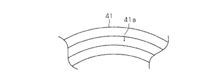
図3は第1環状部材41をアウター側から見たときの平面図である。同図に示すように、第1環状部材41の合わせ面41aには、3つの円錐面が形成されている。一方、第2環状部材42の合わせ面42aには、これらの円錐面とそれぞれ当接する3つの円錐面が形成される。このように合わせ面41a,42aを円錐面からなる凹凸面により形成することにより、合わせ面41aと合わせ面42aとを相対回転可能に係合するとともに、合わせ面41a,42a間の接触面積が合わせ面を平面で形成する場合に比べて大きくなるようにしている。
FIG. 3 is a plan view of the first
また、合わせ面41aと合わせ面42aとの間には、グリース、オイル等の潤滑剤が塗布されている。このように潤滑剤を塗布することで、合わせ面41aと合わせ面42aとの摩擦抵抗を低減し、合わせ面41a,42aが相対回転し易くなるようにしている。また、第1環状部材41は、インナー側の側面41bが駆動軸10の側面16と当接し、第2環状部材42は、アウター側の側面42bが内輪31の側面39と当接している。
Further, a lubricant such as grease or oil is applied between the
このように構成される車輪用転がり軸受装置1において、駆動軸10と内軸20とは以下のように結合される。駆動軸10の小径部12を内軸20の中心孔24に挿入することで、小径部12のスプライン部13と中心孔24のスプライン部25とをスプライン係合させ、駆動軸10と内軸20との回転方向の結合が行われる。また、内輪31のインナー側の側面39と駆動軸10の大径部11のアウター側の側面16との間にワッシャ部材40を介在させて、駆動軸10のねじ部14にナット15を螺合することで駆動軸10を内軸20に対してアウター側に押圧し、駆動軸10と内軸20と内輪31との軸方向の結合が行われる。このようにして駆動軸10と内軸20等とを結合することにより、転がり軸受30の内輪31に適切な予圧を付与するとともに、駆動軸10、内軸20、及び内輪31が一体的に回転するように構成している。
In the wheel rolling
次に、車両が急発進や急旋回するような状況において、内輪31の側面39と駆動軸10の側面16との間に大きなねじりトルクが加わる場合について説明する。内輪31の側面39と駆動軸10の側面16との間にねじりトルクが加わると、内輪31の側面39と第2環状部材42の側面42bとの当接面Aと、第1環状部材41の合わせ面41aと第2環状部材42の合わせ面42aとの合わせ面Bと、第1環状部材41の側面41bと駆動軸10の側面16との当接面Cとにおいて、互いに当接する面が相対運動しようとする。
Next, a case where a large torsional torque is applied between the
このとき、合わせ面Bは、当接面A,Cよりも接触面積が大きいため、ナット15の螺合により発生する面圧が当接面A,Cに発生する面圧よりも低くなり、摩擦抵抗が低い状態となっている。また、合わせ面Bは、潤滑剤が塗布されているため、摩擦抵抗がより低い状態となっている。このため、上記のようなねじりトルクが加わると、合わせ面Bにおいてスティックスリップ現象が発生することになる。スティックスリップ現象が合わせ面Bで発生する場合、合わせ面Bは上述のように摩擦抵抗が低い状態となっているため、スティックスリップ現象により合わせ面Bに蓄積されるエネルギが小さくなり、蓄積されたエネルギの開放により発生する異音が小さくなる。
At this time, since the mating surface B has a larger contact area than the contact surfaces A and C, the surface pressure generated by the screwing of the
このようにして、内輪31の側面39と駆動軸10の側面16との間にワッシャ部材40を介在させると、ワッシャ部材40を介在させない場合に比べて、スティックスリップ現象が発生する面の面圧を下げることができ、摩擦抵抗を低減することができる。さらに、スティックスリップ現象が発生する面に潤滑剤を塗布すると、摩擦抵抗をより一層低減することができる。このため、車輪用転がり軸受装置1において、スティックスリップ現象により発生する異音の音圧レベルを好適に低減することができる。
In this way, when the
上記第1実施形態の車輪用転がり軸受装置1によれば、以下のような効果を得ることができる。
(1)第1実施形態では、内輪31の側面39と駆動軸10の側面16との間にはワッシャ部材40が介在され、ワッシャ部材40は、第1環状部材41と第2環状部材42との合わせ面Bが、互いに相対回転可能に係合する凹凸面により形成される。このため、合わせ面Bにおける接触面積を、合わせ面を平面で形成する場合や、内輪31の側面39と駆動軸10の側面16とを直接当接させる場合に比べて、大きくすることができる。従って、ナット15の螺合により合わせ面Bに発生する面圧を小さくすることができるため、合わせ面Bの摩擦抵抗を低減することができる。これにより、内輪31の側面39と駆動軸10の側面16との間にねじりトルクが作用したときに、スティックスリップ現象により蓄積されるエネルギを小さくすることができ、そのエネルギの開放により発生する異音も小さくすることができる。このため、車両が急発進や急旋回するような状況において発生する異音の音圧レベルを低減することができる。
According to the wheel rolling
(1) In the first embodiment, the
(2)第1実施形態では、ワッシャ部材40の第1環状部材41と第2環状部材42との合わせ面Bには、潤滑剤が塗布されているため、合わせ面間の摩擦抵抗を低減させることができる。このため、内輪31の側面39と駆動軸10の側面16との間にねじりトルクが作用したときに、スティックスリップ現象により合わせ面に蓄積されるエネルギを小さくして、そのエネルギの開放により発生する異音の音圧レベルをより一層低減することができる。
(2) In the first embodiment, since the lubricant is applied to the mating surface B of the first
(第2実施形態)
次に、図4を参照して、本発明に係る車輪用転がり軸受装置を具体化した第2実施形態について説明する。第2実施形態の車輪用転がり軸受装置2では、内輪31の内軸20に対する固定を内軸20の軸端かしめにより行っている点が、第1実施形態の車輪用転がり軸受装置1と相違する。なお、以下に説明する実施形態において、第1実施形態と同一構成については同一符号を付し、その重複する説明を省略又は簡略する。
(Second Embodiment)
Next, with reference to FIG. 4, 2nd Embodiment which actualized the rolling bearing device for wheels which concerns on this invention is described. The wheel rolling bearing device 2 of the second embodiment is different from the wheel rolling
図4は車輪用転がり軸受装置2の縦断面図である。同図に示すように、転がり軸受30の内輪31は、軸端かしめにより形成されたかしめ部28によって固定されている。軸端かしめは、内輪31の内周面36を軸部21の外周面26と嵌合させて、内輪31のアウター側の側面37を軸部21の段差部側面27と当接させた状態で、軸部21の軸端のインナー側からかしめ治具を押し付けることで行われる。そして、軸端を径方向外方に塑性変形させてかしめ部28を形成し、内輪31をアウター側に押し付けるように固定する。これにより、内輪31を内軸20に対して確実に固定するとともに、内輪31に適切な予圧を与えている。
FIG. 4 is a longitudinal sectional view of the wheel rolling bearing device 2. As shown in the figure, the
ワッシャ部材40は、環状に形成されており、かしめ部28のインナー側の側面29と、駆動軸10の大径部11のアウター側の側面16との間に介在されて、その内周面が駆動軸10の小径部12の基部に形成された外周面17に遊嵌している。ワッシャ部材40は、第1実施形態と同様に、第1環状部材41と第2環状部材42とから構成され、合わせ面Bが互いに相対回転可能に係合する凹凸面により形成されている。また、合わせ面Bには潤滑剤が塗布されている。
The
そして、駆動軸10と内軸20とは以下のように結合されている。駆動軸10の小径部12を内軸20の中心孔24に挿入することで、小径部12のスプライン部13と中心孔24のスプライン部25とをスプライン係合させ、駆動軸10と内軸20との回転方向の結合が行われる。また、かしめ部28のインナー側の側面29と駆動軸10の大径部11のアウター側の側面16との間にワッシャ部材40を介在させて、駆動軸10のねじ部14にナット15を螺合することで駆動軸10を内軸20に対してアウター側に押圧し、駆動軸10と内軸20との軸方向の結合が行われる。このようにして駆動軸10と内軸20とを結合することにより、駆動軸10、内軸20、及び内輪31が一体的に回転するように構成している。
The
以上のように構成された車輪用転がり軸受装置2において、車両の急発進時や急旋回時に、かしめ部28の側面29と駆動軸10の側面16との間に大きなねじりトルクが加わる場合、ワッシャ部材40は第1実施形態と同様に機能する。すなわち、ワッシャ部材40の合わせ面Bは摩擦抵抗が低い状態となっているため、合わせ面Bにおいてスティックスリップ現象が発生するようになる。そして、摩擦抵抗の低い合わせ面Bでスティックスリップ現象が発生すると、合わせ面Bに蓄積されるエネルギが小さくなり、蓄積されたエネルギの開放により発生する異音を小さくすることができる。
In the wheel rolling bearing device 2 configured as described above, when a large torsional torque is applied between the
このようにして、かしめ部28の側面29と駆動軸10の側面16との間にワッシャ部材40を介在させると、ワッシャ部材40を介在させない場合に比べて、スティックスリップ現象が発生する面の面圧を下げることができ、摩擦抵抗を低減することができる。さらに、スティックスリップ現象が発生する面に潤滑剤を塗布すると、摩擦抵抗をより一層低減することができる。このため、車輪用転がり軸受装置2において、スティックスリップ現象により発生する異音の音圧レベルを好適に低減することができ、第1実施形態の効果(1),(2)と同様の効果を得ることができる。
In this way, when the
なお、上記実施形態は以下のように変更してもよい。
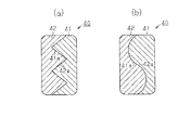
・上記実施形態では、ワッシャ部材40は、第1環状部材41の合わせ面41a及び第2環状部材42の合わせ面42aに3つの円錐面を形成し、互いに相対回転可能に係合するように構成しているが、2つの円錐面、又は4つ以上の円錐面を合わせ面41a,42aに形成して、互いに相対回転可能に係合するように構成してもよい。一例として、図5(a)に5つの円錐面で合わせ面41a,42aを構成したときの断面図を示す。
In addition, you may change the said embodiment as follows.
In the above embodiment, the
・上記実施形態では、ワッシャ部材40は、第1環状部材41の合わせ面41a及び第2環状部材42の合わせ面42aを円錐面により構成しているが、曲面等の円錐面以外の面により構成してもよいし、曲面と円錐面とにより構成してもよい。一例として、図5(b)に曲面で合わせ面41a,42aを構成したときの断面図を示す。図5の各形態に示すように合わせ面41a,42aを構成しても、合わせ面Bの接触面積を大きくして面圧を下げることができ、合わせ面Bの摩擦抵抗を低減することができる。
In the above embodiment, the
・上記実施形態では、ワッシャ部材40は、第1環状部材41と第2環状部材42との2つの環状部材により構成されているが、3つ以上の環状部材によりワッシャ部材を構成してもよい。図6(a),(b)に3つの環状部材51,52,53でワッシャ部材50を構成したときの断面図を示す。このようにすると、スティックスリップ現象により発生する合わせ面の相対運動を、環状部材51と環状部材52との合わせ面Dにおける相対運動と、環状部材52と環状部材53との合わせ面Eにおける相対運動とに分散させることができるため、相対運動により発生する異音を低減することができる。
In the above embodiment, the
・上記実施形態では、合わせ面Bの接触面積を大きくして、スティックスリップ現象が合わせ面Bで発生するように構成しているが、ワッシャ部材40と駆動軸10との当接面、及びワッシャ部材40と内輪31又はかしめ部28との当接面の摩擦係数を大きくして、合わせ面Bで確実にスティックスリップ現象が発生するように構成してもよい。
In the above embodiment, the contact area of the mating surface B is increased so that the stick-slip phenomenon occurs on the mating surface B. However, the contact surface between the
・上記実施形態では、軸部21のフランジ部22側の外周に、アウター側の玉34の軌道面である第2軌道21aを形成しているが、内輪31のアウター側に個別の内輪部材を設けるように構成し、この内輪に第2軌道21aを形成するようにしてもよい。
In the above embodiment, the
・上記実施形態では、転がり軸受30として複列の玉軸受を用いているが、複列の円錐ころ軸受を用いてもよい。
In the above embodiment, a double row ball bearing is used as the rolling
1,2…車輪用転がり軸受装置、10…駆動軸、11…大径部、12…小径部、15…ナット、20…内軸、21…軸部、28…かしめ部、30…転がり軸受、31…内輪、32…外輪、40…ワッシャ部材、41…第1環状部材、42…第2環状部材。
DESCRIPTION OF
Claims (3)
前記小径部の外周にスプラインを介して取り付けられる内軸と、
内軸の外周にインナー側から取り付けられる転がり軸受の内輪とを備え、
駆動軸を内軸に対してアウター側に押圧し、内輪のインナー側の側面と前記大径部のアウター側の側面との間に押圧力を付与することで、駆動軸、内軸、及び内輪を結合するようにした車輪用転がり軸受装置において、
前記押圧力が付与される各側面の間には、複数の環状部材を軸方向に重ね合せたワッシャ部材が介在されており、
前記ワッシャ部材は、前記環状部材の少なくとも一対の合わせ面が、互いに相対回転可能に係合する凹凸面により形成される
ことを特徴とする車輪用転がり軸受装置。 A drive shaft having a large diameter portion on the inner side and a small diameter portion on the outer side;
An inner shaft attached to the outer periphery of the small diameter portion via a spline;
An inner ring of a rolling bearing attached to the outer periphery of the inner shaft from the inner side,
The drive shaft is pressed to the outer side with respect to the inner shaft, and a pressing force is applied between the inner side surface of the inner ring and the outer side surface of the large-diameter portion, so that the drive shaft, the inner shaft, and the inner ring In the rolling bearing device for wheels,
Between each side surface to which the pressing force is applied, a washer member in which a plurality of annular members are overlapped in the axial direction is interposed,
The rolling bearing device for a wheel according to claim 1, wherein the washer member includes at least a pair of mating surfaces of the annular member that are engaged with each other so as to be relatively rotatable.
前記小径部の外周にスプラインを介して取り付けられる内軸と、
内軸のインナー側軸端をかしめることにより内軸に固定される転がり軸受の内輪とを備え、
駆動軸を内軸に対してアウター側に押圧し、前記かしめにより形成されるかしめ部のインナー側の側面と前記大径部のアウター側の側面との間に押圧力を付与することで、駆動軸及び内軸を結合するようにした車輪用転がり軸受装置において、
前記押圧力が付与される各側面の間には、複数の環状部材を軸方向に重ね合せたワッシャ部材が介在されており、
前記ワッシャ部材は、前記環状部材の少なくとも一対の合わせ面が、互いに相対回転可能に係合する凹凸面により形成される
ことを特徴とする車輪用転がり軸受装置。 A drive shaft having a large diameter portion on the inner side and a small diameter portion on the outer side;
An inner shaft attached to the outer periphery of the small diameter portion via a spline;
An inner ring of a rolling bearing fixed to the inner shaft by caulking the inner side shaft end of the inner shaft;
Driving the drive shaft by pressing the drive shaft toward the outer side and applying a pressing force between the inner side surface of the caulking portion formed by the caulking and the outer side surface of the large diameter portion. In a rolling bearing device for a wheel in which a shaft and an inner shaft are coupled,
Between each side surface to which the pressing force is applied, a washer member in which a plurality of annular members are overlapped in the axial direction is interposed,
The rolling bearing device for a wheel according to claim 1, wherein the washer member includes at least a pair of mating surfaces of the annular member that are engaged with each other so as to be relatively rotatable.
前記合わせ面の凹凸面間には、潤滑剤が塗布されている
ことを特徴とする車輪用転がり軸受装置。 In the rolling bearing device for wheels according to claim 1 or 2,
A rolling bearing device for a wheel, wherein a lubricant is applied between the uneven surfaces of the mating surfaces.
Priority Applications (1)
| Application Number | Priority Date | Filing Date | Title |
|---|---|---|---|
| JP2007035062A JP2008196665A (en) | 2007-02-15 | 2007-02-15 | Wheel rolling bearing device |
Applications Claiming Priority (1)
| Application Number | Priority Date | Filing Date | Title |
|---|---|---|---|
| JP2007035062A JP2008196665A (en) | 2007-02-15 | 2007-02-15 | Wheel rolling bearing device |
Publications (1)
| Publication Number | Publication Date |
|---|---|
| JP2008196665A true JP2008196665A (en) | 2008-08-28 |
Family
ID=39755792
Family Applications (1)
| Application Number | Title | Priority Date | Filing Date |
|---|---|---|---|
| JP2007035062A Pending JP2008196665A (en) | 2007-02-15 | 2007-02-15 | Wheel rolling bearing device |
Country Status (1)
| Country | Link |
|---|---|
| JP (1) | JP2008196665A (en) |
Cited By (1)
| Publication number | Priority date | Publication date | Assignee | Title |
|---|---|---|---|---|
| KR20160049903A (en) * | 2014-10-28 | 2016-05-10 | 주식회사 일진글로벌 | Wheel bearing and wheel bearing assembly using the same |
-
2007
- 2007-02-15 JP JP2007035062A patent/JP2008196665A/en active Pending
Cited By (2)
| Publication number | Priority date | Publication date | Assignee | Title |
|---|---|---|---|---|
| KR20160049903A (en) * | 2014-10-28 | 2016-05-10 | 주식회사 일진글로벌 | Wheel bearing and wheel bearing assembly using the same |
| KR101689839B1 (en) * | 2014-10-28 | 2016-12-26 | 주식회사 일진글로벌 | Wheel bearing and wheel bearing assembly using the same |
Similar Documents
| Publication | Publication Date | Title |
|---|---|---|
| JP4315819B2 (en) | Drive wheel bearing device | |
| JP5079270B2 (en) | Wheel bearing unit | |
| JP2003097588A (en) | Hub unit for automobile driving wheel | |
| JP2008002579A (en) | Bearing unit for drive wheel | |
| JP2008002578A (en) | Bearing unit for drive wheel | |
| JP2008001243A (en) | Bearing unit for driving wheel | |
| JP2006248373A (en) | Bearing device for wheel | |
| WO2009081554A1 (en) | Bearing device for wheel | |
| JP2010047059A (en) | Wheel bearing device and axle module | |
| JP5143455B2 (en) | Drive wheel bearing device | |
| JP4020045B2 (en) | Rolling bearing device | |
| JP2008196665A (en) | Wheel rolling bearing device | |
| JP2008002582A (en) | Bearing unit for drive wheel | |
| JP2007069704A (en) | Bearing device for driving wheel | |
| JP2008247274A (en) | Wheel bearing device | |
| JP2009234289A (en) | Bearing device for drive wheel | |
| JP2008082348A (en) | Wheel rolling bearing device | |
| JP5143442B2 (en) | Drive wheel bearing device | |
| JP2008001237A (en) | Bearing unit for driving wheel | |
| JP4655016B2 (en) | Rolling bearing device for wheels | |
| JP2018154238A (en) | Bearing device for wheel | |
| JP2009090969A (en) | Bearing device for wheel | |
| JP4481966B2 (en) | Wheel bearing device for driving wheel | |
| JP2007331711A (en) | Driving wheel axle structure and rolling bearing | |
| JP2017047716A (en) | Bearing device for wheel |