JP2008193262A - Data communication system, and data communication method - Google Patents
Data communication system, and data communication method Download PDFInfo
- Publication number
- JP2008193262A JP2008193262A JP2007023463A JP2007023463A JP2008193262A JP 2008193262 A JP2008193262 A JP 2008193262A JP 2007023463 A JP2007023463 A JP 2007023463A JP 2007023463 A JP2007023463 A JP 2007023463A JP 2008193262 A JP2008193262 A JP 2008193262A
- Authority
- JP
- Japan
- Prior art keywords
- data
- transmission
- address
- transmission right
- processing device
- Prior art date
- Legal status (The legal status is an assumption and is not a legal conclusion. Google has not performed a legal analysis and makes no representation as to the accuracy of the status listed.)
- Granted
Links
- 238000004891 communication Methods 0.000 title claims abstract description 114
- 238000000034 method Methods 0.000 title claims description 42
- 230000005540 biological transmission Effects 0.000 claims abstract description 244
- 238000012545 processing Methods 0.000 claims description 201
- 238000012937 correction Methods 0.000 claims description 62
- 230000008569 process Effects 0.000 claims description 26
- 238000007726 management method Methods 0.000 claims description 23
- 238000012546 transfer Methods 0.000 claims description 19
- 238000001514 detection method Methods 0.000 claims description 11
- 230000004044 response Effects 0.000 claims description 3
- 230000015654 memory Effects 0.000 description 83
- 230000006870 function Effects 0.000 description 5
- 230000008859 change Effects 0.000 description 3
- 238000012790 confirmation Methods 0.000 description 3
- 230000007423 decrease Effects 0.000 description 2
- 238000010586 diagram Methods 0.000 description 2
- 230000006872 improvement Effects 0.000 description 2
- 238000007689 inspection Methods 0.000 description 2
- 101100172132 Mus musculus Eif3a gene Proteins 0.000 description 1
- 238000007796 conventional method Methods 0.000 description 1
- 230000001934 delay Effects 0.000 description 1
- 230000003111 delayed effect Effects 0.000 description 1
- 230000007257 malfunction Effects 0.000 description 1
- 230000009467 reduction Effects 0.000 description 1
- 230000007704 transition Effects 0.000 description 1
Images


Classifications
-
- G—PHYSICS
- G06—COMPUTING; CALCULATING OR COUNTING
- G06F—ELECTRIC DIGITAL DATA PROCESSING
- G06F13/00—Interconnection of, or transfer of information or other signals between, memories, input/output devices or central processing units
- G06F13/14—Handling requests for interconnection or transfer
- G06F13/36—Handling requests for interconnection or transfer for access to common bus or bus system
- G06F13/368—Handling requests for interconnection or transfer for access to common bus or bus system with decentralised access control
- G06F13/37—Handling requests for interconnection or transfer for access to common bus or bus system with decentralised access control using a physical-position-dependent priority, e.g. daisy chain, round robin or token passing
-
- H—ELECTRICITY
- H04—ELECTRIC COMMUNICATION TECHNIQUE
- H04L—TRANSMISSION OF DIGITAL INFORMATION, e.g. TELEGRAPHIC COMMUNICATION
- H04L1/00—Arrangements for detecting or preventing errors in the information received
- H04L1/12—Arrangements for detecting or preventing errors in the information received by using return channel
- H04L1/16—Arrangements for detecting or preventing errors in the information received by using return channel in which the return channel carries supervisory signals, e.g. repetition request signals
- H04L1/18—Automatic repetition systems, e.g. Van Duuren systems
- H04L1/1829—Arrangements specially adapted for the receiver end
Landscapes
- Engineering & Computer Science (AREA)
- Theoretical Computer Science (AREA)
- Physics & Mathematics (AREA)
- General Engineering & Computer Science (AREA)
- General Physics & Mathematics (AREA)
- Computer Networks & Wireless Communication (AREA)
- Signal Processing (AREA)
- Information Transfer Systems (AREA)
- Small-Scale Networks (AREA)
- Communication Control (AREA)
Abstract
Description
本発明は、シリアルバスで接続された複数の分散コントローラ間において、リアルタイムにメモリデータを共有するためのデータ通信システム及びデータ通信方法に関する。 The present invention relates to a data communication system and a data communication method for sharing memory data in real time between a plurality of distributed controllers connected by a serial bus.
ロボットなどのように、センサやアクチュエータなど多数のデバイスが実装され、それらを使った複雑な制御を必要とする組込み制御機器では、それら複数のデバイスをいくつかの分散コントローラに分割して管理し、相互に通信しながら協調制御する構成が多く採用されている。こうした分散制御型の構成が採用される理由はいくつかあるが、組込み制御として特に重要なのは、配線集中の緩和による機器の小型化と、配線距離の短縮に伴うノイズ問題の改善及び信頼性向上である。 Many embedded devices such as robots and sensors and actuators are mounted, and in embedded control equipment that requires complex control using them, these multiple devices are divided into several distributed controllers and managed, Many configurations that perform cooperative control while communicating with each other are employed. There are several reasons why such a distributed control type configuration is adopted, but what is particularly important as embedded control is the downsizing of equipment by reducing wiring concentration, the improvement of noise problems and the improvement of reliability due to the reduction of wiring distance. is there.
多数のデバイスを単一のコントローラで制御する構成では、各デバイスと接続するための信号線をコントローラ部分に集中配線しなければならないため、コントローラの周辺に多数の信号線を集中して取り回すための広い空きスペースを確保しなければならない。更に、太く束ねた配線束を機器末端部から中央のコントローラ部まで引き回すための配線スペースが必要になる。そのため、集中制御型の構成では、機器の小型化が難しい。 In a configuration in which a large number of devices are controlled by a single controller, the signal lines that connect to each device must be centrally wired in the controller, so that many signal lines are concentrated around the controller. A large free space must be secured. Furthermore, a wiring space is required to route the thickly bundled wiring bundle from the terminal end to the central controller. Therefore, it is difficult to reduce the size of the device with the central control type configuration.
また、アクチュエータ駆動線のような大電流配線からは、周囲に大きなノイズを放射する場合がある。そのため、センサ等の微小アナログ信号線とアクチュエータ駆動線のような大電流配線を機器末端部からコントローラ部まで長距離配線すると、大電流配線から放射されたノイズがアナログ信号線に混入し誤動作の要因となる場合があり、機器の信頼性が低下する。 In addition, a large current wiring such as an actuator drive line may radiate a large noise around. Therefore, if a large current wiring such as a small analog signal line such as a sensor and an actuator drive line is wired over a long distance from the device end to the controller, noise radiated from the large current wiring will be mixed into the analog signal line and cause malfunctions. The reliability of the equipment is reduced.
こうした理由から、機器の部位毎にコントローラを分散し、特定の部位に属するデバイスは、デバイス近くに設置したコントローラに配線して管理する構成が採用されている。また、複数の部位にまたがったデバイスの情報を使って協調制御する際は、各コントローラ間を互いに接続したシリアルバスを介して相互にデータを受け渡す方法が多く採られている。このような分散コントローラシステムでは、コントローラ相互のデータ共有をリアルタイムで実現する必要があるため、どういう方法でデータ通信を行うかが重要である。 For these reasons, a configuration is adopted in which controllers are distributed for each part of equipment, and devices belonging to a specific part are managed by wiring to a controller installed near the device. Further, when cooperative control is performed using information on devices extending over a plurality of parts, many methods are used to exchange data with each other via serial buses connecting the controllers. In such a distributed controller system, since it is necessary to realize data sharing between controllers in real time, it is important how to perform data communication.
現在、最も普及している通信方式の一つに、イーサネット(登録商標)(商標:Ethernet(登録商標)、IEEE802.3uとして100BASE-TXという規格が標準化されている)などを利用したLAN(Local Area Network)がある。イーサネット(登録商標)は、CSMA/CD(Carrier Sense Multiple Access/Collision Detection)方式を採用しているため、通信データ量が増えるとデータ衝突が多発してバスの利用効率が低下するほか、通信遅れ時間(レイテンシ)のワースト値が予想不能であるという問題がある。このため、イーサネット(登録商標)は、組込み制御用の通信手段としては不適当である。また、データ衝突の問題を解決したLANの通信制御方式の一つにトークンリング(Token Ring、IEEE802.5で標準化された規格)がある。「トークン」と呼ばれる送信権を表すデータがネットワークを流れていて、データを送信したい端末は、トークンを取り込んでデータを送信し、送信終了後、再びトークンをネットワークに流す。これにより、一度に一台の端末のみネットワークを利用するように制御し、データ衝突の問題を解決している。ところが、トークンはある長さを持ったデータ列であり、通信データと同じ線に流れるため、通信路に負担がかかる。更に、データはネットワーク上を順番に伝送されるため、通信レイテンシが大きいという問題がある。 Currently, one of the most popular communication methods is LAN (Local) using Ethernet (registered trademark) (trademark: Ethernet (registered trademark), standardized as 100BASE-TX as IEEE802.3u). Area Network). Ethernet (registered trademark) employs CSMA / CD (Carrier Sense Multiple Access / Collision Detection) method, so if the amount of communication data increases, data collisions occur frequently and the bus utilization efficiency decreases, and communication delays occur. There is a problem that the worst value of time (latency) is unpredictable. For this reason, Ethernet (registered trademark) is not suitable as a communication means for embedded control. One of LAN communication control methods that solves the data collision problem is Token Ring (a standard standardized by IEEE802.5). Data representing a transmission right called a “token” flows through the network, and a terminal that wants to transmit data takes in the token and transmits the data, and after the transmission ends, flows the token through the network again. This solves the data collision problem by controlling so that only one terminal uses the network at a time. However, the token is a data string having a certain length and flows on the same line as the communication data, which places a burden on the communication path. Furthermore, since data is transmitted sequentially over the network, there is a problem that communication latency is large.
また、イーサネット(登録商標)、トークンリング共に、データ受渡し先の指定やデータ送信処理、応答処理やエラー訂正処理などを全てソフトウェアで管理しているため、プロセッサの負担が大きい。そのため、組込み制御機器などのように、機器本体のハードウェアとコントローラなどに組み込むソフトウェアとを同時並行開発する場合は、障害発生時の原因の切り分けが難しい。 In addition, for both Ethernet (registered trademark) and token ring, the specification of data delivery destination, data transmission processing, response processing, error correction processing, and the like are all managed by software, which places a heavy burden on the processor. Therefore, when the hardware of the device main body and the software incorporated in the controller or the like are developed simultaneously in parallel, such as an embedded control device, it is difficult to isolate the cause when a failure occurs.
特許文献1には、上記問題点を解決するために、メモリを搭載した複数のコントローラ(局)をシリアルバスで接続し、各局が保持するメモリデータを周期的に他局のメモリの該当領域に転写するハードウェアを実装することにより、複数局間でメモリデータを共有する複数局メモリデータ共有システムの例についての開示がある。非特許文献1には、複数局メモリデータ共有システムに関する製品実施例についての開示がある。
上記従来の方法では、シリアルバスの通信処理をハード化することでソフトウェアの負担が皆無になり、なおかつメモリデータの転写周期が定まることにより通信レイテンシが明確になる。ところが、複数局間で共有する全メモリデータを周期的にシリアルバス上に送信し、全ての局のメモリデータを一致させる方法のため、ある局のメモリに書き込んだデータを他局のメモリに反映させるための遅れ時間(レイテンシ)は、データを共有するメモリの容量に比例して増大するという問題がある。 In the above-described conventional method, the burden of software is eliminated by making the serial bus communication processing hardware, and the communication latency is clarified by determining the memory data transfer cycle. However, because all memory data shared by multiple stations is periodically transmitted on the serial bus and the memory data of all stations are matched, the data written in the memory of one station is reflected in the memory of other stations. There is a problem that the delay time (latency) for increasing the delay time increases in proportion to the capacity of the memory sharing the data.
本発明はかかる点に鑑みてなされたものであり、(1)共有データ量の多少に影響を受けず通信のワーストレイテンシを小さく実現すること、(2)プロセッサのソフトウェア負担が小さいこと、(3)配線量が少なく、省スペース実装に有利なシリアル接続方式とすること、を同時に実現したデータ通信システムを実現することを目的とする。 The present invention has been made in view of the above points. (1) The communication worst latency is not affected by the amount of shared data, (2) The software load on the processor is small, (3 ) The purpose is to realize a data communication system that simultaneously realizes a serial connection method that is advantageous in space-saving mounting with a small amount of wiring.
本発明は、シリアルバスインタフェースを備えた複数の処理装置を、シリアルバスを介して相互に接続したデータ通信システムであって、各処理装置間を順次接続して、シリアルバスへのデータ送信を許可する送信権の受渡しを行う通信制御線を設け、処理装置には、通信制御線に接続し、送信権の受け渡しを行うと共に、自処理装置内の送信権の状態を管理する送信権管理手段と、自処理装置の送信権が有効の場合はシリアルバスへのデータ送信を開始し、送信権が無効の場合はデータ送信を保留するデータ送信手段と、初期化時に、シリアルバスに接続する複数の処理装置のうち、1つの処理装置の送信権のみを有効とするように、自処理装置の初期状態を設定する状態初期化手段とを備える。 The present invention is a data communication system in which a plurality of processing devices having a serial bus interface are connected to each other via a serial bus, and the processing devices are sequentially connected to allow data transmission to the serial bus. A communication control line for delivering the transmission right to be transmitted, and the processing device is connected to the communication control line to deliver the transmission right and transmit right management means for managing the state of the transmission right in the own processing device; , Start data transmission to the serial bus when the transmission right of the own processing device is valid, and data transmission means for holding the data transmission when the transmission right is invalid, and a plurality of units connected to the serial bus at initialization A state initialization unit is provided for setting the initial state of the processing device so that only the transmission right of one processing device is valid among the processing devices.
本発明によると、シリアルバスで繋がれた複数の処理装置の間に通信制御線を設けて送信権の受渡しを行うことにより、シリアルバスのデータ通信に負担をかけることなく、シリアルバスへのデータ送信タイミングをハード的に制御する手段を提供することができる。これにより、バス利用効率低下の原因となるデータ衝突を回避することができ、データ通信速度が向上すると同時に、通信のワーストレイテンシを小さくすることができる。 According to the present invention, by providing a communication control line between a plurality of processing devices connected by a serial bus and transferring a transmission right, data to the serial bus can be transmitted without imposing a burden on the data communication of the serial bus. A means for controlling transmission timing in hardware can be provided. As a result, it is possible to avoid a data collision that causes a decrease in bus utilization efficiency, thereby improving the data communication speed and reducing the communication worst latency.
また、処理装置にプロセッサおよびプロセッサが読み書きするメモリを追加し、メモリへのデータ書込み時に、シリアルバスを介して接続する全処理装置のメモリへデータ変更を反映させる手段を設けることにより、ソフトウェアを介すことなくメモリデータを自動的に共有化することができる。更に、データを変更する時だけ変更対象のアドレスとデータを送信するため、共有メモリサイズの増加によるレイテンシへの影響が無い。またシリアルバスの利用効率が高く、転送速度が速くなるため、大容量データの転送に好適である。 In addition, a processor and a memory that the processor reads and writes are added to the processing device, and when data is written to the memory, a means for reflecting the data change to the memory of all the processing devices connected via the serial bus is provided. The memory data can be automatically shared without doing so. Furthermore, since the address and data to be changed are transmitted only when the data is changed, there is no influence on the latency due to the increase in the shared memory size. In addition, the use efficiency of the serial bus is high and the transfer speed is high, so that it is suitable for transferring a large amount of data.
更に、本発明において、1つの処理装置が1回に変更できるデータサイズに制約を設けた(例えば1データ)とすると、シリアルバスに接続する各処理装置にはデータ変更の機会が均等に訪れる。1つの処理装置で大量のデータ変更を行う場合は、待ちが発生してレイテンシが増加する場合があるが、増加するレイテンシのワースト値は、その処理装置が行おうとしている処理に関する情報だけに基づいて予測できる。そのため、1データだけ変更するよう制約を設けた場合のワーストレイテンシは、シリアルバスに接続した装置台数だけに依存することになるため、算出可能である。 Further, in the present invention, assuming that a data size that can be changed at one time by one processing device is provided (for example, one data), the processing devices connected to the serial bus have equal opportunities to change data. When a large amount of data is changed by one processing device, there is a case where a wait occurs and the latency increases, but the worst value of the increased latency is based only on information related to the processing to be performed by the processing device. Can be predicted. For this reason, the worst latency in the case where a restriction is set so that only one data is changed depends on only the number of devices connected to the serial bus, and can be calculated.
また、本発明によると、通信エラーの検出と訂正、および再送機能をハードウェアで実現することができる。本発明では、データを変更した処理装置がシリアルバスにデータを送信すると、送信した処理装置以外の全ての処理装置が同時にデータを受信する。データを受信した処理装置は、個別にエラー検出/訂正を実施するが、訂正しきれないエラーを検出した場合は、送信権が巡ってきた時に再送要求コマンドを送信する。一方、正常にデータを受信できた処理装置は全て正常なデータを保持しているので、再送要求コマンドが送信された後、最初に送信権が巡ってきた処理装置(変更データを送信した装置でなくて良い)が再送を実施することができる。また、受信データが訂正不能の場合であっても、自処理装置に送信権が巡ってくる以前に、別の処理装置により該データの再送要求が送出された場合は、同じデータに対して重複して再送要求することはせず、他の処理装置から再送データが送られるのを待つ。これにより、本来であればソフトウェアの負担となるエラー検出/訂正処理や再送処理を、全てハードウェアに任せることができる。また、エラー検出/訂正処理や再送処理は処理装置が個別に行うが、シリアルバスに接続する全ての処理装置が連携して行うため、再送処理などの重複がなく、迅速に処理することができる。また、データ再送によるワーストレイテンシの増加量も明確に算出することが可能となる。 In addition, according to the present invention, communication error detection and correction, and a retransmission function can be realized by hardware. In the present invention, when the processing device whose data has been changed transmits data to the serial bus, all the processing devices other than the transmitting processing device simultaneously receive the data. The processing apparatus that has received the data individually performs error detection / correction, but when an error that cannot be corrected is detected, a retransmission request command is transmitted when the transmission right is reached. On the other hand, since all the processing devices that have successfully received data hold normal data, after the retransmission request command is transmitted, the first processing device that has received the transmission right (the device that transmitted the change data). Can be retransmitted). Even if the received data cannot be corrected, if a retransmission request for the data is sent out by another processing device before the transmission right reaches the own processing device, the same data is duplicated. Then, it does not request retransmission and waits for retransmission data from another processing apparatus. As a result, all error detection / correction processing and retransmission processing that would otherwise be a burden on the software can be left to the hardware. In addition, error detection / correction processing and retransmission processing are individually performed by the processing device, but since all processing devices connected to the serial bus perform in cooperation, there is no duplication of retransmission processing and the like, and processing can be performed quickly. . Further, it is possible to clearly calculate the amount of increase in worst latency due to data retransmission.
以下、本発明の一実施の形態を、添付図面を参照して説明する。 Hereinafter, an embodiment of the present invention will be described with reference to the accompanying drawings.
図1に、本例のデータ通信システムの構成例を示す。本例は、複数の処理装置100が、シリアルバスインタフェース(I/F)103を介してシリアルバス101に接続し、各処理装置100の間は、シリアルバス101のデータ送信権の受け渡しを行う通信制御線102により順次つないで構成する。図1では、通信制御線102の端部は開放状態となっているが、開放部の通信制御線を互いに接続し、リング状として構成することも可能である。
FIG. 1 shows a configuration example of the data communication system of this example. In this example, a plurality of
次に、図1を参照して処理装置100の構成について説明する。なお、シリアルバス101に接続する処理装置はすべて同じ構成であるため、1つの処理装置の構成を説明し、他の処理装置の説明は省略する。処理装置100は、シリアルバス101に接続するためのシリアルバスI/F103と、通信制御線102に接続し、送信権の受け渡しを行うと共に、自処理装置内の送信権の状態を管理する送信権管理手段である送信権管理回路105と、初期化時に自処理装置の送信権の初期状態を設定する状態初期化手段106と、シリアルバスI/F103を介してデータを送信するデータ送信手段であるデータ送信回路104と、シリアルバスI/F103を介してデータを受信するデータ受信手段であるデータ受信回路110と、データを格納する記憶手段であるメモリ107と、メモリ107へのアクセス要求を出す処理手段であるプロセッサ108と、プロセッサ108からのアクセス要求を受け、メモリ107へのデータの入出力を行うメモリインタフェース(I/F)109から構成する。
Next, the configuration of the
次に、本例により、分散型メモリデータ共有システムを構成した場合のメモリデータの共有処理の動作例について説明する。本例を適用して分散型メモリデータ共有システムを構成した場合、シリアルバスに接続する全ての処理装置に搭載するメモリは、すべて同じ内容になる。また、全ての処理装置は、メモリの全領域を読み書きすることが可能であり、メモリの内容を変更した場合は、本例の通信処理により他の処理装置内のメモリへ変更内容を反映する。 Next, an operation example of memory data sharing processing when a distributed memory data sharing system is configured according to this example will be described. When a distributed memory data sharing system is configured by applying this example, all the memories mounted on all processing devices connected to the serial bus have the same contents. Further, all the processing devices can read and write the entire area of the memory, and when the contents of the memory are changed, the changed contents are reflected to the memories in the other processing devices by the communication processing of this example.
まず、プロセッサ108が、メモリ107のデータを読み出す場合の処理について説明する。プロセッサ108が、メモリ107のデータを読み出す際は、メモリI/F109に対して読み出したいメモリのアドレスを指定し、データの読み出し要求を出す。メモリI/F109は、指定されたアドレスのデータをメモリ107から読み出し、読み出したデータをプロセッサ108に渡す。
First, processing when the processor 108 reads data from the
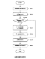
次に、図2を参照して、プロセッサ108が、メモリ107へデータを書き込む場合の処理について説明する。図2は、プロセッサ108がメモリ107へデータを書き込む場合の、メモリへのデータ書き込み処理例を示すフローチャートである。
Next, processing when the processor 108 writes data to the
プロセッサ108が、メモリ107へデータを書き込む際は、まず、メモリI/F109に対して書き込みたいデータとそのアドレスを指定し、データの書き込み要求を出す(ステップS201)。メモリI/F109は、メモリ107の指定されたアドレスへデータを書き込み(ステップS202)、メモリ107へ書き込んだアドレスとデータをデータ送信回路104に渡し、シリアルバス101への送信を要求する(ステップS203)。データ送信回路104は、メモリI/F109からアドレスとデータを受け取ると、送信権管理回路105が保持する自処理装置のシリアルバス送信権の状態を判定し(ステップS204)、送信権が有効である場合は、シリアルバスI/F103にアドレスとデータを渡し、データ送信を要求する(ステップS205)。シリアルバスI/F103は、データ送信回路104から送信要求を受けると、シリアルバス101へデータを送信する(ステップS206)。ステップS204の判定の結果、送信権が無効である場合は、シリアルバス101への送信を一時保留する(ステップS207)。送信を保留した場合は、送信権が有効になった時点で、送信を開始する。なお、送信権の状態を管理する方法と、保留した送信データの送信方法については後述する。
When writing data to the
次に、データの受信処理について説明する。シリアルバス101に接続する処理装置100からデータが送信されると、シリアルバス101に接続する他の全ての処理装置がそのデータを受信する。ある処理装置から送信されたデータは、シリアルバス101を介して他の処理装置100のシリアルバスI/F103へ入力され、データ受信回路110へ受け渡される。データ受信回路110は、他の処理装置100が送信したアドレスとデータをシリアルバスI/F103から受け取り、そのデータを基にメモリI/F109にメモリ107へのデータの書き込みを指示する。メモリI/F109は、メモリ107の指定されたアドレスへデータを書き込む。
Next, data reception processing will be described. When data is transmitted from the
これらの動作により、ある処理装置のプロセッサ108が変更したメモリデータは、その都度シリアルバス101に接続された他の全処理装置のメモリに反映され、変更データを共有することができる。
Through these operations, the memory data changed by the processor 108 of a certain processing device is reflected in the memories of all other processing devices connected to the
次に、送信権管理回路105による送信権の管理方法について説明する。送信権管理回路105は、隣接する両隣の処理装置内の送信権管理回路105とそれぞれ双方向の通信制御線102でつながっているため、送信権管理回路105には、通信制御線102が2本接続することになる。送信権管理回路105は、通信制御線102を介して送信権受け渡し信号のやりとりをすることにより、順番に送信権を受け渡していく。
Next, a transmission right management method by the transmission
最初に、送信権管理回路105は、状態初期化手段106の働きにより、同じシリアルバス101に接続する複数の処理装置100の中で、1台だけシリアルバス送信権が有効になるように初期化される。初期化後は、送信権が有効となった処理装置から順番に送信権受け渡し信号を受け渡していく。
First, the transmission
状態初期化手段106の処理としては、例えば通信制御線102をリング状に接続している場合、予め任意の1台の処理装置の送信権を有効とするような送信権の初期値をメモリなどの記憶装置へ設定しておき、状態初期化手段106はその初期値を参照して初期状態を設定するように処理してもよい。また、通信制御線102がリング状ではなく、端部の処理装置では一方の通信制御線が開放状態となっている場合、状態初期化手段106では、通信制御線が開放状態であるかを検出し、2つある通信制御線のうち、第1の通信制御線が開放状態であった場合は、初期化時の送信権の状態を有効とし、第1の通信制御線が開放状態でなかった場合は、初期化時の送信権の状態を無効とするように初期状態を設定してもよい。このように設定することで、初期化時に1台の処理装置のみ送信権を有効にすることができる。
As processing of the
次に、図3を参照して、初期化後の送信権の管理方法と、保留した送信データの送信方法について説明する。図3は、送信権管理回路105の送信権管理処理例を示すフローチャートである。
Next, a transmission right management method after initialization and a transmission method for suspended transmission data will be described with reference to FIG. FIG. 3 is a flowchart showing a transmission right management process example of the transmission
まず、送信権管理回路105は、第1の通信制御線102に接続する隣接処理装置から送信権受け渡し信号を受け取り(ステップS301)、自処理装置の送信権の状態を有効とする(ステップS302)。送信権が有効となった送信権管理回路105は、データ送信回路104の状態を参照して送信保留データがあるかを判定し(ステップS303)、送信が保留されているデータがある場合は、データ送信回路104へ保留中のデータの送信開始を指示し(ステップS304)、データの送信完了を待つ(ステップS305)。データ送信完了後、送信権を無効化し(ステップS306)、第2の通信制御線102に接続する隣接処理装置へ送信権受け渡し信号を送出する(ステップS307)。ステップS303の送信保留データ有無の判定の結果、送信保留データが無い場合は、すぐに自処理装置の送信権を無効化し(ステップS306)、送信権受け渡し信号を送出する(ステップS307)。
First, the transmission
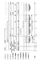
本例によるデータ通信時、シリアルバス101と通信制御線102に流れる信号のタイミング例を図4に示す。ここでは、シリアルバス101上に3つの処理装置(A〜C)が接続しているものとし、各処理装置のプロセッサ108をプロセッサA〜Cと呼ぶ。また、各処理装置間を接続する通信制御線は、リング状ではなく、端部の処理装置、ここでは処理装置AとCは、通信制御線の片方が開放状態となっている例を示す。
FIG. 4 shows a timing example of signals flowing through the
図中の波形(1)〜(3)は、プロセッサA〜Cのメモリアクセスタイミングを示し、“RD”はメモリデータの読み出し、“WT”はメモリへのデータ書き込みを表している。(4)、(5)は、処理装置A−B間とB−C間の通信制御線の信号の動きを示している。(4)の最初の信号は、処理装置AからBへ送信権受け渡し信号を送出したことを表し、(5)の最初の信号は、処理装置BからCへ送信権受け渡し信号を送出したことを表している。また、(6)は、シリアルバス送信権が有効となっている処理装置の遷移状況であり、(4)、(5)で示される送信権受け渡し信号の送出に伴って、送信権が処理装置A→B→Cの順番に受け渡されていることが分かる。(7)〜(9)は、処理装置A〜Cがそれぞれシリアルバス101に出力する信号を、(10)は(7)〜(9)を合成したもの、すなわちシリアルバス101に流れるデータを示す。(11)は、時間を表す。
Waveforms (1) to (3) in the figure indicate the memory access timings of the processors A to C, “RD” indicates reading of memory data, and “WT” indicates writing of data to the memory. (4) and (5) show the movement of signals on the communication control line between the processing apparatuses A and B and B and C. The first signal in (4) indicates that the transmission right transfer signal is sent from the processing apparatuses A to B, and the first signal in (5) indicates that the transmission right transfer signal is sent from the processing apparatuses B to C. Represents. (6) is a transition state of the processing device in which the serial bus transmission right is valid. The transmission right is transmitted to the processing device along with the transmission of the transmission right delivery signal shown in (4) and (5). It can be seen that they are delivered in the order of A → B → C. (7) to (9) indicate signals output from the processing devices A to C to the
時間t1〜t2では、波形(1)〜(3)の最初の部分に示すように、プロセッサAとプロセッサCのリードアクセスタイミングが重なっているが、リードアクセスはそれぞれの処理装置内で完結する構造となっているため、互いに干渉は起きない。またこの時、どの処理装置もシリアルバス101に送信するべきデータを持っていないため、バス送信権はA→B→C→A→B→Cと待ち時間無しで速やかに巡回している。
At time t1 to t2, as shown in the first part of waveforms (1) to (3), the read access timings of processor A and processor C overlap, but the read access is completed within each processing device. Therefore, interference does not occur. At this time, since no processing device has data to be transmitted to the
なおこの実施例では、処理装置AがA−B間の送信権受け渡し信号を出力することでA→Bに、処理装置BがB−C間の送信権受け渡し信号を出力することでB→Cに送信権が移動するが、処理装置Cは通信制御線の片方が開放状態となっていて、隣接する処理装置が存在しないため、B−C間の送信権受け渡し信号を出力することで、逆方向(C→B方向)に送信権を移動する。送信権を逆方向へ移動する際、途中にある処理装置(B)は自処理装置の送信権は有効とせず、反対側に隣接する処理装置へ送信権受け渡し信号を送出し、他方の端部に位置する処理装置(A)のところまで送信権を戻す。その後、再び処理装置(A)の送信権を有効とし、順次送信権を受け渡す。このように処理することにより、A→B→C→A→B→Cの順に送信権が巡回し、端部に位置する処理装置とその他の処理装置について、送信権を有効化する機会を均等化することができる。 In this embodiment, the processing device A outputs a transmission right transfer signal between A and B to A → B, and the processing device B outputs a transmission right transfer signal between B and C to B → C. However, since one of the communication control lines is in an open state and there is no adjacent processing device, the processing device C outputs the transmission right transfer signal between B and C. The transmission right is moved in the direction (C → B direction). When moving the transmission right in the reverse direction, the processing device (B) in the middle does not validate the transmission right of its own processing device, sends a transmission right transfer signal to the processing device adjacent on the opposite side, and the other end. The transmission right is returned to the processing apparatus (A) located in the position. Thereafter, the transmission right of the processing device (A) is made valid again, and the transmission right is sequentially transferred. By processing in this way, the transmission right circulates in the order of A → B → C → A → B → C, and the opportunity to validate the transmission right is equalized between the processing device located at the end and the other processing devices. Can be
図4において、最初にメモリ書き込み要求を出すのはプロセッサCである。プロセッサCが書き込み要求(C1)を出した時間t3は、バス送信権を処理装置BからAへ受け渡すために送信権受け渡し信号が送出されたタイミングであり、処理装置Cは送信権が有効ではないため、データ送信を保留する。処理装置Cは、次にバス送信権が巡ってくる時間t4にシリアルバス101にライトデータ(C1)を出力する。プロセッサCはこれに続いてC2、C3、C4と連続して書き込み要求を出すが、送信権が有効の時に送信できるデータは1データだけに制限してあるため、C1データの送信終了後、ライトデータ(C2)以降の送信は保留し、処理装置Aにバス送信権を移す。
In FIG. 4, the processor C first issues a memory write request. The time t3 when the processor C issues a write request (C1) is the timing at which the transmission right transfer signal is sent to transfer the bus transmission right from the processing device B to the A, and the processing device C does not have a valid transmission right. Because there is no data transmission is suspended. The processing device C outputs the write data (C1) to the
一方、ライトデータ(C1)がシリアルバス101に出力されている間、プロセッサAとBもそれぞれメモリ書き込み要求A1とB1を要求している。ライトデータ(C1)が出力されている間は処理装置Cに送信権があるため、自処理装置に送信権が巡ってくるのを待って出力する。処理装置Aは、時間t6に送信権が有効になると、ライトデータ(A1)をシリアルバス101に送信し、処理装置Bは、時間t7に送信権が有効になると、ライトデータ(B1)を送信する。時間t8にライトデータ(B1)の出力が終了すると、処理装置Cの送信権が有効になり、送信保留していたライトデータ(C2)を送信する。C2の送信終了後、ライトデータ(C3)以降の送信は保留し、バス送信権を移す。そして、再び送信権が巡ってきた時点で次のライトデータを送信する。
On the other hand, while the write data (C1) is being output to the
このように、送信権が有効の時に送信できるデータの数を制限することにより、1台の処理装置が送信権を長時間独占し、他の処理装置の送信タイミングが遅れることを防いでいる。 In this way, limiting the number of data that can be transmitted when the transmission right is valid prevents one processing apparatus from monopolizing the transmission right for a long time and prevents the transmission timing of other processing apparatuses from being delayed.
本例における通信遅れ時間(レイテンシ)のワーストケースは、上記の処理装置Cにおけるライトデータ(C2)の送信のような場合で、自処理装置が書き込み要求を連続して発生し、同時に他の処理装置も書き込み要求を発生するため、自処理装置を含む全ての処理装置がデータ送信後に送信権を受け渡し、送信権が一巡した後にデータ送信するケースである。図4では、時間t5で書き込み要求(C2)を発生してからt9でデータ送信が完了するまでの時間がレイテンシの最大値となる。その長さは、シリアルバス101に接続する処理装置の数と、一度に送信が許されるデータの長さによって定まる。
The worst case of communication delay time (latency) in this example is the case of transmission of write data (C2) in the processing device C described above, and the self-processing device continuously generates write requests and simultaneously performs other processing. Since the device also generates a write request, all the processing devices including the self-processing device deliver the transmission right after data transmission, and transmit data after the transmission right is completed. In FIG. 4, the time from the generation of the write request (C2) at time t5 to the completion of data transmission at t9 is the maximum latency value. The length is determined by the number of processing devices connected to the
例えば、シリアルバスの通信速度が10Mbpsの場合で、処理装置が1回に送信する1データが(スタートビット+8bitデータ+ストップビット)の構成だった場合、1bit周期が100nsとなるため、
1データ周期=(スタートビット+8bitデータ+ストップビット)×100ns
=1μs
となる。図4では、シリアルバス101に接続する処理装置は3台のため、レイテンシの最大値は、(3μs+α)となる。なお、αは、本例では、処理装置CからAへ送信権を受け渡す際の送信権受け渡し信号の通信時間であり、この時間はすべての処理装置の送信権が無効になる時間である。このような無効時間は、システムの構成により異なるが、各構成について固定となるため、それぞれのレイテンシの最大値は算出可能である。
For example, when the communication speed of the serial bus is 10 Mbps and one data transmitted at one time by the processing device is (start bit + 8 bit data + stop bit), the 1-bit cycle is 100 ns.
1 data cycle = (start bit + 8 bit data + stop bit) × 100 ns
= 1 μs
It becomes. In FIG. 4, since there are three processing devices connected to the
次に、本例の他の実施の形態による、通信エラーの検出/訂正手段を有するデータ通信システムについて説明する。図5に通信エラー検出/訂正機能を追加したデータ通信システムの構成例を示す。なお、図1に示したデータ通信システムと同じ構成には同じ符号を付け、説明を省略する。 Next, a data communication system having communication error detection / correction means according to another embodiment of the present example will be described. FIG. 5 shows a configuration example of a data communication system to which a communication error detection / correction function is added. In addition, the same code | symbol is attached | subjected to the same structure as the data communication system shown in FIG. 1, and description is abbreviate | omitted.
本例では、通信エラーの検出/訂正機能を実現するため、シリアルバス101に接続する処理装置100に、データ受信回路110により受信したデータとアドレス情報を、複数回分保持する受信アドレスバッファ114と、送信するデータを基に訂正符号を生成し、送信データに付加してデータ送信回路104へ渡す符号生成手段である符号生成回路111と、データ受信回路110が受信したデータに付加された訂正符号に基づいてエラーの有無を検査し、エラー訂正を行うエラー訂正手段であるエラー訂正回路112と、エラー訂正回路112にて訂正できない通信エラーに対し、再送要求コマンドを生成し、データ送信要求を行う再送要求生成手段である再送要求生成回路113を設ける。
In this example, in order to realize a communication error detection / correction function, the
また、再送要求コマンドを受信したときのデータの再送機能を実現するため、データ受信回路110が受信した再送要求コマンドを基に、再送が必要なデータの格納アドレスを取得する再送アドレス生成手段である再送アドレス生成回路115と、再送アドレス生成回路115から指示されたアドレスを基にメモリからデータを読み出し、再送データを生成して符号生成回路111に送り、データ送信要求を行うデータ再送手段である再送回路116とを設ける。更に、複数の処理装置において同じデータの通信エラーが発生した場合に、重複してデータを再送することを避けるため、再送要求キャンセル手段である再送要求キャンセル回路117を設ける。
Further, in order to realize a data retransmission function when a retransmission request command is received, retransmission address generation means for acquiring a storage address of data that needs to be retransmitted based on the retransmission request command received by the
次に、本例を構成する各回路の動作例について説明する。 Next, an operation example of each circuit constituting this example will be described.
符号生成回路111は、シリアルバス101へ送信されるデータを入力し、そのデータを基に訂正符号を生成し、データに付加してデータ送信回路104に送る。例えば、メモリへの書き込みデータを送信する場合、メモリI/F109から送られたデータに訂正符号を付加してデータ送信回路104に送る。
The
データ受信回路110は、受信したデータがメモリデータの場合、そのメモリアドレスを受信アドレスバッファ114に保存するとともに、受信データをエラー訂正回路112へ渡す。受信アドレスバッファ114は、リングバッファであり、過去数回分の受信データの受信履歴を保存し、何回前に受信したデータかという情報に基づいて、そのデータのメモリ上の格納アドレスを参照できるようにしたものである。また、データ受信回路110は、受信したデータが再送要求コマンドの場合、受信した再送要求コマンドのデータを再送アドレス生成回路115へ渡す。
When the received data is memory data, the
エラー訂正回路112は、データ受信回路110から受信したデータを入力し、受信データに付加された訂正符号に基づいて通信エラーの有無を検査する。検査の結果、通信エラーが発生しかつ訂正符号を用いたエラー訂正が可能である場合は、エラー訂正を実施し、メモリI/F109にメモリ107へのデータ書き込みを指示する。訂正符号では訂正できない通信エラーが発生した場合は、再送要求生成回路113に再送要求コマンドの生成を指示する。
The
再送要求生成回路113は、エラー訂正回路112から訂正失敗情報とその後のデータ受信情報を受け取り、訂正不可のデータが何回前に送信されたデータであるかの情報を付加した再送要求コマンドを生成し、データ送信回路104に送る。データ送信回路104は、送信権が有効となるのを待って再送要求コマンドを送信する。このとき、送信権が有効になる前に新たなデータを受信する場合があるため、データ受信の度にエラー訂正回路112からデータ受信情報を受け取り、送信保留中の再送要求コマンドに付加した何回前に送信されたデータであるかの情報を更新する。
The retransmission
再送アドレス生成回路115は、データ受信回路110が受信した再送要求コマンドを入力し、再送すべきメモリデータのアドレスを生成する。再送要求コマンドには、再送要求コマンドが送信される時点より何回前にシリアルバスに送信されたデータが再送対象であるかという情報が付加されているため、その情報に基づいて受信アドレスバッファ114を参照し、再送対象であるデータのメモリ上の格納アドレスを取得する。取得した格納アドレスを再送回路116へ送り、再送を指示する。一方、受信した再送要求コマンドと同じデータを対象とした再送処理を既に実施していた場合、再送処理の重複を避ける必要がある。そのため、再送要求キャンセル回路117に対して、受信した再送要求コマンドとアドレスを渡し、キャンセル処理を指示する。
The retransmission
再送回路116は、まず、再送アドレス生成回路115から指示された格納アドレスを基に受信アドレスバッファ114を参照し、再送要求コマンドを受信した後に再送要求を受けたアドレスと同一アドレスのデータを受信していないか確認する。同じアドレスのデータを受信していない場合は、メモリI/F109を介してメモリ107からデータを読み出し、再送データとして符号生成回路111に送る。符号生成回路111は、送られた再送データに対して、通常のメモリデータ送信と同様に訂正符号を付加し、データ送信回路104へ送る。データ送信回路104は、送信権の有効化を待って再送データを送信する。再送回路116が、再送要求コマンドの受信後に再送対象のデータと同じアドレスのデータを受信したことを検出した場合は、データの再送を中止する。これにより、同一データに対する再送データをシリアルバスへ複数送出することを避けることができる。
The
再送要求キャンセル回路117は、再送アドレス生成回路115から再送要求コマンドとアドレスを受け取ると、再送要求生成回路113を参照し、同じデータを対象とした再送要求コマンドが送信保留状態になっているかを確認する。具体的には、再送要求生成回路113が生成した再送要求コマンドと、再送アドレス生成回路115が生成した再送アドレス情報を比較し、再送の対象となるメモリアドレスが一致した場合に同一データと判断する。その結果、同一データの再送要求コマンドが保留状態になっている場合は、再送要求生成回路113に再送要求コマンドのキャンセルを指示する。更に、再送回路116に対し、受信した再送要求コマンドに対応する再送処理をキャンセルするよう指示する。これにより、同一データに対する再送要求をシリアルバスへ複数送出することを避けることができる。また、自処理装置において、通信エラーにより正しく受信できなかったデータに関する再送処理を中止することで、誤ったデータを再送してしまうことを防ぐことができる。
Upon receiving the retransmission request command and address from the retransmission
次に、本例による通信エラーの検出/訂正処理について、図6、図7を参照して説明する。まず、図6を参照してデータ受信時の処理について説明する。図6は、本例のデータ受信処理例を示すフローチャートである。 Next, communication error detection / correction processing according to this example will be described with reference to FIGS. First, processing at the time of data reception will be described with reference to FIG. FIG. 6 is a flowchart showing an example of data reception processing in this example.
まず、データ受信回路110がデータを受信する(ステップS601)。受信したデータがメモリデータか否かを判定し(ステップS602)、メモリデータの場合は、受信アドレスバッファ114にメモリアドレスを格納する(ステップS603)。次に、エラー訂正回路112は、データ受信回路110が受信したデータを入力し、訂正符号に基づいて通信エラーの有無を検査する(ステップS604)。検査の結果、通信エラーがないかを判定し(ステップS605)、通信エラーなしの場合は、メモリI/F109を介してメモリ107へデータを書き込み(ステップS606)、処理を終了する。ステップS605の判定の結果、通信エラーがある場合は、訂正符号による訂正が可能かを判定し(ステップS607)、訂正可能な場合は、エラー訂正回路112にて訂正符号による訂正を実施し(ステップS608)、メモリへデータを書き込み(ステップS606)、処理を終了する。
First, the
ステップS607の判定の結果、訂正符合による訂正が不可能な場合は、エラー訂正回路112から訂正失敗情報とその後のデータ受信情報を再送要求生成回路113へ受け渡し、再送要求生成回路113にて再送要求コマンドを生成する(ステップS609)。再送要求生成回路113は、生成した再送要求コマンドをデータ送信回路104へ送り、再送要求コマンドを送信する(ステップS610)。
As a result of the determination in step S607, if correction by the correction code is impossible, the
ステップS602の判定の結果、受信したデータがメモリデータでなかった場合は、受信データが再送要求コマンドか否かを判定し(ステップS611)、再送要求コマンドの場合は、再送処理を実行する(ステップS612)。ステップS611の判定の結果、再送要求コマンドでなかった場合は、処理を終了する。 If it is determined in step S602 that the received data is not memory data, it is determined whether the received data is a retransmission request command (step S611). If the received data is a retransmission request command, retransmission processing is executed (step S611). S612). If the result of determination in step S611 is not a retransmission request command, processing is terminated.
次に、図7を参照してデータの再送処理について説明する。図6に示したフローチャートにおいて、データ受信回路110が受信したデータが再送要求コマンドだった場合、ステップS612にて再送処理を実行する。図7は、ステップS612の再送処理の詳細な処理例を示すフローチャートである。
Next, data retransmission processing will be described with reference to FIG. In the flowchart shown in FIG. 6, when the data received by the
まず、データ受信回路110は、受信した再送要求コマンドを再送アドレス生成回路115へ入力する(ステップS701)。再送アドレス生成回路115は、再送要求コマンドに付加された、再送対象データは何回前にシリアルバスに送信されたデータか、の情報に基づいて受信アドレスバッファ114を参照し、再送対象であるデータのメモリ上の格納アドレスを取得する(ステップS702)。次に、データ再送回路116は、再送アドレス生成回路115から再送対象データの格納アドレスを入力し、そのアドレスと受信アドレスバッファ114の履歴を比較して、再送要求コマンドを受信した後に再送対象データのアドレスと同一アドレスのデータを受信していないかを確認する(ステップS703)。確認の結果、同一アドレスのデータを受信していない場合は、メモリI/F109を介してメモリ107から当該アドレスのデータを読み出し(ステップS704)、再送データとして符号生成回路111に送り、データを送信する(ステップS705)。データの送信は、通常のメモリデータの送信と同様に訂正符号を付加し、送信権の有効化を待って送信する。ステップS703の確認の結果、再送対象のデータと同じアドレスのデータを受信したことを検出した場合は、データは再送しない。
First, the
次に、再送アドレス生成回路115から、再送要求コマンドとアドレスを再送要求キャンセル回路117へ受け渡し、キャンセル処理を行う。再送要求キャンセル回路117は、再送アドレス生成回路115から受信した再送要求コマンドと再送対象データの格納アドレスを受け取り、再送要求生成回路113を参照して、同じデータを対象とした再送要求コマンドが送信保留状態になっているかを確認する(ステップS706)。確認の結果、同じデータの再送要求コマンドが送信保留になっている場合は、再送要求生成回路113に再送要求コマンドのキャンセルを指示し、再送要求をキャンセルする(ステップS707)。次に、再送回路116に対し、受信した再送要求コマンドに対応した再送処理をキャンセルするよう指示する(ステップS708)。
Next, a retransmission request command and an address are transferred from the retransmission
このように、本例のエラー検出/訂正機能は、データ送信時にエラー訂正符号を付加し、データを受信した処理装置がそれぞれエラー訂正符号を使ったエラーチェックを行うものである。エラー訂正符号により訂正可能なエラーであった場合は、それぞれ受信側でエラーを訂正するものとし、訂正ができなかった場合のみ再送要求コマンドを生成し、シリアルバス送信権が有効になった時点で再送要求コマンドを送信する。データの再送は、そのデータを送信した処理装置が再送するとは限らない。受信に失敗した処理装置を除けば、全ての処理装置が正しいデータを保持しているため、再送要求コマンドを受け取った後、最初に送信権が有効になった処理装置がデータの再送を実施することができる。これにより、データの再送を迅速に行うことができる。 As described above, the error detection / correction function of this example adds an error correction code at the time of data transmission, and each processing apparatus that receives data performs an error check using the error correction code. If the error can be corrected by the error correction code, the error shall be corrected on the receiving side. A retransmission request command is generated only when the error cannot be corrected, and when the serial bus transmission right becomes valid. Send a resend request command. Retransmission of data is not always performed by the processing device that transmitted the data. Except for the processing device that failed to receive, all the processing devices hold the correct data, so after receiving the retransmission request command, the processing device with the first transmission right enabled performs data retransmission. be able to. As a result, data can be retransmitted quickly.
また、再送要求コマンドには、再送要求コマンドが送信される時点より何回前にシリアルバスに送信されたデータが再送対象であるかという情報を付加している。これは、通信エラーが発生したデータを特定するのに、通信時のデータを用いないようにするためである。再送要求コマンドを受信した処理装置は、内部に保持している受信履歴データと照らし合わせて再送すべきデータを判断し、再送する。但し、送信権が巡ってくる前に別の処理装置が再送データを送った場合や、自処理装置もその対象データの受信に失敗していた場合は、再送要求コマンドに対する処理は行わない。また、自処理装置が受信失敗していたデータに対する再送要求コマンドが、既に他の処理装置から送信されていた場合は、再送要求コマンドは送信しない。このように、シリアルバスに接続するすべての処理装置が連携してエラー検出/訂正することにより、1つのデータに対するデータ再送は1回のみ実施される。更に、同一データについて複数の処理装置の受信が失敗した場合でも、再送処理を重複して行うことはなく、1回の再送で対処できる。 The retransmission request command includes information indicating how many times before the retransmission request command is transmitted, the data transmitted to the serial bus is a retransmission target. This is because the data at the time of communication is not used to identify the data in which the communication error has occurred. The processing device that has received the retransmission request command determines the data to be retransmitted against the reception history data held therein, and retransmits it. However, if another processing apparatus sends retransmission data before the transmission right reaches, or if the own processing apparatus fails to receive the target data, the process for the retransmission request command is not performed. In addition, if a retransmission request command for data that has failed to be received by the own processing apparatus has already been transmitted from another processing apparatus, the retransmission request command is not transmitted. In this way, all the processing devices connected to the serial bus cooperate with each other to detect and correct errors, so that data retransmission for one piece of data is performed only once. Furthermore, even when reception of a plurality of processing devices for the same data fails, retransmission processing is not performed redundantly and can be dealt with by one retransmission.
100…処理装置、101…シリアルバス、102…通信制御線、103…シリアルバスインタフェース(I/F)、104…データ送信回路、105…送信権管理回路、106…状態初期化手段、107…メモリ、108…プロセッサ、109…メモリインタフェース(I/F)、110…データ受信回路、111…符号生成回路、112…エラー訂正回路、113…再送要求生成回路、114…受信アドレスバッファ、115…再送アドレス生成回路、116…再送回路、117…再送要求キャンセル回路
DESCRIPTION OF
Claims (8)
前記処理装置間を順次接続して、シリアルバスへのデータ送信を許可する送信権の受渡しを行う通信制御線を設け、
前記処理装置は、前記通信制御線に接続し、送信権の受け渡しを行うと共に、自処理装置内の送信権の状態を管理する送信権管理手段と、
自処理装置の送信権が有効の場合はシリアルバスへのデータ送信を開始し、送信権が無効の場合はデータ送信を保留するデータ送信手段と、
初期化時に、シリアルバスに接続する複数の処理装置のうち、1台の処理装置の送信権のみを有効とするように、自処理装置の初期状態を設定する状態初期化手段とを備えたことを特徴とするデータ通信システム。 A data communication system in which a plurality of processing devices having a serial bus interface are connected to each other via a serial bus,
A communication control line is provided that sequentially connects between the processing devices and delivers a transmission right that permits data transmission to the serial bus.
The processing device is connected to the communication control line, performs transmission of the transmission right, and transmits the transmission right management means for managing the state of the transmission right in the own processing device;
Data transmission means for starting data transmission to the serial bus when the transmission right of the own processing device is valid, and holding data transmission when the transmission right is invalid;
A state initializing means for setting the initial state of the own processing device so as to validate only the transmission right of one processing device among a plurality of processing devices connected to the serial bus at the time of initialization; A data communication system.
前記送信権管理手段は、隣接する処理装置から前記通信制御線を介して送信権受渡し信号を受信し、自処理装置の送信権を有効化する処理と、
前記データ送信回路の状態を判定し、保留中の送信データが存在しない場合は、送信権受渡し信号を受信した処理装置とは反対側に隣接する処理装置に送信権受渡し信号を送信し、保留中の送信データが存在する場合は、前記データ送信手段のデータ送信を開始し、データの送信完了後に送信権受渡し信号を反対側に隣接する処理装置に送信する処理と、
送信権受渡し信号の送信と同時に、自処理装置の送信権を無効化する処理とを行うことを特徴とするデータ通信システム。 The data communication system according to claim 1, wherein
The transmission right management means receives a transmission right transfer signal from the adjacent processing device via the communication control line, and activates the transmission right of the own processing device;
When the state of the data transmission circuit is determined and there is no pending transmission data, the transmission right delivery signal is transmitted to the processing device adjacent to the opposite side of the processing device that has received the transmission right delivery signal, and is pending If the transmission data of the present, there is a process of starting data transmission of the data transmission means, and transmitting the transmission right transfer signal to the processing device adjacent to the opposite side after the data transmission is completed,
A data communication system that performs a process of invalidating a transmission right of a self-processing device simultaneously with transmission of a transmission right delivery signal.
前記通信制御線をリング状ではなく、端部の処理装置では一方の通信制御線が開放状態となるように接続し、
前記状態初期化手段は、前記通信制御線が開放状態であることを検出する開放検出手段と、
2つある通信制御線のうち、第1の通信制御線が開放状態であった場合は、初期化において自処理装置の送信権を有効化し、第1の通信制御線が開放状態でなかった場合は、初期化において自処理装置の送信権を無効化するように初期状態を設定する送信権初期化手段とから構成し、
前記送信権管理手段は、隣接する処理装置に送信権受渡し信号を送信する処理において、一方の通信制御線が開放状態の場合は、他方の通信制御線から送信権受渡し信号を受信した後、送信権受渡し信号を受信した側の通信制御線に折り返し送信権受渡し信号を送信する処理を行うことを特徴とするデータ通信システム。 The data communication system according to claim 1, wherein
The communication control line is not ring-shaped, and the end processing device is connected so that one communication control line is open,
The state initialization means includes an open detection means for detecting that the communication control line is open;
When the first communication control line is in the open state among the two communication control lines, the transmission right of the own processing device is validated in the initialization, and the first communication control line is not in the open state Consists of transmission right initialization means for setting the initial state so as to invalidate the transmission right of the own processing device in initialization,
In the process of transmitting a transmission right delivery signal to an adjacent processing device, when one communication control line is open, the transmission right management means receives a transmission right delivery signal from the other communication control line, and then transmits A data communication system, comprising: performing a process of transmitting a return transmission right transfer signal to a communication control line on a side of receiving a right transfer signal.
前記処理装置は、データを格納する記憶手段と、
前記記憶手段へのアクセス要求を出す処理手段と、
前記処理手段から前記記憶手段へのライトアクセス要求があった場合は、前記記憶手段にデータを書き込むと同時に、書込み先のアドレスとデータとを付加したデータ送信要求を前記データ送信手段に送り、前記処理手段から前記記憶手段へのリードアクセス要求があった場合は、前記記憶手段から該当データを読み出して前記処理手段へ渡すインタフェース手段と、
シリアルバスに接続する他の処理装置から送信されたデータを受信し、前記記憶手段に格納するデータ受信手段を備えたことを特徴とするデータ通信システム。 The data communication system according to claim 1, wherein
The processing device includes storage means for storing data;
Processing means for issuing an access request to the storage means;
When there is a write access request from the processing means to the storage means, at the same time as writing data to the storage means, a data transmission request with the address and data of the write destination added is sent to the data transmission means, When there is a read access request from the processing means to the storage means, an interface means for reading the corresponding data from the storage means and passing it to the processing means;
A data communication system comprising data receiving means for receiving data transmitted from another processing apparatus connected to a serial bus and storing the data in the storage means.
前記データ受信手段により受信した受信データのアドレス情報を、複数回分保持する受信アドレスバッファと、
前記送信手段が送信するアドレスとデータに基づいて訂正符号を生成し、送信データに付加する符号生成手段と、
前記データ受信手段が受信したアドレスとデータと訂正符号に基づいて通信エラーの有無を判定し、通信エラーが発生しかつ訂正符号を用いたエラー訂正が可能である場合はエラー訂正を実施し、通信エラーが発生しかつエラー訂正が不可能である場合はエラー信号を生成するエラー訂正手段と、
前記エラー訂正手段が生成したエラー信号を受けて、何回前の受信データでエラーが発生したかの情報を含む再送要求コマンドを生成し、前記データ送信手段に送る再送要求生成手段と、
前記データ受信手段が再送要求コマンドを受信した場合、再送が必要なデータが何回前の受信データかを判定し、前記受信アドレスバッファを参照して再送が必要なデータの格納アドレスを取得する再送アドレス生成手段と、
前記再送アドレス生成手段により取得したアドレスを受けて、前記データ送信手段を参照し、取得したアドレスと同じアドレスの再送要求コマンドが送信保留中だった場合、前記データ送信手段に保留されている再送要求コマンドの送信キャンセル要求を出す再送要求キャンセル手段と、
前記再送アドレス生成手段が取得した再送が必要なデータの格納アドレスと、前記受信アドレスバッファの履歴とを参照し、再送要求コマンドを受信した後に、再送対象のアドレスと同一アドレスのデータを受信していない場合、前記記憶手段から該アドレスのデータを読み出し、そのアドレスとデータを再送要求に対する再送データとして生成し、前記データ送信手段に送るデータ再送手段とを備えたことを特徴とするデータ通信システム。 The data communication system according to claim 4, wherein
A reception address buffer for holding the address information of the reception data received by the data reception means for a plurality of times;
Code generating means for generating a correction code based on the address and data transmitted by the transmitting means, and adding to the transmission data;
Based on the address, data and correction code received by the data receiving means, the presence or absence of a communication error is determined. If a communication error occurs and error correction using the correction code is possible, error correction is performed and communication is performed. Error correction means for generating an error signal when an error occurs and error correction is impossible;
Receiving an error signal generated by the error correction means, generating a retransmission request command including information on how many times an error has occurred in received data before, and sending a retransmission request to the data transmission means,
When the data receiving unit receives a retransmission request command, it determines how many times the data that needs to be retransmitted is the previous received data, and refers to the reception address buffer to obtain the storage address of the data that needs to be retransmitted An address generation means;
Receiving the address acquired by the retransmission address generating means, referring to the data transmitting means, and if a retransmission request command of the same address as the acquired address is pending transmission, the retransmission request held in the data transmitting means A retransmission request canceling means for issuing a command transmission cancel request;
Referring to the storage address of the data that needs to be retransmitted acquired by the retransmission address generation means and the history of the reception address buffer, after receiving the retransmission request command, the data having the same address as the address to be retransmitted is received. A data communication system comprising: a data retransmission unit that reads out data at the address from the storage unit, generates the address and data as retransmission data in response to a retransmission request, and sends the data to the data transmission unit.
前記処理装置間を順次接続して、シリアルバスへのデータ送信を許可する送信権の受渡しを行う通信制御線を設け、
前記通信制御線を介して接続する他の処理装置との間で、送信権の受け渡しを行うと共に、自処理装置内の送信権の状態を管理する送信権管理処理と、
前記処理手段から前記記憶手段にライトアクセス要求があった場合は、前記記憶手段にデータを書き込むと同時に、書込み先のアドレスとデータとを付加したデータ送信要求を生成する処理と、
自処理装置の送信権が有効の場合はシリアルバスへのデータ送信を開始し、送信権が無効の場合はデータ送信を保留するデータ送信処理と、
シリアルバスに接続する他の処理装置から送信されたデータを受信し、前記記憶手段に格納するデータ受信処理と、
初期化時に、シリアルバスに接続する複数の処理装置のうち、1台の処理装置の送信権のみを有効とするように、自処理装置の初期状態を設定する状態初期化処理とを行うことを特徴とするデータ通信方法。 In a data communication system in which a plurality of processing devices including a serial bus interface, storage means for storing data, and processing means for issuing an access request to the storage means are connected via a serial bus.
A communication control line is provided that sequentially connects between the processing devices and delivers a transmission right that permits data transmission to the serial bus.
A transmission right management process for delivering a transmission right between other processing devices connected via the communication control line and managing a state of the transmission right in the own processing device;
When there is a write access request from the processing means to the storage means, a process of writing a data to the storage means and simultaneously generating a data transmission request to which a write destination address and data are added;
Data transmission processing to start data transmission to the serial bus when the transmission right of the own processing device is valid, and to hold data transmission when the transmission right is invalid;
A data reception process for receiving data transmitted from another processing device connected to the serial bus and storing the data in the storage means;
Performing a state initialization process for setting the initial state of the own processing device so that only the transmission right of one processing device among the plurality of processing devices connected to the serial bus is valid at the time of initialization. A featured data communication method.
前記送信権管理処理は、隣接する処理装置から前記通信制御線を介して送信権受渡し信号を受信し、自処理装置の送信権を有効化する処理と、
前記データ送信処理において、保留中の送信データが存在しない場合は、送信権受渡し信号を受信した処理装置とは反対側に隣接する処理装置に送信権受渡し信号を送信し、保留中の送信データが存在する場合は、データ送信を開始し、データの送信完了後に送信権受渡し信号を反対側に隣接する処理装置に送信する処理と、
送信権受渡し信号の送信と同時に、自処理装置の送信権を無効化する処理とを行うことを特徴とするデータ通信方法。 The data communication method according to claim 6, wherein
The transmission right management process is a process of receiving a transmission right transfer signal from an adjacent processing device via the communication control line and validating the transmission right of the own processing device;
In the data transmission process, when there is no pending transmission data, a transmission right delivery signal is transmitted to a processing device adjacent to the opposite side of the processing device that has received the transmission right delivery signal, and the pending transmission data is If present, start data transmission, and after completing the transmission of data, processing to transmit a transmission right delivery signal to the processing device adjacent to the opposite side;
A data communication method characterized by performing a process of invalidating a transmission right of its own processing device simultaneously with transmission of a transmission right delivery signal.
前記データ受信処理により受信した受信データのアドレス情報を、複数回分保持する受信アドレスバッファを設け、
データ送信時に、送信するアドレスとデータに基づいて訂正符号を生成し、送信データに付加する符号生成処理と、
データ受信時に、受信したアドレスとデータと訂正符号に基づいて通信エラーの有無を判定し、通信エラーが発生しかつ訂正符号を用いたエラー訂正が可能である場合はエラー訂正を実施し、通信エラーが発生しかつエラー訂正が不可能である場合はエラー信号を生成するエラー訂正処理と、
前記エラー訂正処理が生成したエラー信号を受けて、何回前の受信データでエラーが発生したかの情報を含む再送要求コマンドを生成し、データ送信要求を行う再送要求生成処理と、
データ受信時に、再送要求コマンドを受信した場合、再送が必要なデータが何回前の受信データかを判定し、前記受信アドレスバッファを参照して再送が必要なデータの格納アドレスを取得する再送アドレス生成処理と、
前記再送アドレス生成処理により取得したアドレスを受け、取得したアドレスと同じアドレスの再送要求コマンドが送信保留中だった場合、保留されている再送要求コマンドの送信キャンセルを行う再送要求キャンセル処理と、
前記再送アドレス生成処理にて取得した再送が必要なデータの格納アドレスを基に、前記受信アドレスバッファの履歴を参照し、再送要求コマンドを受信した後に、再送対象のアドレスと同一アドレスのデータを受信していない場合、前記記憶手段から該アドレスのデータを読み出し、そのアドレスとデータを再送要求に対する再送データとして生成し、データ送信要求を行うデータ再送処理とを行うことを特徴とするデータ通信方法。 The data communication method according to claim 6, wherein
A reception address buffer for holding the address information of the reception data received by the data reception process for a plurality of times is provided,
A code generation process for generating a correction code based on an address and data to be transmitted at the time of data transmission and adding to the transmission data;
At the time of data reception, the presence or absence of a communication error is determined based on the received address, data, and correction code. If a communication error occurs and error correction using the correction code is possible, error correction is performed. Error correction processing that generates an error signal when error occurs and error correction is impossible,
Receiving an error signal generated by the error correction process, generating a retransmission request command including information on how many times an error has occurred in the received data before, and a retransmission request generating process for making a data transmission request;
If a retransmission request command is received during data reception, the retransmission address is used to determine how many times the data that needs to be retransmitted is the previous received data, and obtain the storage address of the data that needs to be retransmitted by referring to the reception address buffer Generation process,
Receiving the address acquired by the retransmission address generation processing, if a retransmission request command of the same address as the acquired address is pending transmission, retransmission request cancellation processing to cancel transmission of the pending retransmission request command;
Based on the storage address of the data that needs to be retransmitted obtained in the resend address generation process, refer to the history of the received address buffer, and after receiving a resend request command, receive data at the same address as the resend target address If not, the data communication method is characterized in that the data at the address is read from the storage means, the address and data are generated as retransmission data in response to a retransmission request, and data retransmission processing is performed to make a data transmission request.
Priority Applications (2)
| Application Number | Priority Date | Filing Date | Title |
|---|---|---|---|
| JP2007023463A JP4411328B2 (en) | 2007-02-01 | 2007-02-01 | Data communication system and data communication method |
| US12/024,247 US8151159B2 (en) | 2007-02-01 | 2008-02-01 | Data communications system and data communications method between distributed controllers connected by serial bus |
Applications Claiming Priority (1)
| Application Number | Priority Date | Filing Date | Title |
|---|---|---|---|
| JP2007023463A JP4411328B2 (en) | 2007-02-01 | 2007-02-01 | Data communication system and data communication method |
Publications (2)
| Publication Number | Publication Date |
|---|---|
| JP2008193262A true JP2008193262A (en) | 2008-08-21 |
| JP4411328B2 JP4411328B2 (en) | 2010-02-10 |
Family
ID=39677206
Family Applications (1)
| Application Number | Title | Priority Date | Filing Date |
|---|---|---|---|
| JP2007023463A Expired - Fee Related JP4411328B2 (en) | 2007-02-01 | 2007-02-01 | Data communication system and data communication method |
Country Status (2)
| Country | Link |
|---|---|
| US (1) | US8151159B2 (en) |
| JP (1) | JP4411328B2 (en) |
Families Citing this family (4)
| Publication number | Priority date | Publication date | Assignee | Title |
|---|---|---|---|---|
| CN102804664B (en) * | 2009-05-08 | 2015-05-06 | 日本电气株式会社 | Communication system, communication device, communication method, and program |
| JP2012015752A (en) * | 2010-06-30 | 2012-01-19 | Fujitsu Ltd | Transmission device, transmission program and transmission method |
| CN111554378B (en) * | 2013-08-16 | 2024-02-27 | 直观外科手术操作公司 | System and method for coordinated movement between heterogeneous devices |
| WO2016057038A1 (en) * | 2014-10-09 | 2016-04-14 | Hewlett Packard Enterprise Development Lp | A transmitter that does not resend a packet despite receipt of a message to resend the packet |
Family Cites Families (17)
| Publication number | Priority date | Publication date | Assignee | Title |
|---|---|---|---|---|
| JPH0683222B2 (en) | 1985-06-10 | 1994-10-19 | キヤノン株式会社 | Network control method |
| JPH0528102A (en) | 1991-07-18 | 1993-02-05 | Oki Electric Ind Co Ltd | Bus arbitration system |
| JPH06232879A (en) | 1992-12-08 | 1994-08-19 | Matsushita Electric Ind Co Ltd | Token detection control network |
| JP3773368B2 (en) | 1998-11-17 | 2006-05-10 | 沖電気工業株式会社 | Node connection method |
| US6975611B1 (en) * | 1999-03-03 | 2005-12-13 | Lucent Technologies Inc. | Method and device for MAC layer feedback in a packet communication system |
| JP2001223726A (en) | 2000-02-10 | 2001-08-17 | Toyo Microsystems Corp | Method, device, and system for multiplex communication |
| JP3908490B2 (en) | 2000-08-03 | 2007-04-25 | 株式会社エヌ・ティ・ティ・ドコモ | Retransmission control method and system in multicast distribution service, retransmission control apparatus, radio base station, and radio terminal |
| JP3659484B2 (en) | 2000-09-01 | 2005-06-15 | 光洋電子工業株式会社 | Multi-station memory data sharing system by cyclic automatic communication |
| US6975868B2 (en) * | 2001-02-21 | 2005-12-13 | Qualcomm Incorporated | Method and apparatus for IS-95B reverse link supplemental code channel frame validation and fundamental code channel rate decision improvement |
| KR100474682B1 (en) * | 2001-10-31 | 2005-03-08 | 삼성전자주식회사 | Method and apparatus for transmitting/receiving for re-transmission of packet in wireless communication system |
| JP4275882B2 (en) | 2001-11-22 | 2009-06-10 | 富士通コンポーネント株式会社 | Computer switching system, computer switching method, and computer switching device |
| US7769700B1 (en) * | 2002-08-15 | 2010-08-03 | Pitney Bowes Inc. | Method and apparatus for transferring post meter data |
| US6917967B2 (en) * | 2002-12-13 | 2005-07-12 | Sun Microsystems, Inc. | System and method for implementing shared memory regions in distributed shared memory systems |
| JP2005101803A (en) | 2003-09-24 | 2005-04-14 | Sony Corp | Data transmission system, terminal device, path-selecting method, recording medium and program |
| JP4297765B2 (en) * | 2003-10-15 | 2009-07-15 | 富士通株式会社 | Transmission system |
| JP2006155045A (en) * | 2004-11-26 | 2006-06-15 | Sony Corp | Electronic value information transmission system, and electronic value information transmission method |
| KR100734389B1 (en) * | 2005-12-08 | 2007-07-02 | 한국전자통신연구원 | Codeword Automatic Repeat Request/Decoding Method and Transmitting/Receiving Apparatus by Using Feedback Information |
-
2007
- 2007-02-01 JP JP2007023463A patent/JP4411328B2/en not_active Expired - Fee Related
-
2008
- 2008-02-01 US US12/024,247 patent/US8151159B2/en not_active Expired - Fee Related
Also Published As
| Publication number | Publication date |
|---|---|
| JP4411328B2 (en) | 2010-02-10 |
| US8151159B2 (en) | 2012-04-03 |
| US20080189586A1 (en) | 2008-08-07 |
Similar Documents
| Publication | Publication Date | Title |
|---|---|---|
| CN109716314B (en) | Apparatus, memory controller, memory module, and method for controlling data transmission | |
| KR101720134B1 (en) | Bus bridge apparatus | |
| US9875206B2 (en) | Methods and devices for extending USB 3.0-compliant communication | |
| JP5968119B2 (en) | Communication system with cascade connection | |
| US9846668B2 (en) | Bus controller, data forwarding system, and method for controlling buses | |
| JP4411328B2 (en) | Data communication system and data communication method | |
| JP2006343815A (en) | Communication device, communication method, and communication system | |
| CN102868604A (en) | Two-dimension Mesh double buffering fault-tolerant route unit applied to network on chip | |
| US20090113097A1 (en) | Method and Apparatus for Attaching Multiple Slave Devices to a Single Bus Controller Interface While Supporting Command Pipelining | |
| US20130007368A1 (en) | Methods and systems for improved miorroring of data between storage controllers using bidirectional communications | |
| JP7394185B2 (en) | Communications system | |
| JPS621057A (en) | Transfer controller | |
| JP4104939B2 (en) | Multiprocessor system | |
| US8433952B2 (en) | Memory access control device, memory access control method and memory access control program | |
| US7206886B2 (en) | Data ordering translation between linear and interleaved domains at a bus interface | |
| CN105847187A (en) | Switching device of dual-port Ethernet system | |
| EP2806786B1 (en) | Remote control system and method | |
| JP2011119999A (en) | Communication apparatus and master device | |
| KR20220021446A (en) | Distributed communication system and method of controlling the same system | |
| KR19990061216A (en) | Packet bus and method of transmitting packet data using the same | |
| KR100812710B1 (en) | Method and apparatus for communication using control bus | |
| JP6440475B2 (en) | Parallel communication device and parallel communication method | |
| US20210133129A1 (en) | Architecture for microcontroller and method for reading data applied to microcontroller | |
| JP4033707B2 (en) | IC card and control method thereof | |
| WO2014118985A1 (en) | Bus module and bus system |
Legal Events
| Date | Code | Title | Description |
|---|---|---|---|
| A621 | Written request for application examination |
Free format text: JAPANESE INTERMEDIATE CODE: A621 Effective date: 20081224 |
|
| A977 | Report on retrieval |
Free format text: JAPANESE INTERMEDIATE CODE: A971007 Effective date: 20090529 |
|
| A131 | Notification of reasons for refusal |
Free format text: JAPANESE INTERMEDIATE CODE: A131 Effective date: 20090609 |
|
| A521 | Request for written amendment filed |
Free format text: JAPANESE INTERMEDIATE CODE: A523 Effective date: 20090807 |
|
| TRDD | Decision of grant or rejection written | ||
| A01 | Written decision to grant a patent or to grant a registration (utility model) |
Free format text: JAPANESE INTERMEDIATE CODE: A01 Effective date: 20091110 |
|
| A01 | Written decision to grant a patent or to grant a registration (utility model) |
Free format text: JAPANESE INTERMEDIATE CODE: A01 |
|
| A61 | First payment of annual fees (during grant procedure) |
Free format text: JAPANESE INTERMEDIATE CODE: A61 Effective date: 20091116 |
|
| R150 | Certificate of patent or registration of utility model |
Free format text: JAPANESE INTERMEDIATE CODE: R150 |
|
| FPAY | Renewal fee payment (event date is renewal date of database) |
Free format text: PAYMENT UNTIL: 20121120 Year of fee payment: 3 |
|
| LAPS | Cancellation because of no payment of annual fees |