JP2012015752A - Transmission device, transmission program and transmission method - Google Patents
Transmission device, transmission program and transmission method Download PDFInfo
- Publication number
- JP2012015752A JP2012015752A JP2010149866A JP2010149866A JP2012015752A JP 2012015752 A JP2012015752 A JP 2012015752A JP 2010149866 A JP2010149866 A JP 2010149866A JP 2010149866 A JP2010149866 A JP 2010149866A JP 2012015752 A JP2012015752 A JP 2012015752A
- Authority
- JP
- Japan
- Prior art keywords
- packet
- data packet
- fec
- data
- protection range
- Prior art date
- Legal status (The legal status is an assumption and is not a legal conclusion. Google has not performed a legal analysis and makes no representation as to the accuracy of the status listed.)
- Withdrawn
Links
Images


Classifications
-
- H—ELECTRICITY
- H04—ELECTRIC COMMUNICATION TECHNIQUE
- H04L—TRANSMISSION OF DIGITAL INFORMATION, e.g. TELEGRAPHIC COMMUNICATION
- H04L1/00—Arrangements for detecting or preventing errors in the information received
- H04L1/004—Arrangements for detecting or preventing errors in the information received by using forward error control
- H04L1/0045—Arrangements at the receiver end
-
- H—ELECTRICITY
- H03—ELECTRONIC CIRCUITRY
- H03M—CODING; DECODING; CODE CONVERSION IN GENERAL
- H03M13/00—Coding, decoding or code conversion, for error detection or error correction; Coding theory basic assumptions; Coding bounds; Error probability evaluation methods; Channel models; Simulation or testing of codes
- H03M13/35—Unequal or adaptive error protection, e.g. by providing a different level of protection according to significance of source information or by adapting the coding according to the change of transmission channel characteristics
- H03M13/353—Adaptation to the channel
-
- H—ELECTRICITY
- H03—ELECTRONIC CIRCUITRY
- H03M—CODING; DECODING; CODE CONVERSION IN GENERAL
- H03M13/00—Coding, decoding or code conversion, for error detection or error correction; Coding theory basic assumptions; Coding bounds; Error probability evaluation methods; Channel models; Simulation or testing of codes
- H03M13/37—Decoding methods or techniques, not specific to the particular type of coding provided for in groups H03M13/03 - H03M13/35
- H03M13/373—Decoding methods or techniques, not specific to the particular type of coding provided for in groups H03M13/03 - H03M13/35 with erasure correction and erasure determination, e.g. for packet loss recovery or setting of erasures for the decoding of Reed-Solomon codes
-
- H—ELECTRICITY
- H03—ELECTRONIC CIRCUITRY
- H03M—CODING; DECODING; CODE CONVERSION IN GENERAL
- H03M13/00—Coding, decoding or code conversion, for error detection or error correction; Coding theory basic assumptions; Coding bounds; Error probability evaluation methods; Channel models; Simulation or testing of codes
- H03M13/63—Joint error correction and other techniques
- H03M13/6306—Error control coding in combination with Automatic Repeat reQuest [ARQ] and diversity transmission, e.g. coding schemes for the multiple transmission of the same information or the transmission of incremental redundancy
-
- H—ELECTRICITY
- H04—ELECTRIC COMMUNICATION TECHNIQUE
- H04L—TRANSMISSION OF DIGITAL INFORMATION, e.g. TELEGRAPHIC COMMUNICATION
- H04L1/00—Arrangements for detecting or preventing errors in the information received
- H04L2001/0092—Error control systems characterised by the topology of the transmission link
Abstract
Description
本発明は、伝送装置、伝送プログラム及び伝送方法に関する。 The present invention relates to a transmission apparatus, a transmission program, and a transmission method.
データを伝送するための各種の通信技術が知られている。一例として、P2P(Peer to Peer)やALM(Application Layer Multicast)などの通信方式により、映像や音声などのメディアデータ(media data)を伝送する場合を想定する。これらP2PやALMを用いる場合には、ノード(node)とも呼ばれる伝送装置がツリー(tree)状に配置された伝送システムが構築される。この伝送システムでは、ツリーの頂点に当たるノードから下位階層に割り当てられたノードへと順々にデータをリレー転送する。これにより、大規模なデータ配信を実現する。 Various communication techniques for transmitting data are known. As an example, it is assumed that media data such as video and audio is transmitted by a communication method such as P2P (Peer to Peer) or ALM (Application Layer Multicast). When these P2P and ALM are used, a transmission system is constructed in which transmission devices called nodes are arranged in a tree shape. In this transmission system, data is relay-transferred sequentially from a node corresponding to the top of the tree to a node assigned to a lower hierarchy. This realizes large-scale data distribution.
かかるリレー転送を行う場合には、リレー遅延とも呼ばれる遅延が発生する。このリレー遅延は、ノード間における伝送ジッタ(jitter)を吸収するために、上位のノードから受信したデータパケットをバッファ(buffer)に蓄積した上で下位のノードへの転送を待機させることにより発生する。このため、リレー遅延は、階層数が増えるに従って遅延量も増大する。 When such relay transfer is performed, a delay called a relay delay occurs. This relay delay is caused by waiting for transfer to a lower node after accumulating data packets received from an upper node in a buffer in order to absorb transmission jitter between the nodes. . For this reason, the delay amount of the relay delay increases as the number of layers increases.
このことから、リアルタイム伝送を行う場合には、データパケットが下位のノードへ可及的速やかに伝送されることが望まれる。このため、パケットロス(packet loss)による再送を抑制するエラー訂正技術が用いられる。一例としては、送信時に冗長なデータを付加した上で送信することにより、受信側で未到着となったデータを冗長なデータから復元するFEC(Forward Error Correction)が挙げられる。 For this reason, when performing real-time transmission, it is desired that the data packet be transmitted to a lower node as quickly as possible. For this reason, an error correction technique for suppressing retransmission due to packet loss is used. As an example, there is FEC (Forward Error Correction) that restores data that has not arrived on the receiving side from redundant data by adding redundant data at the time of transmission.
これを説明すると、最上位のノードは、データパケットを伝送する場合にFECパケットを所定の間隔で挿入し、下位階層のノードへ伝送する。かかるFECパケットには、FECパケットが誤り訂正により保護する対象とするデータパケットの範囲を特定する保護範囲情報が含まれる。かかる保護範囲情報を参照することにより、下位階層のノードでは、データパケットが欠落した場合にそのデータパケットを保護対象とするFECパケットを用いてデータパケットを復元できる。 Explaining this, when transmitting a data packet, the highest node inserts FEC packets at a predetermined interval and transmits them to a lower layer node. Such FEC packet includes protection range information for specifying a range of a data packet to be protected by error correction by the FEC packet. By referring to such protection range information, when a data packet is lost, a lower layer node can restore the data packet using an FEC packet that protects the data packet.
ここで、メディアデータがCBR(constant bit rate)、すなわち固定レートで転送される場合には、一定のデータパケットごとにFECパケットを挿入することにより、FECパケットの挿入間隔を一定とする。一方、メディアデータがVBR(Variable Bit Rate)、すなわち可変レートで転送される場合には、一定の時間間隔でFECパケットを挿入することにより、FECパケットの挿入間隔を可変とする。なぜなら、一定のデータパケット間隔でFECパケットを挿入すると、転送レートが低くなるほど伝送遅延が大きくなるからである。 Here, when the media data is transferred at a constant bit rate (CBR), that is, at a fixed rate, the FEC packet insertion interval is made constant by inserting the FEC packet for every fixed data packet. On the other hand, when media data is transferred at VBR (Variable Bit Rate), that is, at a variable rate, the FEC packet insertion interval is made variable by inserting FEC packets at a constant time interval. This is because if the FEC packet is inserted at a constant data packet interval, the transmission delay increases as the transfer rate decreases.
しかしながら、上記の従来技術では、以下に説明するように、データパケットを可変レートで伝送する場合に伝送遅延が増大するという問題がある。 However, as described below, the above-described prior art has a problem that transmission delay increases when data packets are transmitted at a variable rate.
一例としては、誤り訂正用のパケットをロスした場合には、その誤り訂正用のパケットが保護するデータパケットの伝送遅延が増大する場合がある。図23及び図24は、FECパケットをロスした場合における伝送遅延の一例を説明するための図である。図23及び図24に示す例では、ノード#1、ノード#2、ノード#3の順にデータが転送される場合を想定する。図23及び図24に示す例では、パケットを模式化した小包にデータパケットに付与されたシーケンス(sequence)番号またはFECパケットに付与されたシーケンス番号を図示している。図23及び図24に示すFECパケット1は、誤り訂正によりデータパケット1〜4を保護するものとし、図23及び図24に示すFECパケット2は、誤り訂正によりデータパケット5〜7を保護するものとする。なお、図23及び図24に示す例では、FECパケットにより復元可能なパケット数を1つとする。
As an example, when a packet for error correction is lost, the transmission delay of a data packet protected by the packet for error correction may increase. 23 and 24 are diagrams for explaining an example of a transmission delay when an FEC packet is lost. In the example shown in FIGS. 23 and 24, it is assumed that data is transferred in the order of
図23に示すように、ノード#1は、データパケット1〜4、FECパケット1、データパケット5〜7、FECパケット2の順にノード#2へ伝送する。このとき、ノード#1及びノード#2間でFECパケット1をロスした場合を想定する。この場合には、ノード#2は、ノード#1からデータパケット1〜4、データパケット5〜7、FECパケット2の順に受信する。
As shown in FIG. 23, the
ここで、ノード#2は、FECパケット2を受信するTAの時点までFECパケット1が欠落したことを検知できない。なぜなら、ノード#2は、固定レートの場合のようにFECパケットの挿入間隔が一定でないため、FECパケット2に含まれる保護範囲情報を参照する他にFECパケット1のロスを検知する術がないからである。このように、ノード#2は、データパケット1〜4を受信した時点ではFECパケット1が欠落したことを検知できないので、FECパケット1が失われたまま各パケットをノード#3へ伝送する。
Here, the
このとき、ノード#2及びノード#3の間でデータパケット1〜4のうちいずれかのデータパケットが欠落すると、ノード#3では、欠落したデータパケットを復元できない。図23に示す例で言えば、ノード#3は、ノード#2及びノード#3の間で欠落したデータパケット4を復元できない。この場合には、ノード#3は、データパケット4またはFECパケット1をノード♯2に再送させる必要がある。
At this time, if any of the
図24に示すように、ノード#2は、FECパケット2を受信したTAの時点で始めてFECパケット1のロスを検知する。このとき、ノード#2は、既に受信しているデータパケット1〜4を用いてFECパケット1を生成するか、あるいはノード#1にFECパケット1を再送させることによりFECパケット1を取得した上でFECパケット1をノード#3へ送信する。一方、ノード#3は、ノード#2からFECパケット1を受信するまで待機し、ノード#2からFECパケット1を受信した時点で始めてデータパケット4を復元できる。
As shown in FIG. 24, the
このように、ノード#2でFECパケット1をロスした場合には、その下位階層のノード#3でFECパケット1が保護するデータパケット4が欠落すると、TBからTCの期間、すなわち7パケット分の時間にわたってデータパケット4の伝送が遅延してしまう。
Thus, node when losing the
このような誤り訂正用のパケットのロスを迅速に検知するために、直前に送信したパケットのシーケンス番号及び優先度をそれ以降に送信するパケットに埋め込んだ上で送信するデータ送信装置を援用することが考えられる。一例として、上記のデータ送信装置を援用する場合には、直前に送信したFECパケットのシーケンス番号をそれ以降に送信するデータパケットに埋め込んで送信させることが想定される。 In order to quickly detect such a loss of error correction packet, use a data transmission device that transmits after embedding the sequence number and priority of the packet transmitted immediately before in a packet to be transmitted later. Can be considered. As an example, when the above data transmission apparatus is used, it is assumed that the sequence number of the FEC packet transmitted immediately before is embedded in the data packet to be transmitted thereafter and transmitted.
しかしながら、上記のデータ送信装置を援用した場合でも、データパケットまたは誤り訂正用のパケットの再送が発生すると、その後に伝送遅延が増大する場合がある。 However, even when the above-described data transmission apparatus is used, if a data packet or an error correction packet is retransmitted, the transmission delay may increase thereafter.
図25は、再送による伝送遅延の拡大の一例を示す図である。図25に示す例では、ノード#1、ノード#2、ノード#3の順にデータが転送される場合を想定する。図25に示す例では、パケットを模式化した小包にデータパケットに付与されたシーケンス番号またはFECパケットに付与されたシーケンス番号を図示している。図25に示すFECパケット1は、誤り訂正によりデータパケット1〜4を保護するものとする。図25に示すFECパケット2は、誤り訂正によりデータパケット5〜7を保護するものとする。図25に示すFECパケット3は、誤り訂正によりデータパケット8〜10を保護するものとする。図25に示すFECパケット4は、誤り訂正によりデータパケット11〜14を保護するものとする。なお、図25に示す例では、FECパケットにより復元可能なパケット数を1つとする。
FIG. 25 is a diagram illustrating an example of an increase in transmission delay due to retransmission. In the example illustrated in FIG. 25, it is assumed that data is transferred in the order of
図25に示すように、上記のデータ送信装置を援用した場合には、ノード#2は、データパケット5を受信したTDの時点でデータパケット4のロスだけでなく、FECパケット1のロスを検知する。この場合には、FECパケットによる誤り訂正が不可能なため、ノード#2は、TDの時点でデータパケット4またはFECパケット1の再送要求をノード#1へ送信する。例えば、データパケット4の再送要求を行った場合には、ノード#2は、ノード#1及びノード#2間の往復遅延時間であるRTT(Round Trip Time)1が経過したTEの時点でデータパケット4の再送を受信する。その後、ノード#2は、再送により受信したデータパケット4及び先に受信していたデータパケット1〜3を用いてFECパケット1を再生成する。そして、ノード#2は、データパケット1〜3、データパケット5〜7、FECパケット2、データパケット8、データパケット4、FECパケット1・・・の順にノード#3へデータを送信する。
As shown in FIG. 25, when incorporated above data transmission apparatus, the
このとき、ノード#2及びノード#3の間でデータパケット3及びデータパケット4のロスが発生した場合を想定する。この場合には、ノード#3は、FECパケット1を受信したTFの時点でデータパケット3及びデータパケット4のロスを検知する。このノード#3の場合、FECパケットの誤り訂正能力を超える2つのパケットロスが発生しているので、ノード#3は、データパケット3またはデータパケット4の再送を受ける必要がある。このため、ノード#3は、FECパケット1を受信したTFの時点でデータパケット3またはデータパケット4の再送要求をノード#2へ送信する。
At this time, it is assumed that a loss of the
例えば、データパケット3の再送要求を行った場合には、ノード#3は、ノード#2及びノード#3間の往復遅延時間であるRTT2が経過したTGの時点でデータパケット3の再送を受信する。その後、ノード#3は、再送により受信したデータパケット3、先に受信していたデータパケット1〜2及びFECパケット1を用いてデータパケット4を復元する。
For example, when performing a retransmission request for the
このように、異なるノード間で再送が繰り返し発生した場合には、RTT単位で伝送遅延が拡大することになる。図25に示す例で言えば、THからTJの期間、すなわち11パケット分の時間にわたってデータパケット4の伝送が遅延してしまう。
In this way, when retransmissions occur repeatedly between different nodes, the transmission delay increases in RTT units. In the example shown in FIG. 25, the period from T H T J, i.e. the transmission of the
開示の技術は、上記に鑑みてなされたものであって、データパケットを可変レートで伝送する場合に発生する伝送遅延を抑制できる伝送装置、伝送プログラム及び伝送方法を提供することを目的とする。 The disclosed technique has been made in view of the above, and an object thereof is to provide a transmission apparatus, a transmission program, and a transmission method that can suppress a transmission delay that occurs when a data packet is transmitted at a variable rate.
本願の開示する伝送装置は、誤り訂正によりデータパケットを復元する誤り訂正用パケットまたはデータパケットのいずれかのパケットを受信する受信部を有する。前記受信部が受信するデータパケットには、前記誤り訂正用パケットが誤り訂正を実行することにより復元可能なデータパケットの保護範囲を特定するための保護範囲情報が書き込まれている。さらに、前記伝送装置は、前記受信部によりデータパケットが受信された順番にしたがって前記データパケットの保護範囲情報を更新する更新部を有する。さらに、前記伝送装置は、前記更新部による保護範囲情報の更新にしたがって、新たな保護範囲情報で特定されるデータパケットの誤り訂正用パケットを生成する生成部を有する。さらに、前記伝送装置は、前記更新部により保護範囲情報が更新されたデータパケットおよび前記生成部により生成された誤り訂正用パケットを送信する送信部を有する。 The transmission apparatus disclosed in the present application includes a receiving unit that receives either an error correction packet for restoring a data packet by error correction or a data packet. In the data packet received by the receiving unit, protection range information for specifying the protection range of the data packet that can be restored by the error correction packet performing error correction is written. The transmission apparatus further includes an updating unit that updates the protection range information of the data packet in accordance with the order in which the data packet is received by the receiving unit. Furthermore, the transmission apparatus includes a generation unit that generates an error correction packet of the data packet specified by the new protection range information in accordance with the update of the protection range information by the update unit. The transmission apparatus further includes a transmission unit that transmits the data packet whose protection range information has been updated by the update unit and the error correction packet generated by the generation unit.
本願の開示する伝送装置の一つの態様によれば、データパケットを可変レートで伝送する場合に発生する伝送遅延を抑制できるという効果を奏する。 According to one aspect of the transmission device disclosed in the present application, there is an effect that a transmission delay that occurs when a data packet is transmitted at a variable rate can be suppressed.
以下に、本願の開示する伝送装置、伝送プログラム及び伝送方法の実施例を図面に基づいて詳細に説明する。なお、この実施例は開示の技術を限定するものではない。 Hereinafter, embodiments of a transmission apparatus, a transmission program, and a transmission method disclosed in the present application will be described in detail with reference to the drawings. Note that this embodiment does not limit the disclosed technology.
図1は、実施例1に係る伝送装置の構成を示すブロック図である。図1に示す伝送装置1は、受信部1aと、更新部1bと、生成部1cと、送信部1dとを有する。
FIG. 1 is a block diagram illustrating the configuration of the transmission apparatus according to the first embodiment. The
受信部1aは、誤り訂正によりデータパケットを復元する誤り訂正用パケットまたはデータパケットのいずれかのパケットを受信する。このデータパケットには、誤り訂正用パケットが誤り訂正を実行することにより復元可能なデータパケットの保護範囲を特定するための保護範囲情報が書き込まれている。
The receiving
更新部1bは、受信部1aによりデータパケットが受信された順番にしたがってデータパケットの保護範囲情報を更新する。また、生成部1cは、更新部1bによる保護範囲情報の更新にしたがって、新たな保護範囲情報で特定されるデータパケットの誤り訂正用パケットを生成する。また、送信部1dは、更新部1bにより保護範囲情報が更新されたデータパケットおよび生成部1cにより生成された誤り訂正用パケットを送信する。
The updating
このように、本実施例に係る伝送装置1では、データパケットに付加された誤り訂正用パケットの保護範囲をデータパケットの受信順に変えて転送すると共にその保護範囲にしたがって新たに誤り訂正用パケットを生成して転送する。
As described above, in the
このため、本実施例に係る伝送装置1では、誤り訂正用パケットをロスしたとしてもその誤り訂正用パケットにより保護されるデータパケットの再送が発生しない限りは、データパケットの受信を終えた段階で誤り訂正用パケットが再生成される。それゆえ、本実施例に係る伝送装置1では、誤り訂正用パケットがロスしたままの状態で下位階層の装置へデータ伝送が継続される可能性を低減でき、誤り訂正用パケットのロスに起因する伝送遅延の増大を抑制できる。また、本実施例に係る伝送装置1では、同一の誤り訂正用パケットに保護されていたデータパケットのうち一部のパケットの伝送順序が再送により乖離しても、誤り訂正用パケットの保護範囲を下位階層の伝送装置への伝送順序が近いもの同士に再編成できる。このため、異なる伝送装置間で再送が繰り返し発生した場合に、伝送遅延が拡大する可能性を低減できる。よって、本実施例に係る伝送装置1によれば、データパケットを可変レートで伝送する場合に発生する伝送遅延を抑制することが可能になる。
For this reason, in the
[システム構成]
続いて、実施例2に係る伝送システムについて説明する。図2は、実施例2に係る伝送システムで実行されるリレー転送の一例を示す図である。図2の例では、P2P(Peer to Peer)やALM(Application Layer Multicast)などの通信方式により、映像や音声などのメディアデータ(media data)を伝送する場合を想定する。
[System configuration]
Subsequently, a transmission system according to the second embodiment will be described. FIG. 2 is a diagram illustrating an example of relay transfer executed in the transmission system according to the second embodiment. In the example of FIG. 2, it is assumed that media data such as video and audio is transmitted by a communication method such as P2P (Peer to Peer) or ALM (Application Layer Multicast).
図2に示す伝送システムは、ノード(node)と呼ばれる伝送装置をツリー(tree)状に含んでなる。この伝送システムでは、ツリーの頂点に当たるノード#1を起点として、下位階層に割り当てられたノードへデータを順次受け渡すリレー転送を可変のビットレートで行う。
The transmission system shown in FIG. 2 includes transmission devices called nodes in the form of a tree. In this transmission system, relay transfer for sequentially transferring data to nodes assigned to lower layers is performed at a variable bit rate, starting from
図2に示すように、ノード#1が配信するメディアデータは、ノード#2及びノード#3を経由して、ノード#5及びノード#6までリレー転送される。また、ノード#1が配信するメディアデータは、ノード#2及びノード#4を経由して、ノード#7及びノード#8までリレー転送される。また、ノード#1が配信するメディアデータは、ノード#9を経由して、ノード#10及びノード#11までリレー転送される。
As shown in FIG. 2, the media data distributed by the
ノード#1〜ノード#11は、通信機能を有する情報処理装置であれば伝送装置として採用できる。一例としては、パーソナルコンピュータ(personal computer)を始め、サーバ(server)などの固定端末の他、携帯電話機、PHS(Personal Handyphone System)やPDA(Personal Digital Assistant)などの移動体端末を適用することができる。他の一例としては、L3スイッチ(Layer 3 switch)、ルータ(router)、ルーティング(routing)機能を搭載するコンピュータなどのネットワーク(network)機器であってもかまわない。なお、以下では、ノード#1〜ノード#11を区別せずに説明を行う場合にはノードと総称する。
The
[RTPヘッダ]
ここで、図2の例では、メディアデータの伝送方式としてRTP(Realtime Transport Protocol)を採用する場合を説明するが、TCP(Transport Control Protocol)、UDP(User Datagram Protocol)などの他の伝送方式を採用してもよい。
[RTP header]
Here, in the example of FIG. 2, a case where RTP (Realtime Transport Protocol) is adopted as a media data transmission method will be described. However, other transmission methods such as TCP (Transport Control Protocol) and UDP (User Datagram Protocol) are used. It may be adopted.
図2に示すノード間でメディアデータとして伝送されるRTPパケットに付加されるRTPヘッダについて説明する。図3は、RTPヘッダの構造の一例を示す図である。図3に示す「V」は、バージョン(version)を示す2ビット(bit)のデータである。図3に示す「P」は、RTPパケットの最後にパディング(padding)されているバイト(byte)数を示す1ビットのデータである。図3に示す「X」は、RTPヘッダの直後に拡張ヘッダを有する否かを示すフラグである。なお、ここでは、拡張ヘッダは用いないものとする。図3に示す「CC」は、寄与送信元識別子であるCSRC(Contributing Source)が含まれる数を示す4ビットのデータである。 The RTP header added to the RTP packet transmitted as media data between the nodes shown in FIG. 2 will be described. FIG. 3 is a diagram illustrating an example of the structure of the RTP header. “V” shown in FIG. 3 is 2-bit data indicating a version. “P” shown in FIG. 3 is 1-bit data indicating the number of bytes padded at the end of the RTP packet. “X” illustrated in FIG. 3 is a flag indicating whether or not an extension header is included immediately after the RTP header. Here, the extension header is not used. “CC” illustrated in FIG. 3 is 4-bit data indicating the number of CSRC (Contributing Source) that is a contributing transmission source identifier.
また、図3に示す「M」は、アプリケーションデータの境界を示すマーカビット(marker bit)である。例えば、MPEG(Moving Picture Experts Group)4で圧縮されたメディアデータの場合には、動画像の1フレーム中の最後のデータパケットのマーカビットが「1」とされる。図3に示す「PT」は、アプリケーションデータの符号化方式を示す7ビットのデータである。図3に示す「Sequence Number」は、メディアデータの配信元の装置により付与されたRTPパケットのシーケンス番号を示す7ビットのデータである。図3に示す「Time Stamp」は、データパケットの先頭バイトが送信された時刻を示す32ビットのデータである。図3に示す「SSRC(Synchrozination Source)」は、メディアデータの配信元を識別するための同期送信元識別子である。また、図3に示す「CSRC」は、データパケットを準備したホストを示す寄与送信元識別子であり、CCフィールドで指定された数だけ存在する。 Further, “M” shown in FIG. 3 is a marker bit indicating a boundary of application data. For example, in the case of media data compressed by MPEG (Moving Picture Experts Group) 4, the marker bit of the last data packet in one frame of the moving image is set to “1”. “PT” shown in FIG. 3 is 7-bit data indicating the encoding method of application data. The “Sequence Number” shown in FIG. 3 is 7-bit data indicating the sequence number of the RTP packet assigned by the device that is the media data distribution source. “Time Stamp” shown in FIG. 3 is 32-bit data indicating the time when the first byte of the data packet is transmitted. “SSRC (Synchrozination Source)” shown in FIG. 3 is a synchronous transmission source identifier for identifying a distribution source of media data. Also, “CSRC” shown in FIG. 3 is a contributing transmission source identifier indicating the host that has prepared the data packet, and there are as many as specified in the CC field.
[FECパケット]
図2に示すノードは、自装置の下位階層へメディアデータパケットを転送する場合に、FEC(Forward Error Correction)パケットを付加した上で自装置の下位階層のノードへデータを伝送するものとする。このFECパケットにより、下位階層側のノードでは、パケットロスがFECパケットにより復元可能なパケット数以内である限りは、上位階層側のノードにデータパケットを再送させずともよくなる。一例として、FECパケットの伝送にRFC2733を用いる場合には、少なくとも24パケットのRTPパケットにつき1パケットのFECパケットを付加することが好ましい。
[FEC packet]
When a media data packet is transferred to a lower layer of its own device, the node shown in FIG. 2 adds data to a lower layer node of its own device after adding a forward error correction (FEC) packet. With this FEC packet, it is not necessary for the node on the lower layer side to retransmit the data packet to the node on the upper layer side as long as the packet loss is within the number of packets that can be restored by the FEC packet. As an example, when RFC 2733 is used for transmission of FEC packets, it is preferable to add one FEC packet to at least 24 RTP packets.
図4は、FECパケットの構造の一例を示す図である。図4に示すように、FECパケットは、各RTPパケットのビット単位で排他論理和を求めることにより生成されたパリティ情報である「FEC Recovery」と、FECヘッダである「FEC Header」と、RTPヘッダである「RTP Header」とを含む。 FIG. 4 is a diagram illustrating an example of the structure of an FEC packet. As shown in FIG. 4, the FEC packet includes “FEC Recovery” that is parity information generated by obtaining an exclusive OR in units of bits of each RTP packet, “FEC Header” that is an FEC header, and an RTP header. Including "RTP Header".
図5は、FECヘッダの構造の一例を示す図である。図5に示す「SN Base」は、FECパケットの保護対象となるRTPパケットのシーケンス番号のオフセット番号を示す16ビットのデータである。図5に示す「length recovery」は、RTPパケットの長さのパリティ情報を示す16ビットのデータである。図5に示す「E」は、RTPヘッダの拡張を行っているか否かを示すフラグである。図5に示す「PT recovery」は、RTPパケットのPTビットのパリティ情報を示す7ビットのデータである。図5に示す「Mask」は、FECパケットの保護対象となるRTPパケットを示すフラグである。一例として、FECパケットの保護対象となるRTPパケットは、SN Baseから24パケットのうち、Maskビットでi番目のビットが“1”になっている場合、SN Base+i番目のデータパケットが保護対象となる。図5に示す「TS recovery」は、RTPパケットのTime Stampのパリティ情報を示す32ビットのデータである。 FIG. 5 is a diagram illustrating an example of the structure of the FEC header. “SN Base” shown in FIG. 5 is 16-bit data indicating the offset number of the sequence number of the RTP packet to be protected by the FEC packet. “Length recovery” shown in FIG. 5 is 16-bit data indicating parity information of the length of the RTP packet. “E” shown in FIG. 5 is a flag indicating whether or not the RTP header is extended. “PT recovery” shown in FIG. 5 is 7-bit data indicating the parity information of the PT bits of the RTP packet. “Mask” illustrated in FIG. 5 is a flag indicating an RTP packet to be protected by the FEC packet. As an example, in the RTP packet to be protected by the FEC packet, when the i-th bit is “1” in the Mask bit among 24 packets from the SN Base, the SN Base + i-th data packet is the protection target. . “TS recovery” shown in FIG. 5 is 32-bit data indicating the parity information of the Time Stamp of the RTP packet.
図6は、FECパケットのパリティ情報の生成要領を説明するための図である。図6に示すように、パリティ情報は、各RTPパケットのビット単位で排他的論理和(XOR:eXclusive OR)を算出することにより生成される。図6に示す例で言えば、FECパケットFのビットf1は、RTPパケット1の先頭ビットa1、RTPパケット2の先頭ビットb1、RTPパケット3の先頭ビットc1及びRTPパケット4の先頭ビットd1をそれぞれ加算することにより算出される。また、FECパケットFのビットf2は、RTPパケット1の先頭ビットa2、RTPパケット2の先頭ビットb2、RTPパケット3の先頭ビットc2及びRTPパケット4の先頭ビットd2をそれぞれ加算することにより算出される。同様にして、FECパケットFのビットf3から図示しないFECパケットFのビットfnが算出される。
FIG. 6 is a diagram for explaining how to generate parity information of the FEC packet. As shown in FIG. 6, the parity information is generated by calculating an exclusive OR (XOR) in bit units of each RTP packet. In the example shown in FIG. 6, the bit f1 of the FEC packet F includes the first bit a1 of the
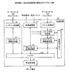
[伝送装置の構成]
次に、本実施例に係る伝送装置の構成について説明する。図7は、実施例2に係る伝送装置の構成を示すブロック図である。なお、伝送装置10は、図7に示した機能部以外にも既知のコンピュータが有する各種の機能部、例えば各種の入力デバイスや表示デバイスなどの機能を有するものとする。
[Configuration of transmission equipment]
Next, the configuration of the transmission apparatus according to the present embodiment will be described. FIG. 7 is a block diagram illustrating the configuration of the transmission apparatus according to the second embodiment. In addition to the functional units illustrated in FIG. 7, the
図7に示す伝送装置10は、パケット受信部11と、パケット送信部12と、再送通信部13と、バッファ14aと、作業用メモリ14bと、再生処理部15とを有する。さらに、伝送装置10は、FECパケット情報付加部16と、パケットロス判定部17と、FECパケット情報変更部18と、FECパケット生成制御部19とを有する。なお、図7に示した再生処理部15は、必ずしもノード#1〜ノード#11の全てのノードに設ける必要はない。また、図7に示したFECパケット情報付加部16は、最上位の階層とされるノード#1だけに設けることもできる。
The
パケット受信部11は、上位階層のノードから送信されるデータパケットまたはFECパケットのいずれかのパケットを受信する処理部である。
The
パケット送信部12は、データパケットまたはFECパケットを下位階層のノードへ送信する処理部である。一例としては、パケット送信部12は、バッファ14aに格納されたデータパケットおよびFECパケットをエンコード時のVBR(Variable Bit Rate)、すなわち可変レートで送信する。なお、ここでは、可変レートで転送する場合を説明したが、CBR(constant bit rate)、すなわち固定レートで転送することもできる。
The
再送通信部13は、上位階層のノードとの間で再送に関する通信を行う処理部である。一例としては、再送通信部13は、後述のパケットロス判定部17による指示に基づき、上位階層のノードへデータパケットの再送要求を行う。他の一例としては、再送通信部13は、上位階層のノードから再送されたデータパケットを受信する。
The
バッファ(buffer)14aは、パケット受信部11または再送通信部13により受信されたパケットを蓄積する記憶デバイスである。このバッファ14aは、ノード間における伝送ジッタ(jitter)を吸収するために用いられる。また、作業用メモリ14bは、後述のパケットロス判定部17、FECパケット情報変更部18及びFECパケット生成制御部19により使用されるメモリである。
The
これらバッファ14a及び作業用メモリ14bの一例としては、RAM(Random Access Memory)、ROM(Read Only Memory)やフラッシュメモリ(flash memory)などの半導体メモリ素子が採用される。なお、バッファ14aは、ハードディスク、光ディスクなどの記憶装置を採用することとしてもかまわない。
As an example of the
再生処理部15は、バッファ14aに格納されたデータパケットの再生処理を行う処理部である。一例として、メディアデータの圧縮符号化方式としてMPEGを用いる場合には、再生処理部は、データパケットをデコード(decode)するMPEGデコーダ(decoder)として機能する。再生処理部15は、デコードしたメディアデータを図示しない表示部及び音声出力部を介して再生する。なお、メディアデータの圧縮符号化方式は、必ずしもMPEGである必要はなく、他の符号化方式を用いることとしてもよい。
The
FECパケット情報付加部16は、メディアデータからパケット化されたデータパケットにFECパケット情報を付加する処理部である。このFECパケット情報には、FECパケットが誤り訂正を実行することにより復元可能なデータパケットの保護範囲、FECパケットに付与されるシーケンス番号、データパケットの受信順に付与される追加シーケンス番号が挙げられる。なお、FECパケット情報の付加は、図2に示すノード#2及びノード#9以降の下位階層のノードでは実行されない。
The FEC packet
図8は、FECパケット情報付加部16により付加されるFECパケット情報の一例を示す図である。なお、図8の例では、FECパケット情報に該当する部分の塗りつぶしを網掛けにより図示している。図8に示すように、FECパケット情報付加部16は、FECパケットによるRTPパケットの保護範囲を保護対象とするRTPパケットの「CSRC」の後に「FEC Coverage」として付加する。また、FECパケット情報付加部16は、FECパケットのシーケンス番号を保護対象とするRTPパケットの「FEC Coverage」の後に「FEC Sequence Number」として付加する。さらに、FECパケット情報付加部16は、追加シーケンス番号を保護対象とするRTPパケットの「FEC Sequence Number」の後に「Additional Sequence Number」として付加する。
FIG. 8 is a diagram illustrating an example of FEC packet information added by the FEC packet
図9は、RTPパケットが含むFECパケット情報の一例を示す図である。図9に示す例では、パケットを模式化した小包にRTPパケットにFECパケット情報を図示している。図9に示す符号31は、メディアデータをパケット化する際にデータパケットに付与されたデータパケットのシーケンス番号を指す。図9に示す符号32は、各伝送装置でデータパケットの受信順に付与される追加シーケンス番号を指す。図9に示す符号33は、FECパケットによるRTPパケットの保護範囲を指す。また、図9に示す符号34は、FECパケットのシーケンス番号を指す。
FIG. 9 is a diagram illustrating an example of FEC packet information included in the RTP packet. In the example illustrated in FIG. 9, the FEC packet information is illustrated in the RTP packet in a packet that schematically represents the packet. The code |
図9に示す例では、RTPパケットのシーケンス番号が「1」であり、RTPパケットの追加シーケンス番号が「1」であることを示し、また、RTPパケットを保護するFECパケットのシーケンス番号が「1」であることを示す。さらに、図9に示す例では、FECパケットが保護対象とするRTPパケット数が「4」であることを示す。すなわち、幾つのRTPパケットから生成されたパリティ情報であるのかを示すことにもなる。 In the example illustrated in FIG. 9, the sequence number of the RTP packet is “1”, the additional sequence number of the RTP packet is “1”, and the sequence number of the FEC packet that protects the RTP packet is “1”. ". Furthermore, the example illustrated in FIG. 9 indicates that the number of RTP packets to be protected by the FEC packet is “4”. That is, it indicates the number of parity information generated from the number of RTP packets.
図7の説明に戻り、パケットロス判定部17は、パケット受信部11により受信されたFECパケット情報を用いて、データパケットのパケットロスを判定する処理部である。
Returning to the description of FIG. 7, the packet loss determination unit 17 is a processing unit that determines the packet loss of the data packet using the FEC packet information received by the
このパケットロス判定部17は、パケット受信部11または再送通信部13によりパケットが受信される度に、作業用メモリ14b内に記憶されたデータパケットの受信回数を加算する更新を行う。すなわち、パケットロス判定部17は、作業用メモリ14bを用いて、最初にパケットを受信してから今回受信するまでのデータパケットの累積受信回数を計測する。これにより受信パケットの受信順序を判別する。
The packet loss determination unit 17 performs an update to add the number of receptions of the data packet stored in the working
まず、パケット受信部11により再送ではない通常のデータパケットを受信した場合のパケットロスの判定要領について説明する。データパケットを受信した場合には、パケットロス判定部17は、最初の受信パケットであるか否かを判定する。このとき、最初の受信パケットであった場合には、パケットロス判定部17は、追加シーケンス番号、FECパケットの保護範囲及びFECパケットのシーケンス番号などのFECパケット情報を作業用メモリ14bへ登録する。そして、パケットロス判定部17は、下位階層への伝送用とは別にFECパケットの生成に使用するためのデータパケットを複製した上でバッファ14aへ格納する。
First, the packet loss determination procedure when a normal data packet that is not retransmitted is received by the
一方、最初の受信パケットではない場合には、パケットロス判定部17は、今回に受信したデータパケットのRTPヘッダに書き込まれている追加シーケンス番号と、1つ前に受信したデータパケットの追加シーケンス番号とが連番であるか否かを判定する。つまり、パケットロス判定部17は、前後に受信したデータパケットの追加シーケンス番号の差が1であるか否かを判定する。このように、追加シーケンス番号が連番であるか否かを判定することにより、パケットロスの有無が検知できる。 On the other hand, if it is not the first received packet, the packet loss determination unit 17 adds the additional sequence number written in the RTP header of the data packet received this time and the additional sequence number of the previous data packet received Whether or not is a serial number is determined. That is, the packet loss determination unit 17 determines whether or not the difference between the additional sequence numbers of the data packets received before and after is 1. Thus, the presence or absence of packet loss can be detected by determining whether or not the additional sequence number is a serial number.
さらに、パケットロス判定部17は、作業用メモリ14bに記憶されたFECパケット情報を参照して、今回に受信したデータパケットと前回に受信したデータパケットのとの間でFECパケットの保護範囲及びシーケンス番号が同一であるか否かを判定する。このように、FECパケットの保護範囲及びシーケンス番号が同一であるか否かを判定することにより、後述のFECパケット情報変更部18により追加シーケンス番号だけを変更するのか、あるいはFECパケット情報も併せて変更するのかを判断できる。
Further, the packet loss determination unit 17 refers to the FEC packet information stored in the working
このとき、追加シーケンス番号が連番であり、かつFECパケットの保護範囲及びシーケンス番号が同一である場合には、パケットロス判定部17は、今回に受信したデータパケットのXORを後述のFECパケット生成制御部19に算出させる。その後、パケットロス判定部17は、作業用メモリ14bに記憶されている追加シーケンス番号を今回に受信したデータパケットの追加シーケンス番号に更新する。そして、パケットロス判定部17は、今回までにXORが算出されたデータパケットの数が作業用メモリ14bに記憶されたFECパケットの保護範囲に到達したか否かを判定する。この結果、FECパケットの保護範囲に到達した場合には、パケットロス判定部17は、それまでに算出されていたXORの算出結果を用いてFECパケットを生成するようにFECパケット生成制御部19に指示する。
At this time, if the additional sequence number is a sequential number and the protection range and sequence number of the FEC packet are the same, the packet loss determination unit 17 generates an XOR of the data packet received this time to generate an FEC packet described later. The
また、追加シーケンス番号が連番であり、かつFECパケットの保護範囲及びシーケンス番号が同一でない場合には、パケットロス判定部17は、次のFECパケットの生成に使用するためのデータパケットを複製した上でバッファ14aへ格納する。その後、パケットロス判定部17は、今回受信したデータパケットの追加シーケンス番号、FECパケットの保護範囲及びFECパケットのシーケンス番号などのFECパケット情報を作業用メモリ14bへ登録する。ここでのFECパケット情報の登録は、今回までに受信したデータパケットを保護していたFECパケットの次のFECパケットにより保護されているデータパケットに関するパケットロスを判定するために実行される。
If the additional sequence number is a sequential number and the FEC packet protection range and the sequence number are not the same, the packet loss determination unit 17 duplicates the data packet to be used for generating the next FEC packet. The data is stored in the
また、追加シーケンス番号が連番ではなく、かつFECパケットの保護範囲及びシーケンス番号が同一である場合には、パケットロス判定部17は、次のような処理を行う。すなわち、パケットロス判定部17は、今回に受信したデータパケットに書き込まれているFECパケットの保護範囲において再送を要するパケット数がロスしているか否かを判定する。一例として、FECパケットにより復元可能なパケット数が1つである場合には、パケットロス判定部17は、パケットロス数が2つ以上であるか否かを判定する。このとき、再送を要するパケット数をロスしている場合には、パケットロス判定部17は、パケットロスしているデータパケットのうち追加シーケンス番号が小さいものから順に所定数のデータパケットの再送要求を再送通信部13に送信させる。一例として、パケットロス数が2つである場合には、パケットロス判定部17は、FECパケットにより復元可能なパケット数「1」を残し、他のデータパケットの再送要求を再送通信部13に送信させる。その上で、パケットロス判定部17は、再送要求を行ったデータパケットに関する情報、例えばデータパケットのシーケンス番号を作業用メモリ14b内に記憶された再送待ちリストへ登録する。その後、パケットロス判定部17は、作業用メモリ14bに記憶されている追加シーケンス番号を今回に受信したデータパケットの追加シーケンス番号に更新する。
When the additional sequence number is not a sequential number and the protection range and sequence number of the FEC packet are the same, the packet loss determination unit 17 performs the following process. That is, the packet loss determination unit 17 determines whether or not the number of packets that need to be retransmitted is lost in the protection range of the FEC packet written in the data packet received this time. As an example, when the number of packets that can be restored by the FEC packet is one, the packet loss determination unit 17 determines whether or not the number of packet losses is two or more. At this time, when the number of packets that need to be retransmitted is lost, the packet loss determination unit 17 requests retransmission of a predetermined number of data packets in order from the smallest additional sequence number among the data packets that are lost. The
また、追加シーケンス番号が連番ではなく、かつFECパケットの保護範囲及びシーケンス番号が同一ではない場合には、パケットロス判定部17は、次のような処理を行う。すなわち、パケットロス判定部17は、今回に受信したデータパケットに書き込まれているFECパケットの保護範囲の直前の保護範囲、すなわち作業用メモリ14bに記憶されている保護範囲において再送を要するパケット数をロスしているか否かを判定する。このとき、再送を要するパケット数をロスしている場合には、パケットロス判定部17は、パケットロスしているデータパケットのうち追加シーケンス番号が小さいものから順に所定数のデータパケットの再送要求を再送通信部13に送信させる。その上で、パケットロス判定部17は、再送要求を行ったデータパケットに関する情報、例えばデータパケットのシーケンス番号を作業用メモリ14b内に記憶された再送待ちリストへ登録する。その後、パケットロス判定部17は、作業用メモリ14bに記録されているFECパケット情報を今回に受信したデータパケットの追加シーケンス番号、FECパケットの保護範囲及びFECパケットのシーケンス番号へ更新する。
When the additional sequence number is not a sequential number and the protection range and sequence number of the FEC packet are not the same, the packet loss determination unit 17 performs the following process. That is, the packet loss determination unit 17 determines the number of packets that need retransmission in the protection range immediately before the protection range of the FEC packet written in the data packet received this time, that is, the protection range stored in the working
次に、パケット受信部11によりFECパケットを受信した場合のパケットロスの判定要領について説明する。FECパケットを受信した場合には、パケットロス判定部17は、今回に受信したFECパケットにより保護されているデータパケットのシーケンス番号を取得する。ここで、パケットロス判定部17は、作業用メモリ14bに記憶された変更情報リストの中に、先に取得したデータパケットのシーケンス番号が登録されているか否かを判定する。なお、変更情報リストは、後述のFECパケット情報変更部18によりFECパケット情報が変更されたデータパケットのシーケンス番号が登録される。
Next, a description will be given of how to determine a packet loss when an FEC packet is received by the
このとき、変更情報リストの中にデータパケットのシーケンス番号が登録されていない場合には、パケットロス判定部17は、データパケットのシーケンス番号に対応するデータパケットをバッファ14aから検索する。一方、変更情報リストの中にデータパケットのシーケンス番号が登録されている場合には、パケットロス判定部17は、変更情報リストに登録されているデータパケットのシーケンス番号に対応するデータパケットをバッファ14aから検索する。この場合には、FECパケット情報が変更される前のデータパケットおよびFECパケット情報が変更された後の両方のデータパケットが抽出されることになる。
At this time, when the sequence number of the data packet is not registered in the change information list, the packet loss determination unit 17 searches the
そして、パケットロス判定部17は、今回に検索したデータパケットに書き込まれているFECパケットの保護範囲において再送を要するパケット数がロスしているか否かを判定する。このとき、再送を要するパケット数をロスしている場合には、パケットロス判定部17は、パケットロスしているデータパケットのうち追加シーケンス番号が小さいものから順に所定数のデータパケットの再送要求を再送通信部13に送信させる。その上で、パケットロス判定部17は、再送要求を行ったデータパケットに関する情報、例えばデータパケットのシーケンス番号を作業用メモリ14b内に記憶された再送待ちリストへ登録する。
Then, the packet loss determination unit 17 determines whether or not the number of packets that require retransmission is lost in the protection range of the FEC packet written in the data packet searched this time. At this time, when the number of packets that need to be retransmitted is lost, the packet loss determination unit 17 requests retransmission of a predetermined number of data packets in order from the smallest additional sequence number among the data packets that are lost. The
一方、再送を要するパケット数をロスしていない場合には、パケットロス判定部17は、今回に検索したデータパケットに書き込まれているFECパケットの保護範囲においてパケットロスが存在するか否かをさらに判定する。このとき、パケットロスが存在する場合には、FECパケットによる復元が可能である。このため、パケットロス判定部17は、今回に受信したFECパケットを用いて、パケットロスしているデータパケットを後述のFECパケット生成制御部19に復元させる。その後、パケットロス判定部17は、作業用メモリ14bに記録されているFECパケット情報を今回に復元したデータパケットの追加シーケンス番号、FECパケットの保護範囲及びFECパケットのシーケンス番号へ更新する。
On the other hand, if the number of packets that need to be retransmitted is not lost, the packet loss determination unit 17 further determines whether or not there is a packet loss in the protection range of the FEC packet written in the data packet searched this time. judge. At this time, if there is a packet loss, restoration by the FEC packet is possible. For this reason, the packet loss determination unit 17 causes the FEC packet generation control unit 19 (to be described later) to restore the data packet that has lost the packet using the FEC packet received this time. Thereafter, the packet loss determination unit 17 updates the FEC packet information recorded in the working
FECパケット情報変更部18は、パケット受信部11および再送通信部13によりデータパケットが受信された順番にしたがってデータパケットのFECパケット情報を更新する処理部である。
The FEC packet
一例としては、パケット受信部11によりデータパケットを受信した場合には、FECパケット情報変更部18は、パケットロス判定部17によりパケットロスが検知された場合に、FECパケット情報の変更を行う。このとき、前後のデータパケットにそれぞれ書き込まれているFECパケットの保護範囲及びシーケンス番号が同一であるか否かにより、FECパケット情報のうちいずれの項目の情報を変更するかが変わる。
As an example, when a data packet is received by the
このとき、FECパケットの保護範囲及びシーケンス番号が同一である場合には、FECパケット情報変更部18は、受信したデータパケットのRTPヘッダに書き込まれているFECパケット情報のうち追加シーケンス番号を変更する。つまり、FECパケット情報変更部18は、作業用メモリ14bに記憶された受信回数、すなわちデータパケットの受信順序を今回に受信したデータパケットのRTPヘッダに割り当てられた追加シーケンス番号の領域に書き込む。その上で、FECパケット情報変更部18は、今回に受信したデータパケットに付与されているシーケンス番号を作業用メモリ14b内の変更情報リストへ登録する。
At this time, when the protection range and the sequence number of the FEC packet are the same, the FEC packet
一方、FECパケットの保護範囲及びシーケンス番号が同一でない場合には、FECパケット情報変更部18は、次のような処理を行う。すなわち、FECパケット情報変更部18は、受信したデータパケットのRTPヘッダに書き込まれている追加シーケンス番号、FECパケットの保護範囲及びFECパケットのシーケンス番号を変更する。その上で、FECパケット情報変更部18は、今回に受信したデータパケットに付与されているシーケンス番号を作業用メモリ14b内の変更情報リストへ登録する。
On the other hand, when the protection range and sequence number of the FEC packet are not the same, the FEC packet
このように、全てのFECパケット情報を変更する場合には、FECパケット情報変更部18は、今回に受信したデータパケットの受信順序をRTPヘッダに割り当てられた追加シーケンス番号の領域に書き込む。さらに、FECパケット情報変更部18は、作業用メモリ14bに記憶されているFECパケットの保護範囲及びFECパケットのシーケンス番号をデータパケットのRTPヘッダに書き込む。
As described above, when all the FEC packet information is changed, the FEC packet
他の一例としては、FECパケット情報変更部18は、後述のFECパケット生成制御部19によりデータパケットが復元された場合にも、復元したデータパケットの全てのFECパケット情報を変更する。その上で、FECパケット情報変更部18は、今回に受信したデータパケットに付与されているシーケンス番号を作業用メモリ14b内の変更情報リストへ登録する。
As another example, the FEC packet
更なる一例としては、FECパケット情報変更部18は、再送通信部13により再送のデータパケットが受信された場合にも、再送パケットの全てのFECパケット情報を変更する。その上で、FECパケット情報変更部18は、今回に受信したデータパケットに付与されているシーケンス番号を作業用メモリ14b内の変更情報リストへ登録する。
As a further example, the FEC packet
FECパケット生成制御部19は、FECパケットの生成を制御する処理部である。一例としては、FECパケット生成制御部19は、パケットロス判定部17による指示に基づき、パケット受信部11により受信されたデータパケット、再送通信部13により受信された再送のデータパケットのXORを算出する。このとき、FECパケット生成制御部19は、XORの算出を終えたデータパケットの数が作業用メモリ14bに記憶されたFECパケットの保護範囲に到達した場合には、それまでに算出したデータパケットのXORからFECパケットを生成する。他の一例としては、FECパケット生成制御部19は、パケット受信部11により受信されたFECパケットを用いて、FECパケットの保護範囲の中でパケットロスしているデータパケットを復元する。
The FEC packet
なお、パケット受信部11、パケット送信部12、再送通信部13、再生処理部15、FECパケット情報付加部16、パケットロス判定部17、FECパケット情報変更部18及びFECパケット生成制御部19には、各種の集積回路や電子回路を採用できる。例えば、集積回路としては、ASIC(Application Specific Integrated Circuit)が挙げられる。また、電子回路としては、CPU(Central Processing Unit)やMPU(Micro Processing Unit)などが挙げられる。
The
[処理の流れ]
次に、本実施例に係る伝送装置の処理の流れについて説明する。図10〜図12は、実施例2に係るパケット受信処理の手順を示すフローチャートである。この処理は、パケット受信部11または再送通信部13のいずれかでパケットが受信された場合に起動する処理である。
[Process flow]
Next, a processing flow of the transmission apparatus according to the present embodiment will be described. 10 to 12 are flowcharts illustrating a procedure of packet reception processing according to the second embodiment. This process is started when a packet is received by either the
図10に示すように、上位階層のノードからパケットを受信すると、パケットロス判定部17は、受信パケットが再送ではない通常のデータパケットであるのか否かを判定する(ステップS101)。 As shown in FIG. 10, when a packet is received from an upper layer node, the packet loss determination unit 17 determines whether the received packet is a normal data packet that is not a retransmission (step S101).
このとき、受信パケットが通常のデータパケットである場合(ステップS101肯定)には、図10に示すステップS103〜S133までのデータパケット受信処理が実行される。また、受信パケットが通常のデータパケットではなくFECパケットである場合(ステップS101否定かつステップS102肯定)には、図11に示すステップS201〜S217のFECパケット受信処理が実行される。また、受信パケットが通常データパケットまたはFECパケットでもなく、再送パケットである場合には、(ステップS101否定かつステップS102否定)には、図12に示すステップS301〜S310の再送パケット受信処理が実行される。 At this time, if the received packet is a normal data packet (Yes at step S101), the data packet receiving process from steps S103 to S133 shown in FIG. 10 is executed. When the received packet is not a normal data packet but an FEC packet (No in step S101 and positive in step S102), the FEC packet reception process in steps S201 to S217 shown in FIG. 11 is executed. If the received packet is not a normal data packet or FEC packet but a retransmission packet (No in step S101 and no in step S102), the retransmission packet reception process in steps S301 to S310 shown in FIG. 12 is executed. The
まず、データパケット受信処理を説明する。受信パケットが通常のデータパケットである場合(ステップS101肯定)には、パケットロス判定部17は、データパケットのRTPヘッダに書き込まれているFECパケット情報を取得する(ステップS103)。例えば、パケットロス判定部17は、FECパケット情報として、追加シーケンス番号、FECパケットの保護範囲およびFECパケットのシーケンス番号を取得する。 First, data packet reception processing will be described. When the received packet is a normal data packet (Yes at Step S101), the packet loss determination unit 17 acquires the FEC packet information written in the RTP header of the data packet (Step S103). For example, the packet loss determination unit 17 acquires the additional sequence number, the FEC packet protection range, and the FEC packet sequence number as the FEC packet information.
続いて、パケットロス判定部17は、データパケットが最初の受信パケットであるか否かを判定する(ステップS104)。このとき、最初の受信パケットであった場合(ステップS104肯定)には、パケットロス判定部17は、次のような処理を実行する。すなわち、パケットロス判定部17は、追加シーケンス番号、FECパケットの保護範囲及びFECパケットのシーケンス番号などのFECパケット情報を作業用メモリ14bへ登録する(ステップS105)。
Subsequently, the packet loss determination unit 17 determines whether or not the data packet is the first received packet (step S104). At this time, when it is the first received packet (Yes at Step S104), the packet loss determination unit 17 executes the following process. That is, the packet loss determination unit 17 registers the FEC packet information such as the additional sequence number, the FEC packet protection range, and the FEC packet sequence number in the
そして、パケットロス判定部17は、下位階層への伝送用とは別にFECパケットの生成に使用するためのデータパケットを複製した上でバッファ14aへ格納する(ステップS106)。続いて、FECパケット生成制御部19は、今回に受信したデータパケットのXORを算出する(ステップS107)。その上で、FECパケット生成制御部19は、今回に受信したデータパケットを伝送用のデータパケットとしてバッファ14aへ格納し(ステップS108)、処理を終了する。
Then, the packet loss determination unit 17 duplicates the data packet for use in generating the FEC packet separately from the transmission to the lower layer, and stores it in the
一方、最初の受信パケットではない場合(ステップS104否定)には、パケットロス判定部17は、次のような処理を実行する。すなわち、パケットロス判定部17は、今回に受信したデータパケットのRTPヘッダに書き込まれている追加シーケンス番号と、1つ前に受信したデータパケットの追加シーケンス番号とが連番であるか否かを判定する(ステップS109)。 On the other hand, when it is not the first received packet (No at Step S104), the packet loss determination unit 17 executes the following process. That is, the packet loss determination unit 17 determines whether or not the additional sequence number written in the RTP header of the data packet received this time and the additional sequence number of the previous data packet received are serial numbers. Determination is made (step S109).
さらに、パケットロス判定部17は、今回に受信したデータパケットと前回に受信したデータパケットのとの間でFECパケットの保護範囲及びシーケンス番号が同一であるか否かを判定する(ステップS110およびステップS117)。 Further, the packet loss determination unit 17 determines whether or not the protection range and sequence number of the FEC packet are the same between the data packet received this time and the data packet received last time (step S110 and step S110). S117).
ここで、追加シーケンス番号が連番であり、かつFECパケットの保護範囲及びシーケンス番号が同一である場合(ステップS110肯定かつステップS117肯定)には、FECパケット生成制御部19は、次のような処理を実行する。すなわち、FECパケット生成制御部19は、今回に受信したデータパケットのXORを算出する(ステップS111)。
Here, when the additional sequence number is a serial number and the protection range and sequence number of the FEC packet are the same (Yes at Step S110 and Yes at Step S117), the FEC packet
そして、FECパケット生成制御部19は、XORの算出を終えたデータパケットの数が作業用メモリ14bに記憶されたFECパケットの保護範囲に到達したか否かを判定する(ステップS112)。続いて、FECパケットの保護範囲に到達した場合(ステップS112肯定)には、FECパケット生成制御部19は、それまでに算出したデータパケットのXORからFECパケットを生成する(ステップS113)。
Then, the FEC packet
その後、パケットロス判定部17は、作業用メモリ14bに記憶されている追加シーケンス番号を今回に受信したデータパケットの追加シーケンス番号に更新する(ステップS114)。そして、FECパケット生成制御部19は、パケット受信部11により受信されたデータパケットとともに今回生成したFECパケットをバッファ14aへ格納し(ステップS108)、処理を終了する。
Thereafter, the packet loss determination unit 17 updates the additional sequence number stored in the working
また、追加シーケンス番号が連番であり、かつFECパケットの保護範囲及びシーケンス番号が同一でない場合(ステップS109肯定かつステップS110否定)には、パケットロス判定部17は、次のような処理を実行する。すなわち、パケットロス判定部17は、次のFECパケットの生成に使用するためのデータパケットを複製した上でバッファ14aへ格納する(ステップS115)。
If the additional sequence number is a sequential number and the FEC packet protection range and the sequence number are not the same (Yes at Step S109 and No at Step S110), the packet loss determination unit 17 performs the following processing: To do. That is, the packet loss determination unit 17 duplicates the data packet to be used for generating the next FEC packet and stores it in the
そして、パケットロス判定部17は、今回受信したデータパケットの追加シーケンス番号、FECパケットの保護範囲及びFECパケットのシーケンス番号などのFECパケット情報を作業用メモリ14bへ更新する(ステップS116)。その後、FECパケット生成制御部19は、今回に受信したデータパケットを伝送用のデータパケットとしてバッファ14aへ格納し(ステップS108)、処理を終了する。
Then, the packet loss determination unit 17 updates the FEC packet information such as the additional sequence number of the data packet received this time, the protection range of the FEC packet, and the sequence number of the FEC packet to the working
また、追加シーケンス番号が連番ではなく、かつFECパケットの保護範囲及びシーケンス番号が同一である場合(ステップS109否定かつステップS117肯定)には、パケットロス判定部17は、次のような処理を行う。すなわち、パケットロス判定部17は、今回に受信したデータパケットに書き込まれているFECパケットの保護範囲において所定数、例えば再送を要するパケット数がロスしているか否かを判定する(ステップS118)。なお、再送を要するパケット数をロスしていない場合(ステップS118否定)には、そのままステップS121の処理へ移行する。 When the additional sequence number is not a sequential number and the FEC packet protection range and sequence number are the same (No at step S109 and positive at step S117), the packet loss determination unit 17 performs the following processing. Do. That is, the packet loss determination unit 17 determines whether or not a predetermined number, for example, the number of packets that require retransmission is lost in the protection range of the FEC packet written in the data packet received this time (step S118). If the number of packets that need to be retransmitted has not been lost (No at Step S118), the process directly proceeds to Step S121.
このとき、再送を要するパケット数をロスしている場合(ステップS118肯定)には、パケットロス判定部17は、次のような処理を行う。すなわち、パケットロス判定部17は、パケットロスしているデータパケットのうち追加シーケンス番号が小さいものから順に不足分のデータパケットの再送要求を再送通信部13に送信させる(ステップS119)。その上で、パケットロス判定部17は、再送要求を行ったデータパケットに関する情報、例えばデータパケットのシーケンス番号を作業用メモリ14b内に記憶された再送待ちリストへ登録する(ステップS120)。
At this time, if the number of packets that need to be retransmitted is lost (Yes at step S118), the packet loss determination unit 17 performs the following processing. In other words, the packet loss determination unit 17 causes the
そして、FECパケット情報変更部18は、受信したデータパケットのRTPヘッダに書き込まれているFECパケット情報のうち追加シーケンス番号を変更する(ステップS121)。その上で、FECパケット情報変更部18は、今回に受信したデータパケットに付与されているシーケンス番号を作業用メモリ14b内の変更情報リストへ登録する(ステップS122)。
Then, the FEC packet
続いて、パケットロス判定部17は、作業用メモリ14bに記憶されている追加シーケンス番号を今回に受信したデータパケットの追加シーケンス番号に更新する(ステップS123)。そして、FECパケット生成制御部19は、今回に受信したデータパケットのXORを算出する(ステップS124)。その後、FECパケット生成制御部19は、パケット受信部11により受信されたデータパケットをバッファ14aへ格納し(ステップS108)、処理を終了する。
Subsequently, the packet loss determination unit 17 updates the additional sequence number stored in the
また、追加シーケンス番号が連番ではなく、かつFECパケットの保護範囲及びシーケンス番号が同一ではない場合(ステップS109否定かつステップS117否定)には、パケットロス判定部17は、次のような処理を行う。すなわち、パケットロス判定部17は、今回に受信したデータパケットに書き込まれているFECパケットの保護範囲の直前の保護範囲において所定数、例えば再送を要するパケット数をロスしているか否かを判定する(ステップS125)。なお、再送を要するパケット数をロスしていない場合(ステップS125否定)には、そのままステップS128の処理へ移行する。 If the additional sequence number is not a sequential number and the protection range and sequence number of the FEC packet are not the same (No at step S109 and negative at step S117), the packet loss determination unit 17 performs the following processing. Do. That is, the packet loss determination unit 17 determines whether or not a predetermined number, for example, the number of packets that need to be retransmitted is lost in the protection range immediately before the protection range of the FEC packet written in the currently received data packet. (Step S125). If the number of packets that need to be retransmitted has not been lost (No at Step S125), the process directly proceeds to Step S128.
このとき、再送を要するパケット数をロスしている場合(ステップS125肯定)には、パケットロス判定部17は、次のような処理を行う。すなわち、パケットロス判定部17は、パケットロスしているデータパケットのうち追加シーケンス番号が小さいものから順に不足分のデータパケットの再送要求を再送通信部13に送信させる(ステップS126)。その上で、パケットロス判定部17は、再送要求を行ったデータパケットに関する情報、例えばデータパケットのシーケンス番号を作業用メモリ14b内に記憶された再送待ちリストへ登録する(ステップS127)。
At this time, if the number of packets that need to be retransmitted is lost (Yes at step S125), the packet loss determination unit 17 performs the following processing. In other words, the packet loss determination unit 17 causes the
そして、FECパケット情報変更部18は、受信したデータパケットのRTPヘッダに書き込まれている追加シーケンス番号、FECパケットの保護範囲及びFECパケットのシーケンス番号を変更する(ステップS128)。その上で、FECパケット情報変更部18は、今回に受信したデータパケットに付与されているシーケンス番号を作業用メモリ14b内の変更情報リストへ登録する(ステップS129)。
Then, the FEC packet
その後、パケットロス判定部17は、作業用メモリ14bに記録されているFECパケット情報を今回に受信したデータパケットの追加シーケンス番号、FECパケットの保護範囲及びFECパケットのシーケンス番号へ更新する(ステップS130)。
Thereafter, the packet loss determination unit 17 updates the FEC packet information recorded in the working
続いて、FECパケット生成制御部19は、今回に受信したデータパケットのXORを算出する(ステップS131)。そして、FECパケット生成制御部19は、XORの算出を終えたデータパケットの数が作業用メモリ14bに記憶されたFECパケットの保護範囲に到達したか否かを判定する(ステップS132)。
Subsequently, the FEC packet
そして、FECパケットの保護範囲に到達した場合(ステップS132肯定)には、それまでに算出したデータパケットのXORからFECパケットを生成する(ステップS133)。その後、FECパケット生成制御部19は、パケット受信部11により受信されたデータパケットとともに今回生成したFECパケットをバッファ14aへ格納し(ステップS108)、処理を終了する。
When the protection range of the FEC packet is reached (Yes at step S132), an FEC packet is generated from the XOR of the data packet calculated so far (step S133). Thereafter, the FEC packet
また、FECパケットの保護範囲に到達していない場合(ステップS132否定)には、FECパケット生成制御部19は、パケット受信部11により受信されたデータパケットをバッファ14aへ格納し(ステップS108)、処理を終了する。
If the FEC packet protection range has not been reached (No at Step S132), the FEC packet
次に、図11を用いて、上述したFECパケット受信処理について説明する。FECパケットを受信した場合(ステップS102肯定)には、パケットロス判定部17は、今回に受信したFECパケットにより保護されているデータパケットのシーケンス番号を取得する(ステップS201)。 Next, the FEC packet reception process described above will be described with reference to FIG. When the FEC packet is received (Yes at Step S102), the packet loss determination unit 17 acquires the sequence number of the data packet protected by the FEC packet received this time (Step S201).
ここで、パケットロス判定部17は、作業用メモリ14bに記憶された変更情報リストの中に、先に取得したデータパケットのシーケンス番号が登録されているか否かを判定する(ステップS202)。
Here, the packet loss determination unit 17 determines whether or not the sequence number of the previously acquired data packet is registered in the change information list stored in the
このとき、変更情報リストの中にデータパケットのシーケンス番号が登録されている場合(ステップS202肯定)には、パケットロス判定部17は、次のような処理を実行する。すなわち、パケットロス判定部17は、FECパケット情報が変更される前のデータパケットおよびFECパケット情報が変更された後の両方のデータパケットをバッファ14aから検索する(ステップS203)。
At this time, when the sequence number of the data packet is registered in the change information list (Yes at Step S202), the packet loss determination unit 17 executes the following process. That is, the packet loss determination unit 17 searches the
一方、変更情報リストの中にデータパケットのシーケンス番号が登録されていない場合(ステップS202否定)には、パケットロス判定部17は、データパケットのシーケンス番号に対応するデータパケットをバッファ14aから検索する(ステップS204)。
On the other hand, when the sequence number of the data packet is not registered in the change information list (No at Step S202), the packet loss determination unit 17 searches the
そして、パケットロス判定部17は、今回に検索したデータパケットに書き込まれているFECパケットの保護範囲において再送を要するパケット数がロスしているか否かを判定する(ステップS205)。 Then, the packet loss determination unit 17 determines whether or not the number of packets that require retransmission is lost in the protection range of the FEC packet written in the data packet searched this time (step S205).
このとき、再送を要するパケット数をロスしている場合(ステップS205肯定)には、パケットロス判定部17は、次のような処理を行う。すなわち、パケットロス判定部17は、パケットロスしたデータパケット、すなわち再送要求の対象とするパケットが作業用メモリ14bに記憶された再送待ちリストに登録されているか否かを判定する(ステップS206)。なお、再送待ちリストに登録されていない場合(ステップS206否定)には、そのまま処理を終了する。
At this time, if the number of packets that need to be retransmitted is lost (Yes at Step S205), the packet loss determination unit 17 performs the following processing. That is, the packet loss determination unit 17 determines whether or not the data packet that has been lost, that is, the packet that is the target of the retransmission request, is registered in the retransmission wait list stored in the working
そして、再送待ちリストに登録されている場合(ステップS206肯定)には、パケットロス判定部17は、次のような処理を実行する。すなわち、パケットロス判定部17は、パケットロスしているデータパケットのうち追加シーケンス番号が小さいものから順に不足分のデータパケットの再送要求を再送通信部13に送信させる(ステップS207)。その上で、パケットロス判定部17は、再送要求を行ったデータパケットに関する情報、例えばデータパケットのシーケンス番号を作業用メモリ14b内に記憶された再送待ちリストへ登録し(ステップS208)、処理を終了する。
When registered in the retransmission wait list (Yes at Step S206), the packet loss determination unit 17 executes the following process. In other words, the packet loss determination unit 17 causes the
一方、再送を要するパケット数をロスしていない場合(ステップS205否定)には、パケットロス判定部17は、次のような処理を行う。すなわち、パケットロス判定部17は、今回に検索したデータパケットに書き込まれているFECパケットの保護範囲においてパケットロスが存在するか否かをさらに判定する(ステップS209)。 On the other hand, when the number of packets that need to be retransmitted has not been lost (No at Step S205), the packet loss determination unit 17 performs the following processing. That is, the packet loss determination unit 17 further determines whether or not there is a packet loss in the protection range of the FEC packet written in the data packet searched this time (step S209).
このとき、パケットロスが存在しない場合(ステップS209否定)には、そのまま処理を終了する。一方、パケットロスが存在する場合(ステップS209肯定)には、FECパケット生成制御部19は、今回に受信したFECパケットを用いて、パケットロスしているデータパケットを復元する(ステップS210)。
At this time, if there is no packet loss (No at Step S209), the processing is terminated as it is. On the other hand, when there is a packet loss (Yes at Step S209), the FEC packet
そして、FECパケット情報変更部18は、復元したデータパケットのRTPヘッダに書き込まれている追加シーケンス番号、FECパケットの保護範囲及びFECパケットのシーケンス番号を変更する(ステップS211)。その上で、FECパケット情報変更部18は、復元したデータパケットに付与されているシーケンス番号を作業用メモリ14b内の変更情報リストへ登録する(ステップS212)。
Then, the FEC packet
その後、パケットロス判定部17は、作業用メモリ14bに記録されているFECパケット情報を今回に復元したデータパケットの追加シーケンス番号、FECパケットの保護範囲及びFECパケットのシーケンス番号へ更新する(ステップS213)。
Thereafter, the packet loss determination unit 17 updates the FEC packet information recorded in the working
続いて、FECパケット生成制御部19は、復元したデータパケットのXORを算出する(ステップS214)。そして、FECパケット生成制御部19は、XORの算出を終えたデータパケットの数が作業用メモリ14bに記憶されたFECパケットの保護範囲に到達したか否かを判定する(ステップS215)。
Subsequently, the FEC packet
そして、FECパケットの保護範囲に到達した場合(ステップS215肯定)には、それまでに算出したデータパケットのXORからFECパケットを生成する(ステップS216)。その後、FECパケット生成制御部19は、今回に復元したデータパケットとともに今回に生成したFECパケットをバッファ14aへ格納し(ステップS217)、処理を終了する。
When the protection range of the FEC packet is reached (Yes at step S215), an FEC packet is generated from the XOR of the data packet calculated so far (step S216). Thereafter, the FEC packet
また、FECパケットの保護範囲に到達していない場合(ステップS215否定)には、FECパケット生成制御部19は、今回に復元したデータパケットをバッファ14aへ格納し(ステップS217)、処理を終了する。
If the FEC packet protection range has not been reached (No at Step S215), the FEC packet
次に、図12を用いて、上述した再送パケット受信処理について説明する。再送のデータパケットを受信した場合(ステップS102否定)には、パケットロス判定部17は、再送のデータパケットのRTPヘッダに書き込まれているデータパケットのシーケンス番号を取得する(ステップS301)。 Next, the above-described retransmission packet reception process will be described with reference to FIG. When the retransmission data packet is received (No at Step S102), the packet loss determination unit 17 acquires the sequence number of the data packet written in the RTP header of the retransmission data packet (Step S301).
そして、パケットロス判定部17は、再送のデータパケットのシーケンス番号が作業用メモリ14bに記憶された再送待ちリストに登録されているか否かを判定する(ステップS302)。なお、再送待ちリストに登録されていない場合(ステップS302否定)には、そのまま処理を終了する。
Then, the packet loss determination unit 17 determines whether or not the sequence number of the retransmission data packet is registered in the retransmission wait list stored in the
そして、再送待ちリストに登録されている場合(ステップS302肯定)には、パケットロス判定部17は、再送を受けたデータパケットのシーケンス番号を再送待ちリストから削除する(ステップS303)。 If it is registered in the retransmission wait list (Yes at Step S302), the packet loss determination unit 17 deletes the sequence number of the data packet that has been retransmitted from the retransmission wait list (Step S303).
そして、FECパケット情報変更部18は、再送されたデータパケットのRTPヘッダに書き込まれている追加シーケンス番号、FECパケットの保護範囲及びFECパケットのシーケンス番号を変更する(ステップS304)。その上で、FECパケット情報変更部18は、再送されたデータパケットに付与されているシーケンス番号を作業用メモリ14b内の変更情報リストへ登録する(ステップS305)。
Then, the FEC packet
その後、パケットロス判定部17は、作業用メモリ14bに記録されているFECパケット情報を今回に再送されたデータパケットの追加シーケンス番号、FECパケットの保護範囲及びFECパケットのシーケンス番号へ更新する(ステップS306)。
Thereafter, the packet loss determination unit 17 updates the FEC packet information recorded in the working
続いて、FECパケット生成制御部19は、再送されたデータパケットのXORを算出する(ステップS307)。そして、FECパケット生成制御部19は、XORの算出を終えたデータパケットの数が作業用メモリ14bに記憶されたFECパケットの保護範囲に到達したか否かを判定する(ステップS308)。
Subsequently, the FEC packet
そして、FECパケットの保護範囲に到達した場合(ステップS308肯定)には、それまでに算出したデータパケットのXORからFECパケットを生成する(ステップS309)。その後、FECパケット生成制御部19は、今回に再送されたデータパケットとともに今回に生成したFECパケットをバッファ14aへ格納し(ステップS310)、処理を終了する。
If the protection range of the FEC packet is reached (Yes at step S308), an FEC packet is generated from the XOR of the data packet calculated so far (step S309). Thereafter, the FEC packet
また、FECパケットの保護範囲に到達していない場合(ステップS308否定)には、FECパケット生成制御部19は、今回に再送されたデータパケットをバッファ14aへ格納し(ステップS310)、処理を終了する。
If the FEC packet protection range is not reached (No at Step S308), the FEC packet
[実施例2の効果]
上述してきたように、本実施例に係る伝送装置10は、FECパケットをロスしたとしてもそのFECパケットにより保護されるデータパケットの再送が発生しない限りは、データパケットの受信を終えた段階でFECパケットが再生成される。それゆえ、本実施例に係る伝送装置10では、FECパケットがロスしたままの状態で下位階層のノードへデータ伝送が継続される可能性を低減でき、FECパケットのロスに起因する伝送遅延の増大を抑制できる。また、本実施例に係る伝送装置10では、同一のFECパケットに保護されていたデータパケットのうち一部のパケットの伝送順序が再送により乖離しても、FECパケットの保護範囲を下位階層のノードへの伝送順序が近いもの同士に再編成できる。このため、異なるノード間で再送が繰り返し発生した場合に、伝送遅延が拡大する可能性を低減できる。よって、本実施例に係る伝送装置10によれば、データパケットを可変レートで伝送する場合に発生する伝送遅延を抑制することが可能である。
[Effect of Example 2]
As described above, the
さらに、本実施例に係る伝送装置10は、データパケットが受信された場合に、該データパケットに含まれる追加シーケンス番号を用いて、データパケットのパケットロスを判定する。そして、本実施例に係る伝送装置10は、パケットロスの判定結果に基づき、上位階層のノードへデータパケットの再送要求を行い、再送されたデータパケットを受信する。その上で、本実施例に係る伝送装置10は、再送により受信したデータパケットを含め、データパケットを受信した順番にしたがってデータパケットのFECパケット情報を更新する。このため、本実施例に係る伝送装置10では、データパケットを受信する度にパケットロスの有無を検知することができる。それゆえ、本実施例に係る伝送装置10によれば、データパケットの待機時間を低減しつつ、データパケットを可変レートで伝送する場合に発生する伝送遅延を抑制することが可能である。
Furthermore, when a data packet is received, the
かかる効果を伝送例を挙げて説明する。図13は、実施例2に係る伝送装置によるデータ伝送の一例を示す図である。図13に示す例では、ノード#1からノード#2へデータが転送される場合を想定する。また、図13に示す例では、パケットを模式化した小包にデータパケットに付与されたシーケンス番号、追加シーケンス番号、FECパケットの保護範囲およびFECパケットに付与されたシーケンス番号を図示している。図13に示すFECパケット1は、誤り訂正によりデータパケット1〜4を保護するものとし、図13に示すFECパケット2は、誤り訂正によりデータパケット5〜7を保護するものとする。なお、図13に示す例では、FECパケットにより復元可能なパケット数を1つとする。
Such an effect will be described with a transmission example. FIG. 13 is a diagram illustrating an example of data transmission by the transmission apparatus according to the second embodiment. In the example shown in FIG. 13, it is assumed that data is transferred from
図13に示すように、各データパケットには、ノード#1のFECパケット情報付加部16によりデータパケットの送信順に追加シーケンス番号が1つずつインクリメントされて付加される。さらに、各データパケットには、ノード#1のFECパケット情報付加部16によりFECパケットの保護範囲が付加される。一例としては、FECパケット1は、データパケット1〜4から生成されているので、FECパケット1が保護するパケット数「4」がデータパケット1〜4のFECパケットの保護範囲として付加される。さらに、各データパケットには、ノード#1のFECパケット情報付加部16によりFECパケットに付与されるシーケンス番号も付加される。なお、ノード#2以降のノードでは、FECパケット情報が既に付加されているので、FECパケット情報付加部16によるFECパケット情報の付加は実行されない。
As shown in FIG. 13, an additional sequence number is incremented and added to each data packet by the FEC packet
このようにFECパケット情報を付加する場合には、データパケットごとに図10に示した「FEC Coverage」のフィールドにFECパケットの保護範囲(4,3,・・・)が付加されることになる。また、図8に示したFECパケットのRTPヘッダの「SN Base」及び「Mask」は、追加シーケンス番号を基に設定されるものとする。一例としては、FECパケット1の場合は、「SN Base:1、Mask:0xF00000」と設定する。この場合には、上位4bitが保護対象となる。ここでは、追加シーケンス番号を基に設定しているが、データパケットのシーケンス番号を用いて、「SN Base」及び「Mask」を設定することとしてもよい。
When the FEC packet information is added in this way, the protection range (4, 3,...) Of the FEC packet is added to the “FEC Coverage” field shown in FIG. 10 for each data packet. . Further, it is assumed that “SN Base” and “Mask” of the RTP header of the FEC packet shown in FIG. 8 are set based on the additional sequence number. As an example, in the case of the
図13に示すように、ノード#1は、データパケット1〜4、FECパケット1、データパケット5〜7、FECパケット2の順にノード#2へ伝送する。このとき、ノード#1及びノード#2間でFECパケット1をロスした場合を想定する。この場合には、ノード#2は、ノード#1からデータパケット1〜4、データパケット5〜7、FECパケット2の順に受信する。
As shown in FIG. 13, the
ここで、ノード#2は、データパケット1〜4を受信する度に各データパケットのXORを計算し、FECパケットの保護範囲「4」に到達したTKの時点でFECパケット1のパリティ情報の計算が完了する。そして、ノード#2は、ノード#1及びノード#2間におけるFECパケット1のロスの如何にかかわらず、FECパケット1を再生成して下位のノードへ送信できる。このため、FECパケット1のロスを検知せずとも、下位のノードへの転送できる。それゆで、本実施例では、FECパケット1がロスしたままの状態で下位階層のノードへデータ伝送が継続される可能性を低減でき、FECパケットのロスに起因する伝送遅延の増大を抑制できる。
Here, the
図14は、実施例2に係る伝送装置によるデータ伝送の一例を示す図である。図14に示す例では、ノード#1、ノード#2、ノード#3の順にデータが転送される場合を想定する。図14に示す例では、パケットを模式化した小包にデータパケットに付与されたシーケンス番号、追加シーケンス番号、FECパケットの保護範囲およびFECパケットに付与されたシーケンス番号を図示している。図14に示すFECパケット1は、誤り訂正によりデータパケット1〜4を保護するものとする。図14に示すFECパケット2は、誤り訂正によりデータパケット5〜7を保護するものとする。図14に示すFECパケット3は、誤り訂正によりデータパケット8〜10を保護するものとする。図14に示すFECパケット4は、誤り訂正によりデータパケット11〜14を保護するものとする。なお、図14に示す例では、FECパケットにより復元可能なパケット数を1つとする。
FIG. 14 is a diagram illustrating an example of data transmission by the transmission apparatus according to the second embodiment. In the example illustrated in FIG. 14, it is assumed that data is transferred in the order of
図14に示すように、ノード#2は、データパケット5を受信したTDの時点で追加シーケンス番号「5」が前回に受信したデータパケット3の追加シーケンス番号「3」と連番でないため、データパケット4のロスを検知する。さらに、ノード#2は、今回に受信したデータパケット5のFECパケットの保護範囲とFECパケットのシーケンス番号がデータパケットとは異なるので、FECパケット1のロスを検知する。この場合には、FECパケットの誤り訂正能力を超えるパケットロスが発生しているので、ノード#2は、TLの時点でデータパケット4の再送要求をノード#1へ送信する。この再送要求を行ったデータパケット4は、ノード#1及びノード#2間の往復遅延時間であるRTT(Round Trip Time)1が経過したTMの時点でノード#2へ到達する。
As shown in FIG. 14, since the
ここで、ノード#2は、図25に示した従来技術のように、データパケット4の再送を受けてからデータパケット1〜4のXORを算出してFECパケット1を生成するようなことはしない。
Here, the
すなわち、ノード#2は、データパケット5のFECパケット情報を変更する。この場合には、ノード#2は、データパケット5の追加シーケンス番号「5」をノード#2における受信順序「4」へ書き換える。さらに、ノード#2は、データパケット5のFECパケットの保護範囲「3」を作業用メモリ14bに記憶されたFECパケットの保護範囲「4」へ書き換える。さらに、ノード#2は、データパケット5のFECパケットのシーケンス番号「2」を作業用メモリ14bに記憶されたFECパケットのシーケンス番号「1」へ書き換える。
That is, the
その上で、ノード#2は、データパケット1、データパケット2、データパケット3及びデータパケット5を用いて、FECパケット1を再生成する。このとき、データパケット5を受信したTLの時点では、既にデータパケット1〜データパケット3のXORは計算済みであるので、その計算結果とデータパケット5とのXORを計算することにより、FECパケット1を再生成できる。
Then, the
このデータパケット5のFECパケット情報の変更に伴い、ノード#2は、データパケット4の再送を受けるまでに到着するデータパケット6〜データパケット8の追加シーケンス番号をそれぞれ1つずつ繰り上げる更新を行う。さらに、データパケット8を受信した段階でデータパケット6〜8のXORが算出されることにより、データパケット6を受信した際に作業用メモリ14bに登録されたFECパケットの保護範囲「3」を満たす。このため、ノード#2は、データパケット8のFECパケットの保護範囲「3」を作業用メモリ14bに記憶されたFECパケットの保護範囲「3」へ上書きする。さらに、ノード#2は、データパケット8のFECパケットのシーケンス番号「3」を作業用メモリ14bに記憶されたFECパケットのシーケンス番号「2」へ書き換える。その上で、ノード#2は、データパケット6〜8のXORの算出結果を用いて、FECパケット2を再生成する。
Along with the change of the FEC packet information of the
その後、ノード#2は、データパケット4の再送を受信した場合に、データパケット4の追加シーケンス番号「4」をノード#2における受信順序「8」へ書き換える。さらに、ノード#2は、データパケット4のFECパケットの保護範囲を「4」から「3」へ書き換える。さらに、ノード#2は、データパケット4のFECパケットのシーケンス番号を「1」から「3」へ書き換える。その上で、ノード#2は、データパケット4、データパケット9及びデータパケット10を用いて、FECパケット3を再生成する。
After that, when the
このようにしてFECパケット情報の変更およびFECパケットの再生成を行う。そして、ノード#2は、データパケット1〜3、データパケット5、FECパケット1、データパケット6〜8、FECパケット2、データパケット4、データパケット9〜10・・・の順にノード#3へデータを送信する。
In this way, the FEC packet information is changed and the FEC packet is regenerated. The
このとき、ノード#2及びノード#3の間でデータパケット3及びデータパケット4のロスが発生した場合を想定する。このとき、図25に示した従来技術の場合には、ノード#3で更なる再送が発生する結果、THからTJの期間、すなわち11パケット分の時間にわたってデータパケット4の伝送が遅延する。
At this time, it is assumed that a loss of the
一方、本実施例の場合には、データパケット4がノード#2で受信順序が近傍であったデータパケット9及びデータパケット10との間でXORが計算されたFECパケット3へ編入されている。このため、データパケット3及びデータパケット4がロスした場合でも、FECパケット1及びFECパケット3の誤り訂正能力を超えない。それゆえ、ノード#3は、FECパケット1を用いてデータパケット3を復元するとともに、FECパケット3を用いてデータパケット4を復元できる。よって、データパケット4の伝送遅延は、TNからTPの期間、すなわち4パケット分の時間に軽減される。
On the other hand, in the case of the present embodiment, the
このように、同一のFECパケット1に保護されていたデータパケット1〜4のうち一部のデータパケット4の伝送順序が再送により乖離しても、FECパケットの保護範囲を下位階層のノードへの伝送順序が近いもの同士に再編成できる。このため、異なるノード間で再送が繰り返し発生した場合に、伝送遅延が拡大する可能性を低減できる。
Thus, even if the transmission order of some of the
さて、上記の実施例2では、FECパケット情報として追加シーケンス番号をデータパケットに付加することによりパケットロスを迅速に検知する場合を説明したが、開示の装置はこれに限定されず、他の方法によりパケットロスを検知することもできる。そこで、実施例3では、FECパケットの保護範囲として、FECパケットが保護するデータパケットのシーケンス番号を付加することにより、パケットロスを検知する場合を説明する。 In the second embodiment, the case where the packet loss is quickly detected by adding the additional sequence number to the data packet as the FEC packet information has been described. However, the disclosed apparatus is not limited to this, and other methods are used. It is also possible to detect packet loss. Therefore, in the third embodiment, a case will be described in which a packet loss is detected by adding a sequence number of a data packet protected by the FEC packet as a protection range of the FEC packet.
図15は、実施例3に係る伝送装置の構成を示すブロック図である。図15に示す伝送装置20は、図7に示した伝送装置10と比較して、FECパケット情報付加部21、パケットロス判定部22及びFECパケット情報変更部23の機能の一部が異なる。なお、以下では、図7に示した伝送装置10と対比しながら説明することとし、上記の実施例2と同様の機能を発揮するものついては同一の符号を付すとともにその説明を省略する。
FIG. 15 is a block diagram illustrating the configuration of the transmission apparatus according to the third embodiment. The
FECパケット情報付加部21は、図7に示したFECパケット情報付加部16に比較して、追加シーケンス番号の代わりに、FECパケットの保護範囲として、FECパケットが保護するデータパケットのシーケンス番号を付加する点が異なる。
Compared with the FEC packet
図16は、RTPパケットが含むFECパケット情報の一例を示す図である。図16に示す例では、パケットを模式化した小包にRTPパケットにFECパケット情報を図示している。図16に示す符号51は、メディアデータをパケット化する際にデータパケットに付与されたデータパケットのシーケンス番号を指す。図16に示す符号52は、FECパケットによるRTPパケットの保護範囲を指す。また、図16に示す符号53は、FECパケットのシーケンス番号を指す。
FIG. 16 is a diagram illustrating an example of FEC packet information included in the RTP packet. In the example illustrated in FIG. 16, the FEC packet information is illustrated in the RTP packet in a packet that schematically represents the packet. The code |
図16に示す例では、RTPパケットのシーケンス番号が「1」であり、また、RTPパケットを保護するFECパケットのシーケンス番号が「1」であることを示す。さらに、図16に示す例では、FECパケットがデータパケット1、データパケット2、データパケット3及びデータパケット4を保護することを示す。このように、FECパケットが保護するデータパケットのシーケンス番号を付与すれば、FECパケットが保護対象とするRTPパケット数が「4」であることも受信側のノードで特定できる。
In the example illustrated in FIG. 16, the sequence number of the RTP packet is “1”, and the sequence number of the FEC packet that protects the RTP packet is “1”. Further, in the example illustrated in FIG. 16, the FEC packet indicates that the
パケットロス判定部22は、図7に示したパケットロス判定部17に比べ、今回に受信したデータパケットのRTPヘッダに書き込まれているFECパケットの保護範囲と、1つ前に受信したデータパケットのFECパケットの保護範囲とを比較する点が異なる。つまり、パケットロス判定部22は、今回に受信したデータパケットに書き込まれているデータパケットのシーケンス番号群と、前回に受信していたデータパケットに書き込まれているデータパケットのシーケンス番号群とを比較する。これら両者が同じである場合に、パケットロス判定部22は、この時点でのパケットロスはないものと判断する。一方、両者が同じでない場合には、パケットロスがあったものと判断する。
Compared to the packet loss determination unit 17 shown in FIG. 7, the packet
FECパケット情報変更部23は、図7に示したFECパケット情報変更部18に比較して、パケットロスが発生した場合、データパケットが復元された場合、再送のデータパケットを受信した場合に、FECパケット情報を変更する点は共通する。その一方で、FECパケット情報変更部23は、FECパケット情報を変更する場合に、FECパケットの保護範囲およびFECパケットのシーケンス番号の両方を常に変更する点が異なる。
Compared with the FEC packet
[処理の流れ]
次に、本実施例に係る伝送装置の処理の流れについて説明する。図17〜図19は、実施例2に係るパケット受信処理の手順を示すフローチャートである。この処理は、パケット受信部11または再送通信部13のいずれかでパケットが受信された場合に起動する処理である。
[Process flow]
Next, a processing flow of the transmission apparatus according to the present embodiment will be described. FIGS. 17 to 19 are flowcharts illustrating a procedure of packet reception processing according to the second embodiment. This process is started when a packet is received by either the
図17に示すように、上位階層のノードからパケットを受信すると、パケットロス判定部22は、受信パケットが再送ではない通常のデータパケットであるのか否かを判定する(ステップS401)。
As shown in FIG. 17, when a packet is received from a higher layer node, the packet
このとき、受信パケットが通常のデータパケットである場合(ステップS401肯定)には、図17に示すステップS403〜ステップS424までのデータパケット受信処理が実行される。また、受信パケットが通常のデータパケットではなくFECパケットである場合(ステップS401否定かつステップS402肯定)には、図18に示すステップS501〜S513のFECパケット受信処理が実行される。また、受信パケットが通常データパケットまたはFECパケットでもなく、再送パケットである場合には、(ステップS401否定かつステップS402否定)には、図19に示すステップS601〜S609の再送パケット受信処理が実行される。 At this time, if the received packet is a normal data packet (Yes at step S401), the data packet receiving process from step S403 to step S424 shown in FIG. 17 is executed. When the received packet is not a normal data packet but an FEC packet (No at step S401 and positive at step S402), the FEC packet reception process of steps S501 to S513 shown in FIG. 18 is executed. If the received packet is not a normal data packet or FEC packet but a retransmission packet (No in step S401 and no in step S402), the retransmission packet reception process in steps S601 to S609 shown in FIG. 19 is executed. The
まず、データパケット受信処理を説明する。受信パケットが通常のデータパケットである場合(ステップS401肯定)には、パケットロス判定部22は、データパケットのRTPヘッダに書き込まれているFECパケット情報を取得する(ステップS403)。例えば、パケットロス判定部22は、FECパケット情報として、データパケットのシーケンス番号、FECパケットの保護範囲及びFECパケットのシーケンス番号を取得する。
First, data packet reception processing will be described. If the received packet is a normal data packet (Yes at step S401), the packet
続いて、パケットロス判定部22は、データパケットが最初の受信パケットであるか否かを判定する(ステップS404)。このとき、最初の受信パケットであった場合(ステップS404肯定)には、パケットロス判定部22は、次のような処理を実行する。すなわち、パケットロス判定部22は、FECパケットの保護範囲及びFECパケットのシーケンス番号などのFECパケット情報を作業用メモリ14bへ登録する(ステップS405)。
Subsequently, the packet
そして、パケットロス判定部22は、下位階層への伝送用とは別にFECパケットの生成に使用するためのデータパケットを複製した上でバッファ14aへ格納する(ステップS406)。続いて、FECパケット生成制御部19は、今回に受信したデータパケットのXORを算出する(ステップS407)。その上で、FECパケット生成制御部19は、今回に受信したデータパケットを伝送用のデータパケットとしてバッファ14aへ格納し(ステップS408)、処理を終了する。
Then, the packet
一方、最初の受信パケットではない場合(ステップS404否定)には、パケットロス判定部22は、次のような処理を実行する。すなわち、パケットロス判定部22は、今回に受信したデータパケットのRTPヘッダに書き込まれているFECパケットの保護範囲と、1つ前に受信したデータパケットのFECパケットの保護範囲とが一致するか否かを判定する(ステップS409)。ここでは、FECパケットの保護範囲として、データパケットのシーケンス番号群の突き合わせが実行される。
On the other hand, when it is not the first received packet (No at Step S404), the packet
ここで、FECパケットの保護範囲が一致する場合(ステップS409肯定)には、FECパケット生成制御部19は、今回に受信したデータパケットのXORを算出する(ステップS410)。
Here, when the protection ranges of the FEC packets match (Yes at Step S409), the FEC packet
そして、FECパケット生成制御部19は、XORの算出を終えたデータパケットのシーケンス番号と、作業用メモリ14bに記憶されたFECパケットの保護範囲とが一致するか否かを判定する(ステップS411)。これら両者が一致した場合、すなわちFECパケットの保護範囲に到達した場合(ステップS411肯定)には、FECパケット生成制御部19は、それまでに算出したデータパケットのXORからFECパケットを生成する(ステップS412)。
Then, the FEC packet
その後、FECパケット生成制御部19は、パケット受信部11により受信されたデータパケットとともに今回生成したFECパケットをバッファ14aへ格納し(ステップS408)、処理を終了する。
Thereafter, the FEC packet
また、FECパケットの保護範囲が一致しない場合(ステップS409否定)には、パケットロス判定部22は、次のような処理を実行する。すなわち、パケットロス判定部22は、作業用メモリ14bに記憶されている保護範囲において再送を要するパケット数をロスしているか否かを判定する(ステップS413)。
If the protection range of the FEC packet does not match (No at Step S409), the packet
このとき、再送を要するパケット数をロスしている場合(ステップS413肯定)には、パケットロス判定部22は、次のような処理を行う。すなわち、パケットロス判定部22は、パケットロスしているデータパケットのシーケンス番号のうち小さいものから順に所定数のデータパケットの再送要求を再送通信部13に送信させる(ステップS414)。その上で、パケットロス判定部22は、再送要求を行ったデータパケットに関する情報、例えばデータパケットのシーケンス番号を作業用メモリ14b内に記憶された再送待ちリストへ登録する(ステップS415)。
At this time, if the number of packets that need to be retransmitted is lost (Yes at step S413), the packet
そして、FECパケット情報変更部23は、受信したデータパケットのRTPヘッダに書き込まれているFECパケットの保護範囲及びFECパケットのシーケンス番号を作業用メモリ14bに記憶されているものに変更する(ステップS416)。続いて、FECパケット生成制御部19は、今回に受信したデータパケットのXORを算出する(ステップS417)。
Then, the FEC packet
その後、パケットロス判定部22は、作業用メモリ14bに記録されているFECパケット情報を今回に受信したデータパケットのFECパケットの保護範囲及びFECパケットのシーケンス番号へ更新する(ステップS418)。
Thereafter, the packet
一方、再送を要するパケット数をロスしてしない場合(ステップS413否定)には、パケットロス判定部22は、作業用メモリ14bに記憶されている保護範囲においてパケットロスがあるか否かをさらに判定する(ステップS419)。
On the other hand, if the number of packets that need to be retransmitted is not lost (No at step S413), the packet
そして、保護範囲においてパケットロスがある場合(ステップS419肯定)には、FECパケット情報変更部23は、次のような処理を実行する。すなわち、FECパケット情報変更部23は、受信したデータパケットのRTPヘッダに書き込まれているFECパケットの保護範囲及びFECパケットのシーケンス番号を作業用メモリ14bに記憶されているものに変更する(ステップS420)。
If there is a packet loss in the protection range (Yes at step S419), the FEC packet
続いて、FECパケット生成制御部19は、今回に受信したデータパケットのXORを算出する(ステップS421)。そして、FECパケット生成制御部19は、XORの算出を終えたデータパケットのシーケンス番号と、作業用メモリ14bに記憶されたFECパケットの保護範囲とが一致するか否かを判定する(ステップS422)。これら両者が一致した場合、すなわちFECパケットの保護範囲に到達した場合(ステップS422肯定)には、FECパケット生成制御部19は、それまでに算出したデータパケットのXORからFECパケットを生成する(ステップS423)。
Subsequently, the FEC packet
その後、FECパケット生成制御部19は、パケット受信部11により受信されたデータパケットとともに今回生成したFECパケットをバッファ14aへ格納し(ステップS408)、処理を終了する。
Thereafter, the FEC packet
また、保護範囲においてパケットロスがない場合(ステップS419否定)には、パケットロス判定部22は、次のFECパケットの生成に使用するためのデータパケットを複製した上でバッファ14aへ格納する(ステップS424)。
If there is no packet loss in the protection range (No at Step S419), the packet
次に、図18を用いて、上述したFECパケット受信処理について説明する。FECパケットを受信した場合(ステップS402肯定)には、パケットロス判定部22は、今回に受信したFECパケットにより保護されているデータパケットのシーケンス番号に対応するデータパケットをバッファ14aから検索する(ステップS501)。
Next, the above-described FEC packet reception process will be described with reference to FIG. When the FEC packet is received (Yes at Step S402), the packet
そして、パケットロス判定部22は、今回に検索したデータパケットに書き込まれているFECパケットの保護範囲において再送を要するパケット数がロスしているか否かを判定する(ステップS502)。
Then, the packet
このとき、再送を要するパケット数をロスしている場合(ステップS502肯定)には、パケットロス判定部22は、パケットロスしたデータパケットが作業用メモリ14bに記憶された再送待ちリストに登録されているか否かを判定する(ステップS503)。なお、再送待ちリストに登録されている場合(ステップS503否定)には、そのまま処理を終了する。
At this time, if the number of packets that need to be retransmitted is lost (Yes at step S502), the packet
そして、再送待ちリストに登録されていない場合(ステップS503肯定)には、パケットロス判定部22は、次のような処理を実行する。すなわち、パケットロス判定部22は、パケットロスしているデータパケットのうちシーケンス番号が小さいものから順に所定数のデータパケットの再送要求を再送通信部13に送信させる(ステップS504)。その上で、パケットロス判定部22は、再送要求を行ったデータパケットに関する情報、例えばデータパケットのシーケンス番号を作業用メモリ14b内に記憶された再送待ちリストへ登録し(ステップS505)、処理を終了する。
If the packet is not registered in the retransmission wait list (Yes at step S503), the packet
一方、再送を要するパケット数をロスしていない場合(ステップS502否定)には、パケットロス判定部22は、次のような処理を行う。すなわち、パケットロス判定部22は、今回に検索したデータパケットに書き込まれているFECパケットの保護範囲においてパケットロスが存在するか否かをさらに判定する(ステップS506)。
On the other hand, when the number of packets that need to be retransmitted has not been lost (No at Step S502), the packet
このとき、パケットロスが存在する場合(ステップS506肯定)には、FECパケット生成制御部19は、今回に受信したFECパケットを用いて、パケットロスしているデータパケットを復元する(ステップS507)。
At this time, if there is a packet loss (Yes in step S506), the FEC packet
そして、FECパケット情報変更部23は、復元したデータパケットのRTPヘッダに書き込まれているFECパケットの保護範囲及びFECパケットのシーケンス番号を作業用メモリ14bに記憶されたものに変更する(ステップS508)。
Then, the FEC packet
その後、パケットロス判定部22は、作業用メモリ14bに記録されているFECパケット情報を今回に復元したデータパケットのFECパケットの保護範囲及びFECパケットのシーケンス番号へ更新する(ステップS509)。
Thereafter, the packet
続いて、FECパケット生成制御部19は、復元したデータパケットのXORを算出する(ステップS510)。そして、FECパケット生成制御部19は、XORの算出を終えたデータパケットのシーケンス番号と、作業用メモリ14bに記憶されたFECパケットの保護範囲とが一致するか否かを判定する(ステップS511)。これら両者が一致した場合、すなわちFECパケットの保護範囲に到達した場合(ステップS511肯定)には、FECパケット生成制御部19は、それまでに算出したデータパケットのXORからFECパケットを生成する(ステップS512)。
Subsequently, the FEC packet
その後、FECパケット生成制御部19は、今回に復元したデータパケットとともに今回に生成したFECパケットをバッファ14aへ格納し(ステップS513)、処理を終了する。
Thereafter, the FEC packet
また、FECパケットの保護範囲に到達していない場合(ステップS511否定)には、FECパケット生成制御部19は、今回に復元したデータパケットをバッファ14aへ格納し(ステップS513)、処理を終了する。
If the FEC packet protection range has not been reached (No at Step S511), the FEC packet
次に、図19を用いて、上述した再送パケット受信処理について説明する。再送のデータパケットを受信した場合(ステップS402否定)には、パケットロス判定部22は、再送のデータパケットのRTPヘッダに書き込まれているデータパケットのシーケンス番号を取得する(ステップS601)。
Next, the above-described retransmission packet reception process will be described with reference to FIG. When the retransmission data packet is received (No at Step S402), the packet
そして、パケットロス判定部22は、再送のデータパケットのシーケンス番号が作業用メモリ14bに記憶された再送待ちリストに登録されているか否かを判定する(ステップS602)。なお、再送待ちリストに登録されていない場合(ステップS602否定)には、そのまま処理を終了する。
Then, the packet
そして、再送待ちリストに登録されている場合(ステップS602肯定)には、パケットロス判定部22は、再送を受けたデータパケットのシーケンス番号を再送待ちリストから削除する(ステップS603)。
If it is registered in the retransmission wait list (Yes at step S602), the packet
そして、FECパケット情報変更部23は、再送されたデータパケットのRTPヘッダに書き込まれているFECパケットの保護範囲及びFECパケットのシーケンス番号を作業用メモリ14bに記憶されているものに変更する(ステップS604)。
Then, the FEC packet
その後、パケットロス判定部22は、作業用メモリ14bに記録されているFECパケット情報を今回に再送されたデータパケットのFECパケットの保護範囲及びFECパケットのシーケンス番号へ更新する(ステップS605)。
Thereafter, the packet
続いて、FECパケット生成制御部19は、再送されたデータパケットのXORを算出する(ステップS606)。そして、FECパケット生成制御部19は、XORの算出を終えたデータパケットのシーケンス番号群と、作業用メモリ14bに記憶されたFECパケットの保護範囲とが一致するか否かを判定する(ステップS607)。これら両者が一致した場合、すなわちFECパケットの保護範囲に到達した場合(ステップS607肯定)には、FECパケット生成制御部19は、それまでに算出したデータパケットのXORからFECパケットを生成する(ステップS608)。
Subsequently, the FEC packet
その後、FECパケット生成制御部19は、今回に復元したデータパケットとともに今回に生成したFECパケットをバッファ14aへ格納し(ステップS609)、処理を終了する。
Thereafter, the FEC packet
また、FECパケットの保護範囲に到達していない場合(ステップS607否定)には、FECパケット生成制御部19は、今回に復元したデータパケットをバッファ14aへ格納し(ステップS608)、処理を終了する。
If the FEC packet protection range has not been reached (No at Step S607), the FEC packet
[実施例3の効果]
上述してきたように、本実施例に係る伝送装置20では、データパケットが受信された場合に、該データパケットに含まれるデータパケットのシーケンス番号を用いて、データパケットのパケットロスを判定する。また、本実施例に係る伝送装置20は、パケットロスの判定結果に基づき、上位階層のノードへデータパケットの再送要求を行い、再送されたデータパケットを受信する。また、本実施例に係る伝送装置20は、再送により受信したデータパケットを含め、データパケットが受信された順番にしたがってデータパケットのFECパケット情報を更新する。これにより、本実施例に係る伝送装置20によれば、RTPパケットなどのデータパケットのヘッダ情報の改変を最小限にしつつ、データパケットを可変レートで伝送する場合に発生する伝送遅延を抑制することが可能である。
[Effect of Example 3]
As described above, in the
かかる効果を伝送例を挙げて説明する。図20は、実施例3に係る伝送装置によるデータ伝送の一例を示す図である。図20に示す例では、ノード#1からノード#2へデータが転送される場合を想定する。また、図20に示す例では、パケットを模式化した小包にデータパケットに付与されたシーケンス番号、FECパケットの保護範囲およびFECパケットに付与されたシーケンス番号を図示している。図20に示すFECパケット1は、誤り訂正によりデータパケット1〜4を保護するものとし、図20に示すFECパケット2は、誤り訂正によりデータパケット5〜7を保護するものとする。なお、図20に示す例では、FECパケットにより復元可能なパケット数を1つとする。
This effect will be described with reference to a transmission example. FIG. 20 is a diagram illustrating an example of data transmission by the transmission apparatus according to the third embodiment. In the example shown in FIG. 20, it is assumed that data is transferred from
図20に示すように、各データパケットには、ノード#1のFECパケット情報付加部16によりFECパケットの保護範囲が付加される。一例としては、FECパケット1は、データパケット1〜4から生成されているので、FECパケット1が保護するパケットのシーケンス番号「1,2,3,4」がデータパケット1〜4のFECパケットの保護範囲として付加される。さらに、各データパケットには、ノード#1のFECパケット情報付加部16によりFECパケットに付与されるシーケンス番号も付加される。なお、ノード#2以降のノードでは、FECパケット情報が既に付加されているので、FECパケット情報付加部21によるFECパケット情報の付加は実行されない。
As shown in FIG. 20, the protection range of the FEC packet is added to each data packet by the FEC packet
このようにFECパケット情報を付加する場合には、各データパケットごとに図8に示した「FEC Coverage」のフィールドにFECの保護対象にあたるデータパケットのシーケンス番号、「FEC ID」フィールドにFECシーケンス番号が付加されることになる。なお、図8に示した「Additional Sequence Number」フィールドは本実施例では使用しない。また、FECパケットヘッダの「SN Base」、「Mask」は、データパケットのシーケンス番号を基に設定するものとする。例えば、FECパケット1の場合は、「SN Base:1、Mask:0xF00000」と設定する。この場合には、上位4bitが保護対象となる。
When FEC packet information is added in this way, for each data packet, the “FEC Coverage” field shown in FIG. 8 shows the sequence number of the data packet to be protected by FEC, and the “FEC ID” field shows the FEC sequence number. Will be added. Note that the “Additional Sequence Number” field shown in FIG. 8 is not used in this embodiment. Further, “SN Base” and “Mask” in the FEC packet header are set based on the sequence number of the data packet. For example, in the case of the
図20に示すように、ノード#1は、データパケット1〜4、FECパケット1、データパケット5〜7、FECパケット2の順にノード#2へ伝送する。このとき、ノード#1及びノード#2間でFECパケット1をロスした場合を想定する。この場合には、ノード#2は、ノード#1からデータパケット1〜4、データパケット5〜7、FECパケット2の順に受信する。
As shown in FIG. 20, the
ここで、ノード#2は、データパケット1〜4を受信する度に各データパケットのXORを計算し、FECパケットの保護範囲「4」に到達したTQの時点でFECパケット1のパリティ情報の計算が完了する。そして、ノード#2は、ノード#1及びノード#2間におけるFECパケット1のロスの如何にかかわらず、FECパケット1を再生成して下位のノードへ送信できる。このため、FECパケット1のロスを検知せずとも、下位のノードへの転送できる。それゆで、本実施例では、FECパケット1がロスしたままの状態で下位階層のノードへデータ伝送が継続される可能性を低減でき、FECパケットのロスに起因する伝送遅延の増大を抑制できる。
Here, the
図21は、実施例3に係る伝送装置によるデータ伝送の一例を示す図である。図21に示す例では、ノード#1、ノード#2、ノード#3の順にデータが転送される場合を想定する。図21に示す例では、パケットを模式化した小包にデータパケットに付与されたシーケンス番号、FECパケットの保護範囲およびFECパケットに付与されたシーケンス番号を図示している。図21に示すFECパケット1は、誤り訂正によりデータパケット1〜4を保護するものとする。図21に示すFECパケット2は、誤り訂正によりデータパケット5〜7を保護するものとする。図21に示すFECパケット3は、誤り訂正によりデータパケット8〜10を保護するものとする。図21に示すFECパケット4は、誤り訂正によりデータパケット11〜14を保護するものとする。なお、図21に示す例では、FECパケットにより復元可能なパケット数を1つとする。
FIG. 21 is a diagram illustrating an example of data transmission by the transmission apparatus according to the third embodiment. In the example shown in FIG. 21, it is assumed that data is transferred in the order of
図21に示すように、ノード#2は、データパケット5を受信したTRの時点でデータパケット5の保護範囲「5,6,7」と、データパケット3の保護範囲「1,2,3,4」が一致しないので、データパケット4及びFECパケット1のロスを検知する。この場合には、FECパケットの誤り訂正能力を超えるパケットロスが発生しているので、ノード#2は、TRの時点でデータパケット4の再送要求をノード#1へ送信する。この再送要求を行ったデータパケット4は、ノード#1及びノード#2間の往復遅延時間であるRTT(Round Trip Time)1が経過したTSの時点でノード#2へ到達する。
As shown in FIG. 21, the
ここで、ノード#2は、図25に示した従来技術のように、データパケット4の再送を受けてからデータパケット1〜4のXORを算出してFECパケット1を生成するようなことはしない。
Here, the
すなわち、ノード#2は、データパケット4の再送をノード#1へ要求する。その後、データパケット1〜3のFECパケットの保護範囲を「1,2,3,4→1,2,3,5」と変更し、データパケット5のFECパケットの保護範囲を「5,6,7→1,2,3,5」と変更し、FECパケットのシーケンス番号を「FEC2→FEC1」と変更する。さらに、ノード#2は、データパケット1〜3と、データパケット5とを使用したFECパケット1を生成する。このとき、データパケット5を受信したTRの時点では、既にデータパケット1〜データパケット3のXORは計算済みであるので、その計算結果とデータパケット5とのXORを計算することにより、FECパケット1を再生成できる。この時のFECヘッダの「SN Base」は「1」、「Mask」は「0xE80000」となる。ノード#2は、FECパケット1の生成完了で、ノード#3への送信を開始する。
That is, the
そして、ノード#2は、データパケット5のFECパケットの保護範囲とFECパケットのシーケンス番号を順次変更する。すなわち、ノード#2は、データパケット8のFECパケットの保護範囲を「8,9,10→6,7,8」と変更し、FECパケットのシーケンス番号を「FEC3→FEC2」と変更する。その上で、ノード#2は、データパケット6〜8を使用してFECパケット2を生成する。なお、受信したFECパケット2は不要であるので、破棄する。このとき、FECヘッダの「SN Base」は「6」、「Mask」は「0xE00000」となる。
Then, the
その後、ノード#2は、再送されたデータパケット4を受信した場合に、直前に受信したデータパケット8の変更前のFECパケットの保護範囲「8,9,10」及びFECパケットのシーケンス番号「FEC3」から、データパケット10の受信まで待機する。その上で、ノード#2は、データパケット4のFECパケットの保護範囲を「1,2,3,4→4,9,10」に変更し、FECパケットのシーケンス番号を「FEC1→FEC3」に変更する。さらに、ノード#2は、データパケット9〜10のFECパケットの保護範囲を「8,9,10→4,9,10」と変更する。その後、ノード#2は、データパケット4、データパケット9〜10を使用したFECパケット3を生成するよう指示する。なお、この時のFECヘッダの「SN Base」は「4」、「Mask」は「0x860000」となる。
Thereafter, when the
一方、本実施例の場合には、データパケット4がノード#2で受信順序が近傍であったデータパケット9及びデータパケット10との間でXORが計算されたFECパケット3へ編入されている。このため、データパケット3及びデータパケット4がロスした場合でも、FECパケット1及びFECパケット3の誤り訂正能力を超えない。それゆえ、ノード#3は、FECパケット1を用いてデータパケット3を復元するとともに、FECパケット3を用いてデータパケット4を復元できる。よって、データパケット4の伝送遅延は、TTからTUの期間、すなわち4パケット分の時間に軽減される。
On the other hand, in the case of the present embodiment, the
このように、同一のFECパケット1に保護されていたデータパケット1〜4のうち一部のデータパケット4の伝送順序が再送により乖離しても、FECパケットの保護範囲を下位階層のノードへの伝送順序が近いもの同士に再編成できる。このため、異なるノード間で再送が繰り返し発生した場合に、伝送遅延が拡大する可能性を低減できる。
Thus, even if the transmission order of some of the
さて、これまで開示の装置に関する実施例について説明したが、本発明は上述した実施例以外にも、種々の異なる形態にて実施されてよいものである。そこで、以下では、本発明に含まれる他の実施例を説明する。 Although the embodiments related to the disclosed apparatus have been described above, the present invention may be implemented in various different forms other than the above-described embodiments. Therefore, another embodiment included in the present invention will be described below.
[応用例]
例えば、上記の実施例2では、FECの保護範囲を示す情報にFECパケットが保護するデータパケットの数を用いたが、開示の装置はこれに限定されない。一例としては、FECの保護対象にあたるメディアデータパケットのシーケンス番号、FECパケットまでの距離(FECパケットが何パケット後に存在するかを示す情報)を追加シーケンスに代用できる。
[Application example]
For example, in the second embodiment, the number of data packets protected by the FEC packet is used as information indicating the FEC protection range, but the disclosed apparatus is not limited to this. As an example, the sequence number of media data packets to be protected by FEC and the distance to the FEC packet (information indicating how many FEC packets exist after) can be substituted for the additional sequence.
さらに、開示の装置では、FECパケットの復元可能パケット数、すなわち誤り訂正能力をRTPヘッダへ追加することもできる。これにより、パケットロスを検知した場合に上位階層のノードに再送要求を行うタイミングを決めることが可能になる。 Further, in the disclosed apparatus, the number of recoverable packets of the FEC packet, that is, the error correction capability can be added to the RTP header. As a result, when packet loss is detected, it is possible to determine the timing for making a retransmission request to a higher layer node.
[適用例]
例えば、図示した各装置の各構成要素は、必ずしも物理的に図示の如く構成されていることを要しない。すなわち、各装置の分散・統合の具体的形態は図示のものに限られず、その全部または一部を、各種の負荷や使用状況などに応じて、任意の単位で機能的または物理的に分散・統合して構成することができる。例えば、パケット受信部11、パケット送信部12及び再送通信部13をそれぞれ別個の機能部としたが、これらの一部または全部を統合することとしてもよい。
[Application example]
For example, each component of each illustrated apparatus does not necessarily have to be physically configured as illustrated. In other words, the specific form of distribution / integration of each device is not limited to that shown in the figure, and all or a part thereof may be functionally or physically distributed or arbitrarily distributed in arbitrary units according to various loads or usage conditions. Can be integrated and configured. For example, although the
[伝送プログラム]
また、上記の実施例で説明した各種の処理は、予め用意されたプログラムをパーソナルコンピュータやワークステーションなどのコンピュータで実行することによって実現することができる。そこで、以下では、図22を用いて、上記の実施例と同様の機能を有する伝送プログラムを実行するコンピュータの一例について説明する。
[Transmission program]
The various processes described in the above embodiments can be realized by executing a prepared program on a computer such as a personal computer or a workstation. In the following, an example of a computer that executes a transmission program having the same function as that of the above-described embodiment will be described with reference to FIG.
図22は、実施例4に係る伝送プログラムを実行するコンピュータの一例について説明するための図である。図22に示すように、実施例4におけるコンピュータ100は、操作部110aと、マイク110bと、スピーカ110cと、ディスプレイ120と、通信部130とを有する。さらに、このコンピュータ100は、CPU150と、ROM160と、HDD(Hard Disk Drive)170と、RAM(Random Access Memory)180と有する。これら110〜180の各部はバス140を介して接続される。
FIG. 22 is a schematic diagram illustrating an example of a computer that executes a transmission program according to the fourth embodiment. As illustrated in FIG. 22, the
ROM160には、上記の実施例2で示したパケットロス判定部17と、FECパケット情報変更部18と、FECパケット生成制御部19と同様の機能を発揮する制御プログラムが予め記憶される。つまり、ROM160には、図22に示すように、パケットロスプログラム160aと、FECパケット情報変更プログラム160bと、FECパケット生成プログラム160cとが記憶される。これらのプログラム160a〜160cについては、図7に示した伝送装置の各構成要素と同様、適宜統合又は分離しても良い。なお、RAM160に格納される各データは、常に全てのデータがRAM160に格納される必要はなく、処理に必要なデータのみがRAM160に格納されれば良い。
The
そして、CPU150が、これらのプログラム160a〜160cをROM160から読み出して実行する。これによって、CPU150は、図22に示すように、各プログラム160a〜160cについては、パケットロス判定プロセス150a、FECパケット情報変更プロセス150b及びFECパケット生成制御プロセス150cとして機能するようになる。各プロセス150a〜150cは、図2に示したパケットロス判定部17と、FECパケット情報変更部18と、FECパケット生成制御部19とにそれぞれ対応する。なお、CPU150上で仮想的に実現される各処理部は、常に全ての処理部がCPU150上で動作する必要はなく、処理に必要な処理部のみが仮想的に実現されれば良い。
Then, the
そして、CPU150は、RAM180を用いて、伝送プログラムを実行する。
Then, the
なお、上記したデータ再現プログラムについては、必ずしも最初からHDD170やROM160に記憶させておく必要はない。例えば、コンピュータ100に挿入されるフレキシブルディスク、いわゆるFD、CD−ROM、DVDディスク、光磁気ディスク、ICカードなどの「可搬用の物理媒体」に各プログラムを記憶させる。そして、コンピュータ100がこれらの可搬用の物理媒体から各プログラムを取得して実行するようにしてもよい。また、公衆回線、インターネット、LAN、WANなどを介してコンピュータ100に接続される他のコンピュータまたはサーバ装置などに各プログラムを記憶させておき、コンピュータ100がこれらから各プログラムを取得して実行するようにしてもよい。
Note that the above-described data reproduction program is not necessarily stored in the
1 伝送装置
1a 受信部
1b 更新部
1c 生成部
1d 送信部
10 伝送装置
11 パケット受信部
12 パケット送信部
13 再送通信部
14a バッファ
14b 作業用メモリ
15 再生処理部
16 FECパケット情報付加部
17 パケットロス判定部
18 FECパケット情報変更部
19 FECパケット生成制御部
DESCRIPTION OF
Claims (5)
前記受信部によりデータパケットが受信された順番にしたがって前記データパケットの保護範囲情報を更新する更新部と、
前記更新部による保護範囲情報の更新にしたがって、新たな保護範囲情報で特定されるデータパケットの誤り訂正用パケットを生成する生成部と、
前記更新部により保護範囲情報が更新されたデータパケットおよび前記生成部により生成された誤り訂正用パケットを送信する送信部と
を有することを特徴とする伝送装置。 An error correction packet for restoring a data packet by error correction, or a data packet in which protection range information for specifying a protection range of a data packet that can be restored by executing error correction by the error correction packet is written. A receiving unit for receiving one of the packets;
An update unit for updating protection range information of the data packet according to the order in which the data packet is received by the receiving unit;
In accordance with the update of the protection range information by the update unit, a generation unit that generates an error correction packet of the data packet specified by the new protection range information;
A transmission apparatus comprising: a data packet in which protection range information has been updated by the update unit; and a transmission unit that transmits an error correction packet generated by the generation unit.
前記受信部によりデータパケットが受信された場合に、該データパケットに含まれる送信シーケンス番号を用いて、前記データパケットのパケットロスを判定する判定部と、
前記判定部によるパケットロスの判定結果に基づき、前記パケットの送信元の装置へデータパケットの再送要求を行う再送要求部と、
前記パケットの送信元の装置から再送されたデータパケットを受信する再送受信部とをさらに有し、
前記更新部は、
前記受信部および前記再送受信部によりデータパケットが受信された順番にしたがって前記データパケットの保護範囲情報および送信シーケンス番号を更新することを特徴とする請求項1に記載の伝送装置。 In the data packet, a transmission sequence number given in the order of transmission of the data packet by the transmission source device of the packet is further written,
A determination unit that determines a packet loss of the data packet using a transmission sequence number included in the data packet when a data packet is received by the reception unit;
Based on the determination result of the packet loss by the determination unit, a retransmission request unit that makes a retransmission request for a data packet to a device that is a transmission source of the packet;
A re-transmission / reception unit for receiving a data packet retransmitted from an apparatus that is a source of the packet;
The update unit
The transmission apparatus according to claim 1, wherein the protection range information and the transmission sequence number of the data packet are updated according to the order in which the data packet is received by the reception unit and the re-transmission / reception unit.
前記受信部によりデータパケットが受信された場合に、該データパケットに含まれるデータパケットのシーケンス番号を用いて、前記データパケットのパケットロスを判定する判定部と、
前記判定部によるパケットロスの判定結果に基づき、前記パケットの送信元の装置へデータパケットの再送要求を行う再送要求部と、
前記パケットの送信元の装置から再送されたデータパケットを受信する再送受信部とをさらに有し、
前記更新部は、
前記受信部および前記再送受信部によりデータパケットが受信された順番にしたがって前記データパケットの保護範囲情報に書き込まれているデータパケットのシーケンス番号を更新することを特徴とする請求項1に記載の伝送装置。 In the data packet, as the protection range information, a sequence number of the data packet that is protected by the error correction packet by the packet transmission source device is further written,
A determination unit that determines a packet loss of the data packet using a sequence number of the data packet included in the data packet when the reception unit receives the data packet;
Based on the determination result of the packet loss by the determination unit, a retransmission request unit that makes a retransmission request for a data packet to a device that is a transmission source of the packet;
A re-transmission / reception unit for receiving a data packet retransmitted from an apparatus that is a source of the packet;
The update unit
The transmission according to claim 1, wherein the sequence number of the data packet written in the protection range information of the data packet is updated according to the order in which the data packet is received by the receiving unit and the re-transmission / reception unit. apparatus.
誤り訂正によりデータパケットを復元する誤り訂正用パケット、または前記誤り訂正用パケットが誤り訂正を実行することにより復元可能なデータパケットの保護範囲を特定するための保護範囲情報が書き込まれたデータパケットのいずれかのパケットを受信する受信手順と、
前記受信手順によりデータパケットが受信された順番にしたがって前記データパケットの保護範囲情報を更新する更新手順と、
前記更新手順による保護範囲情報の更新にしたがって、新たな保護範囲情報で特定されるデータパケットの誤り訂正用パケットを生成する生成手順と、
前記更新手順により保護範囲情報が更新されたデータパケットおよび前記生成手順により生成された誤り訂正用パケットを送信する送信手順と
を実行させることを特徴とする伝送プログラム。 On the computer,
An error correction packet for restoring a data packet by error correction, or a data packet in which protection range information for specifying a protection range of a data packet that can be restored by executing error correction by the error correction packet is written. A receiving procedure for receiving one of the packets;
An update procedure for updating the protection range information of the data packet according to the order in which the data packet is received by the reception procedure;
A generation procedure for generating an error correction packet of the data packet specified by the new protection range information according to the update of the protection range information by the update procedure;
A transmission program for executing a transmission procedure for transmitting a data packet in which protection range information is updated by the update procedure and an error correction packet generated by the generation procedure.
誤り訂正によりデータパケットを復元する誤り訂正用パケット、または前記誤り訂正用パケットが誤り訂正を実行することにより復元可能なデータパケットの保護範囲を特定するための保護範囲情報が書き込まれたデータパケットのいずれかのパケットを受信する受信工程と、
前記受信工程によりデータパケットが受信された順番にしたがって前記データパケットの保護範囲情報を更新する更新工程と、
前記更新工程による保護範囲情報の更新にしたがって、新たな保護範囲情報で特定されるデータパケットの誤り訂正用パケットを生成する生成工程と、
前記更新工程により保護範囲情報が更新されたデータパケットおよび前記生成工程により生成された誤り訂正用パケットを送信する送信工程と
を実行することを特徴とする伝送方法。 Computer
An error correction packet for restoring a data packet by error correction, or a data packet in which protection range information for specifying a protection range of a data packet that can be restored by executing error correction by the error correction packet is written. A receiving step for receiving any of the packets;
An update step of updating the protection range information of the data packet according to the order in which the data packet is received by the reception step;
A generation step of generating an error correction packet of the data packet specified by the new protection range information according to the update of the protection range information by the update step;
A transmission method comprising: performing a transmission step of transmitting a data packet in which protection range information is updated by the update step and an error correction packet generated by the generation step.
Priority Applications (2)
| Application Number | Priority Date | Filing Date | Title |
|---|---|---|---|
| JP2010149866A JP2012015752A (en) | 2010-06-30 | 2010-06-30 | Transmission device, transmission program and transmission method |
| US13/169,161 US20120005549A1 (en) | 2010-06-30 | 2011-06-27 | Transfer apparatus, transfer program, and transfer method |
Applications Claiming Priority (1)
| Application Number | Priority Date | Filing Date | Title |
|---|---|---|---|
| JP2010149866A JP2012015752A (en) | 2010-06-30 | 2010-06-30 | Transmission device, transmission program and transmission method |
Publications (1)
| Publication Number | Publication Date |
|---|---|
| JP2012015752A true JP2012015752A (en) | 2012-01-19 |
Family
ID=45400685
Family Applications (1)
| Application Number | Title | Priority Date | Filing Date |
|---|---|---|---|
| JP2010149866A Withdrawn JP2012015752A (en) | 2010-06-30 | 2010-06-30 | Transmission device, transmission program and transmission method |
Country Status (2)
| Country | Link |
|---|---|
| US (1) | US20120005549A1 (en) |
| JP (1) | JP2012015752A (en) |
Cited By (1)
| Publication number | Priority date | Publication date | Assignee | Title |
|---|---|---|---|---|
| JP2014116685A (en) * | 2012-12-06 | 2014-06-26 | Toshiba Corp | Relay terminal |
Families Citing this family (19)
| Publication number | Priority date | Publication date | Assignee | Title |
|---|---|---|---|---|
| US10164861B2 (en) | 2015-12-28 | 2018-12-25 | Silver Peak Systems, Inc. | Dynamic monitoring and visualization for network health characteristics |
| US9717021B2 (en) | 2008-07-03 | 2017-07-25 | Silver Peak Systems, Inc. | Virtual network overlay |
| GB2480308A (en) | 2010-05-13 | 2011-11-16 | Skype Ltd | Data recovery for encrypted packet streams at relay nodes using correction data |
| JP5677070B2 (en) * | 2010-12-14 | 2015-02-25 | キヤノン株式会社 | Receiving device and processing method by receiving device |
| US8819513B2 (en) * | 2012-01-13 | 2014-08-26 | Microsoft Corporation | Lost real-time media packet recovery |
| US9667756B2 (en) * | 2012-06-05 | 2017-05-30 | Electronics And Telecommunications Research Institute | Apparatus and method for transmitting/receiving data in communication system |
| WO2014157857A1 (en) * | 2013-03-25 | 2014-10-02 | Samsung Electronics Co., Ltd. | Data communication method and apparatus using forward error correction |
| US9560172B2 (en) * | 2013-05-06 | 2017-01-31 | Alcatel Lucent | Stateless recognition of keep-alive packets |
| US9875344B1 (en) | 2014-09-05 | 2018-01-23 | Silver Peak Systems, Inc. | Dynamic monitoring and authorization of an optimization device |
| JP2016059012A (en) * | 2014-09-12 | 2016-04-21 | 富士通株式会社 | Receiver, transmitter, and data transfer system |
| US10069595B2 (en) | 2014-09-26 | 2018-09-04 | Telefonaktiebolaget Lm Ericsson (Publ) | Forward error correction in cellular networks |
| US10432484B2 (en) | 2016-06-13 | 2019-10-01 | Silver Peak Systems, Inc. | Aggregating select network traffic statistics |
| US9967056B1 (en) | 2016-08-19 | 2018-05-08 | Silver Peak Systems, Inc. | Forward packet recovery with constrained overhead |
| US10771394B2 (en) | 2017-02-06 | 2020-09-08 | Silver Peak Systems, Inc. | Multi-level learning for classifying traffic flows on a first packet from DNS data |
| US10892978B2 (en) | 2017-02-06 | 2021-01-12 | Silver Peak Systems, Inc. | Multi-level learning for classifying traffic flows from first packet data |
| US10257082B2 (en) | 2017-02-06 | 2019-04-09 | Silver Peak Systems, Inc. | Multi-level learning for classifying traffic flows |
| US11044202B2 (en) | 2017-02-06 | 2021-06-22 | Silver Peak Systems, Inc. | Multi-level learning for predicting and classifying traffic flows from first packet data |
| US11683126B2 (en) | 2021-03-31 | 2023-06-20 | Versa Networks, Inc. | Data packet traffic conditioning through multiple lossy data paths with forward error correction |
| US11916674B2 (en) * | 2021-03-31 | 2024-02-27 | Versa Networks, Inc. | Data packet traffic conditioning through a lossy data path with forward error correction |
Family Cites Families (3)
| Publication number | Priority date | Publication date | Assignee | Title |
|---|---|---|---|---|
| US6850559B1 (en) * | 1999-06-28 | 2005-02-01 | At&T Corp. | System and methods for transmitting data |
| JP3476788B2 (en) * | 2001-05-11 | 2003-12-10 | シャープ株式会社 | Communication system, transmission device, reception device, and communication system including these |
| JP4411328B2 (en) * | 2007-02-01 | 2010-02-10 | 株式会社日立製作所 | Data communication system and data communication method |
-
2010
- 2010-06-30 JP JP2010149866A patent/JP2012015752A/en not_active Withdrawn
-
2011
- 2011-06-27 US US13/169,161 patent/US20120005549A1/en not_active Abandoned
Cited By (1)
| Publication number | Priority date | Publication date | Assignee | Title |
|---|---|---|---|---|
| JP2014116685A (en) * | 2012-12-06 | 2014-06-26 | Toshiba Corp | Relay terminal |
Also Published As
| Publication number | Publication date |
|---|---|
| US20120005549A1 (en) | 2012-01-05 |
Similar Documents
| Publication | Publication Date | Title |
|---|---|---|
| JP2012015752A (en) | Transmission device, transmission program and transmission method | |
| KR100458878B1 (en) | Method for transmitting and receiving a variable size packet based on foward error correction coding | |
| US9781028B2 (en) | Transcoding and dynamic error correction for content centric networks using a proxy server | |
| JP3450771B2 (en) | Data transmission method and data transmission apparatus | |
| JP4173755B2 (en) | Data transmission server | |
| JP4454320B2 (en) | Transmission apparatus, transmission control program, and transmission method | |
| KR101122202B1 (en) | Receiving apparatus and receiving method, and recording medium | |
| JP5296123B2 (en) | Improved error resilience using out-of-band directory information | |
| KR101286912B1 (en) | Variable size packets fec encoding and fec decoding method based on 3 dimension buffer | |
| KR100772528B1 (en) | Method and apparatus for efficient packet retransmission in wired/wireless network | |
| JP5991598B2 (en) | Data processing apparatus and data processing method | |
| CN103650399B (en) | Adaptive generation of correction data units | |
| JP2022528172A (en) | Data stream transmission method and device | |
| JP2020502832A (en) | Forward error correction for data streaming | |
| CN105306370B (en) | Method and apparatus for forwarding in a multicast network | |
| US8856610B2 (en) | Computer readable storage medium storing error correction program and communication apparatus | |
| JP4869169B2 (en) | Data transmission apparatus and data retransmission method | |
| JP2006211632A (en) | Detection method of crc inspection error out of range | |
| JP2005143098A (en) | Methods and device for transferring and recovering input data packet | |
| JP2004282538A (en) | Transmission and reception system, transmitter and method, receiver and method, and recording medium, and program | |
| JP2011182287A (en) | Data transfer device and data transfer system | |
| KR101563779B1 (en) | Lightweight end-to-end protocol for retransmitting real-time multimedia data lost over the networks | |
| JP6305398B2 (en) | Method and apparatus for error recovery using information associated with a transmitter | |
| JP2003324496A (en) | Data transmission method, and packet data structure | |
| JP2013051565A (en) | Communication terminal device, communication control method, and communication control program |
Legal Events
| Date | Code | Title | Description |
|---|---|---|---|
| A300 | Application deemed to be withdrawn because no request for examination was validly filed |
Free format text: JAPANESE INTERMEDIATE CODE: A300 Effective date: 20130903 |