JP2008170146A - Fuel-flexible triple-counter-rotating swirler and method of use - Google Patents
Fuel-flexible triple-counter-rotating swirler and method of use Download PDFInfo
- Publication number
- JP2008170146A JP2008170146A JP2008001733A JP2008001733A JP2008170146A JP 2008170146 A JP2008170146 A JP 2008170146A JP 2008001733 A JP2008001733 A JP 2008001733A JP 2008001733 A JP2008001733 A JP 2008001733A JP 2008170146 A JP2008170146 A JP 2008170146A
- Authority
- JP
- Japan
- Prior art keywords
- fuel
- swirler
- shroud
- energy content
- air mixer
- Prior art date
- Legal status (The legal status is an assumption and is not a legal conclusion. Google has not performed a legal analysis and makes no representation as to the accuracy of the status listed.)
- Granted
Links
Images


Classifications
-
- F—MECHANICAL ENGINEERING; LIGHTING; HEATING; WEAPONS; BLASTING
- F23—COMBUSTION APPARATUS; COMBUSTION PROCESSES
- F23R—GENERATING COMBUSTION PRODUCTS OF HIGH PRESSURE OR HIGH VELOCITY, e.g. GAS-TURBINE COMBUSTION CHAMBERS
- F23R3/00—Continuous combustion chambers using liquid or gaseous fuel
- F23R3/28—Continuous combustion chambers using liquid or gaseous fuel characterised by the fuel supply
- F23R3/286—Continuous combustion chambers using liquid or gaseous fuel characterised by the fuel supply having fuel-air premixing devices
-
- F—MECHANICAL ENGINEERING; LIGHTING; HEATING; WEAPONS; BLASTING
- F23—COMBUSTION APPARATUS; COMBUSTION PROCESSES
- F23R—GENERATING COMBUSTION PRODUCTS OF HIGH PRESSURE OR HIGH VELOCITY, e.g. GAS-TURBINE COMBUSTION CHAMBERS
- F23R3/00—Continuous combustion chambers using liquid or gaseous fuel
- F23R3/02—Continuous combustion chambers using liquid or gaseous fuel characterised by the air-flow or gas-flow configuration
- F23R3/04—Air inlet arrangements
- F23R3/10—Air inlet arrangements for primary air
- F23R3/12—Air inlet arrangements for primary air inducing a vortex
- F23R3/14—Air inlet arrangements for primary air inducing a vortex by using swirl vanes
-
- F—MECHANICAL ENGINEERING; LIGHTING; HEATING; WEAPONS; BLASTING
- F23—COMBUSTION APPARATUS; COMBUSTION PROCESSES
- F23D—BURNERS
- F23D14/00—Burners for combustion of a gas, e.g. of a gas stored under pressure as a liquid
- F23D14/46—Details, e.g. noise reduction means
- F23D14/62—Mixing devices; Mixing tubes
-
- F—MECHANICAL ENGINEERING; LIGHTING; HEATING; WEAPONS; BLASTING
- F23—COMBUSTION APPARATUS; COMBUSTION PROCESSES
- F23R—GENERATING COMBUSTION PRODUCTS OF HIGH PRESSURE OR HIGH VELOCITY, e.g. GAS-TURBINE COMBUSTION CHAMBERS
- F23R3/00—Continuous combustion chambers using liquid or gaseous fuel
- F23R3/02—Continuous combustion chambers using liquid or gaseous fuel characterised by the air-flow or gas-flow configuration
- F23R3/04—Air inlet arrangements
- F23R3/10—Air inlet arrangements for primary air
- F23R3/12—Air inlet arrangements for primary air inducing a vortex
-
- F—MECHANICAL ENGINEERING; LIGHTING; HEATING; WEAPONS; BLASTING
- F23—COMBUSTION APPARATUS; COMBUSTION PROCESSES
- F23R—GENERATING COMBUSTION PRODUCTS OF HIGH PRESSURE OR HIGH VELOCITY, e.g. GAS-TURBINE COMBUSTION CHAMBERS
- F23R3/00—Continuous combustion chambers using liquid or gaseous fuel
- F23R3/28—Continuous combustion chambers using liquid or gaseous fuel characterised by the fuel supply
-
- F—MECHANICAL ENGINEERING; LIGHTING; HEATING; WEAPONS; BLASTING
- F23—COMBUSTION APPARATUS; COMBUSTION PROCESSES
- F23C—METHODS OR APPARATUS FOR COMBUSTION USING FLUID FUEL OR SOLID FUEL SUSPENDED IN A CARRIER GAS OR AIR
- F23C2900/00—Special features of, or arrangements for combustion apparatus using fluid fuels or solid fuels suspended in air; Combustion processes therefor
- F23C2900/9901—Combustion process using hydrogen, hydrogen peroxide water or brown gas as fuel
-
- F—MECHANICAL ENGINEERING; LIGHTING; HEATING; WEAPONS; BLASTING
- F23—COMBUSTION APPARATUS; COMBUSTION PROCESSES
- F23D—BURNERS
- F23D2900/00—Special features of, or arrangements for burners using fluid fuels or solid fuels suspended in a carrier gas
- F23D2900/14—Special features of gas burners
- F23D2900/14701—Swirling means inside the mixing tube or chamber to improve premixing
-
- F—MECHANICAL ENGINEERING; LIGHTING; HEATING; WEAPONS; BLASTING
- F23—COMBUSTION APPARATUS; COMBUSTION PROCESSES
- F23R—GENERATING COMBUSTION PRODUCTS OF HIGH PRESSURE OR HIGH VELOCITY, e.g. GAS-TURBINE COMBUSTION CHAMBERS
- F23R2900/00—Special features of, or arrangements for continuous combustion chambers; Combustion processes therefor
- F23R2900/00002—Gas turbine combustors adapted for fuels having low heating value [LHV]
-
- Y—GENERAL TAGGING OF NEW TECHNOLOGICAL DEVELOPMENTS; GENERAL TAGGING OF CROSS-SECTIONAL TECHNOLOGIES SPANNING OVER SEVERAL SECTIONS OF THE IPC; TECHNICAL SUBJECTS COVERED BY FORMER USPC CROSS-REFERENCE ART COLLECTIONS [XRACs] AND DIGESTS
- Y02—TECHNOLOGIES OR APPLICATIONS FOR MITIGATION OR ADAPTATION AGAINST CLIMATE CHANGE
- Y02T—CLIMATE CHANGE MITIGATION TECHNOLOGIES RELATED TO TRANSPORTATION
- Y02T50/00—Aeronautics or air transport
- Y02T50/60—Efficient propulsion technologies, e.g. for aircraft
- Y02T50/678—Aviation using fuels of non-fossil origin
Abstract
Description
本発明の実施形態は、総括的には燃焼器に関し、より具体的には、低エミッション燃焼プロセスにおいて用いるための希薄予混合燃焼器の燃料フレキシブルな燃料−空気ミキサに関する。 Embodiments of the present invention relate generally to combustors, and more specifically to lean premixed combustor fuel flexible fuel-air mixers for use in low emission combustion processes.
歴史的に、燃料からのエネルギーの取り出しは、燃焼器内で拡散制御式(非予混合式とも呼ばれる)燃焼として実行されてきており、その場合には、反応物質が最初は分離されており、反応は燃料と酸化剤との間の界面でのみ起こり、界面では混合及び反応の両方が発生する。そのような装置の実施例には、それに限定されないが、幾つかの例を挙げると航空機用ガスタービンエンジン、並びに発電、舶用推進、ガス圧縮、コジェネレーション及び海上作業台船動力における用途用の航空転用ガスタービンが含まれる。そのような燃焼器を設計する際には、技術者は、燃焼器の全体寸法を維持又は減少させ、最大作動温度を上昇させかつ比エネルギー放出率を増大させる継続的要求だけでなく、規制汚染物質の形成及びこれらの環境内への排出(エミッション)を低減する絶え間なく拡大する要求にも挑戦している。関心のある主要な汚染物質の実例には、窒素酸化物(NOx)、一酸化炭素(CO)、未燃焼及び部分燃焼炭化水素、並びに二酸化炭素(CO2)などの温室効果ガスが含まれる。燃焼が発生している間における流体力学的混合、局所化学量論的燃焼と関連するピーク温度、高温を有する領域内での滞留時間、及び酸素利用率への依存のために、流れ内の局所的組成変動を制御するのは困難であるので、拡散制御式燃焼器は、所望の高性能レベルを維持しながら現在及び将来のエミッション要件を満たす能力には限界がある。 Historically, the extraction of energy from the fuel has been performed as diffusion controlled (also called non-premixed) combustion in the combustor, in which case the reactants are initially separated, The reaction occurs only at the interface between the fuel and the oxidant, where both mixing and reaction occur. Examples of such devices include, but are not limited to, aircraft gas turbine engines and aviation for applications in power generation, marine propulsion, gas compression, cogeneration and offshore platform power, to name a few. A diverted gas turbine is included. In designing such a combustor, the engineer must maintain or reduce the overall size of the combustor, increase the maximum operating temperature and increase the specific energy release rate, as well as regulatory pollution. It also challenges the ever-increasing demand to reduce the formation of substances and their emissions into the environment. Examples of major pollutants of interest include nitrogenous oxides (NOx), carbon monoxide (CO), unburned and partially burned hydrocarbons, and greenhouse gases such as carbon dioxide (CO 2 ). Because of the dependence on hydrodynamic mixing during combustion, peak temperature associated with local stoichiometric combustion, residence time in regions with high temperatures, and oxygen utilization, Because it is difficult to control the dynamic composition variation, diffusion controlled combustors have limited ability to meet current and future emission requirements while maintaining the desired high performance level.
近年では、望ましくない汚染物質の排出レベルをさらに低減するために、希薄予混合燃焼器が用いられている。これらの燃焼器では、燃焼器内でのあらゆる有意な化学反応の発生に先立って、適量の燃料及び酸化剤が燃料−空気ミキサの使用によって混合チャンバ又は領域内で十分に混合され、従って当技術分野で公知の拡散制御式燃焼器及びその他の燃焼器の上述した困難性を制御するのを可能にする。従来型の予混合バーナの燃料−空気ミキサは、混合ダクトの上流端部に略隣接して配置されて空気ストリームに旋回を与えるようになった内側及び外側反転スワーラの組を組み込んでいる。そのような装置内に燃料を噴射する様々な方法が知られており、それらの方法には、シュラウド内の燃料マニホルドと流体連通状態になった内部空洞を備えた中空ベーンを含むことができる内側及び/又は外側環状スワーラに第1の燃料を供給する段階、及び/又は第2の燃料プレナムと流体連通した中心体壁内の複数のオリフィスによって混合ダクト内に第2の燃料を噴射する段階が含まれる。そのような装置では、圧縮器からの高圧空気はスワーラを通して混合ダクト内に流入して極度に強い剪断領域を形成し、また燃料は外側スワーラベーン通路及び/又は中心体オリフィスから横ジェット流として混合ダクト内に噴射されて、高圧空気と燃料とが混合された後に、燃料−空気混合気が混合ダクトの下流端部から燃焼器内に送給されかつ点火されるようになる。それに限定されないが、希薄予混合燃焼器内で使用するために選択した燃料は、天然ガスである。 In recent years, lean premix combustors have been used to further reduce the level of undesirable pollutant emissions. In these combustors, prior to the occurrence of any significant chemical reaction in the combustor, the appropriate amount of fuel and oxidant is thoroughly mixed in the mixing chamber or region through the use of a fuel-air mixer, thus It makes it possible to control the aforementioned difficulties of diffusion controlled combustors and other combustors known in the art. Conventional premix burner fuel-air mixers incorporate a set of inner and outer reversing swirlers that are positioned substantially adjacent to the upstream end of the mixing duct to provide swirl to the air stream. Various methods of injecting fuel into such devices are known, and these methods can include a hollow vane with an internal cavity in fluid communication with the fuel manifold in the shroud. And / or supplying the first fuel to the outer annular swirler and / or injecting the second fuel into the mixing duct by a plurality of orifices in the central body wall in fluid communication with the second fuel plenum. included. In such an apparatus, high pressure air from the compressor flows through the swirler and into the mixing duct to form an extremely strong shear region, and the fuel is mixed into the mixing duct as a lateral jet flow from the outer swirler vane passage and / or the central body orifice. After the high pressure air and the fuel are mixed, the fuel-air mixture is fed into the combustor from the downstream end of the mixing duct and ignited. Without limitation, the fuel selected for use in the lean premix combustor is natural gas.
規制汚染物質の排出レベルをさらに低減できる燃焼器に加えて、燃料フレキシビリティを有する希薄予混合燃焼器技術が益々重要さを増している。エネルギー需要と天然ガス価格が世界中で上昇し続けているから、発電プラントのオペレータは、代替燃料、特に石炭のような豊富でかつ廉価な天然資源から得られた燃料を求め続けている。それに限定するわけではないが、例えば最新式燃焼システムを備えた統合型ガス化複合サイルル技術(IGCC)における最近の関心事について考察すると、この技術において、クリーンで効率的かつコスト効果がある石炭ベース発電システムは、一層高レベルの効率を達成しながら、同時に規制汚染物質の現在の排出レベルに一致するか或いはそれに優るレベルで排気ガスを放出することを示した。IGCCユニットの有利な特徴の1つは、合成燃料ガス(シンガスとしても知られている)の燃焼であり、このシンガスは、石炭またその他の原料のガス化プロセスにより得られた、一酸化炭素及び水素が豊富なガスである。それにも拘わらず、現存するプラントの大きな初期資本コスト及びフレキシビリティを維持する必要性を考えると、天然ガス、シンガス又はこれら両ガスの混合物を燃焼させることができる希薄予混合燃焼器が望ましい。しかしながら、天然ガス又はその他のいずれかの高エネルギー含有量燃料を燃焼させるように設計された従来型の燃焼器は、それに限定されないが、所定の火炎温度と同時に総圧力降下を得るための燃空比及び当量比、燃料噴射速度、並びに所定の総燃料流有効面積における燃料流マッハ数のような幾何学形状及び作動パラメータにおける大きな変更を必要とするので、同一レベルの性能及び汚染物質形成を維持した状態でシンガス又はその他いずれかの低エネルギー含有量燃料を燃焼させることができない。
従って、エネルギー出力、総合効率、作動性及び汚染物質形成に関して現在の性能レベルを維持するか又はそれを越えながら、高エネルギー含有量燃料及び/又は低エネルギー含有量燃料を燃焼させるフレキシビリティを有する希薄予混合燃焼器内で使用するための燃料−空気ミキサに対する必要性が存在する。そのような努力は、究極的にはエネルギー生産を水素ベースの経済性に変換することを目標としたガスタービン燃焼器の開発における前向きの前進である。 Thus, a lean having the flexibility to burn high energy content fuels and / or low energy content fuels while maintaining or exceeding current performance levels with respect to energy output, overall efficiency, operability and pollutant formation. There is a need for a fuel-air mixer for use in a premix combustor. Such efforts are a positive advance in the development of gas turbine combustors that ultimately aim to convert energy production to a hydrogen-based economy.
当技術分野で公知の上記に要約した必要性及びその他の1以上は、燃料−空気ミキサによって解決され、本燃料−空気ミキサは、環状シュラウドと、中心体と、中心体の外表面の周りに配置された内側スワーラと、軸方向に延びてそれらの間にギャップを形成する内側及び外側シュラウドによって形成されたアニュラス、少なくとも1つの燃料入口、並びにその下流部分において内側及び外側シュラウド間に形成されたギャップ内に配置された燃料プレナムスワーラを有し、内側シュラウドが内側スワーラの周りで円周方向に配置された燃料プレナムと、燃料プレナムの外側シュラウドの周りに配置された外側スワーラと、外側スワーラの半径方向外側でかつ環状シュラウドの周りで円周方向に配置され、外側スワーラと流体連通した燃料シュラウドとを含み、内側及び外側スワーラは、環状シュラウドに流入する第1の酸化剤ストリームのそれぞれ第1及び第2の部分の独立した回転を可能にするように構成される。 One or more of the above summarized needs and others known in the art are addressed by a fuel-air mixer, which includes an annular shroud, a central body, and an outer surface of the central body. An annulus formed by an inner swirler disposed and inner and outer shrouds extending axially to form a gap therebetween, at least one fuel inlet, and formed at a downstream portion between the inner and outer shrouds A fuel plenum having a fuel plenum swirler disposed within the gap, an inner shroud disposed circumferentially around the inner swirler, an outer swirler disposed around the outer shroud of the fuel plenum, and an outer swirler A fuel sheath disposed radially outward and circumferentially around the annular shroud and in fluid communication with the outer swirler. And a loud, the inner and outer swirler configured to allow independent rotation of each of the first and second portions of the first oxidant stream entering the annular shroud.
開示した本発明の別の態様では、ガスタービンを開示しており、本ガスタービンは、圧縮器と、圧縮器と流体連通して燃料及び空気の予混合した混合気を燃焼させる燃焼器と、燃焼器の下流に設置されて燃焼器から流出する高温ガスストリームを膨張させるタービンとを含む。そのようなガスタービンの燃焼器は、燃料−空気ミキサを有し、燃料−空気ミキサは、環状シュラウドと、中心体と、中心体の外表面の周りに配置された内側スワーラと、軸方向に延びてそれらの間にギャップを形成する内側及び外側シュラウドによって形成されたアニュラス、少なくとも1つの燃料入口、並びにその下流部分において内側及び外側シュラウド間に形成されたギャップ内に配置された燃料プレナムスワーラを有し、内側シュラウドが内側スワーラの周りで円周方向に配置された燃料プレナムと、燃料プレナムの外側シュラウドの周りに配置された外側スワーラと、外側スワーラの半径方向外側でかつ環状シュラウドの周りで円周方向に配置され、外側スワーラと流体連通した燃料シュラウドとを含み、内側及び外側スワーラは、環状シュラウドに流入する第1の酸化剤ストリームのそれぞれ第1及び第2の部分の独立した回転を可能にするように構成される。 In another aspect of the disclosed invention, a gas turbine is disclosed that includes a compressor and a combustor that is in fluid communication with the compressor and that combusts a premixed mixture of fuel and air. And a turbine installed downstream of the combustor to expand the hot gas stream exiting the combustor. Such a gas turbine combustor includes a fuel-air mixer, the fuel-air mixer being axially shroud, a central body, an inner swirler disposed around an outer surface of the central body, and axially. An annulus formed by inner and outer shrouds extending to form a gap therebetween, at least one fuel inlet, and a fuel plenum swirler disposed in a gap formed between the inner and outer shrouds at a downstream portion thereof. A fuel plenum circumferentially disposed around the inner swirler, an outer swirler disposed around the outer shroud of the fuel plenum, and radially outward of the outer swirler and around the annular shroud. A fuel shroud disposed in a circumferential direction and in fluid communication with the outer swirler, the inner and outer swirlers Configured to allow independent rotation of each of the first and second portions of the first oxidant stream entering the annular shroud.
開示した本発明の別の態様では、気体液体化システムを開示しており、本気体液体化システムは、空気から酸素を分離するように構成された空気分離ユニットと、天然ガスを調製するようになったガス処理ユニットと、高温及び高圧で酸素を天然ガスと反応させて一酸化炭素及び水素ガスの豊富なシンガスを生成するようになった燃焼器と、燃焼器と流体連通していてシンガスから仕事を取り出しかつシンガスを急冷するようになったターボ膨張器とを含む。そのような気体液体化システムの燃焼器は、燃料−空気ミキサを含み、燃料−空気ミキサは、環状シュラウドと、中心体と、中心体の外表面の周りに配置された内側スワーラと、軸方向に延びてそれらの間にギャップを形成する内側及び外側シュラウドによって形成されたアニュラス、少なくとも1つの燃料入口、並びにその下流部分において内側及び外側シュラウド間に形成されたギャップ内に配置された燃料プレナムスワーラを有し、内側シュラウドが内側スワーラの周りで円周方向に配置された燃料プレナムと、燃料プレナムの外側シュラウドの周りに配置された外側スワーラと、外側スワーラの半径方向外側でかつ環状シュラウドの周りで円周方向に配置され、外側スワーラと流体連通した燃料シュラウドとを含み、内側及び外側スワーラは、環状シュラウドに流入する第1の酸化剤ストリームのそれぞれ第1及び第2の部分の独立した回転を可能にするように構成される。 In another aspect of the disclosed invention, a gas liquefaction system is disclosed, wherein the gas liquefaction system is configured to prepare natural gas with an air separation unit configured to separate oxygen from air. A gas processing unit, a combustor adapted to react oxygen with natural gas at high temperatures and pressures to produce a syngas rich in carbon monoxide and hydrogen gas, and from the syngas in fluid communication with the combustor. And a turbo expander adapted to take out work and quench the syngas. The combustor of such a gas liquefaction system includes a fuel-air mixer, the fuel-air mixer being an annular shroud, a central body, an inner swirler disposed about an outer surface of the central body, and an axial direction An annulus formed by inner and outer shrouds extending into and forming a gap therebetween, at least one fuel inlet, and a fuel plenum swirler disposed in a gap formed between the inner and outer shrouds at a downstream portion thereof A fuel plenum having an inner shroud circumferentially disposed about the inner swirler, an outer swirler disposed about the outer shroud of the fuel plenum, and radially outward of the outer swirler and around the annular shroud And a fuel shroud disposed in a circumferential direction and in fluid communication with the outer swirler, the inner and outer swirls. Over La it is configured to allow independent rotation of each of the first and second portions of the first oxidant stream entering the annular shroud.
燃焼システム内で高エネルギー含有量燃料又は低エネルギー含有量燃料と酸化剤とを予混合する方法もまた、開示した本発明の実施形態の技術的範囲内であり、そのような方法は、その酸化剤入口を通して第1の酸化剤ストリームを燃料−空気ミキサの環状シュラウド内に取り込む段階と、外側スワーラ内で第1の酸化剤ストリームの第1の部分を第1の方向に旋回させる段階と、内側スワーラ内で第1の酸化剤ストリームの第2の部分を第2の方向に旋回させる段階と、外側スワーラ内の燃料入口オリフィスと流体連通した燃料シュラウドから燃料−空気ミキサ内に高エネルギー含有量燃料を噴射する段階、又は軸方向に延びてそれらの間にギャップを形成する内側及び外側シュラウドによって形成されたアニュラス、その上流部分に配置された少なくとも1つの燃料入口並びにその下流部分において内側及び外側シュラウド間に形成されたギャップ内に配置された燃料プレナムスワーラを含み、その内側シュラウドが内側スワーラの外側円周方向端部部分の周りで円周方向に配置された燃料プレナムから、燃料−空気ミキサ内に低エネルギー含有量燃料を噴射する段階とを含む。 Methods for premixing high energy content fuels or low energy content fuels and oxidants in a combustion system are also within the scope of the disclosed embodiments of the invention, and such methods include the oxidation thereof. Entraining the first oxidant stream through the oxidant inlet into the annular shroud of the fuel-air mixer, swirling the first portion of the first oxidant stream in the first direction within the outer swirler, Swirling a second portion of the first oxidant stream in a second direction in the swirler and a high energy content fuel in the fuel-air mixer from a fuel shroud in fluid communication with the fuel inlet orifice in the outer swirler Or an annulus formed by inner and outer shrouds extending in the axial direction to form a gap therebetween, disposed in the upstream portion thereof A fuel plenum swirler disposed in a gap formed between the inner and outer shrouds at a downstream portion thereof and the inner shroud around the outer circumferential end portion of the inner swirler. Injecting low energy content fuel from a circumferentially disposed fuel plenum into a fuel-air mixer.
上記の簡単な記述は、以下に続く本発明の詳細な説明をより良好に理解することができるようにするために、また当技術分野に対する本発明の貢献をより良好に理解することができるようにするために本発明の特徴を記載している。勿論、以下に記載し、また提出した特許請求の範囲の主題になることになる本発明の他の特徴も存在する。 The brief description above is provided so that the detailed description of the invention that follows may be better understood, and so that the contribution of the invention to the art may be better understood. In order to achieve this, the features of the present invention are described. There are, of course, other features of the invention that will be described hereinafter and which will be the subject of the claims appended hereto.
この点に関して、本発明の幾つかの好ましい実施形態を詳細に説明する前に、本発明は、本発明の適用において、以下の説明に記載し又は図面に示した構造の詳細及び部品の配置に限定されるものではないことを理解されたい。本発明は、他の実施形態についても可能であり、また様々な方法で実用化しかつ実施することができる。また、本明細書で使用した専門語及び術語は、説明のためのものであって、限定と見なすべきではないことを理解されたい。 In this regard, before describing some preferred embodiments of the present invention in detail, the present invention will be described in the application of the present invention to the details of construction and the arrangement of parts described in the following description or shown in the drawings. It should be understood that this is not a limitation. The invention is also possible with other embodiments and can be put into practice and implemented in various ways. It should also be understood that the terminology and terminology used herein are for the purpose of description and should not be regarded as limiting.
従って、開示事項が基にしている概念は、本発明の幾つかの目的を実行するような他の構造、方法及びシステムを設計するための基礎として容易に利用することができることは、当業者には分かるであろう。従って、本特許請求の範囲は、そのような構成が本発明の技術思想及び技術的範囲から逸脱しない限りにおいて、それら均等の構成を含むと見なすことが重要である。 Accordingly, it will be appreciated by those skilled in the art that the concepts on which the disclosure is based can be readily utilized as a basis for designing other structures, methods and systems that perform some of the objectives of the present invention. Will understand. It is important, therefore, that the claims be regarded as including such equivalent constructions insofar as they do not depart from the spirit and scope of the present invention.
さらに、記載した要約書の目的は、米国特許商標局及び国民全体、特に特許又は法律用語或いは専門語に精通していない当技術分野の科学者、技術者及び専門家が本出願の技術的開示事項の性質及び本質を一瞥して速やかに判断することができるようにすることである。従って、要約書は、特許請求の範囲のみによって判定される本発明又は本出願を定めることを意図するものでもないし、またいずれにしても本発明の技術的範囲を限定することを意図するものでもない。 In addition, the purpose of the abstract is to provide technical disclosure to the United States Patent and Trademark Office and the public as a whole, particularly scientists, engineers and experts in the field who are not familiar with patents or legal terms or terms. It is to be able to quickly judge the nature and essence of matters. Accordingly, the abstract is not intended to define the invention or the present application, which is determined solely by the claims, and is not intended to limit the technical scope of the invention in any way. Absent.
本発明のより完全な理解及び本発明の付随的利点の多くは、以下の詳細な説明を参照しながら添付の図面と関連して検討することにより一層良好に理解されるようになるので、容易に把握されるであろう。 Many of the attendant advantages of the present invention and its attendant advantages will become better understood when considered in conjunction with the accompanying drawings with reference to the following detailed description. Will be grasped.
図面では図全体にわたって同じ参照番号が同一又は対応する部品を示しており、次にこの図面を参照して、開示した幾つかの燃料−空気ミキサの実施形態を説明することにする。以下に続く説明では、ガスタービンで用いる開示した燃料−空気ミキサの例示的な実施形態を使用することにする。それにも拘わらず、この同一の燃料−空気ミキサは、主として燃料及び酸化剤の予混合によって燃焼が制御される他の用途においても用いることができることは、当業者には容易に分かるであろう。 In the drawings, like reference numerals designate identical or corresponding parts throughout the drawings, and a number of disclosed fuel-air mixer embodiments will now be described with reference to the drawings. In the description that follows, an exemplary embodiment of the disclosed fuel-air mixer for use in a gas turbine will be used. Nevertheless, it will be readily apparent to those skilled in the art that this same fuel-air mixer can be used in other applications where combustion is controlled primarily by premixing of fuel and oxidant.
図1は、作動中に高圧空気を低エミッション燃焼器12に供給する圧縮器14を有するガスタービン10を示している。燃焼器12内に噴射された燃料の空気(又は別の酸化剤)との燃焼の後に、高圧の高温燃焼ガスが、燃焼器12から流出しかつタービン16を通って膨張し、タービン16は、シャフト18を介して圧縮器14を駆動する。当業者には分かるように、空気又は空気流に対する本明細書での説明はまた、それに限定されないが、純酸素又は21体積%よりも少ない(例えば、10体積%の)酸素含量を有する低質空気流を含むあらゆるその他の酸化剤を意味する。1つの実施形態では、燃焼器12は、カン型燃焼器を含む。別の実施形態では、燃焼器12は、カン−アニュラ型燃焼器又は単にアニュラ型燃焼器を含む。用途に応じて、燃焼ガスは、推力を生成するためにノズル(図示せず)内でさらに膨張させることができ、或いはガスタービン10は、外部負荷を駆動するために燃焼ガスから付加的エネルギーを抽出する付加的タービン(図示せず)を有することができる。図1に示すように、燃焼器12は、燃焼区域を形成する燃焼器ハウジング20を含む。加えて、以下にさらに説明しかつ図2−5に示すように、燃焼器12は、燃焼区域内での燃焼に先立って、加圧空気及び燃料を混合するための燃料−空気ミキサを含む。
FIG. 1 shows a
図2は、図1のガスタービン10内で使用する低エミッション燃焼器22の例示的な構成を示している。この図示した実施形態では、燃焼器22は、単一の燃料−空気ミキサを有するカン型燃焼器を含むが、用途及び所望の出力に応じて複数のミキサもまた、所定の燃焼器カン内で使用できることが当業者には分かるであろう。燃焼器22は、燃焼器ケーシング24と燃焼器ケーシング24内に配置された燃焼器ライナ26とを含む。燃焼器22はまた、ドームプレート28と、燃焼器壁の温度を低下させるように構成された熱シールド30とを含む。さらに、燃焼器22は、燃焼に先立って酸化剤及び燃料を予混合するための燃料−空気ミキサ32を含む。1つの実施形態では、燃料−空気ミキサ32は、水素のような燃料を使用する用途の場合には、燃焼器22内に段階的な燃料導入を達成するように配列することができる。作動中に、燃料−空気ミキサ32は、空気流34を受け、空気流34は、燃料プレナムから燃料−空気ミキサ32内に導入された燃料と混合される。その後、空気−燃料混合気は、燃焼器22内の火炎36で燃焼される。図示するようにケーシング24内にはまた、希釈又は冷却孔38を設けることができる。
FIG. 2 illustrates an exemplary configuration of a
図3は、図1のガスタービン10内で使用する低エミッション燃焼器40の別の例示的な構成を示している。この図示した実施形態では、燃焼器40は、単一の燃料−空気ミキサを有するアニュラ型燃焼器を含むが、しかしながら当業者には、用途及び所望の出力に応じて複数の円周方向に配置したミキサもまた、所定のアニュラ型燃焼器内で使用できることが分かるであろう。図示するように、内側ケーシング42及び外側ケーシング44は、燃焼器40内に燃焼区域を形成する。加えて、燃焼器40は一般的に、内側及び外側燃焼器ライナ46及び48とドーム50とを含む。さらに燃焼器40は、内側及び外側燃焼器ライナ46及び48に隣接して配置された内側及び外側熱シールド52及び54と空気流58を燃焼区域内に向けるためのディフューザセクション56とを含む。燃焼器40はまた、燃焼区域の上流に配置された燃料−空気ミキサ60を含む。作動中に、燃料−空気ミキサ60は、燃料パイプ62及び64を介して燃料プレナムから燃料を受ける。さらに、燃料パイプ62及び64からの燃料は、流入空気流58と混合され、燃焼用の燃料−空気混合気は、火炎66に送給される。
FIG. 3 illustrates another exemplary configuration of a
図4は、本技術の態様による燃料−空気ミキサ72を有する別の例示的な低エミッションアニュラ型燃焼器70の部分断面図を示している。当業者には分かるように、アニュラ型燃焼器70は、ガスタービンエンジン10で用いるのに適したタイプの連続燃焼式燃焼装置であり、その中に燃焼チャンバ76を形成した中空本体74を含む。中空本体74は、形状が略環状であり、外側ライナ48と、内側ライナ46と、ドーム端部又はドーム50とを含む。図示するように、中空本体74のドーム端部50は、燃料−空気ミキサ72に接続されて、得られた混合気の点火及び燃焼によって生じる汚染物質の形成を最少にした状態で燃料−空気ミキサ72から燃焼チャンバ76内への燃料−空気混合気の連続的な導入を可能にする。本明細書に記載した修正以外に、燃料−空気ミキサ72は一般に、本発明の出願人と同一出願人の米国特許第5351477号、第5251447号及び第5165241号におけるミキサの形態を取ることになり、これら米国特許の内容は、参考文献としてその全体を本明細書に組み入れている。
FIG. 4 illustrates a partial cross-sectional view of another exemplary low emission
図示するように、燃料−空気ミキサ72は、内側スワーラ80と外側スワーラ82とを含む。内側及び外側スワーラ80及び82は、反転しているのが好ましい。当業者には分かるように、内側スワーラ80又は外側スワーラ82がそれらを通って流れる空気をどちらの方向に回転させるかは、一方のスワーラの回転の方向が他方の回転の方向と反対である限り問題ではない。内側及び外側スワーラ80及び82は、軸方向であるのが好ましいが、これらは、半径方向或いは軸方向及び半径方向の幾分かの組合せとすることができる。当業者には公知なように、内側及び外側スワーラ80及び82は、燃焼器の軸方向軸線Aに対して約40°〜約60°変化する角度で配置されたベーンを有する。加えて、内側スワーラ80を通って流れる空気の質量の外側スワーラ82を通って流れる空気の質量に対する比率は、設計によって調節することができ、好ましくは略3分の1に等しくすることができる。
As shown, the fuel-
燃料−空気ミキサ72はさらに、燃料入口88を有しかつその上流端部においてミキサを円周方向に囲む燃料シュラウド86と、燃料シュラウド86の下流に配置された環状シュラウド90とを含む。燃料シュラウド86は、外側スワーラ82のベーンと流体連通していてもよく、外側スワーラ82から噴射される燃料は、従来から知られているような適切な燃料供給及び制御機構によって調量することができる。従って、外側スワーラ82のベーンは、燃料シュラウド86に接続された内部空洞と燃料を燃料シュラウド86から燃料入口ポート112(図5に示す)を通して環状シュラウド90内に噴射する燃料通路とを有する中空デザインのものであるのが好ましい。同様に従来から知られているように、図には示していないが、燃料通路は、内側スワーラ80のベーンと流体連通した燃料シュラウド86内に設けることができる。本発明の技術によると、燃料シュラウド86は、燃料−空気ミキサ72内に高エネルギー含有量燃料を噴射するように構成される。本明細書に開示するような高エネルギー含有量燃料は、30〜120MJ/kgの低い発熱量を有する燃料である。そのような燃料の実施例には、それに限定されないが、天然ガス及び水素が含まれる。
The fuel-
図4にさらに示すように、低エネルギー含有量燃料プレナム84は、内側及び外側スワーラ80及び82を互いに分離して、それら内側及び外側スワーラ80及び82が同心環状であり、それらに流入する空気を別個に回転させることを可能にする。低エネルギー含有量燃料プレナム84は、それらの間にギャップ98を備えた環状領域を形成する2つの同心管状部材94及び96を含む。燃料プレナム84の上流端部100には、燃料入口102が設けられる。燃料プレナム84に導入された燃料は、燃料プレナム84の下流端部106に配置された第3のスワーラ104を介して、最終的には燃料−空気ミキサ72内に噴射される。第3のスワーラ104は、図示するように、内側及び外側スワーラ80及び82と略同一平面内にある。燃料−空気ミキサ72はさらに、直線的円筒形セクション又は好ましくはその上流端部からその下流端部まで略一様に収束したセクションの形態として形成された中心体108を含む。中心体108は、環状シュラウド90の下流端部110の手前で終端するような寸法にされるのが好ましい。
As further shown in FIG. 4, the low energy
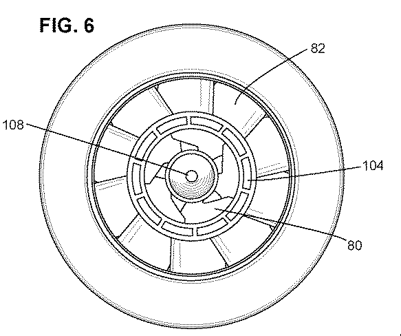
図5〜図7はさらに、図4の燃料−空気ミキサ72を示す図である。図5は、斜視図であり、燃料−空気ミキサ72内に高エネルギー含有量燃料を導入するための燃料噴射オリフィス112を一層よく示している。図5はまた、燃料プレナム84内に低エネルギー含有量燃料を導入するための燃料入口102の1つの実施形態を示している。他の実施形態では、燃料プレナム84は、燃料−空気ミキサ72内への一層均一な燃料噴射プロセスを促進するために、燃料プレナム84の周りに円周方向に配置された複数の燃料入口102を含むことができ、或いは低エネルギー含有量燃料のための別個の円錐形燃料プレナムを設けることができる。本明細書に開示するような低エネルギー含有量燃料は、30MJ/kgよりも小さい低発熱量を有する燃料である。そのような燃料の実施例には、それに限定されないが、H2及びN2の60/40又は50/50混合物、及びシンガスが含まれる。図6及び図7は、図4の燃料−空気ミキサ72のそれぞれ平面図(下流から上流に向って見た)及び底面図(上流から下流に向って見た)であり、外側スワーラ82、第3のスワーラ104(図6)、内側スワーラ80、燃料プレナム84の上流端部100(図7)及び中心体108の相対的位置を示している。
5 to 7 further show the fuel-
燃料シュラウド86から内側スワーラ80及び/又は外側スワーラ82のベーンを通して噴射される高エネルギー含有量燃料のための入口ポートの有効面積、と第3のスワーラ104とが高エネルギー並びに燃料プレナム84から低エネルギー含有量燃料を噴射するための第3のスワーラ104の有効出口面積は、所定の火炎温度を得るための燃空比及び当量比の所定の設計限界値における燃料噴射プロセス、燃料噴射速度及び燃料流量マッハ数に関連した総圧力降下を最小にするような方法での燃料−空気ミキサの作動を可能にし、それによって低エネルギー含有量燃料、高エネルギー含有量燃料及び/又はこれら両燃料の組合せで燃料−空気ミキサ72を作動させるのを可能にするように選択される。加えて、内側及び外側スワーラ80及び82の両方並びに第3のスワーラ104の高エネルギー含有及び/又は低エネルギー含有量燃料を適切に混合する能力により、燃料−空気ミキサ72又は環状シュラウド90内におけるフラッシュバック又は保炎が最少なる及び/又は排除されることになることは、当業者には分かるであろう。
The effective area of the inlet port for high energy content fuel injected from the
下の表Iには、5つの異なるタイプの燃料についての燃料−空気ミキサのパラメータ変化の一例を示しており、この表Iは、5つの異なる燃料についての所定の燃料圧力降下及び2500°F(1371℃)の火炎温度を得るための当量比、燃料質量流量、有効面積、有効面積における%増加、並びに燃料噴射速度及びマッハ数を表で示している。表Iに示した結果の中で、有効面積の%増加は、天然ガスの場合の有効面積に対するものであり、つまり例えば天然ガス及び純水素の場合の有効面積は、それぞれ0.015in2及び0.018in2であるので、天然ガスの場合の有効面積における%増加は、ゼロであり、また水素の場合の有効面積における%増加は、17.8(つまり、17.8=[{(0.018−0.015)/0.015}*100])である。当業者には分かるように、有効面積における%増加は、N2のほかに、それに限定されないが、数例を挙げるとCO2、蒸気のような水分、COなどのようなその他のガスが燃料内に存在しがちであることを考えると、表Iに示された値から変化する可能性がある。 Table I below shows an example of a fuel-air mixer parameter change for five different types of fuel, which shows a predetermined fuel pressure drop for five different fuels and 2500 ° F ( The equivalent ratio, fuel mass flow rate, effective area,% increase in effective area, fuel injection speed and Mach number to obtain a flame temperature of 1371 ° C. are shown in the table. Among the results shown in Table I, the% increase in effective area is relative to the effective area for natural gas, that is, for example, the effective area for natural gas and pure hydrogen is 0.015 in 2 and 0, respectively. Since .018 in 2 , the% increase in effective area for natural gas is zero and the% increase in effective area for hydrogen is 17.8 (ie 17.8 = [{(0. 018-0.015) /0.015} * 100]). As will be appreciated by those skilled in the art, the% increase in effective area is not limited to N 2 , but to some extent other gases such as CO 2 , moisture like steam, CO etc. May vary from the values shown in Table I.
表Iに示すように、低エネルギー含有量燃料がH2及びN2の60/40又は50/50混合物である場合には、燃料プレナム84の有効面積は、2500°F(1371℃)の火炎温度を得るためには、高エネルギー含有量燃料を噴射するための燃料シュラウド86の入口ポートの有効面積よりもそれぞれ約4.67倍及び7.13倍大きくすべきである。シンガスの場合には、燃料プレナム84の有効面積は、燃料シュラウド86の入口ポートの有効面積よりも約12倍大きくすべきである。純H2の場合には、燃料シュラウド86の入口ポートの有効面積は、高エネルギー含有量燃料として天然ガスを使用する時のその有効面積よりも約1.78倍大きい。純水素を含むH2含有燃料の場合には、水素の質量流量は、0.012〜0.015lbm/secでのみ変化し、これは考察した異なる燃料について、(1)水素質量流量は、同程度の大きさであり、(2)水素のみが噴射される場合、燃料噴射孔における圧力降下は、全ての燃料について同じ範囲内にあることになり、また(3)水素及びその他の混合物(N2又はN2/CO)は、許容可能な圧力損失での燃料フレキシビリティを得るために、別々に噴射しかつ後で燃料−空気ミキサ内で空気と混合することができることを示している。
As shown in Table I, when the low energy content fuel is a 60/40 or 50/50 mixture of H 2 and N 2 , the effective area of the
2000°F〜3000°F(つまり、1093℃〜1649℃)の範囲にある火炎温度を得るために、H2及びN2の60/40又は50/50混合物低エネルギー含有量燃料の場合の燃料プレナム84の有効面積の範囲は、高エネルギー含有量燃料としての天然ガスを噴射するための燃料シュラウド86の入口ポートの有効面積よりも、それぞれ約4.2〜4.6倍及び6.43〜8.57倍大きい。シンガスの場合には、同一の火炎温度範囲を得るためには、燃料プレナム84の有効面積は、燃料シュラウド86の入口ポートの有効面積の約10.82〜14.43倍大きい範囲にすべきである。純水素の場合には、燃料シュラウド86の入口ポートの有効面積の範囲は、指定範囲内の火炎温度を得るために、高エネルギー含有量燃料として天然ガスを使用する時のその有効面積よりも約1.6倍〜約2.14倍大きい。
Fuel in the case of a 60/40 or 50/50 mixture low energy content fuel of H 2 and N 2 to obtain a flame temperature in the range of 2000 ° F. to 3000 ° F. (ie 1093 ° C. to 1649 ° C.) The effective area range of the
シンガスを用いて作動させる難しさは、天然ガスと同じ燃焼速度を得るために必要な高い体積流量と関係している。このような状況では、燃料流れ面積は、シンガスの組成に基づいて10〜15倍だけ拡大させる必要がある。加えて、シンガスのウォッベ指数は、天然ガスのウォッベ指数よりも大幅に低い。使用中に、燃料−空気ミキサ72は、内側及び外側二重反転空気スワーラ80及び82の使用により、ヘリカルスワーラ104を介して導入されたシンガスのような低エネルギー含有量燃料を剪断して、燃料−空気混合気が旋回運動状態で燃焼チャンバプレナムに送給される前に、内側及び外側スワーラを通って流れる空気と適切に混合するのを保証する。
The difficulty of operating with syngas is related to the high volume flow required to obtain the same burning rate as natural gas. In such a situation, the fuel flow area needs to be increased by 10-15 times based on the syngas composition. In addition, Syngas' Wobbe index is significantly lower than that of natural gas. In use, the fuel-
本発明の技術による別の実施形態では、図8に示すように、中心体108はさらに、内側スワーラ80と流れ連通した複数のオリフィス114と流体連通した、高エネルギー含有量燃料用の環状通路113を含むことができる。中心体内に付加的な燃料入口オリフィスを設けることは、燃料−空気ミキサ72内における混合の度合いを高めることのなることは、当業者には分かるであろう。図示していないが、別の実施形態では、複数のオリフィス114は、内側スワーラ80の直ぐ下流に配置して、これらのオリフィスからも燃料を燃料−空気ミキサ72内に噴射することができるのが好ましい。燃料−空気ミキサ72内にガス状及び液状燃料を噴射する場合には、ガス状燃料は、スワーラベーン通路及びオリフィス112を通して噴射させ、また液状燃料は、内側スワーラ80の下流で中心体108内に配置したオリフィスを通して噴射させるようにするのが好ましいが分かるであろう。従って、燃料タイプの変更は、中心体108内に配置されたオリフィスを通して噴射する燃料の量を増大させると同時に、それに対応させてベーンを通して噴射する燃料の量を減少させることによって、予想以上に迅速かつ簡単に達成することができる。別の実施形態(図示せず)では、中心体108は、中心体の先端を貫通して、比較的高い軸方向速度の空気を中心体108に隣接した燃焼チャンバ76内に導入する通路を含むことができるのが好ましく、この特定の実施形態では、局所的な燃料/空気比を低下させて、火炎を中心体先端の下流に押しやるのを助けることができる。
In another embodiment in accordance with the present technique, as shown in FIG. 8, the
本発明の技術によるさらに別の実施形態では、図9に示すように、燃料−空気ミキサ72は、燃料シュラウド86と環状シュラウド90との間に半径方向スワーラ116を含む。内側又は外側スワーラ80及び82のいずれか内に導入された燃料は、環状シュラウド90の表面に向って集まる傾向があり、従って環状シュラウド90の下流端部96において燃料の高濃度の領域を生じさせる可能性がある。この環状シュラウド90の出口付近の高い燃料濃度は、環状シュラウド90内へのフラッシュバックの可能性を増大させるのみならず、燃焼チャンバ76内で形成されるNOxの量も増加させる可能性がある。半径方向スワーラ116の有利な特徴の1つは、半径方向スワーラ116を通して導入された空気により、環状シュラウド90の表面付近における燃料空気の混合が強化され、それによって環状シュラウド90の出口における高い燃料濃度を有する領域が減少及び/又は排除され、従って燃焼チャンバ76内で形成されるNOxの総量が低減することである。図10は、半径方向スワーラ116の斜視図を示している。
In yet another embodiment in accordance with the present technique, the fuel-
図10に示すように、半径方向スワーラ116は、外表面122上に配置された複数のベーン120を有する、その上流端部に配置された第1のリング118を含む。各ベーン120は、各ベーン120の各第1の端部部分つまり後縁124が、第1のリング118の外端縁部126に隣接して位置した各ベーン120の第2の端部部分つまり前縁125の半径方向内側に設置された状態で、外表面122上で燃料−空気ミキサ72の軸方向軸線Aの周りで円周方向に延びるように配置される。図示するように、第1のリング118はまた、第1のリング118の内端縁部から軸方向に延びる環状リップ128を含む。半径方向スワーラ116の別の部品は、第1のリング118から離れて軸方向に配置されて半径方向及び軸方向の両方向に沿って延びるギャップをそれらの間に形成した第2のリング130である。図示するように、第2のリング130の第1の表面132は、半径方向内向きに延びて第1のリング118の外表面122との間に半径方向に延びるギャップ134を形成し、このギャップ134に複数のベーン120が配置される。第2のリング130の第2の表面136は、第1のリング118の環状リップ128との間に軸方向に延びるギャップ138を形成するように軸方向に延びる。第2のリング130はまた、スリーブ140を含み、このスリーブ140の内側には、燃料−空気ミキサ72を組立てている時に燃料−空気ミキサ72の環状シュラウド90が配置される。
As shown in FIG. 10, the
内側及び外側スワーラ80及び82の位置に対する燃料−空気ミキサ72に沿った半径方向スワーラ116の軸方向位置並びに/或いは半径方向スワーラ92から出る空気流の半径方向回転の程度は、特に環状シュラウド92の壁に隣接した領域内の燃料−空気ミキサ72の下流端部110における燃料−空気混合気の所望の混合レベルに基づいて決定することができる。加えて、半径方向スワーラ116の幾何学形状及び寸法は、それに限定されないが、燃料圧力、燃料温度、流入空気温度及び燃料噴射速度などの因子を含む所望の予混合効率及び作動条件に基づいて選択/最適化することができる。燃料の実施例には、天然ガス、高水素ガス、水素、バイオガス、一酸化炭素及び合成ガスが含まれる。しかしながら、様々な他の燃料もまた使用することができる。
The axial position of the
図4〜図10において本明細書に開示した燃料−空気ミキサの有利な特徴は、本明細書に例示した実施形態に加えて、別の組合せにおいても使用できることは、当業者には分かるであろう。例えば、開示した発明の技術的範囲内にある開示した燃料−空気ミキサの別の実施形態は、中心体を通しての燃料の導入がない状態で半径方向スワーラと組合せた第3のスワーラを含むことができる。加えて、開示した設計及びそれらの均等物は、上に説明したように、異なるタイプの燃料での作動において使用されることになることが、分かるであろう。例えば、高エネルギー含有量燃料は、開示した高エネルギー含有量燃料噴射ポートを通して噴射された天然ガス及び/又は純水素のいずれかとすることができる。別の実施形態では、燃料−空気ミキサは、開示した低エネルギー含有量燃料噴射ポートを介して供給されたH2/N2の混合物又はシンガス(H2/CO/N2)で作動させることができる。これらの燃料−空気ミキサはまた、最高100%まで予混合した部分的予混合モードとしてシンガス燃焼のために使用し、それによって現行のIGCC燃焼システムと比べて低NOx燃焼を保証することができる。そのようなミキサは、100%水素からCO/H2/N2と水蒸気又はCO2のような別の不活性ガスとの混合物までを燃焼させるように設計されたノズルを組み込んで、NOxの制御のために何らの水蒸気噴射も必要としない状態で、部分又は完全予混合モードとしてシンガスで作動することになる。 Those skilled in the art will appreciate that the advantageous features of the fuel-air mixer disclosed herein in FIGS. 4-10 can be used in other combinations in addition to the embodiments illustrated herein. Let's go. For example, another embodiment of the disclosed fuel-air mixer within the scope of the disclosed invention may include a third swirler in combination with a radial swirler with no introduction of fuel through the central body. it can. In addition, it will be appreciated that the disclosed designs and their equivalents will be used in operation with different types of fuel, as described above. For example, the high energy content fuel can be either natural gas and / or pure hydrogen injected through the disclosed high energy content fuel injection port. In another embodiment, the fuel-air mixer may be operated with a H 2 / N 2 mixture or syngas (H 2 / CO / N 2 ) supplied via the disclosed low energy content fuel injection port. it can. These fuel-air mixers can also be used for syngas combustion as a partial premix mode premixed up to 100%, thereby ensuring low NOx combustion compared to current IGCC combustion systems. Such a mixer incorporates a nozzle designed to burn from 100% hydrogen to a mixture of CO / H 2 / N 2 and another inert gas such as water vapor or CO 2 to control NOx. Will operate with syngas as a partial or fully premixed mode without requiring any steam injection.
上記の燃料−空気ミキサ72の実施形態は、統合型ガス化複合サイルルすなわちIGCCで使用するのに特に適しており、このIGCCは、石炭などの固体燃料のガス化によって得た燃料の燃焼によって駆動されるガスタービンを有すると同時に、ガスタービンからの排出ガスを水/蒸気と熱交換して蒸気タービンを駆動する過熱蒸気を生成するサイクルである。IGCCプラントのガス化部分は、ガス化装置内で石炭を酸素と組合せて気体燃料、すなわち主に水素及び一酸化炭素、又は合成ガスを生成することによって精炭ガスを生産する。次にガス清浄化プロセスにより合成ガスを清浄化し、この合成ガスは、続いて電気を生成するためにガスタービンの燃焼器で用いられる。IGCCプラントは一般的に、より高い出力と共により高い効率及びより低いエミッションを有する。より高い出力は、空気分離ユニットすなわちASUから得た窒素をガスタービンの燃焼器内に導入し、それによってガスタービンを通る質量流量を増加させ、かつ燃焼に用いる空気の減少によって全体的な燃焼温度及び酸素濃度を低下させた時に、達成される。開示した本発明の実施形態による燃料−空気ミキサ72は、IGCCプラントで使用するのに適している。具体的には、燃料−空気ミキサ72は、ガスタービン燃焼器内で使用することができ、窒素は、合成ガスを燃焼させる時に半径方向スワーラ116内に導入し、従って壁近くでの高い燃料濃度を減少させかつ燃料空気混合特性を強化するのを助けることができる。この半径方向スワーラはまた、高水素の燃焼時に窒素がシュラウドを通って流れかつシュラウド内で水素及び空気と混合することができるように使用して、この場合にも燃料−空気ミキサの出口における局所的高当量比領域を回避することができる。
The embodiment of the fuel-
典型的なIGCCガスタービン燃焼器では、水素及び窒素は、同時に内側スワーラ80及び外側スワーラ82内の燃料噴射ポートを通して導入される。開示した実施形態の幾つかでは、水素を窒素と混合しかつ燃料ポートを通してその混合気を導入することに代えて、水素を燃料ポートに供給しかつ窒素を半径方向スワーラによって噴射するか又は流入空気と共に供給するかのかのいずれかし、従って酸素の全体的な利用を減少させるように空気を減少させ、それによって従来のレベルと比較して70%ほどもNOxレベルを低下させる。本発明の実施形態の1つでは、燃焼器の出口におけるNOxレベルは、3〜5ppm又はそれより低い。そのような性能の向上は、空気を減少させることにより、燃料−空気ミキサ72の環状シュラウド90内での耐フラッシュバック性及び耐火炎保持性を強化した状態で達成される。いずれにせよ、上記に要約した利点はIGCCプラントにおいては明らかであるが、開示した燃料−空気ミキサが、発電ガスタービンの現在の燃焼器を改造するために使用することができることは、当業者には分かるであろう。
In a typical IGCC gas turbine combustor, hydrogen and nitrogen are simultaneously introduced through fuel injection ports in the
上述の燃料−空気ミキサはまた、システムの燃焼器内での反応に先だって酸素及び天然ガスを予混合するのを強化するために、気体液体化システムで使用することができる。一般的に、気体液体化システムは、空気分離ユニット、ガス処理ユニット及び燃焼器を含む。作動中に、空気分離ユニットは、空気から酸素を分離し、またガス処理ユニットは、燃焼器内での変換のための天然ガスを調製する。空気分離ユニットからの酸素及びガス処理ユニットからの天然ガスは、燃焼器に導かれ、燃焼器において、天然ガス及び酸素が、高温及び高圧で反応して合成ガスを生成する。この実施形態では、燃料−空気ミキサは、燃焼器に連結されて、燃焼器内での反応に先立って酸素及び天然ガスを予混合するのを可能にする。さらに、燃料−空気ミキサの半径方向スワーラ92は、流入天然ガスを同伴するのを可能にして、滞留時間を最小にしながら合成ガス生産収率を最大化するように高い燃料対酸素当量比(例えば約3.5から最大約4及びそれ以上)での天然ガス及び酸素の混合を可能にする。一部の実施形態では、酸素又は燃料に蒸気を加えて、プロセス効率を高めることができる。
The fuel-air mixer described above can also be used in a gas liquefaction system to enhance premixing of oxygen and natural gas prior to reaction in the combustor of the system. In general, a gas liquefaction system includes an air separation unit, a gas processing unit, and a combustor. During operation, the air separation unit separates oxygen from the air, and the gas processing unit prepares natural gas for conversion in the combustor. Oxygen from the air separation unit and natural gas from the gas processing unit are directed to a combustor where the natural gas and oxygen react at high temperatures and pressures to produce synthesis gas. In this embodiment, a fuel-air mixer is connected to the combustor to allow premixing of oxygen and natural gas prior to reaction in the combustor. In addition, the fuel-air mixer
次にシンガス(合成ガス)は、急冷しかつフィッシャー・トロプシュ処理ユニットに導入し、このフィッシャー・トロプシュ処理ユニットにおいて触媒作用によって水素ガス及び一酸化炭素を長鎖液体炭化水素に再結合させる。最後に、液体炭化水素は、クラッキングユニット内において製品に分留変換される。半径方向スワーラを有する燃料−空気ミキサは、天然ガス及び酸素の速やかな予混合並びに実質的に気体液体化システム内の短い滞留時間を生じさせる利点がある。 The syngas (syngas) is then quenched and introduced into a Fischer-Tropsch processing unit where hydrogen gas and carbon monoxide are recombined into long-chain liquid hydrocarbons by catalysis. Finally, liquid hydrocarbons are fractionally converted to product in the cracking unit. A fuel-air mixer with a radial swirler has the advantage of producing rapid premixing of natural gas and oxygen and a substantially short residence time in the gas liquefaction system.
以上に説明した本方法の様々な態様は、ガスタービン及び炉などの加熱装置で使用する燃焼器のような様々な用途において実用性を有する。さらに、本明細書に記載した方法は、燃焼に先立って燃料及び空気の予混合を強化し、それによって実質的にガスタービンシステムのエミッションを低減しかつ効率を高める。予混合法は、それに限定されないが、天然ガス、炭化水素、一酸化炭素、水素、バイオガス及び合成ガスを含む高い及び低い容積発熱量のガス状化石燃料のような様々な燃料に使用することができる。従って、既に説明したように、燃料−空気ミキサは、統合型ガス化複合サイクル(IGCC)の燃料フレキシブル燃焼器において、汚染物質の排出を低減するために使用することができる。一部の実施形態では、燃料−空気ミキサは、航空転用及び重作業機械用の航空機エンジン水素燃焼器及び他のガスタービン燃焼器で使用される。さらに、燃料−空気ミキサは、特に二酸化炭素フリーサイクル及び排出ガス再循環に有用なものとなる、酸素−燃料などのストリームの部分的混合を可能にするために利用することができる。 The various aspects of the method described above have utility in various applications such as combustors for use in heating devices such as gas turbines and furnaces. Further, the method described herein enhances fuel and air premixing prior to combustion, thereby substantially reducing gas turbine system emissions and increasing efficiency. The premixing method should be used for various fuels such as high and low volumetric calorific fossil fuels including but not limited to natural gas, hydrocarbons, carbon monoxide, hydrogen, biogas and synthesis gas. Can do. Thus, as already explained, fuel-air mixers can be used to reduce pollutant emissions in an integrated gasification combined cycle (IGCC) fuel flexible combustor. In some embodiments, fuel-air mixers are used in aircraft engine hydrogen combustors and other gas turbine combustors for aeroderivative and heavy duty machinery. In addition, fuel-air mixers can be utilized to enable partial mixing of streams such as oxy-fuel, which are particularly useful for carbon dioxide free cycles and exhaust gas recirculation.
従って、上述の付加的半径方向スワーラに基づいた予混合法は、燃焼器内の予混合及び火炎安定性を高めるのを可能にする。さらに、本方法は、エミッション、特にそのような燃焼器からのNOxエミッションの低減を可能にし、それによって環境に優しい状態でガスタービンの運転を行う。一部の実施形態では、本方法は、燃焼器、より具体的には水素燃焼器における圧力降下を最小にするのを可能にする。加えて、付加的半径方向スワーラによって達成された予混合の強化により、燃焼器のターンダウンの強化、耐フラッシュバック性の強化及びフレームアウト・マージンの増大を可能にする。 Thus, the premixing method based on the additional radial swirler described above makes it possible to increase the premixing and flame stability in the combustor. In addition, the method allows for a reduction in emissions, particularly NOx emissions from such combustors, thereby operating the gas turbine in an environmentally friendly manner. In some embodiments, the method allows minimizing pressure drop in the combustor, more specifically in the hydrogen combustor. In addition, the enhanced premixing achieved by the additional radial swirler enables enhanced combustor turndown, enhanced flashback resistance, and increased frameout margin.
この例示した実施形態では、燃料及び空気の良好な混合により、良好なターンダウンを可能にし、また約0.2もの低い当量比を有する天然ガス及び空気混合気での運転を可能にする。加えて、フレームアウト・マージンは、既存のシステムと比較して著しく改善される。さらに、前に記載したように、このシステムは、様々な燃料で使用することができ、従って高い燃料フレキシビリティをもたらす。例えば、上記したような有効面積の範囲は、本システムが例えば高エネルギー含有量燃料として天然ガスもしくはH2を、及び/又は低エネルギー含有量燃料としてシンガスのいずれかを使用することを可能にする。そのようなシステムの燃料フレキシビリティは、異なる燃料を必要とする異なる燃料ポートを備えたハードウェアの変更又は複雑なアーキテクチャの必要性を排除する。上述のように、記載した燃料−空気ミキサは、様々な燃料で使用することができ、従ってシステムの燃料フレキシビリティをもたらす。その上、上述の方法は、既存のカン型又はカン−アニュラ型燃焼器で使用して、エミッション並びに燃焼器内のあらゆるダイナミック振動及び変調を低減することができる。さらに、この例示した装置は、既存の燃焼器内のパイロットとして使用することができる。 In this illustrated embodiment, good mixing of fuel and air allows for good turndown and allows operation with natural gas and air mixtures having an equivalence ratio as low as about 0.2. In addition, the frame-out margin is significantly improved compared to existing systems. Moreover, as previously described, this system can be used with a variety of fuels, thus providing high fuel flexibility. For example, the range of the effective area as described above, makes it possible to use one of syngas to natural gas or H 2 as the system is for example a high energy content fuel, and / or as a low energy content fuel . The fuel flexibility of such a system eliminates the need for hardware changes or complex architectures with different fuel ports that require different fuels. As mentioned above, the described fuel-air mixer can be used with a variety of fuels, thus providing fuel flexibility of the system. Moreover, the method described above can be used with existing can-type or can-annular combustors to reduce emissions and any dynamic vibration and modulation within the combustor. Furthermore, the illustrated apparatus can be used as a pilot in an existing combustor.
燃焼システム内で高エネルギー含有量燃料又は低エネルギー含有量燃料と酸化剤とを予混合する方法もまた、開示した本発明の実施形態の技術的範囲内であり、そのような方法は、その酸化剤入口を通して第1の酸化剤ストリームを燃料−空気ミキサの環状シュラウド内に取り込む段階と、外側スワーラ内で第1の酸化剤ストリームの第1の部分を第1の方向に旋回させる段階と、内側スワーラ内で第1の酸化剤ストリームの第2の部分を第1の方向とは反対である第2の方向に旋回させる段階と、外側スワーラ内の燃料入口オリフィスと流体連通した燃料シュラウドから燃料−空気ミキサ内に高エネルギー含有量燃料を噴射する段階、又は軸方向に延びてそれらの間にギャップを形成する内側及び外側シュラウドによって形成されたアニュラス、その上流部分に配置された少なくとも1つの燃料入口並びにその下流部分において内側及び外側シュラウド間に形成されたギャップ内に配置された燃料プレナムスワーラを含み、その内側シュラウドが内側スワーラの外側円周方向端部部分の周りで円周方向に配置された燃料プレナムから、燃料−空気ミキサ内に低エネルギー含有量燃料を噴射する段階とを含む。 Methods for premixing high energy content fuels or low energy content fuels and oxidants in a combustion system are also within the scope of the disclosed embodiments of the invention, and such methods include the oxidation thereof. Entraining the first oxidant stream through the oxidant inlet into the annular shroud of the fuel-air mixer, swirling the first portion of the first oxidant stream in the first direction within the outer swirler, Swirling a second portion of the first oxidant stream in a swirler in a second direction opposite to the first direction, and fuel-from a fuel shroud in fluid communication with a fuel inlet orifice in the outer swirler Injecting high energy content fuel into an air mixer, or an annulus formed by inner and outer shrouds extending axially to form a gap therebetween A fuel plenum swirler disposed in a gap formed between the inner and outer shrouds at the downstream portion and at least one fuel inlet disposed at the upstream portion thereof, the inner shroud being an outer circumference of the inner swirler Injecting low energy content fuel into a fuel-air mixer from a fuel plenum disposed circumferentially around a directional end portion.
上記の説明に関して、寸法、形態機能並びに作動、組立及び用途の状態における変更を含む本発明の部品についての最適な寸法関係は、当業者には容易に明らかかつ自明であると考えられ、従って、図面に示しかつ明細書に説明したものと均等な全ての関係は、特許請求の範囲の技術的範囲によってのみ包含されることになるように意図していることを理解されたい。加えて、本発明は、現在実用的でありかつ本発明の幾つかの例示的な実施形態であると考えられるものに関して具体的にかつ詳細に図面に示しかつ上記に十分に説明してきたが、本明細書に記載した原理及び概念から逸脱せずにそれら実施形態の多くの変更を行うことができることは、当業者には明らかであろう。従って、本発明の適切な技術的範囲は、全てのそのような変更及び均等物を包含するように特許請求の範囲を最も広く解釈することによってのみ決定されるべきである。 With regard to the above description, the optimal dimensional relationships for the components of the present invention, including changes in dimensions, form functions and operation, assembly and application conditions, would be readily apparent and obvious to those skilled in the art, and thus It should be understood that all relationships equivalent to those shown in the drawings and described in the specification are intended to be embraced only by the scope of the claims. In addition, while the present invention has been shown in particular and in detail in the drawings and fully described above with respect to what is presently practical and considered to be several exemplary embodiments of the present invention, It will be apparent to those skilled in the art that many changes can be made in the embodiments without departing from the principles and concepts described herein. Accordingly, the proper scope of the invention should be determined only by interpreting the scope of the claims in the broadest manner so as to encompass all such modifications and equivalents.
Claims (10)
環状シュラウドの軸方向軸線に沿って延びる中心体と、
中心体の外表面の周りに配置された内側円周方向端部部分を有し、環状シュラウドの上流端部部分に配置された内側スワーラと、
軸方向に延びてそれらの間にギャップを形成する内側及び外側シュラウドによって形成されたアニュラス、燃料入口、並びにその下流部分において内側及び外側シュラウド間に形成されたギャップ内に配置された燃料プレナムスワーラを有し、内側シュラウドが内側スワーラの外側円周方向端部部分の周りで円周方向に配置された燃料プレナムと、
燃料プレナムの外側シュラウドの周りに配置された内側円周方向端部部分を有する外側スワーラと、
環状シュラウドの上流端部部分において外側スワーラの半径方向外側でかつ環状シュラウドの周りで円周方向に配置され、外側スワーラ内の複数の燃料噴射ポートと流体連通した燃料シュラウドと、を含み、
内側及び外側スワーラが、環状シュラウドの上流端部部分において環状シュラウドに流入する第1の酸化剤ストリームのそれぞれ第1及び第2の部分の独立した回転を可能にするように構成される、
燃料−空気ミキサ。 An annular shroud having an axial axis extending along the axial direction, a radial axis extending along the radial direction, and upstream and downstream end portions;
A central body extending along the axial axis of the annular shroud;
An inner swirler having an inner circumferential end portion disposed around an outer surface of the central body and disposed at an upstream end portion of the annular shroud;
An annulus formed by inner and outer shrouds extending axially to form a gap therebetween, a fuel inlet, and a fuel plenum swirler disposed in a gap formed between the inner and outer shrouds at a downstream portion thereof. A fuel plenum having an inner shroud disposed circumferentially around an outer circumferential end portion of the inner swirler;
An outer swirler having an inner circumferential end portion disposed around an outer shroud of the fuel plenum;
A fuel shroud disposed radially at and around the outer swirler at an upstream end portion of the annular shroud and in fluid communication with a plurality of fuel injection ports in the outer swirler;
Inner and outer swirlers are configured to allow independent rotation of the first and second portions, respectively, of the first oxidant stream flowing into the annular shroud at the upstream end portion of the annular shroud.
Fuel-air mixer.
燃料プレナムスワーラの有効面積が、2000°F〜3000°F(又は、1093℃〜1649℃)の範囲にある火炎温度を得るために、天然ガスを噴射するための外側スワーラ内の複数の燃料噴射ポートの有効面積よりも約6.43〜約8.57倍大きい範囲にある、
請求項4記載の燃料−空気ミキサ。 The low energy content fuel is a 50/50 mixture of hydrogen and nitrogen or the high energy content fuel is natural gas;
Multiple fuel injections in the outer swirler for injecting natural gas to obtain a flame temperature in which the effective area of the fuel plenum swirler is in the range of 2000 ° F to 3000 ° F (or 1093 ° C to 1649 ° C) In a range of about 6.43 to about 8.57 times greater than the effective area of the port;
The fuel-air mixer according to claim 4.
燃料プレナムスワーラの有効面積が、2000°F〜3000°F(又は、1093℃〜1649℃)の範囲にある火炎温度を得るために、天然ガスを噴射するための外側スワーラ内の複数の燃料噴射ポートの有効面積よりも約4.2〜約5.6倍大きい範囲にある、
請求項4記載の燃料−空気ミキサ。 The low energy content fuel is a 60/40 mixture of hydrogen and nitrogen or the high energy content fuel is natural gas;
Multiple fuel injections in the outer swirler for injecting natural gas to obtain a flame temperature in which the effective area of the fuel plenum swirler is in the range of 2000 ° F to 3000 ° F (or 1093 ° C to 1649 ° C) In the range of about 4.2 to about 5.6 times larger than the effective area of the port;
The fuel-air mixer according to claim 4.
燃料プレナムスワーラの有効面積が、2000°F〜3000°F(又は、1093℃〜1649℃)の範囲にある火炎温度を得るために、天然ガスを噴射するための外側スワーラ内の複数の燃料噴射ポートの有効面積よりも約10.82〜約14.43倍大きい範囲にある、
請求項4記載の燃料−空気ミキサ。 The low energy content fuel is syngas or the high energy content fuel is natural gas;
Multiple fuel injections in the outer swirler for injecting natural gas to obtain a flame temperature in which the effective area of the fuel plenum swirler is in the range of 2000 ° F to 3000 ° F (or 1093 ° C to 1649 ° C) In the range of about 10.82 to about 14.43 times greater than the effective area of the port;
The fuel-air mixer according to claim 4.
純水素を噴射するための外側スワーラ内の複数の燃料噴射ポートの有効面積が、高エネルギー含有量燃料が天然ガスである場合における同じ有効面積よりも約1.6〜約2.14倍大きい範囲にある、
請求項4記載の燃料−空気ミキサ。 The high energy content fuel is pure hydrogen,
The effective area of multiple fuel injection ports in the outer swirler for injecting pure hydrogen is about 1.6 to about 2.14 times greater than the same effective area when the high energy content fuel is natural gas It is in,
The fuel-air mixer according to claim 4.
その酸化剤入口を通して第1の酸化剤ストリームを燃料−空気ミキサの環状シュラウド内に取り込む段階と、
外側スワーラ内で第1の酸化剤ストリームの第1の部分を第1の方向に旋回させる段階と、
内側スワーラ内で第1の酸化剤ストリームの第2の部分を第1の方向とは反対である第2の方向に旋回させる段階と、
外側スワーラ内の燃料入口オリフィスと流体連通しておりかつ外側及び内側スワーラが設置されているのと略同一の軸方向位置に配置された燃料シュラウドから、燃料−空気ミキサ内に高エネルギー含有量燃料を噴射する段階、又は、軸方向に延びてそれらの間にギャップを形成する内側及び外側シュラウドによって形成されたアニュラス、その上流部分に配置された燃料入口並びにその下流部分において内側及び外側シュラウド間に形成されたギャップ内に配置された燃料プレナムスワーラを有し、その内側シュラウドが内側スワーラの外側円周方向端部部分の周りで円周方向に配置された燃料プレナムから、燃料−空気ミキサ内に低エネルギー含有量燃料を噴射する段階と、
を含む方法。 A method of premixing a high energy content fuel or a low energy content fuel with an oxidant in a combustion system comprising:
Taking the first oxidant stream through the oxidant inlet into the annular shroud of the fuel-air mixer;
Swiveling a first portion of the first oxidant stream in a first direction within the outer swirler;
Swiveling a second portion of the first oxidant stream in an inner swirler in a second direction opposite to the first direction;
A high energy content fuel in a fuel-air mixer from a fuel shroud that is in fluid communication with a fuel inlet orifice in the outer swirler and located at approximately the same axial position as the outer and inner swirlers are installed. Or an annulus formed by inner and outer shrouds extending axially to form a gap therebetween, a fuel inlet disposed in an upstream portion thereof, and an inner portion and an outer shroud in a downstream portion thereof From a fuel plenum having a fuel plenum swirler disposed within the formed gap, the inner shroud circumferentially disposed about the outer circumferential end portion of the inner swirler, and into the fuel-air mixer. Injecting low energy content fuel;
Including methods.
燃料シュラウド並びに内側及び外側スワーラの軸方向位置の下流に配置された半径方向スワーラ内で、環状シュラウドの外側の領域から取り込んだ第2のガス状ストリームを旋回させ、それによって環状シュラウドの出口における環状シュラウドの壁付近の燃料濃度を制御するようにする段階と、
をさらに含む、請求項9記載の方法。 Entraining a second gaseous stream into the annular shroud;
A second gaseous stream taken from a region outside the annular shroud is swirled within the fuel shroud and a radial swirler disposed downstream of the axial position of the inner and outer swirlers, thereby annular at the outlet of the annular shroud. Trying to control the fuel concentration near the shroud wall;
The method of claim 9, further comprising:
Applications Claiming Priority (2)
| Application Number | Priority Date | Filing Date | Title |
|---|---|---|---|
| US11/621,705 | 2007-01-10 | ||
| US11/621,705 US20080163627A1 (en) | 2007-01-10 | 2007-01-10 | Fuel-flexible triple-counter-rotating swirler and method of use |
Publications (2)
| Publication Number | Publication Date |
|---|---|
| JP2008170146A true JP2008170146A (en) | 2008-07-24 |
| JP5330693B2 JP5330693B2 (en) | 2013-10-30 |
Family
ID=39510078
Family Applications (1)
| Application Number | Title | Priority Date | Filing Date |
|---|---|---|---|
| JP2008001733A Expired - Fee Related JP5330693B2 (en) | 2007-01-10 | 2008-01-09 | Fuel flexible triple reversal swirler and method of use |
Country Status (6)
| Country | Link |
|---|---|
| US (1) | US20080163627A1 (en) |
| JP (1) | JP5330693B2 (en) |
| KR (1) | KR20080065935A (en) |
| CN (1) | CN101220953B (en) |
| DE (1) | DE102008003300A1 (en) |
| RU (1) | RU2457397C2 (en) |
Cited By (3)
| Publication number | Priority date | Publication date | Assignee | Title |
|---|---|---|---|---|
| JP2012189318A (en) * | 2008-01-29 | 2012-10-04 | Siemens Ag | Burner with fuel nozzle having swirl duct and method for producing fuel nozzle |
| JP2015183892A (en) * | 2014-03-20 | 2015-10-22 | 三菱日立パワーシステムズ株式会社 | Nozzle, burner, combustor, gas turbine, and gas turbine system |
| JP2019512661A (en) * | 2016-03-15 | 2019-05-16 | ケラー,ジェイ | Non-premixed swirl burner tip and combustion strategy |
Families Citing this family (72)
| Publication number | Priority date | Publication date | Assignee | Title |
|---|---|---|---|---|
| US7603841B2 (en) * | 2001-07-23 | 2009-10-20 | Ramgen Power Systems, Llc | Vortex combustor for low NOx emissions when burning lean premixed high hydrogen content fuel |
| US8266911B2 (en) * | 2005-11-14 | 2012-09-18 | General Electric Company | Premixing device for low emission combustion process |
| US20080115500A1 (en) * | 2006-11-15 | 2008-05-22 | Scott Macadam | Combustion of water borne fuels in an oxy-combustion gas generator |
| US8099960B2 (en) * | 2006-11-17 | 2012-01-24 | General Electric Company | Triple counter rotating swirler and method of use |
| US8661779B2 (en) * | 2008-09-26 | 2014-03-04 | Siemens Energy, Inc. | Flex-fuel injector for gas turbines |
| KR101049359B1 (en) * | 2008-10-31 | 2011-07-13 | 한국전력공사 | Triple swirl gas turbine combustor |
| US8443607B2 (en) * | 2009-02-20 | 2013-05-21 | General Electric Company | Coaxial fuel and air premixer for a gas turbine combustor |
| BRPI0925016A8 (en) * | 2009-05-06 | 2017-07-11 | Ramgen Power Systems Llc | TRAPPED VORTEX COMBUSTOR, INTEGRATED PROCESS FOR ENERGY GENERATION AND FUEL SYNTHESIS, AND, GAS TURBINE ENGINE |
| US20100319353A1 (en) * | 2009-06-18 | 2010-12-23 | John Charles Intile | Multiple Fuel Circuits for Syngas/NG DLN in a Premixed Nozzle |
| EP2325542B1 (en) * | 2009-11-18 | 2013-03-20 | Siemens Aktiengesellschaft | Swirler vane, swirler and burner assembly |
| FR2952699B1 (en) * | 2009-11-18 | 2013-08-16 | Snecma | INJECTION SYSTEM FOR TURBOMACHINE COMBUSTION CHAMBER, COMPRISING MEANS FOR INJECTING AND MIXING TWO SEPARATE FUELS |
| DE102009054669A1 (en) * | 2009-12-15 | 2011-06-16 | Man Diesel & Turbo Se | Burner for a turbine |
| US20110162379A1 (en) * | 2010-01-06 | 2011-07-07 | General Electric Company | Apparatus and method for supplying fuel |
| US20110259014A1 (en) * | 2010-04-23 | 2011-10-27 | General Electric Company | Refinery residuals processing for integrated power, water, and chemical products |
| US8752386B2 (en) * | 2010-05-25 | 2014-06-17 | Siemens Energy, Inc. | Air/fuel supply system for use in a gas turbine engine |
| US10054313B2 (en) | 2010-07-08 | 2018-08-21 | Siemens Energy, Inc. | Air biasing system in a gas turbine combustor |
| US9528447B2 (en) | 2010-09-14 | 2016-12-27 | Jason Eric Green | Fuel mixture control system |
| RU2011115528A (en) | 2011-04-21 | 2012-10-27 | Дженерал Электрик Компани (US) | FUEL INJECTOR, COMBUSTION CHAMBER AND METHOD OF OPERATION OF THE COMBUSTION CHAMBER |
| CN104053883B (en) * | 2011-08-22 | 2017-02-15 | 马吉德·托甘 | Method for mixing combustion reactants combusting in gas turbine engine |
| US9421861B2 (en) | 2011-09-16 | 2016-08-23 | Gaseous Fuel Systems, Corp. | Modification of an industrial vehicle to include a containment area and mounting assembly for an alternate fuel |
| US10086694B2 (en) | 2011-09-16 | 2018-10-02 | Gaseous Fuel Systems, Corp. | Modification of an industrial vehicle to include a containment area and mounting assembly for an alternate fuel |
| US9738154B2 (en) | 2011-10-17 | 2017-08-22 | Gaseous Fuel Systems, Corp. | Vehicle mounting assembly for a fuel supply |
| WO2013188880A1 (en) * | 2012-06-15 | 2013-12-19 | Cummins Ip, Inc. | Reductant decomposition and mixing system |
| US9115896B2 (en) * | 2012-07-31 | 2015-08-25 | General Electric Company | Fuel-air mixer for use with a combustor assembly |
| US20140144141A1 (en) * | 2012-11-26 | 2014-05-29 | General Electric Company | Premixer with diluent fluid and fuel tubes having chevron outlets |
| US9404656B2 (en) | 2012-12-17 | 2016-08-02 | United Technologies Corporation | Oblong swirler assembly for combustors |
| US9376985B2 (en) * | 2012-12-17 | 2016-06-28 | United Technologies Corporation | Ovate swirler assembly for combustors |
| US9696066B1 (en) | 2013-01-21 | 2017-07-04 | Jason E. Green | Bi-fuel refrigeration system and method of retrofitting |
| US9765973B2 (en) | 2013-03-12 | 2017-09-19 | General Electric Company | System and method for tube level air flow conditioning |
| US9651259B2 (en) | 2013-03-12 | 2017-05-16 | General Electric Company | Multi-injector micromixing system |
| US9650959B2 (en) | 2013-03-12 | 2017-05-16 | General Electric Company | Fuel-air mixing system with mixing chambers of various lengths for gas turbine system |
| US9528444B2 (en) | 2013-03-12 | 2016-12-27 | General Electric Company | System having multi-tube fuel nozzle with floating arrangement of mixing tubes |
| US9671112B2 (en) | 2013-03-12 | 2017-06-06 | General Electric Company | Air diffuser for a head end of a combustor |
| US9759425B2 (en) * | 2013-03-12 | 2017-09-12 | General Electric Company | System and method having multi-tube fuel nozzle with multiple fuel injectors |
| US9534787B2 (en) | 2013-03-12 | 2017-01-03 | General Electric Company | Micromixing cap assembly |
| USD781323S1 (en) | 2013-03-15 | 2017-03-14 | Jason Green | Display screen with engine control system graphical user interface |
| US10408454B2 (en) | 2013-06-18 | 2019-09-10 | Woodward, Inc. | Gas turbine engine flow regulating |
| US9845744B2 (en) | 2013-07-22 | 2017-12-19 | Gaseous Fuel Systems, Corp. | Fuel mixture system and assembly |
| US9394841B1 (en) | 2013-07-22 | 2016-07-19 | Gaseous Fuel Systems, Corp. | Fuel mixture system and assembly |
| US9482433B2 (en) * | 2013-11-11 | 2016-11-01 | Woodward, Inc. | Multi-swirler fuel/air mixer with centralized fuel injection |
| KR102129052B1 (en) * | 2013-11-12 | 2020-07-02 | 한화에어로스페이스 주식회사 | Swirler assembly |
| US9587833B2 (en) | 2014-01-29 | 2017-03-07 | Woodward, Inc. | Combustor with staged, axially offset combustion |
| EP2944792A1 (en) * | 2014-05-12 | 2015-11-18 | Siemens Aktiengesellschaft | Method for operation a burner and combustion system |
| CN104019448A (en) * | 2014-06-13 | 2014-09-03 | 北京北机机电工业有限责任公司 | Double-layer cyclone device of heater combustor |
| CN104266228B (en) * | 2014-09-22 | 2018-02-09 | 北京华清燃气轮机与煤气化联合循环工程技术有限公司 | Gas-turbine combustion chamber axial direction two-stage swirl nozzle in opposite direction |
| CN104266227A (en) * | 2014-09-22 | 2015-01-07 | 北京华清燃气轮机与煤气化联合循环工程技术有限公司 | Gas turbine combustion chamber axial two-stage swirl nozzle |
| US9428047B2 (en) | 2014-10-22 | 2016-08-30 | Jason Green | Modification of an industrial vehicle to include a hybrid fuel assembly and system |
| US9931929B2 (en) | 2014-10-22 | 2018-04-03 | Jason Green | Modification of an industrial vehicle to include a hybrid fuel assembly and system |
| CN104373963B (en) * | 2014-10-28 | 2016-04-27 | 北京华清燃气轮机与煤气化联合循环工程技术有限公司 | A kind of gas-turbine combustion chamber centerbody fluting swirl nozzle |
| US9885318B2 (en) * | 2015-01-07 | 2018-02-06 | Jason E Green | Mixing assembly |
| CN105650680A (en) * | 2016-01-19 | 2016-06-08 | 西北工业大学 | Head design of combustion chamber of twin-stage premixing ground-based gas turbine |
| KR102236267B1 (en) * | 2016-04-08 | 2021-04-05 | 한화에어로스페이스 주식회사 | Industrial Aombustor |
| US10247106B2 (en) * | 2016-06-15 | 2019-04-02 | General Electric Company | Method and system for rotating air seal with integral flexible heat shield |
| PL230047B1 (en) * | 2016-07-06 | 2018-09-28 | Metal Expert Spolka Z Ograniczona Odpowiedzialnoscia Spolka Jawna | High-temperature gas burner |
| CN110461458B (en) * | 2017-01-06 | 2022-03-04 | Sabic环球技术有限责任公司 | Device for injecting and mixing reactive fluids in a high pressure low density polyethylene process |
| CN107270288B (en) * | 2017-08-07 | 2023-03-14 | 段秀春 | Common-mode synchronous industrial flue gas after-combustion circulating treatment module, device and method |
| US11857933B2 (en) * | 2018-03-09 | 2024-01-02 | Produced Water Absorbents Inc. | Systems, apparatuses, and methods for mixing fluids using a conical flow member |
| KR102065582B1 (en) | 2018-03-16 | 2020-01-13 | 두산중공업 주식회사 | Fuel injection device for gas turbine, fuelnozzle and gas turbinehaving it |
| US10935245B2 (en) * | 2018-11-20 | 2021-03-02 | General Electric Company | Annular concentric fuel nozzle assembly with annular depression and radial inlet ports |
| US11175046B2 (en) * | 2019-05-09 | 2021-11-16 | General Electric Company | Combustor premixer assembly including inlet lips |
| CN111520750B (en) * | 2020-03-25 | 2022-05-20 | 西北工业大学 | Novel combustion chamber head oil injection structure |
| CN111911961B (en) * | 2020-09-02 | 2021-07-06 | 西安交通大学 | Natural gas high-proportion hydrogen-blending combustion burner |
| US20220178544A1 (en) * | 2020-12-09 | 2022-06-09 | Pratt & Whitney Canada Corp. | Method of operating an aircraft engine and fuel system using multiple fuel types |
| CA3102511A1 (en) * | 2020-12-11 | 2022-06-11 | De.Mission Inc. | Combustion burner with fixed vanes |
| CN113324262B (en) * | 2021-06-16 | 2022-10-25 | 哈尔滨工程大学 | Coaxial staged gas fuel combustor head for low emission gas turbine |
| FR3127987A1 (en) * | 2021-10-08 | 2023-04-14 | Centre National De La Recherche Scientifique | Dihydrogen and air injection device |
| CA3233988A1 (en) * | 2021-10-08 | 2023-04-13 | Stephane Raphael Yves RICHARD | Device for injecting dihydrogen and air |
| CN114017773B (en) * | 2021-12-16 | 2022-04-22 | 东营市悦凯石油装备有限公司 | Novel anti-backfire gas mixer for gas generator set |
| US11906165B2 (en) | 2021-12-21 | 2024-02-20 | General Electric Company | Gas turbine nozzle having an inner air swirler passage and plural exterior fuel passages |
| US11815269B2 (en) | 2021-12-29 | 2023-11-14 | General Electric Company | Fuel-air mixing assembly in a turbine engine |
| CN114811581B (en) * | 2022-05-16 | 2023-09-22 | 西安交通大学 | Air-fuel dual-stage high-proportion hydrogen-doped ultralow-nitrogen combustor, method and boiler |
| CN115183276A (en) * | 2022-07-25 | 2022-10-14 | 清航空天(北京)科技有限公司 | Fuel supply assembly, engine combustion chamber structure and engine |
Citations (5)
| Publication number | Priority date | Publication date | Assignee | Title |
|---|---|---|---|---|
| JPH0587340A (en) * | 1991-02-22 | 1993-04-06 | General Electric Co <Ge> | Air-fuel mixer for gas turbine combustor |
| US5251447A (en) * | 1992-10-01 | 1993-10-12 | General Electric Company | Air fuel mixer for gas turbine combustor |
| US5351477A (en) * | 1993-12-21 | 1994-10-04 | General Electric Company | Dual fuel mixer for gas turbine combustor |
| US5778676A (en) * | 1996-01-02 | 1998-07-14 | General Electric Company | Dual fuel mixer for gas turbine combustor |
| JP2006258041A (en) * | 2005-03-18 | 2006-09-28 | Kawasaki Heavy Ind Ltd | Gas turbine combustor and its igniting method |
Family Cites Families (19)
| Publication number | Priority date | Publication date | Assignee | Title |
|---|---|---|---|---|
| US3713588A (en) * | 1970-11-27 | 1973-01-30 | Gen Motors Corp | Liquid fuel spray nozzles with air atomization |
| FR2235274B1 (en) * | 1973-06-28 | 1976-09-17 | Snecma | |
| US5865024A (en) * | 1997-01-14 | 1999-02-02 | General Electric Company | Dual fuel mixer for gas turbine combustor |
| RU2142096C1 (en) * | 1998-01-14 | 1999-11-27 | ОО "ПКФ" Автодорстрой" | Multifuel burner |
| US6389815B1 (en) * | 2000-09-08 | 2002-05-21 | General Electric Company | Fuel nozzle assembly for reduced exhaust emissions |
| US6367262B1 (en) * | 2000-09-29 | 2002-04-09 | General Electric Company | Multiple annular swirler |
| RU2178455C1 (en) * | 2000-11-09 | 2002-01-20 | Государственное унитарное предприятие Научно-производственное объединение "Гидротрубопровод" | Water-coal fuel production process |
| US6453660B1 (en) * | 2001-01-18 | 2002-09-24 | General Electric Company | Combustor mixer having plasma generating nozzle |
| US6596780B2 (en) * | 2001-10-23 | 2003-07-22 | Texaco Inc. | Making fischer-tropsch liquids and power |
| US6779333B2 (en) * | 2002-05-21 | 2004-08-24 | Conocophillips Company | Dual fuel power generation system |
| US6896707B2 (en) * | 2002-07-02 | 2005-05-24 | Chevron U.S.A. Inc. | Methods of adjusting the Wobbe Index of a fuel and compositions thereof |
| US6986255B2 (en) * | 2002-10-24 | 2006-01-17 | Rolls-Royce Plc | Piloted airblast lean direct fuel injector with modified air splitter |
| US6871501B2 (en) * | 2002-12-03 | 2005-03-29 | General Electric Company | Method and apparatus to decrease gas turbine engine combustor emissions |
| JP4065947B2 (en) * | 2003-08-05 | 2008-03-26 | 独立行政法人 宇宙航空研究開発機構 | Fuel / air premixer for gas turbine combustor |
| US6968693B2 (en) * | 2003-09-22 | 2005-11-29 | General Electric Company | Method and apparatus for reducing gas turbine engine emissions |
| RU2270402C1 (en) * | 2004-08-06 | 2006-02-20 | Федеральное Государственное унитарное дочернее предприятие Научно-испытательный центр Центрального института авиационного моторостроения (ФГУДП НИЦ ЦИАМ) | Fuel burner |
| RU2267706C1 (en) * | 2004-10-18 | 2006-01-10 | Михаил Дмитриевич Акульшин | Dual-fuel furnace burner |
| US7690204B2 (en) * | 2005-10-12 | 2010-04-06 | Praxair Technology, Inc. | Method of maintaining a fuel Wobbe index in an IGCC installation |
| JP2007162998A (en) * | 2005-12-13 | 2007-06-28 | Kawasaki Heavy Ind Ltd | Fuel spraying device of gas turbine engine |
-
2007
- 2007-01-10 US US11/621,705 patent/US20080163627A1/en not_active Abandoned
-
2008
- 2008-01-07 DE DE102008003300A patent/DE102008003300A1/en not_active Withdrawn
- 2008-01-09 RU RU2008100057/06A patent/RU2457397C2/en not_active IP Right Cessation
- 2008-01-09 KR KR1020080002566A patent/KR20080065935A/en not_active Application Discontinuation
- 2008-01-09 JP JP2008001733A patent/JP5330693B2/en not_active Expired - Fee Related
- 2008-01-10 CN CN2008100030482A patent/CN101220953B/en not_active Expired - Fee Related
Patent Citations (5)
| Publication number | Priority date | Publication date | Assignee | Title |
|---|---|---|---|---|
| JPH0587340A (en) * | 1991-02-22 | 1993-04-06 | General Electric Co <Ge> | Air-fuel mixer for gas turbine combustor |
| US5251447A (en) * | 1992-10-01 | 1993-10-12 | General Electric Company | Air fuel mixer for gas turbine combustor |
| US5351477A (en) * | 1993-12-21 | 1994-10-04 | General Electric Company | Dual fuel mixer for gas turbine combustor |
| US5778676A (en) * | 1996-01-02 | 1998-07-14 | General Electric Company | Dual fuel mixer for gas turbine combustor |
| JP2006258041A (en) * | 2005-03-18 | 2006-09-28 | Kawasaki Heavy Ind Ltd | Gas turbine combustor and its igniting method |
Cited By (3)
| Publication number | Priority date | Publication date | Assignee | Title |
|---|---|---|---|---|
| JP2012189318A (en) * | 2008-01-29 | 2012-10-04 | Siemens Ag | Burner with fuel nozzle having swirl duct and method for producing fuel nozzle |
| JP2015183892A (en) * | 2014-03-20 | 2015-10-22 | 三菱日立パワーシステムズ株式会社 | Nozzle, burner, combustor, gas turbine, and gas turbine system |
| JP2019512661A (en) * | 2016-03-15 | 2019-05-16 | ケラー,ジェイ | Non-premixed swirl burner tip and combustion strategy |
Also Published As
| Publication number | Publication date |
|---|---|
| RU2008100057A (en) | 2009-07-20 |
| KR20080065935A (en) | 2008-07-15 |
| JP5330693B2 (en) | 2013-10-30 |
| CN101220953B (en) | 2012-06-13 |
| DE102008003300A1 (en) | 2008-07-17 |
| CN101220953A (en) | 2008-07-16 |
| US20080163627A1 (en) | 2008-07-10 |
| RU2457397C2 (en) | 2012-07-27 |
Similar Documents
| Publication | Publication Date | Title |
|---|---|---|
| JP5330693B2 (en) | Fuel flexible triple reversal swirler and method of use | |
| JP5331327B2 (en) | Triple ring reversal swirler | |
| JP4831364B2 (en) | High expansion fuel injection slot jet and method for enhancing mixing in a premixer | |
| JP5663023B2 (en) | Inlet premixer for combustion equipment | |
| US5816049A (en) | Dual fuel mixer for gas turbine combustor | |
| JP6266211B2 (en) | Combustor assembly with vortex retention cavities | |
| EP3679300B1 (en) | Gas turbine combustor assembly with a trapped vortex feature and method of operating a gas turbine combustor | |
| US20100170253A1 (en) | Method and apparatus for fuel injection in a turbine engine | |
| JP2008122067A (en) | Method and apparatus for promoting mixing in premixing device | |
| JP2009047415A (en) | Turbine engine fuel supply device and system | |
| US20160265779A1 (en) | Twin radial splitter-chevron mixer with converging throat | |
| JP2011064447A (en) | Radial inlet guide vane for combustor | |
| EP1835231A1 (en) | Burner in particular for a gas turbine combustor, and method of operating a burner | |
| KR20140082659A (en) | Can-annular combustor with premixed tangential fuel-air nozzles for use on gas turbine engines | |
| JP3620776B2 (en) | Gas turbine combustor for gasification power plant | |
| JP5193088B2 (en) | Combustor and gas turbine |
Legal Events
| Date | Code | Title | Description |
|---|---|---|---|
| A621 | Written request for application examination |
Free format text: JAPANESE INTERMEDIATE CODE: A621 Effective date: 20110106 |
|
| RD04 | Notification of resignation of power of attorney |
Free format text: JAPANESE INTERMEDIATE CODE: A7424 Effective date: 20110106 |
|
| A521 | Written amendment |
Free format text: JAPANESE INTERMEDIATE CODE: A523 Effective date: 20111228 |
|
| A131 | Notification of reasons for refusal |
Free format text: JAPANESE INTERMEDIATE CODE: A131 Effective date: 20120228 |
|
| A521 | Written amendment |
Free format text: JAPANESE INTERMEDIATE CODE: A523 Effective date: 20120523 |
|
| A02 | Decision of refusal |
Free format text: JAPANESE INTERMEDIATE CODE: A02 Effective date: 20121211 |
|
| A521 | Written amendment |
Free format text: JAPANESE INTERMEDIATE CODE: A523 Effective date: 20130409 |
|
| A911 | Transfer to examiner for re-examination before appeal (zenchi) |
Free format text: JAPANESE INTERMEDIATE CODE: A911 Effective date: 20130417 |
|
| TRDD | Decision of grant or rejection written | ||
| A01 | Written decision to grant a patent or to grant a registration (utility model) |
Free format text: JAPANESE INTERMEDIATE CODE: A01 Effective date: 20130702 |
|
| A61 | First payment of annual fees (during grant procedure) |
Free format text: JAPANESE INTERMEDIATE CODE: A61 Effective date: 20130726 |
|
| R150 | Certificate of patent or registration of utility model |
Free format text: JAPANESE INTERMEDIATE CODE: R150 |
|
| LAPS | Cancellation because of no payment of annual fees |