JP4831364B2 - High expansion fuel injection slot jet and method for enhancing mixing in a premixer - Google Patents
High expansion fuel injection slot jet and method for enhancing mixing in a premixer Download PDFInfo
- Publication number
- JP4831364B2 JP4831364B2 JP2007287978A JP2007287978A JP4831364B2 JP 4831364 B2 JP4831364 B2 JP 4831364B2 JP 2007287978 A JP2007287978 A JP 2007287978A JP 2007287978 A JP2007287978 A JP 2007287978A JP 4831364 B2 JP4831364 B2 JP 4831364B2
- Authority
- JP
- Japan
- Prior art keywords
- fuel
- combustor
- wall
- premixing
- premixing device
- Prior art date
- Legal status (The legal status is an assumption and is not a legal conclusion. Google has not performed a legal analysis and makes no representation as to the accuracy of the status listed.)
- Expired - Fee Related
Links
Images


Classifications
-
- F—MECHANICAL ENGINEERING; LIGHTING; HEATING; WEAPONS; BLASTING
- F02—COMBUSTION ENGINES; HOT-GAS OR COMBUSTION-PRODUCT ENGINE PLANTS
- F02K—JET-PROPULSION PLANTS
- F02K3/00—Plants including a gas turbine driving a compressor or a ducted fan
- F02K3/08—Plants including a gas turbine driving a compressor or a ducted fan with supplementary heating of the working fluid; Control thereof
- F02K3/105—Heating the by-pass flow
- F02K3/11—Heating the by-pass flow by means of burners or combustion chambers
-
- F—MECHANICAL ENGINEERING; LIGHTING; HEATING; WEAPONS; BLASTING
- F23—COMBUSTION APPARATUS; COMBUSTION PROCESSES
- F23D—BURNERS
- F23D14/00—Burners for combustion of a gas, e.g. of a gas stored under pressure as a liquid
- F23D14/46—Details, e.g. noise reduction means
- F23D14/62—Mixing devices; Mixing tubes
-
- F—MECHANICAL ENGINEERING; LIGHTING; HEATING; WEAPONS; BLASTING
- F02—COMBUSTION ENGINES; HOT-GAS OR COMBUSTION-PRODUCT ENGINE PLANTS
- F02K—JET-PROPULSION PLANTS
- F02K7/00—Plants in which the working fluid is used in a jet only, i.e. the plants not having a turbine or other engine driving a compressor or a ducted fan; Control thereof
-
- F—MECHANICAL ENGINEERING; LIGHTING; HEATING; WEAPONS; BLASTING
- F23—COMBUSTION APPARATUS; COMBUSTION PROCESSES
- F23R—GENERATING COMBUSTION PRODUCTS OF HIGH PRESSURE OR HIGH VELOCITY, e.g. GAS-TURBINE COMBUSTION CHAMBERS
- F23R3/00—Continuous combustion chambers using liquid or gaseous fuel
- F23R3/28—Continuous combustion chambers using liquid or gaseous fuel characterised by the fuel supply
- F23R3/286—Continuous combustion chambers using liquid or gaseous fuel characterised by the fuel supply having fuel-air premixing devices
Description
本発明の実施形態は、総括的には燃焼器に関し、より具体的には、低エミッション燃焼プロセスにおいて燃料及び酸化剤の混合を強化するための高膨張燃料噴射スロットジェットを備えた予混合装置に関する。 Embodiments of the present invention relate generally to combustors, and more particularly to premixing devices with high expansion fuel injection slot jets to enhance fuel and oxidant mixing in low emission combustion processes. .
歴史的に、燃料からのエネルギーの取り出しは、燃焼器内で拡散律速(diffusion−controlled)(非予混合とも呼ばれる)燃焼として実行されてきており、その場合には、反応物質が最初は分離されており、反応は燃料と酸化剤との間の界面でのみ起こり、界面では混合及び反応の両方が発生する。そのような装置の実施例には、それに限定されないが、幾つかの例を挙げると航空機用ガスタービンエンジン、並びに発電、舶用推進、ガス圧縮、コジェネレーション及び海上作業台船動力における用途用の航空転用ガスタービンが含まれる。そのような燃焼器を設計する際には、技術者は、燃焼器の全体寸法を維持又は減少させ、最大作動温度を上昇させかつ比エネルギー放出率を増大させる継続的要求だけでなく、規制汚染物質の形成及びこれらの環境内への排出(エミッション)を低減する絶え間なく拡大する要求にも挑戦している。関心のある主要な汚染物質の実例には、窒素酸化物(NOx)、一酸化炭素(CO)、未燃焼及び部分燃焼炭化水素、並びに二酸化炭素(CO2)などの温室効果ガスが含まれる。燃焼が発生している間における流体力学的混合、局所化学量論的燃焼と関連するピーク温度、高温を有する領域内での滞留時間、及び酸素利用率への依存のために、流れ内の局所的組成変動を制御するのは困難であるので、拡散律速燃焼器は、所望の高性能レベルを維持しながら現在及び将来のエミッション要件を満たす能力には限界がある。 Historically, the extraction of energy from the fuel has been performed as diffusion-controlled (also called non-premixed) combustion in the combustor, in which case the reactants are initially separated. Reaction occurs only at the interface between the fuel and the oxidant, where both mixing and reaction occur. Examples of such devices include, but are not limited to, aircraft gas turbine engines and aviation for applications in power generation, marine propulsion, gas compression, cogeneration and offshore platform power, to name a few. A diverted gas turbine is included. In designing such a combustor, the engineer must maintain or reduce the overall size of the combustor, increase the maximum operating temperature and increase the specific energy release rate, as well as regulatory pollution. It also challenges the ever-increasing demand to reduce the formation of substances and their emissions into the environment. Examples of major pollutants of interest include nitrogenous oxides (NOx), carbon monoxide (CO), unburned and partially burned hydrocarbons, and greenhouse gases such as carbon dioxide (CO 2 ). Because of the dependence on hydrodynamic mixing during combustion, peak temperature associated with local stoichiometric combustion, residence time in regions with high temperatures, and oxygen utilization, Because it is difficult to control dynamic compositional variations, diffusion limited combustors have limited ability to meet current and future emissions requirements while maintaining the desired high performance level.
近年では、望ましくない汚染物質の排出レベルをさらに低減するために、希薄予混合燃焼器が用いられている。これらの燃焼器では、あらゆる有意な化学反応の発生に先立って、適等な量の燃料及び酸化剤が十分に混合され、従って上述した拡散律速燃焼器の困難性を制御するのを可能にする。しかしながら、燃料及び酸化剤の可燃性混合気が、所望の火炎安定位置の前方に形成されるので、予混合燃焼器設計者は、望ましくない燃焼不安定性を最小化及び/又は排除するために、混合が発生する領域におけるあらゆる流れの剥離及び/又は火炎保持を制御する課題に挑戦し続けている。現在の設計課題にはまた、燃料及び酸化剤の混合が発生する領域の全体長さを制御することと、予混合プロセスと関連する圧力低下を最小にすることとが含まれる。これらの課題は、それに限定されないが、石炭又は他の材料のガス化プロセスにより得られる一酸化炭素及び水素の豊富なガスである、天然ガス、水素、及び合成燃料ガス(シンガスとしても知られている)を含む広範な燃料で適切に作動することができる燃焼器の必要性により、さらに複雑になる。 In recent years, lean premix combustors have been used to further reduce the level of undesirable pollutant emissions. In these combustors, an appropriate amount of fuel and oxidant is well mixed prior to the occurrence of any significant chemical reaction, thus allowing the difficulty of the diffusion limited combustor described above to be controlled. . However, since a combustible mixture of fuel and oxidant is formed in front of the desired flame stable position, the premix combustor designer can minimize and / or eliminate undesirable combustion instabilities. It continues to challenge the challenge of controlling any flow separation and / or flame retention in the region where mixing occurs. Current design challenges also include controlling the overall length of the region where fuel and oxidant mixing occurs and minimizing the pressure drop associated with the premixing process. These challenges include, but are not limited to, natural gas, hydrogen, and synthetic fuel gases (also known as syngas), which are rich in carbon monoxide and hydrogen obtained by the gasification process of coal or other materials. This is further complicated by the need for a combustor that can operate properly with a wide range of fuels.
従来型の予混合バーナは、スワーラのベーン間又はベーン翼形部の表面上に配置した燃料ジェットを組み込んでいる。しかしながら、燃料ジェット出口に形成された渦構造体は、燃料ジェット下方の自由ストリームから酸化剤を引き寄せる傾向にあり、結果として表面近くの流れの部分又は全体「ブローオフ」を生じ、早期点火を引き起こす可能性がある剥離領域を主流内に形成する。加えて、この横流燃料噴射は、燃焼器内に高及び低濃度の燃料/空気混合気の局所領域を生成し、それによって実質的により高いエミッションを生じる。さらに、そのような横流噴射は、燃焼プロセス内に破壊ダイナミックスを生じる可能性がある燃焼器内の燃料圧力及び圧力振動の変動に起因して、燃焼プロセス内に変動及び変調を引き起こす。最近では、主として横流燃料噴射による予混合燃焼器のマイナス作用を最小にして所望のレベルの予混合及び全体的性能を達成する方法として、コアンダ表面を用いた予混合装置が提案されている。これらの装置では、コアンダ表面に沿って噴射した燃料は、主ストリーム空気流が加速されるにつれて該表面に付着して、燃焼不安定性を引き起こす可能性がある燃料ジェットのリフトオフ及び剥離並びに望ましくない圧力変動を防止する。コアンダ表面を備えた予混合装置では、燃料の酸化剤との有効な混合は、燃料ジェットが発散壁に隣接した状態に維持されるので幾分遅れ、従って燃料及び酸化剤の適切な混合を保証するために長い長さの装置を構成することになる可能性がある。予混合装置の長さが全体のエンジン長さ要件によって制約される場合には、例えば火炎ゾーンに供給された燃料濃度プロフィールは、不要な空間変形を含むことになり、従って汚染物質形成プロセスに対する予混合の最大効果を最小にすると共に燃焼ゾーンにおける全体的火炎安定性に悪影響を与える可能性がある。
発散流路内での過膨張の望ましくない作用は、流体力学では周知の事実であるが、しかしながら、噴射部位での乱流の生成及び流体混合の意図で局所流れ剥離を制御した収束−発散燃料噴射スロットジェットの使用については、本発明者は知らない。従って、燃焼器の混合領域内での流れ剥離及び火炎保持の制御を維持しながら、燃料及び酸化剤を混合する能力を高めた希薄予混合燃焼器で用いるための予混合装置の必要性が存在する。混合性能を高めることにより、実質的にシステムの全体圧力低下に悪影響を与えずに、短い長さを有する予混合装置の開発が可能になり、そのような予混合器を組み込んだ予混合燃焼器は、広範な組成、発熱量及び比容積を有する燃料で使用するのに特に好適なものとなる。 The undesirable effect of overexpansion in the diverging channel is a well-known fact in hydrodynamics, however, convergent-diverging fuel with controlled local flow separation with the intention of generating turbulence and fluid mixing at the injection site The inventor is unaware of the use of jet slot jets. Accordingly, there is a need for a premixing device for use in a lean premixed combustor with an increased ability to mix fuel and oxidant while maintaining control of flow separation and flame retention within the combustor mixing zone. To do. By increasing the mixing performance, it becomes possible to develop a premixing device having a short length without substantially adversely affecting the overall pressure drop of the system, and a premixing combustor incorporating such a premixing device. Is particularly suitable for use with fuels having a wide range of compositions, heating values and specific volumes.
当技術分野で公知の上記に要約した必要性及びその他の1つ又はそれ以上は、予混合装置によって対処され、本予混合装置は、空気入口と、該予混合装置の内壁の一部分に沿って燃料境界層を形成するように構成された壁輪郭を含み、空気入口の端部部分と流れ連通状態になった燃料入口スロットと、空気入口からの加圧空気が境界層からの燃料と混合される混合チャンバと、その発散部分内に流れ剥離領域を形成するように構成され、燃料入口スロット内に配置された発散燃料噴射スロットジェットとを含み、流れ剥離領域は、混合チャンバ内に境界層流れ剥離及び火炎保持を引き起こさずに、発散燃料噴射スロットジェットの出口において混合乱流を発生して境界層からの燃料の加圧空気との混合を空気力学的に強化するように構成されている。開示した本発明の実施形態はまた、上記に要約した予混合装置を有する低エミッション燃焼器及びガスタービン燃焼器を含む。 One or more of the above summarized needs known in the art and one or more are addressed by a premixing device, which includes an air inlet and a portion of the inner wall of the premixing device. A fuel inlet slot including a wall profile configured to form a fuel boundary layer and in flow communication with an end portion of the air inlet; and pressurized air from the air inlet is mixed with fuel from the boundary layer. And a diverging fuel injection slot jet configured to form a flow separation region within the diverging portion thereof and disposed within the fuel inlet slot, the flow separation region including a boundary layer flow within the mixing chamber. Constructed to generate mixing turbulence at the exit of the diverging fuel injection slot jet to aerodynamically enhance mixing of fuel from the boundary layer with pressurized air without causing separation and flame holding There. The disclosed embodiments of the present invention also include a low emission combustor and a gas turbine combustor having the premixing device summarized above.
本開示した発明の別の態様では、ガスタービンを開示し、本ガスタービンは、圧縮器と、圧縮器と流れ連通状態になっており、予混合した燃料及び空気の混合気を燃焼するように構成された燃焼器と、燃焼器の下流に設置されて該燃焼器から流出するガスストリームを膨張させるタービンとを含む。そのようなガスタービンの燃焼器は、少なくとも1つの予混合装置を含み、予混合装置は、空気入口と、該予混合装置の内壁の一部分に沿って燃料境界層を形成するように構成された壁輪郭を含み、空気入口の端部部分と流れ連通状態になった燃料入口スロットと、空気入口からの加圧空気が境界層からの燃料と混合される混合チャンバと、その発散部分内に流れ剥離領域を形成するように構成され、燃料入口スロット内に配置された発散−収束燃料噴射スロットジェットとを含み、流れ剥離領域は、発散部分の範囲内に限定され、かつ混合チャンバ内に境界層流れ剥離及び火炎保持を引き起こさずに、発散−収束燃料噴射スロットジェットの出口において混合乱流を発生して境界層からの燃料の加圧空気との混合を空気力学的に強化するように構成されている。 In another aspect of the disclosed invention, a gas turbine is disclosed, wherein the gas turbine is in flow communication with a compressor and is configured to burn a premixed fuel and air mixture. A combustor configured, and a turbine installed downstream of the combustor to expand a gas stream exiting the combustor. Such a gas turbine combustor includes at least one premixing device, the premixing device being configured to form a fuel boundary layer along an air inlet and a portion of the inner wall of the premixing device. A fuel inlet slot that includes a wall profile and is in flow communication with the end portion of the air inlet, a mixing chamber in which pressurized air from the air inlet is mixed with fuel from the boundary layer, and flows into the diverging portion thereof A divergent-converging fuel injection slot jet configured to form a delamination region and disposed in a fuel inlet slot, wherein the flow delamination region is limited to within the diverging portion and is a boundary layer within the mixing chamber Generate mixed turbulence at the exit of the divergent-converging fuel injection slot jet to aerodynamically enhance mixing of fuel from the boundary layer with pressurized air without causing flow separation and flame retention It is configured.
開示した本発明の別の態様では、気体液体化システムを開示しており、本気体対液体システムは、空気から酸素を分離するように構成された空気分離ユニットと、天然ガスを調製するようになったガス処理ユニットと、高温及び高圧で酸素を天然ガスと反応させて一酸化炭素及び水素ガスの豊富な合成ガスを生成するようになった燃焼器と、燃焼器と流れ連通状態になっており、合成ガスから仕事を取り出しかつ該合成ガスを急冷するようになったターボ膨張器とを含む。そのような気体液体化システムの燃焼器は、該燃焼器の上流に配置されて該燃焼器内での反応に先立って酸素及び天然ガスの予混合を可能にする予混合装置を含む。予混合装置は、空気入口と、該予混合装置の内壁の一部分に沿って燃料境界層を形成するように構成された壁輪郭を含み、空気入口の端部部分と流れ連通状態になった燃料入口スロットと、空気入口からの加圧空気が境界層からの燃料と混合される混合チャンバと、その発散部分内に流れ剥離領域を形成するように構成され、燃料入口スロット内に配置された発散−収束燃料噴射スロットジェットとを含み、流れ剥離領域は、発散部分の範囲内に限定され、かつ混合チャンバ内に境界層流れ剥離及び火炎保持を引き起こさずに、発散−収束燃料噴射スロットジェットの出口において混合乱流を発生して境界層からの燃料の加圧空気との混合を空気力学的に強化するように構成されている。 In another aspect of the disclosed invention, a gas liquefaction system is disclosed, wherein the gas-to-liquid system is configured to prepare natural gas with an air separation unit configured to separate oxygen from air. A gas treatment unit, a combustor adapted to react oxygen with natural gas at high temperature and pressure to produce a synthesis gas rich in carbon monoxide and hydrogen gas, and in flow communication with the combustor. And a turbo expander adapted to extract work from the synthesis gas and to quench the synthesis gas. The combustor of such a gas liquefaction system includes a premixing device positioned upstream of the combustor to allow premixing of oxygen and natural gas prior to reaction in the combustor. The premixing device includes an air inlet and a wall profile configured to form a fuel boundary layer along a portion of the inner wall of the premixing device, wherein the fuel is in flow communication with an end portion of the air inlet. An inlet slot, a mixing chamber in which pressurized air from the air inlet is mixed with fuel from the boundary layer, and a divergence disposed in the fuel inlet slot configured to form a flow separation region in the divergence portion thereof The flow separation region is limited to within the diverging portion and does not cause boundary layer flow separation and flame retention in the mixing chamber, and the exit of the diverging-converging fuel injection slot jet In this case, a mixing turbulent flow is generated in order to aerodynamically enhance the mixing of the fuel from the boundary layer with the pressurized air.
燃焼システム内で燃料及び酸化剤を予混合する方法もまた、開示した本発明の実施形態の範囲内であり、そのような方法は、酸化剤入口を通して予混合装置内に酸化剤を取り込む段階と、発散燃料噴射スロットジェットを通して予混合装置内に燃料を噴射する段階と、予混合装置の内壁に沿って燃料境界層を形成するように、該予混合装置内の所定の壁輪郭に向けて噴射燃料を偏向させる段階と、燃料及び酸化剤を予混合して燃料−空気混合気を形成する段階とを含み、予混合する段階は、発散燃料噴射スロットジェットの発散部分内で燃料を過膨張させて該発散部分内に流れ剥離領域を形成し、該流れ剥離領域により、混合チャンバ内に境界層流れ剥離及び火炎保持を引き起こさずに、収束−発散燃料噴射スロットジェットの出口において混合乱流を発生して境界層からの燃料の酸化剤との混合を空気力学的に強化するように構成する段階を含む。 A method for premixing fuel and oxidant within a combustion system is also within the scope of the disclosed embodiments of the invention, such method comprising incorporating oxidant into a premixing device through an oxidant inlet. Injecting fuel into the premixing device through the diverging fuel injection slot jet and injecting toward a predetermined wall profile in the premixing device so as to form a fuel boundary layer along the inner wall of the premixing device. Deflecting the fuel and premixing the fuel and oxidant to form a fuel-air mixture, the premixing step overexpanding the fuel within the divergent portion of the divergent fuel injection slot jet. Forming a flow separation region in the diverging portion, which causes no boundary layer flow separation and flame retention in the mixing chamber at the exit of the convergent-divergent fuel injection slot jet. The mixing of the oxidant of the fuel from the boundary layer by generating a Goranryu comprises configured to aerodynamically enhance.
上記の簡単な記述は、以下に続く詳細な説明をより良好に理解することができるようにするために、また当技術分野に対する本発明の貢献をより良好に理解することができるようにするために本発明の特徴を記載している。勿論、以下に記載し、また提出した特許請求の範囲の主題になることになる本発明の他の特徴も存在する。 The brief description above is provided so that the detailed description that follows may be better understood, and so that the contribution of the invention to the art may be better understood. Describes the features of the present invention. There are, of course, other features of the invention that will be described hereinafter and which will be the subject of the claims appended hereto.
この点に関して、本発明の幾つかの好ましい実施形態を詳細に説明する前に、本発明は、本発明の適用において、以下の説明に記載し又は図面に示した構造の詳細及び構成部品の配置に限定されるものではないことを理解されたい。本発明は、他の実施形態についても可能であり、また様々な方法で実用化しかつ実施することができる。また、本明細書で使用した専門語及び術語は、説明のためのものであって、限定と見なすべきではないことを理解されたい。 In this regard, before describing some preferred embodiments of the present invention in detail, the present invention, in the application of the present invention, will be described in detail in the following description or illustrated in the drawings and the arrangement of components. It should be understood that the present invention is not limited to the above. The invention is also possible with other embodiments and can be put into practice and implemented in various ways. It should also be understood that the terminology and terminology used herein are for the purpose of description and should not be regarded as limiting.
従って、開示事項が基にしている概念は、本発明の幾つかの目的を実行するような他の構造、方法及びシステムを設計するための基礎として容易に利用することができることは、当業者には分かるであろう。従って、本特許請求の範囲は、そのような構成が本発明の技術思想及び技術的範囲から逸脱しない限りにおいて、それら均等の構成を含むと見なすことが重要である。 Accordingly, it will be appreciated by those skilled in the art that the concepts on which the disclosure is based can be readily utilized as a basis for designing other structures, methods and systems that perform some of the objectives of the present invention. Will understand. It is important, therefore, that the claims be regarded as including such equivalent constructions insofar as they do not depart from the spirit and scope of the present invention.
さらに、記載した要約書の目的は、特許庁及び国民全体、特に特許又は法律用語或いは専門語に精通していない当技術分野の科学者、技術者及び専門家が本出願の技術的開示事項の性質及び本質を一瞥して速やかに判断することができるようにすることである。従って、要約書は、特許請求の範囲のみによって判定される本発明又は本出願を定めることを意図するものでもないし、またいずれにしても本発明の技術的範囲を限定することを意図するものでもない。 In addition, the purpose of the written abstract is to allow the scientists, engineers and specialists in the field who are not familiar with the patent office and the public at large, in particular patents or legal terms or technical terms, to It is to be able to quickly judge the nature and essence. Accordingly, the abstract is not intended to define the invention or the present application, which is determined solely by the claims, and is not intended to limit the technical scope of the invention in any way. Absent.
本発明のより完全な理解及び本発明の付随的利点の多くは、以下の詳細な説明を参照しながら添付の図面と関連して検討することにより一層良好に理解されるようになるので、容易に把握されるであろう。 Many of the attendant advantages of the present invention and its attendant advantages will become better understood when considered in conjunction with the accompanying drawings with reference to the following detailed description. Will be grasped.
図面では図全体にわたって同じ参照番号が同一又は対応する部品を示しており、次にこの図面を参照して、開示した幾つかの予混合装置の実施形態を説明することにする。以下に続く説明では、ガスタービンで用いる開示した予混合装置の例示的な実施形態を使用することにする。それにも拘わらず、この同一の予混合装置は、主として燃料及び酸化剤の予混合によって燃焼が制御される他の用途においても用いることができることは、当業者には容易に分かるであろう。 In the drawings, like reference numerals designate identical or corresponding parts throughout the drawings, and a number of disclosed premixing device embodiments will now be described with reference to the drawings. In the description that follows, an exemplary embodiment of the disclosed premixing device used in a gas turbine will be used. Nevertheless, it will be readily apparent to those skilled in the art that this same premixing device can be used in other applications where combustion is controlled primarily by fuel and oxidant premixing.
図1は、作動中に高圧空気を低エミッション燃焼器12に供給する圧縮器14を有するガスタービン10を示している。燃焼器12内に噴射された燃料の空気(又は他の酸化剤)との燃焼の後に、高圧の高温燃焼ガスが、燃焼器12から流出しかつタービン16を通って膨張し、タービン16は、シャフト18を介して圧縮器14を駆動する。当業者には分かるように、空気又は空気流に対する本明細書での説明はまた、それ限定されないが、純酸素又は21%よりも少ない(例えば、10%の)容積酸素含有量を有する低質空気流を含むあらゆる他の酸化剤を意味する。1つの実施形態では、燃焼器12は、カン型燃焼器を含む。別の実施形態では、燃焼器12は、カン−アニュラ型燃焼器又は単にアニュラ型燃焼器を含む。用途に応じて、燃焼ガスは、推力を生成するためにノズル(図示せず)内でさらに膨張させることができ、或いはガスタービン10は、外部負荷を駆動するために燃焼ガスから付加的エネルギーを抽出する付加的タービン(図示せず)を有することができる。
FIG. 1 shows a
この図示した実施形態では、燃焼器12は、燃焼区域を形成する燃焼器ハウジング20を含む。加えて、燃焼器12は、燃焼区域内での燃焼に先立って加圧空気及び燃料を混合するための予混合装置を含む。具体的には、予混合装置は、コアンダ効果を用いて、混合プロセスの効率を高める。本明細書で用いる場合に、「コアンダ効果」という用語は、それ自体を隣接する表面に付着させかつ表面が流体運動の元の方向から離れる方向に湾曲した場合でさえ、付着した状態を維持する流体ストリームの傾向を意味する。
In the illustrated embodiment, the combustor 12 includes a
図2は、図1のガスタービン10内で使用する低エミッション燃焼器22の例示的な構成を示している。この図示した実施形態では、燃焼器22は、カン型燃焼器を含む。燃焼器22は、燃焼器ケーシング24と燃焼器ケーシング24内に配置された燃焼器ライナ26とを含む。燃焼器22はまた、ドームプレート28と、燃焼器壁の温度を低下させるように構成された熱シールド30とを含む。さらに、燃焼器22は、燃焼に先立って酸化剤及び燃料を予混合するための複数の予混合装置32を含む。1つの実施形態では、複数の予混合装置32は、水素のような燃料を使用する用途の場合には、燃焼器22内に段階的な燃料導入を達成するように配列することができる。作動中に、予混合装置32は、空気流34を受け、空気流34は、燃料プレナムから予混合装置32内に導入された燃料と混合される。その後、空気−燃料混合気は、燃焼器22内の火炎36で燃焼される。図示するようにケーシング24内にはまた、希釈又は冷却孔38を設けることができる。
FIG. 2 illustrates an exemplary configuration of a
図3は、図1のガスタービン10内で使用する別の低エミッション燃焼器40の別の例示的な構成を示している。この図示した実施形態では、燃焼器40は、アニュラ型燃焼器を含む。図示するように、内側ケーシング42及び外側ケーシング44は、燃焼器40内に燃焼区域を形成する。加えて、燃焼器40は一般的に、内側及び外側燃焼器ライナ46及び48とドームプレート50とを含む。さらに燃焼器40は、内側及び外側燃焼器ライナ46及び48に隣接して配置された内側及び外側熱シールド52及び54と空気流58を燃焼区域内に向けるためのディフューザセクション56とを含む。燃焼器40はまた、燃焼区域の上流に配置された複数の予混合装置60を含む。作動中に、それぞれの予混合装置60は、燃料パイプ62及び64を介して燃料プレナムから燃料を受け、燃料は、予混合装置60内の所定の壁輪郭上を流れるように向けられて、コアンダ効果を用いる同伴空気によって予混合装置60の混合効率を高めるようになる。さらに、燃料パイプ62及び64からの燃料は、流入空気流58と混合され、燃焼用の燃料−空気混合気は、火炎66に送給される。この実施形態では、燃料の導入により、燃焼器40内での分割空気流が変化する。具体的には、コアンダ効果によって生じた圧力の変化に起因して、燃焼器40内で希釈空気は実質的に減少し、燃焼分割空気は増加する。
FIG. 3 illustrates another exemplary configuration of another
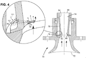
図4は、上述の燃焼器で使用する予混合装置70の例示的な構成の断面図である。図4に示した実施形態では、予混合装置70は、加圧空気を混合チャンバ74に導入するように構成された空気入口72を含む。さらに、予混合装置70は、それから燃料が、円周スロット78内に配置した収束−発散燃料噴射スロットジェット90を介して混合チャンバ74に供給される燃料プレナム76を含む。当業者には分かるように、スロット78は、予混合装置70の周辺部の周りに連続的に又は不連続的に配置することができる。図4の拡大部分は、スロット78内の収束−発散燃料噴射スロットジェット90の配置を質的に示す。燃料噴射スロットジェット90の三次元性を示すために、図4の拡大部分は、回転させている。燃料噴射スロットジェット90の更なる詳細は、図5と関連して以下にさらに説明する。
FIG. 4 is a cross-sectional view of an exemplary configuration of a
収束−発散燃料噴射スロットジェット90を介して導入された燃料は、所定の壁輪郭80上に偏向されて、燃料流82を形成する。この例示的な実施形態では、予混合装置70は、環状の構成を有し、燃料は、所定の壁輪郭80内にかつ該壁輪郭80を横切って半径方向に導入される。所定の壁輪郭80の幾何学形状及び寸法は、それに限定されないが、燃料圧力、燃料温度、流入空気の温度、及び燃料噴射速度のような因子を含む所望の予混合効率及び作動条件に基づいて選択/最適化することができる。燃料の実施例には、天然ガス、高水素ガス、水素、バイオガス、一酸化炭素及び合成ガスが含まれる。しかしながら、様々な他の燃料を使用することができる。この図示した実施形態では、所定の壁輪郭80は、コアンダ効果によって導入燃料を壁輪郭80に付着させ、従って燃料境界層を形成する。この燃料境界層は、空気の同伴を可能にし、それによって予混合装置70の混合チャンバ74内の混合効率を高める。
The fuel introduced via the convergent-divergent fuel
この図示した実施形態では、流入空気は、空気入口72を介して予混合装置70内に導入される。一部の実施形態では、空気の流れは、円周スロット78の上流又は下流に配置した複数の空気入口を通して導入して、混合チャンバ74内で空気及び燃料を混合するのを可能にすることができる。同様に、燃料は、予混合装置70の長さに沿った複数のスロットを通して複数の位置で噴射することができる。別の実施形態では、予混合装置70は、該装置70の上流に配置されて混合チャンバ74に導入した空気に旋回運動を与えるようになったスワーラ(図示せず)を含むことができる。別の実施形態では、所定の壁輪郭80を横切る燃料流に旋回運動を導入するために、スワーラ(図示せず)は、燃料入口ギャップに配置される。さらに別の実施形態では、空気スワーラは、予混合装置70からの出口平面において予混合装置70と同一の軸方向レベルかつ同軸に配置することができる。
In the illustrated embodiment, the incoming air is introduced into the
その上に、予混合装置70はまた、混合チャンバ74内に形成された燃料−空気混合気を、出口86を介して燃焼セクションに向けるための直線的な又は発散した輪郭を有するディフューザ84を含む。1つの実施形態では、ディフューザ84の角度は、約+/−0度〜約25度の範囲内にある。予混合装置70の予混合の程度は、それに限定されないが、燃料タイプ、所定の壁輪郭80の幾何学形状、空気の予旋回の程度、円周スロット78の大きさ、燃料圧力、燃料温度、流入空気の温度、ディフューザ84の長さ及び角度、並びに燃料噴射速度のような複数の因子によって制御される。
In addition, the
作動中に、所定の壁輪郭80は、ディフューザ84に沿って燃料境界層を形成し、同時に空気入口72からの空気流の一部分が燃料境界層によって同伴されて流入空気又は酸化剤と燃料との混合を促進するための剪断層を形成するのを可能にする。この図示した実施形態では、燃料は、流入空気の圧力よりも比較的高い圧力で供給される。1つの実施形態では、燃料圧力は、空気入口72における流入空気の圧力よりも約1%〜約25%大きい。
In operation, the
上述の燃料境界層は、コアンダ効果によって形成される。この図示した実施形態では、燃料流82は、壁輪郭80に付着し、かつ壁輪郭80の表面が初期の燃料流方向から離れる方向に湾曲した時でさえ、付着した状態を維持する。より具体的には、燃料流が壁輪郭80の周りで加速するにつれて、流れにわたって圧力差が存在し、この圧力差が、壁輪郭80の表面により近接するように燃料流82を偏向させる。燃料流82が壁輪郭80を横切って移動する時に、燃料流82と壁輪郭80との間に特定量の表面摩擦が発生する。流れに対するこの抵抗により、燃料流82が壁輪郭80に向かって偏向し、それによって燃料流82は壁輪郭80に近接した状態を維持する。さらに、このメカニズムによって形成された燃料境界層は、流入空気流を同伴して、空気流及び燃料の混合を促進する剪断層を形成する。さらに、本出願の出願人と同一出願人の出願番号第11/273,212号の米国特許出願には、コアンダ表面を有する予混合装置が論じられている。この特許出願の内容は、参考文献としてその全体を本明細書に組み入れている。
The fuel boundary layer described above is formed by the Coanda effect. In this illustrated embodiment, the
図5には、予混合装置70内に配置した収束−発散燃料噴射スロットジェット90の構造的特徴を示している。この収束−発散燃料噴射スロットジェット90は、酸化剤ストリーム内に噴射するのに先立ってスロット内側方に流れ剥離領域112を形成する働きをする。剥離領域112内の流れは、強制的に燃料を膨張させかつ混合乱流を形成し、それによって混合チャンバ内の酸化剤の自由ストリーム流との燃料の混合を強化する。収束−発散燃料噴射スロットジェット90は、燃料入口92、燃料出口94、上壁96、底壁98、及び側壁100を含む。燃料流の方向101に対して垂直な方向で測定した収束−発散燃料噴射スロットジェット90の高さ102は、スロットジェット90の長さ104に沿って実質的に一定であるが、側壁100は、入口92からスロート108までの収束部分106と、スロート108から下流方向に出口94まで延びる発散部分110とを形成するような側方形状にされる。
FIG. 5 shows the structural features of a convergent-divergent fuel
作動中に、燃料は、先ず収束−発散スロットジェット90の収束部分106内でスロート108に向けて加速され、次にスロットの発散部分110内での過膨張が続き、それによって出口94において酸化剤ストリーム内に噴射されるのに先立ってスロット内で側方に流れ剥離領域112が形成される。図示するように、剥離は、スロット内で発生し、強制的に燃料を膨張させかつ混合乱流を形成する。当業者には分かるように、参照符号112における流れの局所剥離によって形成された乱流レベルの増大は、収束−発散燃料噴射スロットジェット90の出口94における酸化剤の自由ストリーム流との噴射燃料の混合レベルを増大させることになる。局所剥離領域112によって生成された付加的な乱流は、燃料噴射がスロットを出る時の燃料噴射の剥離を依然として回避しながら、スロット出口94の外側の領域内での燃料及び酸化剤の混合を強化する。燃料噴射通路用の幾何学形状は、スロットジェット幾何学形状内で発生する少なくとも流体ダイナミックスにより、スロットジェットの出口から燃料及び酸化剤の混合を促進するように構成される。当業者には、スロットが収束部分106を有することが必ずしも必要ではないことが分かるであろう。収束部分106を設けた場合には、スロート領域は通常、流量を測定しかつあらゆるフラッシュバックを阻止するのを可能にするように形成され、また収束−発散スロットは、より容易に製作しかつより容易に流量損失の少ないものとすることができる。しかし一般に、スロットの入口は、幾らかの長さにわたって一定の断面とし、その後発散部分が続くようにすることができる。スロットの入口はまた、円形とすることができ、それは、実際にはスロートとして機能することになる。
In operation, fuel is first accelerated toward the
収束−発散燃料噴射スロットジェット90の発散角度αは、図5に示すように剥離領域112がスロット内に含有されるが出口94を越えては延びないようにするのに十分な大きさである。1つの実施形態では、発散角度αは、スロットジェット90の2つの側壁100の各々に対して20°又はそれより大きい。別の実施形態では、発散セクションの長さ114は、あらゆる剥離バブルがスロットジェット90の出口94の手前で洗い流されることを保証するように選択される。それに代えて、発散セクションは、スロート108からの軸方向距離につれて発散を増大させる湾曲壁を有することができる。亜音速スロットジェット90では入口92におけるよどみ点圧力対出口94における静圧の比率は、約1.2〜1.8の範囲で変化させることができる。別の実施形態では、その比率は、1.5であるのが好ましい。
The divergence angle α of the convergent-divergent fuel
図4に示すように、収束−発散燃料噴射スロットジェット90の上壁94は、燃料が、コアンダ効果を生成する表面に沿って加速する酸化剤の主ストリーム流とほぼ接線方向に噴射されるのを可能にするように、予混合装置70の壁輪郭80との間で連続面を形成する。従って、収束−発散燃料噴射スロットジェット90内の局所剥離領域112によって生成されたより高いレベルの乱流は、燃料内に導入され、従って燃料及び酸化剤の混合を高める。
As shown in FIG. 4, the
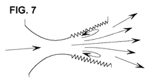
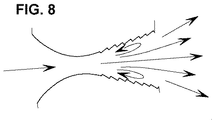
本発明の他の実施形態では、収束−発散燃料噴射スロットジェット90の側壁100は、まさに説明したように乱流の発生をさらに強化するように修正される。例えば、図6は、第1の例示的な実施形態を示し、この実施形態では、側壁100は、剥離領域112が出口94を超えて延びることになる可能性を減少させながら付加的な混合を促進するために、発散部分110に沿って粗く作られている。図7では、側壁100は、発散部分110に沿ってギザギザであり、図8では、側壁は、発散部分110に沿って階段状である。図6〜図8に示す3つの例示的な実施例に加えて、これらの表面に沿って流れ内に乱流又は小さな混乱を生成する発散部分の他の実施形態も、開示した本発明の技術的範囲内にあることは、当業者には分かるであろう。各側壁上に配置した図6〜図8に示した特徴形状、及び他の均等物は、局所断面流面積の5〜20%よりも大きい(平滑表面実施形態と比較して)遮断を構成すべきではなく、好ましくは約10%の遮断とすべきである。
In other embodiments of the invention, the
開示した予混合装置では、コアンダ表面に沿って噴射した燃料は、収束−発散燃料噴射スロットジェット90によって生成された高い乱流レベルを含み、従って、混合チャンバ内での燃料分離及び結果としての自動点火又は火炎保持の可能性を最小化及び/又は排除しながら、短い距離で酸化剤とより効率的に混合する。燃料噴射通路用の幾何学形状は、スロットジェットの出口からの燃料及び酸化剤の混合が、スロットジェット幾何学形状内で発生する流体ダイナミックスによってさらに促進されるようになっており、従って混合チャンバの噴射表面又はディフューザ壁に沿った燃料のリフトオフ又は剥離がない状態で、短い長さでの高い燃料−空気混合レベルを達成するのを助ける。開示した本発明が、予混合装置のコアンダ表面と統合することができる広範な収束−発散噴射スロットタイプを包含し、結果として、横流の形態で円形ジェットを用いる従来型の個別のジェット噴射と比較して、性能の改良をもたらすことは、当業者には分かるであろう。
In the disclosed premixing device, the fuel injected along the Coanda surface contains high turbulence levels generated by the convergent-divergent fuel
開示した本発明の別の実施形態では、予混合装置70はまた、図9に示すようにその中に複数の隣接する内部収束−発散燃料噴射スロットジェットが配置された連続燃料入口スロットを含むことができる。図9に示す収束−発散スロットの各1つはまた、まさに説明したように乱流の発生をさらに強化するような上述の側壁修正を含むことができる。複数の隣接する内部収束−発散燃料噴射スロットジェットが互いに隣接して設置されると、あらゆる2つの隣接スロットが一緒になる出口壁は、鈍頭物体後流領域を形成すべきではなく、従って剥離流、それ故火炎保持を生じる可能性がある。代わりに、この接合部は、燃料及び酸化剤が出会う前に剥離が発生することを可能にするために発散セクション内で合うようにすべきであるか、或いは接合部は、如何なる剥離領域も形成することができないような小さな半径特徴形状又は鋭いエッジを有するように形成すべきであるかのいずれかである。1つの実施形態では、鋭い接合部は、内部に、スロット出口に、又はスロット出口の後方にさえ作ることができる。
In another embodiment of the disclosed invention, the
本発明の収束−発散燃料噴射スロットジェット90は、別々の部品として形成して、予混合装置70に組立てることができる。それに代えて、スロットジェット90はまた、予混合装置70の一体形部分として形成することができる。1つの具体的な実施形態では、収束−発散燃料噴射スロットジェットは、予混合装置70の一体形部分として鋳造される。
The convergent-divergent fuel
上述の予混合装置はまた、システムの燃焼器内での反応に先だって酸素及び天然ガスを予混合するのを強化するために、気体液体化システムで使用することができる。一般的に、気体液体化システムは、空気分離ユニット、ガス処理ユニット及び燃焼器を含む。作動中に、空気分離ユニットは、空気から酸素を分離し、またガス処理ユニットは、燃焼器内での変換のための天然ガスを調製する。空気分離ユニットからの酸素及びガス処理ユニットからの天然ガスは、燃焼器に導かれ、燃焼器において、天然ガス及び酸素が、高温及び高圧で反応して合成ガスを生成する。この実施形態では、予混合装置は、燃焼器に連結されて、燃焼器内での反応に先立って酸素及び天然ガスを予混合するのを可能にする。さらに、予混合装置の少なくとも1つの表面は、所定の輪郭を有し、この所定の輪郭は、該輪郭に酸素を付着させるのを可能にするように酸素を偏向させて境界層を形成し、収束−発散スロットジェットは、混合チャンバ内での境界層流れ剥離を生じさせないで局所乱流を生成し、また境界層は、天然ガス及び酸素を高い燃料対酸素当量比(例えば、約3.5から最大約4及びそれ以上)で混合するのを可能にするように流入天然ガスを同伴して、滞留時間を最小にしながら合成ガス生産収率を最大にする。一部の実施形態では、酸素又は燃料に蒸気を加えて、プロセス効率を高めることができる。 The premixing device described above can also be used in a gas liquefaction system to enhance premixing of oxygen and natural gas prior to reaction in the combustor of the system. In general, a gas liquefaction system includes an air separation unit, a gas processing unit, and a combustor. During operation, the air separation unit separates oxygen from the air, and the gas processing unit prepares natural gas for conversion in the combustor. Oxygen from the air separation unit and natural gas from the gas processing unit are directed to a combustor where the natural gas and oxygen react at high temperatures and pressures to produce synthesis gas. In this embodiment, the premixing device is coupled to the combustor to allow premixing of oxygen and natural gas prior to reaction in the combustor. Further, at least one surface of the premixing device has a predetermined contour that deflects oxygen to allow oxygen to adhere to the contour to form a boundary layer; Convergent-divergent slot jets produce local turbulence without causing boundary layer flow separation within the mixing chamber, and the boundary layer generates natural gas and oxygen with a high fuel to oxygen equivalent ratio (eg, about 3.5 Entrained natural gas to allow mixing at a maximum of about 4 and above) to maximize synthesis gas production yield while minimizing residence time. In some embodiments, steam can be added to oxygen or fuel to increase process efficiency.
次いで合成ガスは、急冷しかつフィッシャー・トロプシュ処理ユニットに導入し、このフィッシャー・トロプシュ処理ユニットにおいて触媒作用によって水素ガス及び一酸化炭素を長鎖液体炭化水素に再結合させる。最後に、液体炭化水素は、クラッキングユニット内において製品に分留変換される。収束−発散スロットジェットと組合せたコアンダ効果に基づいて混合チャンバ内に境界層流れ剥離を生じさせないで局所乱流を生成する予混合装置は、天然ガス及び酸素の迅速な予混合並びに気体液体化システム内での実質的に短い滞留時間を生じさせる利点がある。 The synthesis gas is then quenched and introduced into a Fischer-Tropsch processing unit where hydrogen gas and carbon monoxide are recombined into long-chain liquid hydrocarbons by catalysis. Finally, liquid hydrocarbons are fractionally converted to product in the cracking unit. A premixing device that generates local turbulence without causing boundary layer flow separation in the mixing chamber based on the Coanda effect combined with a converging-diverging slot jet is a rapid natural gas and oxygen premixing and gas liquefaction system There is the advantage of producing a substantially short residence time within.
以上に説明した本方法の様々な態様は、ガスタービン及び炉などの加熱装置で使用する燃焼器のような様々な用途において実用性を有する。さらに、本明細書に記載した方法は、燃焼に先立って燃料及び空気の予混合を強化し、それによって実質的にガスタービン及び電気器具ガスバーナのようなシステムのエミッションを低減しかつ効率を高める。予混合法は、それに限定されないが、天然ガス、炭化水素、一酸化炭素、水素、バイオガス及び合成ガスを含む高い及び低い容積発熱量のガス状化石燃料のような様々な燃料に使用することができる。従って、予混合装置は、統合型ガス化複合サイクル(IGCC)の燃料フレキシブル燃焼器において、汚染物質の排出を低減するために使用することができる。加えて、予混合装置は、ガスレンジ電気器具で使用することができる。一部の実施形態では、予混合装置は、航空転用及び重作業機械用の航空機エンジン水素燃焼器及び他のガスタービン燃焼器で使用される。具体的には、記載した予混合装置は、低イギリス熱単位(BTU)から高水素及び純水素ウォッベ指数までにわたる燃料タイプを使用するシステムでのエミッションの大幅な低減を可能にすることができる。さらに、予混合装置は、特に二酸化炭素フリーサイクル及び排出ガス再循環に有用なものとなる、酸素−燃料などのストリームの部分的混合を可能にするために利用することができる。 The various aspects of the method described above have utility in various applications such as combustors for use in heating devices such as gas turbines and furnaces. Furthermore, the methods described herein enhance fuel and air premixing prior to combustion, thereby substantially reducing emissions and increasing efficiency in systems such as gas turbines and appliance gas burners. The premixing method should be used for various fuels such as high and low volumetric calorific fossil fuels including but not limited to natural gas, hydrocarbons, carbon monoxide, hydrogen, biogas and synthesis gas. Can do. Thus, the premixing device can be used to reduce pollutant emissions in an integrated gasification combined cycle (IGCC) fuel flexible combustor. In addition, the premixing device can be used with gas range appliances. In some embodiments, the premixing device is used in aircraft engine hydrogen combustors and other gas turbine combustors for aeroderivative and heavy duty machines. In particular, the described premixing device can allow for a significant reduction in emissions in systems using fuel types ranging from low British thermal units (BTU) to high hydrogen and pure hydrogen Wobbe indices. Furthermore, the premixing device can be utilized to allow partial mixing of streams such as oxy-fuel, which is particularly useful for carbon dioxide free cycles and exhaust gas recirculation.
従って、上述のコアンダ効果に基づいた予混合法は、燃焼器内の予混合及び火炎安定性を高めるのを可能にする。さらに、本方法は、エミッション、特にそのような燃焼器からのNOxエミッションの低減を可能にし、それによって環境に優しい状態でガスタービンを作動させるのを可能にする。一部の実施形態では、本方法は、燃焼器、より具体的には水素燃焼器における圧力低下を最小にするのを可能にする。加えて、コアンダ効果によって達成された予混合の強化により、ターンダウン(すなわち、バーナの最大燃焼能力対バーナの最小燃焼能力の比率)の強化、耐フラッシュバック性の強化及び燃焼器のフレームアウト・マージンの増大を可能にする。 Therefore, the premixing method based on the Coanda effect described above makes it possible to increase the premixing and flame stability in the combustor. Furthermore, the method allows for the reduction of emissions, particularly NOx emissions from such combustors, thereby enabling the gas turbine to operate in an environmentally friendly manner. In some embodiments, the method allows minimizing pressure drop in the combustor, more specifically in the hydrogen combustor. In addition, the premix enhancement achieved by the Coanda effect enhances turndown (ie, the ratio of burner maximum combustion capacity to burner minimum combustion capacity), enhanced flashback resistance, and combustor flameout. Allows an increase in margin.
これらの例示した実施形態では、燃料境界層は、コアンダ効果によって壁に沿って位置付けされて、予混合装置の出口平面を含む壁において実質的により高い燃料濃度レベルを生じる。さらに、壁におけるより高い燃料濃度の存在により、ターンダウンの利点が生じ、それによって火炎を安定させる。従って、壁に隣接して可燃性混合気が存在しないこと及び壁には100%燃料が存在することにより、その領域内には火炎が存在しないことになり、それによって耐フラッシュバック性を高める。火炎は壁から離れた状態に保たれ、従って良好なターンダウンを可能にし、かつ約0.2もの低い当量比を有する天然ガス及び空気混合気での作動を可能にすることに注目されたい。加えて、フレームアウト・マージンは、既存のシステムと比較して著しく改善される。さらに、前に記載したように、このシステムは、様々な燃料で使用することができ、従って高い燃料フレキシビリティをもたらす。例えば、本システムは、例えば燃料として天然ガス又はH2のいずれかを使用することができる。そのようなシステムの燃料フレキシビリティは、異なる燃料を必要とする異なる燃料ポートを備えたハードウェアの変更又は複雑なアーキテクチャの必要性を排除する。上述のように、記載した予混合装置は、様々な燃料で使用することができ、従ってシステムの燃料フレキシビリティをもたらす。その上、上述の方法は、既存のカン型又はカン−アニュラ型燃焼器で使用して、エミッション並びに該燃焼器内のあらゆるダイナミック振動及び変調を低減することができる。さらに、この例示した装置は、既存の燃焼器内のパイロットとして使用することができる。 In these illustrated embodiments, the fuel boundary layer is positioned along the wall by the Coanda effect, resulting in a substantially higher fuel concentration level in the wall including the exit plane of the premixer. In addition, the presence of higher fuel concentration in the wall provides the advantage of turndown, thereby stabilizing the flame. Thus, the absence of a flammable mixture adjacent to the wall and the presence of 100% fuel on the wall means that there is no flame in that region, thereby increasing flashback resistance. Note that the flame is kept away from the wall, thus allowing for good turndown and operation with natural gas and air mixtures having an equivalence ratio as low as about 0.2. In addition, the frame-out margin is significantly improved compared to existing systems. Moreover, as previously described, this system can be used with a variety of fuels, thus providing high fuel flexibility. For example, the system, either the natural gas or H 2 can be used, for example, as a fuel. The fuel flexibility of such a system eliminates the need for hardware changes or complex architectures with different fuel ports that require different fuels. As mentioned above, the described premixing device can be used with a variety of fuels, thus providing fuel flexibility of the system. Moreover, the method described above can be used with existing can-type or can-annular combustors to reduce emissions and any dynamic vibration and modulation within the combustor. Furthermore, the illustrated apparatus can be used as a pilot in an existing combustor.
燃焼システム内で燃料及び酸化剤を予混合する方法もまた、開示した本発明の実施形態の範囲内であり、そのような方法は、酸化剤入口を通して予混合装置内に酸化剤を取り込む段階と、収束−発散燃料噴射スロットジェットを通して予混合装置内に燃料を噴射する段階と、予混合装置の内壁に沿って燃料境界層を形成するように、該予混合装置内の所定の壁輪郭に向けて噴射燃料を偏向させる段階と、燃料及び酸化剤を予混合して燃料−空気混合気を形成する段階とを含み、予混合する段階は、収束−発散燃料噴射スロットジェットの発散部分内で燃料を過膨張させて該発散部分内に流れ剥離領域を形成し、該流れ剥離領域を発散部分の範囲内に限定しかつ該流れ剥離領域により、混合チャンバ内に境界層流れ剥離及び火炎保持を引き起こさずに、収束−発散燃料噴射スロットジェットの出口において混合乱流を発生して境界層からの燃料の酸化剤との混合を空気力学的に強化するように構成する段階を含む。 A method for premixing fuel and oxidant within a combustion system is also within the scope of the disclosed embodiments of the invention, such method comprising incorporating oxidant into a premixing device through an oxidant inlet. Injecting fuel into the premixing device through a convergent-divergent fuel injection slot jet and toward a predetermined wall profile in the premixing device so as to form a fuel boundary layer along the inner wall of the premixing device. Deflecting the injected fuel and premixing the fuel and oxidant to form a fuel-air mixture, wherein the premixing comprises fuel within the diverging portion of the convergent-divergent fuel injection slot jet. Overexpanding to form a flow separation region within the diverging portion, confining the flow separation region within the diverging portion, and the flow separation region triggering boundary layer flow separation and flame retention within the mixing chamber. Wake up Without the converging - comprising the step of configuring the mixing of the oxidant of the fuel from the boundary layer by generating a turbulent mixing at the outlet of the diverging fuel injection slot jet to aerodynamically enhance.
上記の説明に関して、サイズ、形態機能並びに作動、組立及び用途の状態における変更を含む本発明の部品についての最適な寸法関係は、当業者には容易に明らかかつ自明であると考えられ、従って、図面に示しかつ明細書に説明したものと均等な全ての関係は、特許請求の範囲の技術的範囲によってのみ包含されることになるように意図していることを理解されたい。加えて、本発明は、現在実用的でありかつ本発明の幾つかの例示的な実施形態であると考えられるものに関して具体的にかつ詳細に図面に示しかつ上記に十分に説明してきたが、本明細書に記載した原理及び概念から逸脱せずにそれら実施形態の多くの変更を行うことができることは、当業者には明らかであろう。従って、本発明の適切な技術的範囲は、全てのそのような変更及び均等物を包含するように特許請求の範囲を最も広く解釈することによってのみ決定されるべきである。 With regard to the above description, the optimal dimensional relationships for the parts of the present invention, including changes in size, form function and operation, assembly and application conditions, would be readily apparent and obvious to those skilled in the art, and thus It should be understood that all relationships equivalent to those shown in the drawings and described in the specification are intended to be embraced only by the scope of the claims. In addition, while the present invention has been shown in particular and in detail in the drawings and fully described above with respect to what is presently practical and considered to be several exemplary embodiments of the present invention, It will be apparent to those skilled in the art that many changes can be made in the embodiments without departing from the principles and concepts described herein. Accordingly, the proper scope of the invention should be determined only by interpreting the scope of the claims in the broadest manner so as to encompass all such modifications and equivalents.
10 ガスタービン
12 燃焼器
14 圧縮機
16 タービン
18 シャフト
20 ハウジング
22 燃焼器の例示的な構成
24 燃焼器ケーシング
26 燃焼器ライナ
28 ドームプレート
30 熱シールド
32 予混合装置
34 空気流
36 火炎
38 冷却孔
40 燃焼器
42 内側ケーシング
44 外側ケーシング
46 燃焼器ライナ
48 燃焼器ライナ
50 ドームプレート
52 熱シールド
54 熱シールド
56 ディフューザセクション
58 空気流
60 予混合装置
62 燃料パイプ
64 燃料パイプ
66 火炎
70 予混合装置
72 空気入口
74 混合チャンバ
76 燃料プレナム
78 スロット
80 壁輪郭
82 燃料流
84 ディフューザ
86 出口
90 収束−発散燃料噴射スロットジェット
92 燃料入口
94 燃料出口
96 上壁
98 底壁
100 側壁
101 流れ方向
102 スロットジェットの高さ
104 スロットジェットの長さ
106 収束部分
108 スロート
110 発散部分
112 剥離領域
DESCRIPTION OF
Claims (9)
空気入口(72)と、
該予混合装置の内壁の一部分に沿って燃料境界層を形成するように構成された壁輪郭(80)を含む複数の燃料入口スロット(78)であって、前記予混合装置(70)の周辺部の周りに配置され、前記空気入口の端部部分と流れ連通状態になった複数の燃料入口スロット(78)と、
前記空気入口及び複数の燃料入口スロットの下流に配置され、そこで該空気入口からの加圧空気が前記境界層からの燃料と混合される混合チャンバ(74)と、
その一部分内に流れ剥離領域(112)を形成するように構成され、各前記複数の燃料入口スロット内に配置された少なくとも1つの収束−発散燃料噴射スロットジェット(90)と、を含み、
前記流れ剥離領域が、前記少なくとも1つの収束−発散燃料噴射スロットジェットの発散部分(110)の範囲内に限定され、且つ、前記混合チャンバ内に境界層流れ剥離及び火炎保持を引き起こさずに、前記少なくとも1つの収束−発散燃料噴射スロットジェットの出口(94)において混合乱流を発生して前記境界層からの燃料の前記加圧空気との混合を空気力学的に強化するように構成されている、
予混合装置(70)。 A premixing device (70) comprising:
An air inlet (72);
A plurality of fuel inlet slots (78) including a wall profile (80) configured to form a fuel boundary layer along a portion of the inner wall of the premixing device, the periphery of the premixing device (70) A plurality of fuel inlet slots (78) disposed around the portion and in flow communication with an end portion of the air inlet;
A mixing chamber (74) disposed downstream of the air inlet and the plurality of fuel inlet slots, wherein pressurized air from the air inlet is mixed with fuel from the boundary layer;
At least one converging-diverging fuel injection slot jet (90) configured to form a flow separation region (112) within a portion thereof and disposed within each of the plurality of fuel inlet slots;
The flow separation region is limited to within the diverging portion (110) of the at least one converging-diverging fuel injection slot jet and without causing boundary layer flow separation and flame retention in the mixing chamber. At least one convergent-divergent fuel injection slot jet outlet (94) is configured to generate mixed turbulence to aerodynamically enhance the mixing of fuel from the boundary layer with the pressurized air. ,
Premixing device (70).
前記少なくとも1つの収束−発散燃料噴射スロットジェットが、入口(92)、スロート(108)、上壁(96)、底壁(98)及び側壁(100)を含み、
前記側壁が、前記入口から前記スロートまでの収束部分(106)と前記スロートから下流方向に前記出口まで延びる発散部分(110)とを形成するような側方形状にされ、
前記発散部分の発散角度が、20°である、
請求項1記載の予混合装置。 The wall profile is configured to deflect fuel supplied through the plurality of fuel inlet slots toward the wall profile by a Coanda effect;
The at least one converging-diverging fuel injection slot jet includes an inlet (92), a throat (108), a top wall (96), a bottom wall (98) and a side wall (100);
The side wall is shaped laterally to form a converging portion (106) from the inlet to the throat and a diverging portion (110) extending from the throat downstream to the outlet;
The divergence angle of the divergence portion is 20 ° ,
The premixing device according to claim 1.
カン型燃焼器又はカン−アニュラ型燃焼器又はアニュラ型燃焼器を含み、
燃料が、天然ガス又は高水素ガス又は水素又はバイオガス又は一酸化炭素又は合成ガスを含む、
ガスタービン燃焼器。 Including a premixing device according to any one of claims 1 to 4;
A can-type combustor or a can-annular combustor or an annular combustor,
The fuel comprises natural gas or high hydrogen gas or hydrogen or biogas or carbon monoxide or synthesis gas;
Gas turbine combustor.
酸化剤入口を通して予混合装置内に前記酸化剤を取り込む段階と、
前記予混合装置(70)の周辺部の周りに配置され、各々が少なくとも1つの収束−発散燃料噴射スロットジェットを備える複数の燃料入口スロット(78)を通して前記予混合装置内に燃料を噴射する段階と、
前記予混合装置の内壁に沿って燃料境界層を形成するように、該予混合装置内の壁輪郭に向けて前記噴射燃料を偏向させる段階と、
前記燃料及び酸化剤を予混合して燃料−空気混合気を形成する段階と、を含み、
前記予混合する段階が、前記少なくとも1つの発散燃料噴射スロットジェットの発散部分内で燃料を過膨張させて該発散部分内に流れ剥離領域を形成し、前記流れ剥離領域により、前記混合チャンバ内に境界層流れ剥離及び火炎保持を引き起こさずに、前記少なくとも1つの収束−発散燃料噴射スロットジェットの出口において混合乱流を発生して前記境界層からの燃料の前記酸化剤との混合を空気力学的に強化するように構成する段階を含む、
方法。 A method of premixing fuel and oxidant in a combustion system comprising:
Incorporating the oxidant into the premixing device through the oxidant inlet;
Injecting fuel into the premixing device through a plurality of fuel inlet slots (78) disposed around a periphery of the premixing device (70), each comprising at least one converging-diverging fuel injection slot jet. When,
Deflecting the injected fuel toward a wall profile in the premixing device to form a fuel boundary layer along the inner wall of the premixing device;
Premixing the fuel and oxidant to form a fuel-air mixture;
The premixing step causes the fuel to overexpand in the diverging portion of the at least one diverging fuel injection slot jet to form a flow separation region in the diverging portion, and the flow separation region in the mixing chamber. Mixing turbulent flow at the outlet of the at least one convergent-divergent fuel injection slot jet to cause mixing of fuel from the boundary layer with the oxidant without causing boundary layer flow separation and flame retention. Including the step of configuring to enhance,
Method.
前記壁輪郭が、前記複数の燃料入口スロットを通して供給された燃料をコアンダ効果によって該壁輪郭に向けて偏向させるように構成され、前記少なくとも1つの収束−発散燃料噴射スロットジェットが、入口(92)、スロート(108)、上壁(96)、底壁(98)及び側壁(100)を含み、前記側壁が、前記入口から前記スロートまでの収束部分(106)と前記スロートから下流方向に前記出口まで延びる発散部分(110)とを形成するような側方形状にされ、発散角度が、20°である前記発散部分により、前記境界層からの燃料の前記酸化剤との混合を空気力学的に強化するように構成する段階を達成する
ことを特徴とする請求項6記載の方法。 Step of the deflection is further seen including the step of causing the Coanda effect by the wall profile,
The wall profile is configured to deflect fuel supplied through the plurality of fuel inlet slots toward the wall profile by a Coanda effect, wherein the at least one convergent-divergent fuel injection slot jet includes an inlet (92) , A throat (108), a top wall (96), a bottom wall (98) and a side wall (100), wherein the side wall has a converging portion (106) from the inlet to the throat and the outlet in the downstream direction from the throat. The divergence portion is shaped laterally to form a divergence portion (110) extending up to and the divergence angle is 20 °, thereby aerodynamically mixing the fuel from the boundary layer with the oxidant. Achieve a stage to configure to strengthen
The method according to claim 6.
その上流に配置された請求項1〜請求項4のいずれか1項による予混合装置を含み、前記圧縮器と流れ連通状態になっており、予混合した燃料及び空気の混合気を燃焼するように構成された燃焼器と、
前記燃焼器の下流に設置され、該燃焼器から流出するガスストリームを膨張させるように構成されたタービンと、
を含むガスタービン。 A compressor;
5. A premixing device according to any one of claims 1 to 4 arranged upstream thereof, in flow communication with the compressor, so as to burn a premixed fuel / air mixture. A combustor configured to:
A turbine installed downstream of the combustor and configured to expand a gas stream exiting the combustor;
Including gas turbine.
天然ガスを調製するようになったガス処理ユニットと、
高温及び高圧で前記酸素を前記天然ガスと反応させて一酸化炭素及び水素ガスの豊富な合成ガスを生成するようになった燃焼器と、
前記燃焼器の上流に配置されて該燃焼器内での反応に先立って前記酸素及び天然ガスの予混合を可能にするようになった請求項1〜請求項4のいずれか1項による予混合装置と、
前記燃焼器と流れ連通状態になっており、前記合成ガスから仕事を取り出しかつ該合成ガスを急冷するようになったターボ膨張器と、
を含む気体液体化システム。
An air separation unit configured to separate oxygen from air;
A gas processing unit adapted to prepare natural gas;
A combustor adapted to react the oxygen with the natural gas at high temperature and pressure to produce a synthesis gas rich in carbon monoxide and hydrogen gas;
5. Premixing according to any one of the preceding claims, arranged upstream of the combustor to enable premixing of the oxygen and natural gas prior to reaction in the combustor. Equipment,
A turbo-expander that is in flow communication with the combustor, takes work from the synthesis gas, and quenches the synthesis gas;
Including gas liquefaction system.
Applications Claiming Priority (2)
| Application Number | Priority Date | Filing Date | Title |
|---|---|---|---|
| US11/558,760 US7832212B2 (en) | 2006-11-10 | 2006-11-10 | High expansion fuel injection slot jet and method for enhancing mixing in premixing devices |
| US11/558,760 | 2006-11-10 |
Publications (3)
| Publication Number | Publication Date |
|---|---|
| JP2008122065A JP2008122065A (en) | 2008-05-29 |
| JP2008122065A5 JP2008122065A5 (en) | 2010-12-16 |
| JP4831364B2 true JP4831364B2 (en) | 2011-12-07 |
Family
ID=38961175
Family Applications (1)
| Application Number | Title | Priority Date | Filing Date |
|---|---|---|---|
| JP2007287978A Expired - Fee Related JP4831364B2 (en) | 2006-11-10 | 2007-11-06 | High expansion fuel injection slot jet and method for enhancing mixing in a premixer |
Country Status (5)
| Country | Link |
|---|---|
| US (1) | US7832212B2 (en) |
| EP (1) | EP1921377A3 (en) |
| JP (1) | JP4831364B2 (en) |
| KR (1) | KR101041705B1 (en) |
| CN (1) | CN101201176B (en) |
Families Citing this family (38)
| Publication number | Priority date | Publication date | Assignee | Title |
|---|---|---|---|---|
| US8266911B2 (en) * | 2005-11-14 | 2012-09-18 | General Electric Company | Premixing device for low emission combustion process |
| KR101020596B1 (en) * | 2008-09-11 | 2011-03-09 | 서울대학교산학협력단 | Combustor and engine having the same |
| US8857733B1 (en) | 2009-01-14 | 2014-10-14 | Resodyn Corporation | Flameless thermal spray system using flame heat source |
| US9140454B2 (en) * | 2009-01-23 | 2015-09-22 | General Electric Company | Bundled multi-tube nozzle for a turbomachine |
| US8763400B2 (en) * | 2009-08-04 | 2014-07-01 | General Electric Company | Aerodynamic pylon fuel injector system for combustors |
| JP5084847B2 (en) * | 2010-01-13 | 2012-11-28 | 株式会社日立製作所 | Gas turbine combustor |
| US20110197587A1 (en) * | 2010-02-18 | 2011-08-18 | General Electric Company | Multi-tube premixing injector |
| US9435537B2 (en) * | 2010-11-30 | 2016-09-06 | General Electric Company | System and method for premixer wake and vortex filling for enhanced flame-holding resistance |
| US8863525B2 (en) | 2011-01-03 | 2014-10-21 | General Electric Company | Combustor with fuel staggering for flame holding mitigation |
| US9068750B2 (en) * | 2011-03-04 | 2015-06-30 | General Electric Company | Combustor with a pre-nozzle mixing cap assembly |
| US8899494B2 (en) | 2011-03-31 | 2014-12-02 | General Electric Company | Bi-directional fuel injection method |
| DE102011102882A1 (en) * | 2011-05-31 | 2012-12-06 | Audag Ag | Device for moistening a carrier medium, such as a paper web |
| US9127622B2 (en) | 2011-11-21 | 2015-09-08 | United Technologies Corporation | Reversible flow discharge orifice |
| US9121612B2 (en) * | 2012-03-01 | 2015-09-01 | General Electric Company | System and method for reducing combustion dynamics in a combustor |
| US9267690B2 (en) | 2012-05-29 | 2016-02-23 | General Electric Company | Turbomachine combustor nozzle including a monolithic nozzle component and method of forming the same |
| JP6028578B2 (en) * | 2013-01-15 | 2016-11-16 | 株式会社Ihi | Combustor |
| KR101320406B1 (en) * | 2013-01-17 | 2013-10-23 | 한국기계연구원 | Superlow-nox combustion apparatus using high temperature fgr and coanda effect |
| US20180231256A1 (en) * | 2017-02-10 | 2018-08-16 | General Electric Company | Rotating Detonation Combustor |
| KR101889542B1 (en) * | 2017-04-18 | 2018-08-17 | 두산중공업 주식회사 | Combustor Nozzle Assembly And Gas Turbine Having The Same |
| US10790321B2 (en) | 2017-09-29 | 2020-09-29 | Taiwan Semiconductor Manufacturing Co., Ltd. | CMOS image sensor having indented photodiode structure |
| DE102018122628B4 (en) | 2017-09-29 | 2023-08-03 | Taiwan Semiconductor Manufacturing Co., Ltd. | CMOS image sensor with jagged photodiode structure |
| US20190242582A1 (en) * | 2018-02-07 | 2019-08-08 | General Electric Company | Thermal Attenuation Structure For Detonation Combustion System |
| US10837643B2 (en) * | 2018-08-06 | 2020-11-17 | General Electric Company | Mixer assembly for a combustor |
| US11359578B2 (en) * | 2018-08-06 | 2022-06-14 | General Electric Company | Ramjet engine with rotating detonation combustion system and method for operation |
| US11073114B2 (en) * | 2018-12-12 | 2021-07-27 | General Electric Company | Fuel injector assembly for a heat engine |
| FR3089851B1 (en) * | 2018-12-12 | 2020-12-18 | Addup | Manufacturing chamber for an additive manufacturing machine |
| CN110778415B (en) * | 2019-10-29 | 2022-01-14 | 哈尔滨工业大学(威海) | Aircraft engine |
| US11828467B2 (en) * | 2019-12-31 | 2023-11-28 | General Electric Company | Fluid mixing apparatus using high- and low-pressure fluid streams |
| KR102490478B1 (en) * | 2021-02-03 | 2023-01-19 | 두산에너빌리티 주식회사 | Discharge-nozzle, Combustor and Gas turbine comprising the same |
| CN113090946B (en) * | 2021-04-06 | 2022-04-05 | 西南石油大学 | Clam type pipeline structure for promoting mixing of natural gas and hydrogen in hydrogen-doped natural gas pipeline |
| US11454396B1 (en) * | 2021-06-07 | 2022-09-27 | General Electric Company | Fuel injector and pre-mixer system for a burner array |
| US11543130B1 (en) * | 2021-06-28 | 2023-01-03 | Collins Engine Nozzles, Inc. | Passive secondary air assist nozzles |
| CN114308431B (en) * | 2021-12-20 | 2023-02-17 | 江苏大学 | Impeller reversing pulse spray head and spraying method |
| US20240010350A1 (en) * | 2022-07-08 | 2024-01-11 | Rtx Corporation | Hybrid electric hydrogen engine for aircraft |
| US11873993B1 (en) | 2023-02-02 | 2024-01-16 | Pratt & Whitney Canada Corp. | Combustor for gas turbine engine with central fuel injection ports |
| US11867392B1 (en) | 2023-02-02 | 2024-01-09 | Pratt & Whitney Canada Corp. | Combustor with tangential fuel and air flow |
| US11867400B1 (en) | 2023-02-02 | 2024-01-09 | Pratt & Whitney Canada Corp. | Combustor with fuel plenum with mixing passages having baffles |
| US11835235B1 (en) | 2023-02-02 | 2023-12-05 | Pratt & Whitney Canada Corp. | Combustor with helix air and fuel mixing passage |
Family Cites Families (18)
| Publication number | Priority date | Publication date | Assignee | Title |
|---|---|---|---|---|
| GB1495013A (en) * | 1974-06-25 | 1977-12-14 | British Petroleum Co | Coanda unit |
| JPH018834Y2 (en) * | 1984-12-28 | 1989-03-09 | ||
| US5103630A (en) * | 1989-03-24 | 1992-04-14 | General Electric Company | Dry low NOx hydrocarbon combustion apparatus |
| JPH06101841A (en) * | 1992-09-21 | 1994-04-12 | Hitachi Ltd | Air-fuel premixing structure for gas turbine combustor |
| EP0747635B1 (en) * | 1995-06-05 | 2003-01-15 | Rolls-Royce Corporation | Dry low oxides of nitrogen lean premix module for industrial gas turbine engines |
| DE69735965T2 (en) * | 1996-07-19 | 2007-01-04 | Babcock-Hitachi K.K. | burner |
| DE19729047C1 (en) * | 1997-07-08 | 1998-09-24 | Honeywell Bv | Air mixer for gas burner |
| JP3344694B2 (en) * | 1997-07-24 | 2002-11-11 | 株式会社日立製作所 | Pulverized coal combustion burner |
| DE19733767A1 (en) * | 1997-08-05 | 1999-02-11 | Dungs Karl Gmbh & Co | Fuel gas introduction device for a gas premix burner |
| JP2000039148A (en) * | 1998-07-21 | 2000-02-08 | Mitsubishi Heavy Ind Ltd | Gas turbine combustor nozzle |
| JP2000274611A (en) * | 1999-03-26 | 2000-10-03 | Hitachi Ltd | Combustor |
| JP2001280641A (en) * | 2000-03-31 | 2001-10-10 | Mitsubishi Heavy Ind Ltd | Gas turbine combustor, and method for mixing fuel and air in gas turbine combustor |
| US20020162333A1 (en) * | 2001-05-02 | 2002-11-07 | Honeywell International, Inc., Law Dept. Ab2 | Partial premix dual circuit fuel injector |
| JP2003035417A (en) * | 2001-07-24 | 2003-02-07 | Mitsubishi Heavy Ind Ltd | Pilot nozzle for gas turbine combustion device |
| US6865889B2 (en) * | 2002-02-01 | 2005-03-15 | General Electric Company | Method and apparatus to decrease combustor emissions |
| US6772595B2 (en) * | 2002-06-25 | 2004-08-10 | Power Systems Mfg., Llc | Advanced cooling configuration for a low emissions combustor venturi |
| JP2007527837A (en) * | 2004-02-20 | 2007-10-04 | サソール テクノロジー(プロプライエタリー)リミテッド | Supply of steam and hydrogen to a synthesis gas production process or synthesis gas production plant |
| DE102004030597A1 (en) * | 2004-06-24 | 2006-01-26 | Rolls-Royce Deutschland Ltd & Co Kg | Turbomachine with external wheel jet generation at the stator |
-
2006
- 2006-11-10 US US11/558,760 patent/US7832212B2/en not_active Expired - Fee Related
-
2007
- 2007-11-02 EP EP07119876.6A patent/EP1921377A3/en not_active Withdrawn
- 2007-11-06 JP JP2007287978A patent/JP4831364B2/en not_active Expired - Fee Related
- 2007-11-08 KR KR1020070113667A patent/KR101041705B1/en not_active IP Right Cessation
- 2007-11-09 CN CN2007101694452A patent/CN101201176B/en not_active Expired - Fee Related
Also Published As
| Publication number | Publication date |
|---|---|
| EP1921377A2 (en) | 2008-05-14 |
| CN101201176A (en) | 2008-06-18 |
| KR101041705B1 (en) | 2011-06-14 |
| US7832212B2 (en) | 2010-11-16 |
| EP1921377A3 (en) | 2013-12-25 |
| KR20080042714A (en) | 2008-05-15 |
| JP2008122065A (en) | 2008-05-29 |
| CN101201176B (en) | 2012-05-30 |
| US20080110173A1 (en) | 2008-05-15 |
Similar Documents
| Publication | Publication Date | Title |
|---|---|---|
| JP4831364B2 (en) | High expansion fuel injection slot jet and method for enhancing mixing in a premixer | |
| JP5331327B2 (en) | Triple ring reversal swirler | |
| JP5330693B2 (en) | Fuel flexible triple reversal swirler and method of use | |
| US20080104961A1 (en) | Method and apparatus for enhanced mixing in premixing devices | |
| US8266911B2 (en) | Premixing device for low emission combustion process | |
| US8176739B2 (en) | Coanda injection system for axially staged low emission combustors | |
| US7874157B2 (en) | Coanda pilot nozzle for low emission combustors | |
| US20100095649A1 (en) | Staged combustion systems and methods | |
| RU2686652C2 (en) | Method for operation of combustion device for gas turbine and combustion device for gas turbine | |
| JP2009052877A (en) | Gas turbine premixer with radial multistage flow path, and air-gas mixing method for gas turbine | |
| JP2010096487A (en) | Vanelet of combustor burner | |
| JP2011007479A (en) | Method and system to reduce vane swirl angle in gas turbine engine | |
| US20160265779A1 (en) | Twin radial splitter-chevron mixer with converging throat | |
| KR101774630B1 (en) | Tangential annular combustor with premixed fuel and air for use on gas turbine engines | |
| JP2009041848A (en) | Pilot mixer for mixer assembly of gas turbine engine combustor including primary fuel injector and a plurality of secondary fuel injection ports | |
| JP2014526029A (en) | Annular cylindrical combustor with graded and tangential fuel-air nozzles for use in gas turbine engines | |
| JP2014526030A (en) | Annular cylindrical combustor with premixed tangential fuel air nozzle for use in a gas turbine engine | |
| KR101832026B1 (en) | Tangential and flameless annular combustor for use on gas turbine engines |
Legal Events
| Date | Code | Title | Description |
|---|---|---|---|
| A521 | Request for written amendment filed |
Free format text: JAPANESE INTERMEDIATE CODE: A523 Effective date: 20101101 |
|
| A621 | Written request for application examination |
Free format text: JAPANESE INTERMEDIATE CODE: A621 Effective date: 20101101 |
|
| A871 | Explanation of circumstances concerning accelerated examination |
Free format text: JAPANESE INTERMEDIATE CODE: A871 Effective date: 20101101 |
|
| A975 | Report on accelerated examination |
Free format text: JAPANESE INTERMEDIATE CODE: A971005 Effective date: 20101129 |
|
| A131 | Notification of reasons for refusal |
Free format text: JAPANESE INTERMEDIATE CODE: A131 Effective date: 20101207 |
|
| A601 | Written request for extension of time |
Free format text: JAPANESE INTERMEDIATE CODE: A601 Effective date: 20110307 |
|
| RD04 | Notification of resignation of power of attorney |
Free format text: JAPANESE INTERMEDIATE CODE: A7424 Effective date: 20110307 |
|
| A602 | Written permission of extension of time |
Free format text: JAPANESE INTERMEDIATE CODE: A602 Effective date: 20110310 |
|
| A601 | Written request for extension of time |
Free format text: JAPANESE INTERMEDIATE CODE: A601 Effective date: 20110330 |
|
| A602 | Written permission of extension of time |
Free format text: JAPANESE INTERMEDIATE CODE: A602 Effective date: 20110404 |
|
| A521 | Request for written amendment filed |
Free format text: JAPANESE INTERMEDIATE CODE: A523 Effective date: 20110601 |
|
| TRDD | Decision of grant or rejection written | ||
| A01 | Written decision to grant a patent or to grant a registration (utility model) |
Free format text: JAPANESE INTERMEDIATE CODE: A01 Effective date: 20110816 |
|
| A01 | Written decision to grant a patent or to grant a registration (utility model) |
Free format text: JAPANESE INTERMEDIATE CODE: A01 |
|
| A61 | First payment of annual fees (during grant procedure) |
Free format text: JAPANESE INTERMEDIATE CODE: A61 Effective date: 20110906 |
|
| R150 | Certificate of patent or registration of utility model |
Free format text: JAPANESE INTERMEDIATE CODE: R150 |
|
| FPAY | Renewal fee payment (event date is renewal date of database) |
Free format text: PAYMENT UNTIL: 20140930 Year of fee payment: 3 |
|
| LAPS | Cancellation because of no payment of annual fees |