JP2008167669A - Lighting device - Google Patents

Lighting device Download PDF

Info

Publication number
JP2008167669A
JP2008167669A JP2007001502A JP2007001502A JP2008167669A JP 2008167669 A JP2008167669 A JP 2008167669A JP 2007001502 A JP2007001502 A JP 2007001502A JP 2007001502 A JP2007001502 A JP 2007001502A JP 2008167669 A JP2008167669 A JP 2008167669A
Authority
JP
Japan
Prior art keywords
white light
lighting device
fluorescent lamp
light source
housing
Prior art date
Legal status (The legal status is an assumption and is not a legal conclusion. Google has not performed a legal analysis and makes no representation as to the accuracy of the status listed.)
Pending
Application number
JP2007001502A
Other languages
Japanese (ja)
Inventor
Takaaki Kataoka
高明 片岡
Current Assignee (The listed assignees may be inaccurate. Google has not performed a legal analysis and makes no representation or warranty as to the accuracy of the list.)
Panasonic Electric Works Co Ltd
Original Assignee
Matsushita Electric Works Ltd
Priority date (The priority date is an assumption and is not a legal conclusion. Google has not performed a legal analysis and makes no representation as to the accuracy of the date listed.)
Filing date
Publication date
Application filed by Matsushita Electric Works Ltd filed Critical Matsushita Electric Works Ltd
Priority to JP2007001502A priority Critical patent/JP2008167669A/en
Publication of JP2008167669A publication Critical patent/JP2008167669A/en
Pending legal-status Critical Current

Links

Images

Abstract

<P>PROBLEM TO BE SOLVED: To provide a lighting device which can trap insects by single units. <P>SOLUTION: The lighting device 2A for irradiating white light irradiated from a fluorescent lamp 3, while reducing the energy in a wavelength region, having insect light-trapping effect among the white light with a filter 4, is such that by disposing a trapping portion 5 for trapping insects which fly toward the fluorescent lamp 3. Since the insects which fly toward the fluorescent lamp 3 can be trapped with the trapping portion 5, insects flying into a chamber 1 can, for example, be trapped merely with the lighting device 2A, without having to separately dispose a special device. <P>COPYRIGHT: (C)2008,JPO&INPIT

Description

本発明は、白色光を照射する照明装置に関するものである。   The present invention relates to an illumination device that emits white light.

従来、白色光を照射する照明装置としては、白色光によって虫が誘引されることを防止するために、光源から放射された白色光を、そのうち誘虫効果のある波長領域のエネルギーを例えばフィルタ等の誘虫防止手段によって低減させて照射するものが知られている。   Conventionally, as an illumination device that irradiates white light, in order to prevent insects from being attracted by white light, white light emitted from a light source is used, and energy in a wavelength region having an attracting effect is used, for example, as a filter. What is irradiated by reducing by an anti-insect means is known.

例えば、特許文献1には、そのような照明装置と誘虫装置とで構成される虫防除システムを店舗に適用することが記載されている。前記誘虫装置は、虫を誘引する光を放出し、その光で誘引されて飛翔してきた虫を捕獲するものである。
特開2004−261180号公報
For example, Patent Literature 1 describes that an insect control system including such an illumination device and an insect attracting device is applied to a store. The insect attracting device emits light that attracts insects and captures insects that have been attracted and flew by the light.
JP 2004-261180 A

ところで、前記のシステムは照明装置に誘虫装置を組み合わせることにより虫を捕獲可能にしたものであるので、照明装置だけでは例えば室内に入り込んだ虫を捕獲することができない。   By the way, since the system described above is configured to capture insects by combining a lighting device with an attracting device, for example, it is not possible to capture insects that have entered the room with the lighting device alone.

本発明は、このような事情に鑑み、単体で虫を捕獲することができる照明装置を提供することを目的とする。   In view of such circumstances, an object of the present invention is to provide an illuminating device capable of capturing insects alone.

請求項1の発明は、光源から放射された白色光を、そのうち誘虫効果のある波長領域のエネルギーを誘虫防止手段によって低減させて照射する照明装置であって、前記光源に向かって飛翔する虫を捕獲する捕獲部を備えることを特徴とするものである。   The invention of claim 1 is an illuminating device for irradiating white light emitted from a light source by reducing the energy in a wavelength region having an insecticidal effect by means of an anti-instrument prevention means, and for insects flying toward the light source. It is characterized by including a capturing section for capturing.

請求項2の発明は、請求項1に記載の照明装置において、前記誘虫防止手段は、前記白色光のうち365nm付近の波長領域のエネルギーを低減させるフィルタで構成されていることを特徴とするものである。   According to a second aspect of the present invention, in the illumination device according to the first aspect, the anti-insect means is a filter that reduces energy in a wavelength region near 365 nm of the white light. It is.

請求項3の発明は、請求項1に記載の照明装置において、前記誘虫防止手段は、前記白色光のうち410nm以下の波長領域のエネルギーを低減させるフィルタで構成されていることを特徴とするものである。   According to a third aspect of the present invention, in the illumination device according to the first aspect, the anti-insect means includes a filter that reduces energy in a wavelength region of 410 nm or less of the white light. It is.

請求項4の発明は、請求項1に記載の照明装置において、照明装置が室内に設置されたときに、光源から放射される白色光が前記室の開口に直接照射されないように当該白色光を遮光する遮光部をさらに備えることを特徴とするものである。   According to a fourth aspect of the present invention, in the lighting device according to the first aspect, when the lighting device is installed indoors, the white light emitted from the light source is not directly applied to the opening of the chamber. It further comprises a light shielding part for shielding light.

請求項5の発明は、請求項1に記載の照明装置において、前記誘虫防止手段および捕獲部は、前記光源から放射された白色光が直接入射する位置に配設されていることを特徴とするものである。   According to a fifth aspect of the present invention, in the illuminating device according to the first aspect, the insect attracting prevention means and the capturing unit are disposed at positions where white light emitted from the light source is directly incident. Is.

請求項6の発明は、請求項1に記載の照明装置において、前記捕獲部は、粘着式、電撃式、水盤式、または吸引式のものであることを特徴とするものである。   According to a sixth aspect of the present invention, in the illumination device according to the first aspect, the capturing section is of an adhesive type, an electric shock type, a basin type, or a suction type.

請求項7の発明は、請求項2または3に記載の照明装置において、前記光源は、前記フィルタで覆われていることを特徴とするものである。   A seventh aspect of the present invention is the lighting device according to the second or third aspect, wherein the light source is covered with the filter.

請求項8の発明は、請求項1に記載の照明装置において、前記光源を収容する筐体をさらに備え、前記捕獲部は、前記光源に向かって飛翔し、前記筐体内に侵入した虫を捕獲するものであることを特徴とするものである。   The invention of claim 8 is the illuminating device according to claim 1, further comprising a housing for housing the light source, wherein the capturing unit flies toward the light source and captures an insect that has entered the housing. It is what is characterized by.

請求項1の発明によれば、捕獲部によって光源に向かって飛翔する虫を捕獲することができるため、例えば室内に入り込んだ虫を別途特別な装置を設けることなく照明装置だけで捕獲することができる。   According to the invention of claim 1, since the insect flying toward the light source can be captured by the capture unit, for example, the insect that has entered the room can be captured only by the lighting device without providing a special device. it can.

ここで、虫の視覚は365nm付近の波長の光に対して最もよくなることが知られている。そこで、請求項2の発明のように、誘虫防止手段が白色光のうち365nm付近の波長領域のエネルギーを低減させるフィルタで構成されていれば、効果的に誘虫防止を図ることができる。   Here, it is known that insect vision is best for light having a wavelength around 365 nm. Therefore, as in the second aspect of the present invention, if the anti-insect means is composed of a filter that reduces the energy in the wavelength region near 365 nm of white light, the anti-insect can be effectively prevented.

あるいは、請求項3の発明のように、誘虫防止手段が白色光のうち410nm以下の波長領域のエネルギーを低減させるフィルタで構成されていれば、人間に対する白色光の色感を変えないままで、より効果的に誘虫防止を図ることができる。   Alternatively, as in the invention of claim 3, if the insect attracting prevention means is composed of a filter that reduces the energy in the wavelength region of 410 nm or less of the white light, the color sense of the white light for humans remains unchanged. Insect prevention can be achieved more effectively.

請求項4の発明によれば、遮光部によって光源から放射される白色光が室の開口に直接照射されないようになっているので、室の開口から虫が誘引されることを抑制することができる。   According to the invention of claim 4, since the white light emitted from the light source by the light shielding part is not directly irradiated to the opening of the room, it is possible to suppress the insect from being attracted from the opening of the room. .

請求項5の発明によれば、誘虫防止手段および捕獲部は、光源から放射された白色光が直接入射する位置に配設されているので、捕獲部には、誘虫効果のある波長領域のエネルギーが低減されていない状態の白色光が入射するようになる。すなわち、虫は捕獲部が見える位置に来たときは、捕獲部で反射される白色光によって捕獲部に向かって誘引されるようになり、捕獲部による虫の捕獲が効果的に行われるようになる。   According to the invention of claim 5, the attracting prevention means and the capturing part are disposed at a position where the white light emitted from the light source is directly incident, so that the capturing part has energy in a wavelength region having an attracting effect. The white light that is not reduced becomes incident. That is, when the insect comes to a position where the capture unit can be seen, the insect is attracted toward the capture unit by the white light reflected by the capture unit, so that the capture of the insect by the capture unit is performed effectively. Become.

請求項6の発明のように、捕獲部が粘着式、電撃式、水盤式、または吸引式のものであれば、薬剤を使用することなく虫を捕獲することができる。   As in the sixth aspect of the present invention, if the capturing part is of the adhesive type, the electric shock type, the basin type, or the suction type, insects can be captured without using any medicine.

請求項7の発明のように、光源が前記フィルタで覆われていれば、例えば光源を収容する筐体等に特別な構造を設けることなく誘虫防止を図ることができる。   If the light source is covered with the filter as in the seventh aspect of the invention, it is possible to prevent insects without providing a special structure, for example, in a housing for accommodating the light source.

請求項8の発明のように、捕獲部が光源に向かって飛翔し、筐体内に侵入した虫を捕獲するものであれば、捕獲部によって捕獲された虫が筐体の外から見え難くなる。   As in the eighth aspect of the present invention, if the capture unit flies toward the light source and captures the insect that has entered the housing, the insect captured by the capture unit is difficult to see from the outside of the housing.

以下、本発明を実施するための最良の形態について、図面を参照しながら詳細に説明する。   Hereinafter, the best mode for carrying out the present invention will be described in detail with reference to the drawings.

(第1実施形態)
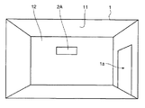
図1に示すように、本発明の第1実施形態に係る照明装置2Aは、壁面12に取り付けられて室1内に設置されるものである。なお、室1は、天井11と、窓や出入り口等の開口1aとを有している。また、本明細書では、壁面12に沿う水平方向を左右方向といい、壁面12に垂直な方向のうち壁面12から遠ざかる方向を前方、その反対方向を後方という。
(First embodiment)
As shown in FIG. 1, the lighting device 2 </ b> A according to the first embodiment of the present invention is attached to the wall surface 12 and installed in the room 1. The chamber 1 has a ceiling 11 and an opening 1a such as a window or a doorway. In this specification, the horizontal direction along the wall surface 12 is referred to as the left-right direction, and the direction away from the wall surface 12 among the directions perpendicular to the wall surface 12 is referred to as the front, and the opposite direction is referred to as the rear.

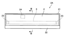
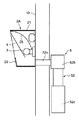
具体的には、照明装置2Aは、図2および図3に示すように、光源である蛍光ランプ3から放射された白色光を前方に照射するものであり、蛍光ランプ3と、この蛍光ランプ3を収容する筐体21とを備えている。また、筐体21内には、安定器24、反射板25、フィルタ4、および捕獲部5が配設されている。   Specifically, as shown in FIGS. 2 and 3, the illuminating device 2 </ b> A irradiates the white light emitted from the fluorescent lamp 3, which is a light source, forward. The fluorescent lamp 3 and the fluorescent lamp 3 And a housing 21 for housing the container. In addition, a ballast 24, a reflecting plate 25, a filter 4, and a capturing unit 5 are disposed in the housing 21.

蛍光ランプ3は、左右方向に延びる直管形のものである。なお、光源としては、白色光を放射するものであればよく、直管形の蛍光ランプ3以外にも例えばU字状や螺旋状等に形成された蛍光ランプを採用してもよいし、例えばキセノンランプやハロゲンランプ等の他の種類のランプを採用してもよい。また、光源の数量も適宜選定可能である。   The fluorescent lamp 3 has a straight tube shape extending in the left-right direction. As the light source, any light source may be used as long as it emits white light. In addition to the straight tube fluorescent lamp 3, for example, a fluorescent lamp formed in a U shape or a spiral shape may be employed. Other types of lamps such as xenon lamps and halogen lamps may be employed. Further, the number of light sources can be selected as appropriate.

筐体21は、横長長方形状の底壁21bと、この底壁21bの周縁部から前方に延びる長方形筒状の周壁21aとを有していて、前方に開口する箱状をなしている。なお、第1実施形態では、周壁21aの前端部に、筐体21の開口の下側部分を塞ぐように幕板22が取り付けられている。筐体21の底面である底壁21bの前面には、上下方向において中央よりも若干下寄りの位置に左右一対のソケット23が設けられており、このソケット23に蛍光ランプ3が保持されている。   The casing 21 has a horizontally long rectangular bottom wall 21b and a rectangular cylindrical peripheral wall 21a extending forward from the peripheral edge of the bottom wall 21b, and has a box shape opening forward. In the first embodiment, the curtain plate 22 is attached to the front end portion of the peripheral wall 21a so as to close the lower portion of the opening of the housing 21. A pair of left and right sockets 23 are provided on the front surface of the bottom wall 21b, which is the bottom surface of the housing 21, at positions slightly below the center in the vertical direction, and the fluorescent lamp 3 is held in the sockets 23. .

反射板25は、蛍光ランプ3の上方に配設されていて、上方に向かうに連れて徐々に大きく前方に張り出すように湾曲した形状に形成されている。このため、蛍光ランプ3から上方に放射された白色光は、反射板25で反射されて前方に向かうようになる。   The reflection plate 25 is disposed above the fluorescent lamp 3 and is formed in a curved shape so as to gradually protrude forward as it goes upward. For this reason, the white light emitted upward from the fluorescent lamp 3 is reflected by the reflecting plate 25 and goes forward.

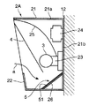
フィルタ4は、蛍光ランプ3および反射板25の前方に、上方に向かって前方に倒れるように傾斜した姿勢で配設されていて、当該フィルタ4には蛍光ランプ3から前方に放射された白色光が直接入射するとともに蛍光ランプ3から上方に放射された白色光が反射板25で反射されて入射するようになっている。このフィルタ4は、蛍光ランプ3から放射された白色光のうち誘虫効果のある波長領域のエネルギーを低減させるものであり、本発明の誘虫防止手段を構成する。具体的には、フィルタ4は、365nm付近(365nmを中心に±10nm)の波長の光をカットする透明な紫外線カットフィルタである。そして、蛍光ランプ3から前方および上方に放射された白色光は、フィルタ4を透過することによりそのうち誘虫効果のある365nm付近の波長領域のエネルギーが低減され、その後に筐体21の開口から前方に照射される。なお、フィルタ4としては、365nm以下の波長の光をカットまたは低減させるものを採用してもよい。   The filter 4 is disposed in front of the fluorescent lamp 3 and the reflecting plate 25 in an inclined posture so as to fall forward. The white light emitted forward from the fluorescent lamp 3 is applied to the filter 4. Is directly incident and white light emitted upward from the fluorescent lamp 3 is reflected by the reflecting plate 25 and incident. This filter 4 reduces the energy in the wavelength region having a worming effect in the white light emitted from the fluorescent lamp 3, and constitutes the worm-inhibiting means of the present invention. Specifically, the filter 4 is a transparent ultraviolet cut filter that cuts light having a wavelength of around 365 nm (± 10 nm centered on 365 nm). The white light radiated forward and upward from the fluorescent lamp 3 is transmitted through the filter 4 to reduce the energy in the wavelength region near 365 nm, which has an insecticidal effect, and thereafter forward from the opening of the housing 21. Irradiated. The filter 4 may be one that cuts or reduces light having a wavelength of 365 nm or less.

捕獲部5は、蛍光ランプ3に向かって飛翔し、図3中の矢印aで示すようにフィルタ4の下端部と幕板22の上端部との間に形成された隙間から筐体21内に侵入した虫を捕獲するものであり、第1実施形態では、粘着シート51で構成された粘着式のものである。すなわち、粘着シート51に接触した虫は粘着シート51に絡め取られるようになる。   The capture unit 5 flies toward the fluorescent lamp 3 and enters the housing 21 through a gap formed between the lower end portion of the filter 4 and the upper end portion of the curtain plate 22 as indicated by an arrow a in FIG. The insect which invades is captured, and in the first embodiment, an adhesive type composed of the adhesive sheet 51 is used. That is, the insect that has come into contact with the adhesive sheet 51 is entangled with the adhesive sheet 51.

粘着シート51は、筐体21の底壁21bと周壁21aの下壁部とで形成されるコーナー部分を覆うように設けられた傾斜板26の上面に貼着されることにより、蛍光ランプ3の下方に、前方に向かって先下がりに傾斜した姿勢で配設されており、当該粘着シート51には蛍光ランプ3から下方に放射された白色光が直接入射するようになっている。なお、粘着シート51は、照明装置2Aの正面からは幕板22で隠れて見えないようになっている。この粘着シート51は、紙に粘着剤を塗布したものであり、厚みが1mm以下のものである。   The adhesive sheet 51 is attached to the upper surface of the inclined plate 26 provided so as to cover the corner portion formed by the bottom wall 21b of the housing 21 and the lower wall portion of the peripheral wall 21a, whereby the fluorescent lamp 3 It is arranged in a downwardly inclined posture toward the front, and white light emitted downward from the fluorescent lamp 3 is directly incident on the adhesive sheet 51. The adhesive sheet 51 is hidden from view by the curtain 22 from the front of the lighting device 2A. This adhesive sheet 51 is obtained by applying an adhesive to paper and has a thickness of 1 mm or less.

このように構成された照明装置2Aでは、誘虫効果のある波長領域のエネルギーが低減された白色光が室1内に照射されるようになっているので、虫にとってはその光が見え難く、開口1aを通じて室1外から室1内へ虫が入り込み難くなっている。   In the illuminating device 2A configured as described above, the white light with reduced energy in the wavelength region having an insecticidal effect is irradiated into the chamber 1, so that it is difficult for the insect to see the light. It is difficult for insects to enter the room 1 from outside the room 1 through 1a.

虫が室1内に入り込んだ場合には、室1内に他の光源がなければ虫は照明装置2Aから照射される白色光に誘引されて蛍光パネル3に向かって飛翔し、筐体21内に侵入しようとするが、筐体21内には捕獲部5が配設されているので、その虫を捕獲部5によって捕獲することができる。すなわち、第1実施形態の照明装置2Aでは、室1内に入り込んだ虫を別途特別な装置を設けることなく照明装置2Aだけで捕獲することができる。   When insects enter the room 1, if there is no other light source in the room 1, the insects are attracted to the white light emitted from the lighting device 2A and fly toward the fluorescent panel 3, and the inside of the casing 21 However, since the capture unit 5 is disposed in the housing 21, the insect can be captured by the capture unit 5. That is, in the illuminating device 2A of the first embodiment, insects that have entered the chamber 1 can be captured only by the illuminating device 2A without providing a special device.

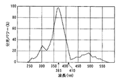
ここで、虫の視覚は、図4に示すように、365nm付近の波長の光に対して最もよくなることが知られている。そこで、第1実施形態のように、フィルタ4が蛍光ランプ3から放射された白色光のうち365nm付近の波長領域のエネルギーを低減させるものであれば、効果的に誘虫防止を図ることができる。   Here, it is known that insect vision is best for light having a wavelength near 365 nm, as shown in FIG. Therefore, as in the first embodiment, if the filter 4 reduces the energy in the wavelength region near 365 nm of the white light emitted from the fluorescent lamp 3, it is possible to effectively prevent insects.

また、捕獲部5には、当該捕獲部5が蛍光ランプ3から放射された白色光が直接入射する位置に配設されていて、誘虫効果のある波長領域のエネルギーが低減されていない状態の白色光が入射するようになっているので、虫は捕獲部5が見える位置に来たときは、捕獲部5で反射される白色光によって捕獲部5に向かって誘引されるようになり、捕獲部5による虫の捕獲が効果的に行われるようになる。   In addition, the capture unit 5 is disposed at a position where the white light emitted from the fluorescent lamp 3 directly enters the capture unit 5, and the white in a state where the energy in the wavelength region having an insecticidal effect is not reduced. Since the light is incident, when the insect comes to a position where the capture unit 5 can be seen, the insect is attracted toward the capture unit 5 by the white light reflected by the capture unit 5. The insect capture by 5 is effectively performed.

さらに、捕獲部5は粘着式のものであるので、薬剤を使用することなく虫を捕獲することができる。なお、この効果は、後述する電撃式、水盤式、または吸引式の捕獲部5でも同様である。   Furthermore, since the capture unit 5 is an adhesive type, insects can be captured without using a drug. In addition, this effect is the same also in the electric shock type | formula, basin type, or suction type capture part 5 mentioned later.

また、捕獲部5は、蛍光ランプ3に向かって飛翔し、筐体21内に侵入した虫を捕獲するものであるので、捕獲部5によって捕獲された虫が筐体21の外から見え難くなる。   Moreover, since the capture part 5 flies toward the fluorescent lamp 3 and captures insects that have entered the housing 21, the insects captured by the capture part 5 are difficult to see from the outside of the housing 21. .

なお、フィルタ4は、410nm以下の波長の光をカットするものであってもよい。この場合には、フィルタ4によって蛍光ランプ3から放射された白色光のうち410nm以下の波長領域のエネルギーが低減されるようになる。   The filter 4 may cut light with a wavelength of 410 nm or less. In this case, the energy in the wavelength region of 410 nm or less of the white light emitted from the fluorescent lamp 3 by the filter 4 is reduced.

このようにすれば、人間に対する白色光の色感を変えないままで、より効果的に誘虫防止を図ることができる。   In this way, it is possible to prevent insects more effectively without changing the color of white light to humans.

また、捕獲部5は、図5に示すように、吸引機52で構成された吸引式のものであってもよい。この吸引機52は、筐体21内の下部の空気をダクト52aを介して吸引する吸引ファン52bと、吸引ファン52bの排気口に連設された虫捕獲用の籠52cとを有している。   Further, as shown in FIG. 5, the capture unit 5 may be a suction type constituted by a suction machine 52. The suction machine 52 includes a suction fan 52b that sucks the air in the lower part of the housing 21 through the duct 52a, and an insect trapping hook 52c connected to the exhaust port of the suction fan 52b. .

このようにすれば、筐体21内に捕獲部5を配設するためのスペースを確保する必要がなくなり、照明装置としての機能やデザインを維持したまま捕獲部5を設けることができる。また、吸引式は粘着式に比べ捕獲容量が大きいことや蛍光ランプ3近傍を飛んでいる虫まで捕獲可能なため、捕獲効率が高い。   If it does in this way, it will become unnecessary to secure the space for arrange | positioning the capture part 5 in the housing | casing 21, and the capture part 5 can be provided, maintaining the function and design as an illuminating device. Further, the suction type has a higher capture efficiency than the adhesive type, and can capture even insects flying in the vicinity of the fluorescent lamp 3, so that the capture efficiency is high.

(第2実施形態)
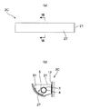
図6(a)に示すように、第2実施形態に係る照明装置2Bは、蛍光ランプ3から放射された白色光を壁面12に沿って上方に照射するものであり、筐体21が上方に開口する形状に形成されている。
(Second Embodiment)
As shown to Fig.6 (a), the illuminating device 2B which concerns on 2nd Embodiment irradiates the white light radiated | emitted from the fluorescent lamp 3 upward along the wall surface 12, and the housing | casing 21 faces upwards. It is formed in an opening shape.

筐体21内の底面から少し上側位置には、電撃格子55で構成された電撃式の捕獲部5が配設されている。そして、筐体21の底部は、電撃を受けた虫を受ける皿部となっている。   At a position slightly above the bottom surface in the housing 21, a lightning type capture unit 5 constituted by a lightning grid 55 is disposed. And the bottom part of the housing | casing 21 is a dish part which receives the insect which received the electric shock.

電撃式の捕獲部5は、メンテナンス性に優れるが、高電圧部の安全性から人の手に届き難い高所に設置するよう義務付けられている。通常、照明装置は高所に設置されるため、照明装置2Bに電撃殺虫機能を付加することは理にかなっている。   The electric shock type capture unit 5 is excellent in maintainability, but is required to be installed in a high place where it is difficult to reach human hands because of the safety of the high voltage unit. Usually, since the lighting device is installed at a high place, it makes sense to add a lightning insecticidal function to the lighting device 2B.

また、第2実施形態では、蛍光ランプ3は、筒状に配設されたフィルタ4で覆われている。なお、このフィルタ4は、365nm付近の波長の光をカットするものであっても、410nm以下の波長の光をカットするものであってもよい。   In the second embodiment, the fluorescent lamp 3 is covered with a filter 4 arranged in a cylindrical shape. The filter 4 may cut light having a wavelength near 365 nm or may cut light having a wavelength of 410 nm or less.

このような照明装置2Bであれば、蛍光ランプ3に向かって飛翔し、筐体21内に侵入した虫を電撃格子55で感電させて捕獲することができる。また、蛍光ランプ3および電撃格子55が露出していないため、デザイン性および安全性に優れたものとなる。   If it is such an illuminating device 2B, the insect which flew toward the fluorescent lamp 3 and invaded into the housing 21 can be captured by causing an electric shock with the electric shock grid 55. Further, since the fluorescent lamp 3 and the electric shock grid 55 are not exposed, the design and safety are excellent.

さらに、蛍光ランプ3がフィルタ4で覆われているので、筐体21等に特別な構造を設けることなく誘虫防止を図ることができる。また、フィルタ4を装着したまま蛍光ランプ3を交換することができる。   Furthermore, since the fluorescent lamp 3 is covered with the filter 4, it is possible to prevent insects without providing a special structure in the housing 21 or the like. Further, the fluorescent lamp 3 can be replaced with the filter 4 attached.

なお、電撃部5は、電撃式のものでなくても、図6(b)に示すように、水盤式のものであってもよい。すなわち、筐体21内の底部に水56を溜めて、当該底部を水盤として使用する。   In addition, even if the electric shock part 5 is not an electric shock type thing, as shown in FIG.6 (b), a laver type thing may be sufficient. That is, the water 56 is stored in the bottom part in the housing | casing 21, and the said bottom part is used as a basin.

このようにすれば、筐体21内の底部に溜められた水56によって虫を捕獲することができる。また、水面が蛍光ランプ3の下にあるので、蛍光ランプ3からフィルタ4を介して下方に放射された白色光は、水面で反射されて上方に照射されるようになる。そして、水面が揺らいでいれば、その揺らぎが水面で反射される反射光に反映されるため、環境デザイン的にも優れた効果を生むことが可能である。また、光が揺らぐことにより虫を刺激して活動を休止していた虫に対しても再び誘引し始めることが可能となるため、誘引性に優れたものとなる。   In this way, insects can be captured by the water 56 stored at the bottom of the housing 21. Further, since the water surface is below the fluorescent lamp 3, the white light emitted downward from the fluorescent lamp 3 through the filter 4 is reflected by the water surface and irradiated upward. If the water surface is fluctuating, the fluctuation is reflected in the reflected light reflected on the water surface, so that it is possible to produce an excellent effect in terms of environmental design. In addition, it is possible to start attracting insects that have been resting by stimulating the insects when the light fluctuates, so that the attracting property is excellent.

なお、電撃式および水盤式の捕獲部5は、第1実施形態に適用することも可能である。また、第2実施形態においても、第1実施形態で示した粘着式および吸引式の捕獲部5を適用することは可能である。   In addition, the electric shock type and basin type capture unit 5 can also be applied to the first embodiment. Also in the second embodiment, it is possible to apply the adhesive type and suction type capture unit 5 shown in the first embodiment.

(第3実施形態)
図7に示すように、第3実施形態に係る照明装置2Cは、蛍光ランプ3から放射された白色光を壁面12に沿って上方および下方に照射するものであり、筐体21が平面視で前方に開口する略コ状に形成されている。なお、第3実施形態では、第2実施形態と同様に、蛍光ランプ3がフィルタ4で覆われている。
(Third embodiment)
As shown in FIG. 7, the illumination device 2 </ b> C according to the third embodiment irradiates white light emitted from the fluorescent lamp 3 upward and downward along the wall surface 12, and the casing 21 is viewed in plan view. It is formed in a substantially U shape that opens forward. In the third embodiment, the fluorescent lamp 3 is covered with the filter 4 as in the second embodiment.

筐体21の前端部には、筐体21の前方への開口を塞ぐ遮光板27が設けられている。この遮光板27は、下方に向かうに連れて徐々に大きく後方に張り出すように湾曲した形状に形成されている。そして、この遮光板27の内側面に、粘着シート51が貼着されている。   A light shielding plate 27 that closes the front opening of the housing 21 is provided at the front end of the housing 21. The light shielding plate 27 is formed in a curved shape so as to gradually protrude rearward as it goes downward. And the adhesive sheet 51 is affixed on the inner surface of this light shielding plate 27.

このような照明装置2Cでは、厚みの薄い粘着シート51で構成される粘着式の捕獲部5を採用することがスペースの観点だけでなく捕獲に最適な蛍光ランプ3の近傍に配設できるという観点からも特に有効である。   In such an illuminating device 2 </ b> C, it is possible to arrange not only the space but also the vicinity of the fluorescent lamp 3 that is optimal for capture by adopting the adhesive-type capture unit 5 constituted by the thin adhesive sheet 51. Is particularly effective.

なお、第3実施形態においても、第1実施形態および第2実施形態で示した吸引式、電撃式、および水盤式の捕獲部5を適用することは可能である。   Also in the third embodiment, it is possible to apply the suction type, the electric shock type, and the basin type capture unit 5 shown in the first embodiment and the second embodiment.

(第4実施形態)
図8および図9に示すように、第4実施形態に係る照明装置2Dは、前方に開口する箱状の筐体21が壁面12に埋め込まれて、蛍光ランプ3から放射された白色光を天井11に向かって斜め上方に照射するものである。そして、筐体21の周壁21aのうち下壁部の上面に粘着シート51が貼着されている。なお、第4実施形態においても、第2実施形態と同様に、蛍光ランプ3がフィルタ4で覆われている。
(Fourth embodiment)
As shown in FIGS. 8 and 9, the lighting device 2 </ b> D according to the fourth embodiment has a box-shaped housing 21 that opens forward embedded in the wall surface 12 to ceiling white light emitted from the fluorescent lamp 3. 11 is irradiated obliquely upward. And the adhesive sheet 51 is affixed on the upper surface of the lower wall part among the surrounding walls 21a of the housing | casing 21. FIG. In the fourth embodiment, the fluorescent lamp 3 is covered with the filter 4 as in the second embodiment.

第4実施形態では、蛍光ランプ3は、筐体21内の下側位置に配設されているとともに、筐体21の前端部には、正面視で当該筐体21よりも一回り大きな外形の枠体28が連設されている。この枠体21の上縁部および左右の両側縁部の大きさは、筐体21の開口を塞がない程度に設定されているが、下縁部28aの大きさは、正面から蛍光ランプ3が隠れるように筐体21の開口を下側から所定の高さだけ塞ぐ程度に設定されている。このため、図9中に矢印cで示すように蛍光ランプ3から放射され、反射板25で反射された白色光は、開口1aに向かって照射されるが、図9中に矢印bで示すように開口1aからは蛍光ランプ3が直接見えなくなっている。すなわち、枠体28の下縁部28aは、蛍光ランプ3から放射される白色光が室1の開口1aに直接照射されないように当該白色光を遮光する本発明の遮光部を構成する。   In the fourth embodiment, the fluorescent lamp 3 is disposed at a lower position in the housing 21, and the front end portion of the housing 21 has an outer shape that is slightly larger than the housing 21 in a front view. A frame body 28 is provided continuously. The size of the upper edge portion and the left and right side edge portions of the frame body 21 are set so as not to block the opening of the housing 21, but the size of the lower edge portion 28a is determined from the front side. Is set so as to block the opening of the housing 21 by a predetermined height from below. Therefore, the white light emitted from the fluorescent lamp 3 and reflected by the reflecting plate 25 as shown by an arrow c in FIG. 9 is irradiated toward the opening 1a, but as shown by an arrow b in FIG. In addition, the fluorescent lamp 3 is not directly visible from the opening 1a. That is, the lower edge portion 28a of the frame body 28 constitutes a light shielding portion of the present invention that shields white light emitted from the fluorescent lamp 3 so that the white light emitted from the fluorescent lamp 3 is not directly irradiated onto the opening 1a of the chamber 1.

このようにすれば、蛍光ランプ3から放射される白色光が室1の開口1aに直接照射されないので、室1の開口1aから虫が誘引されることを抑制することができる。   In this way, white light emitted from the fluorescent lamp 3 is not directly applied to the opening 1 a of the chamber 1, so that it is possible to suppress the insects from being attracted from the opening 1 a of the chamber 1.

なお、第4実施形態においても、第1実施形態および第2実施形態で示した吸引式、電撃式、および水盤式の捕獲部5を適用することは可能である。   Also in the fourth embodiment, it is possible to apply the suction type, electric shock type, and basin type capture units 5 shown in the first embodiment and the second embodiment.

(第5実施形態)
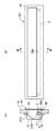
図10に示すように、第5実施形態に係る照明装置2Eは、天井11における開口1aが設けられた壁面12の近傍の位置に、下方に開口する箱状の筐体21が埋め込まれて、蛍光ランプ3から放射された白色光を下方に照射するものである。そして、筐体21の周壁21aのうち前壁部に吸引式の捕獲部5が設けられている。なお、第5実施形態においても、第2実施形態と同様に、蛍光ランプ3がフィルタ4で覆われている。
(Fifth embodiment)
As shown in FIG. 10, in the lighting device 2E according to the fifth embodiment, a box-shaped housing 21 that opens downward is embedded at a position in the vicinity of the wall surface 12 provided with the opening 1a in the ceiling 11, The white light emitted from the fluorescent lamp 3 is irradiated downward. And the suction-type capture part 5 is provided in the front wall part among the surrounding walls 21a of the housing | casing 21. FIG. In the fifth embodiment, the fluorescent lamp 3 is covered with the filter 4 as in the second embodiment.

第5実施形態では、蛍光ランプ3は、筐体21内の後側位置に配設されているとともに、筐体21の周壁21aのうち後壁部の下端部には、内側に突出する遮光板(本発明の遮光部に相当)29Aが設けられている。そして、遮光板29Aによって、蛍光ランプ3から放射される白色光が室1の開口1aに直接照射されないように遮光されるようになっている。   In the fifth embodiment, the fluorescent lamp 3 is disposed at the rear side position in the housing 21, and a light shielding plate that protrudes inwardly at the lower end portion of the rear wall portion of the peripheral wall 21 a of the housing 21. 29A (corresponding to the light shielding portion of the present invention) is provided. The white light emitted from the fluorescent lamp 3 is shielded by the light shielding plate 29A so that it is not directly irradiated onto the opening 1a of the chamber 1.

このようにしても、第4実施形態と同様の効果を得ることができる。   Even if it does in this way, the effect similar to 4th Embodiment can be acquired.

なお、図11に示すように、筐体21内に、2本の蛍光ランプ3が前後に並んで配設される場合には、筐体21内の下側位置に、前後方向に複数枚のルーバー29Bを並設して、これらのルーバー29Bで本発明の遮光部を構成してもよい。   As shown in FIG. 11, when two fluorescent lamps 3 are arranged in the front and rear in the housing 21, a plurality of sheets in the front and rear direction are provided at the lower position in the housing 21. The louvers 29B may be arranged side by side, and the light shielding portion of the present invention may be configured by these louvers 29B.

また、第5実施形態においても、第1実施形態および第2実施形態で示した粘着式および電撃式の捕獲部5を適用することは可能である。   Also in the fifth embodiment, it is possible to apply the adhesive type and electric shock type capturing units 5 shown in the first and second embodiments.

本発明の第1実施形態に係る照明装置が室内に設置された状態を示す配置図である。It is a layout view showing a state in which the lighting device according to the first embodiment of the present invention is installed indoors. 第1実施形態の照明装置の正面図である。It is a front view of the illuminating device of 1st Embodiment. 図2のIII−III線断面図である。It is the III-III sectional view taken on the line of FIG. 虫の視覚特性を示すグラフである。It is a graph which shows the visual characteristic of an insect. 第1実施形態の照明装置の変形例の図3に対応する図である。It is a figure corresponding to FIG. 3 of the modification of the illuminating device of 1st Embodiment. (a)は第2実施形態に係る照明装置の概略構成図、(b)はその変形例の概略構成図である。(A) is a schematic block diagram of the illuminating device which concerns on 2nd Embodiment, (b) is a schematic block diagram of the modification. (a)は第3実施形態に係る照明装置の正面図、(b)は(a)のVII−VII線断面図である。(A) is a front view of the illuminating device which concerns on 3rd Embodiment, (b) is the VII-VII sectional view taken on the line of (a). (a)は第4実施形態に係る照明装置の正面図、(b)は(a)のVIII−VIII線断面図である。(A) is a front view of the illuminating device which concerns on 4th Embodiment, (b) is the VIII-VIII sectional view taken on the line of (a). 第4実施形態の照明装置が室内に設置された状態を示す配置図である。It is a layout view showing a state where the lighting device of the fourth embodiment is installed indoors. (a)は第5実施形態に係る照明装置の概略構成図、(b)は第5実施形態の照明装置が室内に設置された状態を示す配置図である。(A) is a schematic block diagram of the illuminating device which concerns on 5th Embodiment, (b) is a layout which shows the state by which the illuminating device of 5th Embodiment was installed indoors. 第5実施形態の照明装置の変形例の概略構成図である。It is a schematic block diagram of the modification of the illuminating device of 5th Embodiment.

符号の説明Explanation of symbols

1 室
12 壁面
11 天井
1a 開口
2A〜2E 照明装置
21 筐体
28a 下縁部(遮光部)
29A 遮光板(遮光部)
29B ルーバー(遮光部)
3 蛍光ランプ(光源)
4 フィルタ(誘虫防止手段)
5 捕獲部
51 粘着シート
52 吸引機
55 電撃格子
56 水
1 room 12 wall surface 11 ceiling 1a opening 2A-2E illuminating device 21 housing 28a lower edge part (light-shielding part)
29A Shading plate (shading part)
29B Louver (shading part)
3 Fluorescent lamp (light source)
4 filters (insect prevention measures)
5 Capturing part 51 Adhesive sheet 52 Suction machine 55 Lightning grid 56 Water

Claims (8)

光源から放射された白色光を、そのうち誘虫効果のある波長領域のエネルギーを誘虫防止手段によって低減させて照射する照明装置であって、
前記光源に向かって飛翔する虫を捕獲する捕獲部を備えることを特徴とする照明装置。
An illumination device that irradiates white light emitted from a light source by reducing the energy in a wavelength region having an insecticidal effect by means of preventing insects,
An illuminating device comprising: a capturing unit that captures insects flying toward the light source.
前記誘虫防止手段は、前記白色光のうち365nm付近の波長領域のエネルギーを低減させるフィルタで構成されていることを特徴とする請求項1に記載の照明装置。   The lighting device according to claim 1, wherein the insect attracting prevention unit is configured by a filter that reduces energy in a wavelength region near 365 nm of the white light. 前記誘虫防止手段は、前記白色光のうち410nm以下の波長領域のエネルギーを低減させるフィルタで構成されていることを特徴とする請求項1に記載の照明装置。   The lighting device according to claim 1, wherein the insect attracting prevention unit is configured by a filter that reduces energy in a wavelength region of 410 nm or less in the white light. 照明装置が室内に設置されたときに、光源から放射される白色光が前記室の開口に直接照射されないように当該白色光を遮光する遮光部をさらに備えることを特徴とする請求項1に記載の照明装置。   The light-shielding part which shields the said white light so that the white light radiated | emitted from a light source may not be directly irradiated to the opening of the said room when an illuminating device is installed indoors, It is characterized by the above-mentioned. Lighting equipment. 前記誘虫防止手段および捕獲部は、前記光源から放射された白色光が直接入射する位置に配設されていることを特徴とする請求項1に記載の照明装置。   The lighting device according to claim 1, wherein the insect attracting prevention unit and the capturing unit are disposed at a position where white light emitted from the light source is directly incident. 前記捕獲部は、粘着式、電撃式、水盤式、または吸引式のものであることを特徴とする請求項1に記載の照明装置。   The lighting device according to claim 1, wherein the capturing unit is of an adhesive type, an electric shock type, a basin type, or a suction type. 前記光源は、前記フィルタで覆われていることを特徴とする請求項2または3に記載の照明装置。   The lighting device according to claim 2, wherein the light source is covered with the filter. 前記光源を収容する筐体をさらに備え、前記捕獲部は、前記光源に向かって飛翔し、前記筐体内に侵入した虫を捕獲するものであることを特徴とする請求項1に記載の照明装置。   The lighting device according to claim 1, further comprising: a housing that houses the light source, wherein the capturing unit captures insects that fly toward the light source and enter the housing. .
JP2007001502A 2007-01-09 2007-01-09 Lighting device Pending JP2008167669A (en)

Priority Applications (1)

Application Number Priority Date Filing Date Title
JP2007001502A JP2008167669A (en) 2007-01-09 2007-01-09 Lighting device

Applications Claiming Priority (1)

Application Number Priority Date Filing Date Title
JP2007001502A JP2008167669A (en) 2007-01-09 2007-01-09 Lighting device

Publications (1)

Publication Number Publication Date
JP2008167669A true JP2008167669A (en) 2008-07-24

Family

ID=39696352

Family Applications (1)

Application Number Title Priority Date Filing Date
JP2007001502A Pending JP2008167669A (en) 2007-01-09 2007-01-09 Lighting device

Country Status (1)

Country Link
JP (1) JP2008167669A (en)

Cited By (5)

* Cited by examiner, † Cited by third party
Publication number Priority date Publication date Assignee Title
JP2010029093A (en) * 2008-07-28 2010-02-12 Panasonic Electric Works Co Ltd Insect catcher
KR101063383B1 (en) * 2008-10-29 2011-09-07 현대자동차주식회사 Rear combination lamp with worm attractor
US20120317869A1 (en) * 2011-06-15 2012-12-20 Ecolab Usa Inc. Flying insect attraction station
JP2019036389A (en) * 2017-08-10 2019-03-07 パナソニックIpマネジメント株式会社 Lighting apparatus
CN112664884A (en) * 2021-01-22 2021-04-16 张志峰 Automatic deinsectization LED street lamp is used in garden

Cited By (7)

* Cited by examiner, † Cited by third party
Publication number Priority date Publication date Assignee Title
JP2010029093A (en) * 2008-07-28 2010-02-12 Panasonic Electric Works Co Ltd Insect catcher
KR101063383B1 (en) * 2008-10-29 2011-09-07 현대자동차주식회사 Rear combination lamp with worm attractor
US20120317869A1 (en) * 2011-06-15 2012-12-20 Ecolab Usa Inc. Flying insect attraction station
US10292379B2 (en) * 2011-06-15 2019-05-21 Ecolab Usa Inc. Flying insect attraction station
JP2019036389A (en) * 2017-08-10 2019-03-07 パナソニックIpマネジメント株式会社 Lighting apparatus
CN112664884A (en) * 2021-01-22 2021-04-16 张志峰 Automatic deinsectization LED street lamp is used in garden
CN112664884B (en) * 2021-01-22 2023-04-07 深圳市绿睿生物环保科技有限公司 Automatic deinsectization LED street lamp is used in garden

Similar Documents

Publication Publication Date Title
KR102526536B1 (en) Adhesive type insect trap
JP4506503B2 (en) Capture insecticidal equipment
JP4640333B2 (en) Insect trap
JP4702158B2 (en) Pest control device and its mounting structure
JP2021500076A (en) How to attract catchers and flying insects to insect catchers
JP4770626B2 (en) Insect trapping device
JP2008167669A (en) Lighting device
KR20220002446A (en) insect trap
JP2007289122A (en) Insect catcher
ITTO970273A1 (en) TRAP FOR FLIES WITH TWO OR MORE DIAGRAMS OF DIRECTIONAL LIGHT.
JP2008061561A (en) Insect-trapping and insecticidal apparatus
JP4706633B2 (en) Pest control equipment
JP2008118865A (en) Device for capturing insects
JP2007037429A (en) Insect trap
KR200481159Y1 (en) Wall Tapestry Type Air Cleaner
JP4640332B2 (en) Insect trap
JP2005058050A (en) Insect-trapping and killing apparatus
JP4934435B2 (en) Insect device and system
KR20100007493A (en) Apparatus for capturing vermin
JP2000287600A (en) Insect-catching and collecting device
JP2008136393A (en) Pressure-sensitive adhesive type apparatus for capturing insect
JP3968717B2 (en) lighting equipment
US20070236945A1 (en) Projector
JP2008154517A (en) Pest control structure
JP2005058174A (en) Insect-trapping and killing apparatus