JP2008166375A - Plug-in unit and electronic equipment - Google Patents
Plug-in unit and electronic equipment Download PDFInfo
- Publication number
- JP2008166375A JP2008166375A JP2006352088A JP2006352088A JP2008166375A JP 2008166375 A JP2008166375 A JP 2008166375A JP 2006352088 A JP2006352088 A JP 2006352088A JP 2006352088 A JP2006352088 A JP 2006352088A JP 2008166375 A JP2008166375 A JP 2008166375A
- Authority
- JP
- Japan
- Prior art keywords
- plug
- unit
- air
- air volume
- electronic device
- Prior art date
- Legal status (The legal status is an assumption and is not a legal conclusion. Google has not performed a legal analysis and makes no representation as to the accuracy of the status listed.)
- Pending
Links
- 238000001816 cooling Methods 0.000 claims abstract description 30
- 230000020169 heat generation Effects 0.000 claims description 10
- 239000002184 metal Substances 0.000 abstract description 2
- 238000009423 ventilation Methods 0.000 description 6
- 230000000694 effects Effects 0.000 description 1
Images
Classifications
-
- H—ELECTRICITY
- H05—ELECTRIC TECHNIQUES NOT OTHERWISE PROVIDED FOR
- H05K—PRINTED CIRCUITS; CASINGS OR CONSTRUCTIONAL DETAILS OF ELECTRIC APPARATUS; MANUFACTURE OF ASSEMBLAGES OF ELECTRICAL COMPONENTS
- H05K7/00—Constructional details common to different types of electric apparatus
- H05K7/20—Modifications to facilitate cooling, ventilating, or heating
- H05K7/20536—Modifications to facilitate cooling, ventilating, or heating for racks or cabinets of standardised dimensions, e.g. electronic racks for aircraft or telecommunication equipment
- H05K7/20554—Forced ventilation of a gaseous coolant
- H05K7/20563—Forced ventilation of a gaseous coolant within sub-racks for removing heat from electronic boards
-
- H—ELECTRICITY
- H05—ELECTRIC TECHNIQUES NOT OTHERWISE PROVIDED FOR
- H05K—PRINTED CIRCUITS; CASINGS OR CONSTRUCTIONAL DETAILS OF ELECTRIC APPARATUS; MANUFACTURE OF ASSEMBLAGES OF ELECTRICAL COMPONENTS
- H05K7/00—Constructional details common to different types of electric apparatus
- H05K7/20—Modifications to facilitate cooling, ventilating, or heating
Landscapes
- Engineering & Computer Science (AREA)
- Physics & Mathematics (AREA)
- Thermal Sciences (AREA)
- Microelectronics & Electronic Packaging (AREA)
- Aviation & Aerospace Engineering (AREA)
- Cooling Or The Like Of Electrical Apparatus (AREA)
Abstract
Description
本発明は、電子デバイスを備えたプラグインユニット及びバックプラグイン構造で複数の実装スロットを備えた電子機器に関し、特に、発熱量や通風抵抗が異なるプラグインユニットに換装しても、機器本体の筐体構造を変更することなく適切な風量分布に調整できる電子機器に関する。 The present invention relates to a plug-in unit including an electronic device and an electronic device including a plurality of mounting slots in a back plug-in structure, and in particular, even if the device is replaced with a plug-in unit having a different amount of heat generation or ventilation resistance, The present invention relates to an electronic device that can be adjusted to an appropriate air volume distribution without changing the housing structure.
プラグインユニットの発熱を冷却ファンによって強制空冷する電子機器において、ファンの騒音や動力の最適化を図るため風量に制限が生じる場合、その電子機器の風量は各プラグインユニットの発熱量や流路の通風抵抗に対応して最適な風量分布となるように調整される。 In an electronic device in which the heat generated by a plug-in unit is forcibly air-cooled by a cooling fan, if the air volume is limited in order to optimize the noise and power of the fan, the air volume of the electronic device depends on the heat generation amount and flow path of each plug-in unit. It is adjusted so as to obtain an optimum air volume distribution corresponding to the ventilation resistance.
風量を調整する構造は、特許文献1や特許文献2に開示されているように、プラグインユニットの吸気口あるいは排気口に当たる部分に風量調整プレートを配置する構造が用いられる。
As the structure for adjusting the air volume, as disclosed in Patent Document 1 and
風量調整プレートは、各プラグインユニットに対応して開口率の異なる多孔板を有する構造であり、筐体側に取り付けられて固定される。 The air volume adjusting plate has a structure having a perforated plate having a different opening ratio corresponding to each plug-in unit, and is attached to the housing side and fixed.
従来の風量調整機能付き電子機器は、風量調整プレートを筐体に固定する構造であるため、実装互換性があっても発熱量や通風抵抗が異なるプラグインユニットへ換装した場合に、風量調整プレートの開口率を変えられないため、風量分布が適切でなくなる場合がある。 Conventional electronic devices with airflow adjustment function have a structure in which the airflow adjustment plate is fixed to the housing. Therefore, if the airflow adjustment plate is replaced with a plug-in unit that has different heat generation and ventilation resistance even if there is mounting compatibility, the airflow adjustment plate Since the aperture ratio cannot be changed, the air volume distribution may not be appropriate.
また、特許文献3には、機器を収容するラックに開口率を調整可能な開口を設けたラック冷却構造が開示されている。
しかし、バックプラグイン構造の電子機器においてこのような構成を採用すると、ラック内の開口の開口率を調整する作業を行いにくい。特に、機器が薄く、奥行きがある場合には、開口率の調整のために隣接するプラグインユニットを取り外して作業をしなければならなくなり、風量分布を調整するための作業性が低くなってしまう。
However, when such a configuration is employed in an electronic device having a back plug-in structure, it is difficult to perform an operation of adjusting the aperture ratio of the opening in the rack. In particular, when the equipment is thin and deep, the work must be done by removing the adjacent plug-in unit to adjust the aperture ratio, and the workability for adjusting the air volume distribution becomes low. .
特許文献4には筐体に形成された給気口にシャッタ板を設置し、収容したプリントユニットの温度が所定温度を超えた場合に給気口を開放して外気を取り込むプリンタが開示されている。特許文献4において、吸気口の開口率はプリントユニットの温度に応じて多段階に制御される。
しかし、特許文献4のような構成では、プリントユニットの温度を検出するためのセンサ類や、検出した温度に応じてシャッタ板を駆動させるための機構が不可欠となる。
However, in the configuration as disclosed in
プリンタと異なり一般な電子機器では、各プラグインユニットの発熱量はそれぞれほぼ所定値であり、駆動中に発熱量が変化することはほとんどない。このため、特許文献4のようなセンサ類やシャッタの駆動機構を設けたとしても、装置の大型化や複雑化を招くだけで風量分布の調整には有効ではない。
Unlike a printer, in a general electronic device, the heat generation amount of each plug-in unit is almost a predetermined value, and the heat generation amount hardly changes during driving. For this reason, even if the sensors and the shutter driving mechanism as in
本発明はかかる問題に鑑みてなされたものであり、電子機器に実装された際に出入りする冷却風の風量を調整可能なプラグインユニット、及び、発熱量や通風抵抗が異なるプラグインユニットへ換装した場合でも、装置内の風量分布を適切に変更できる電子機器を提供することを目的とする。 The present invention has been made in view of such a problem, and is replaced with a plug-in unit capable of adjusting the amount of cooling air flowing in and out when mounted on an electronic device, and a plug-in unit having different heat generation amount and ventilation resistance. It is an object of the present invention to provide an electronic device that can appropriately change the air volume distribution in the apparatus.
上記目的を達成するため、本発明は、第1の態様として、冷却ファンを備えた電子機器筐体内に収容されて用いられるプラグインユニットであって、電子機器筐体内に収容された場合に冷却ファンが発生させる冷却風の入口及び出口となる部分の少なくとも一方に、開口率が可変の開口を備えた風量調整部材を設置したことを特徴とするプラグインユニットを提供するものである。 In order to achieve the above object, according to a first aspect of the present invention, there is provided a plug-in unit that is housed and used in an electronic device casing provided with a cooling fan, and is cooled when accommodated in the electronic device casing. It is an object of the present invention to provide a plug-in unit characterized in that an air volume adjusting member having an opening with a variable opening ratio is installed in at least one of the inlet and outlet of cooling air generated by a fan.
本発明の第1の態様においては、風量調整部材の開口率は、実装された電子デバイスの発熱量に応じた範囲で可変であることが好ましい。 In the first aspect of the present invention, it is preferable that the aperture ratio of the air volume adjusting member is variable in a range corresponding to the heat generation amount of the mounted electronic device.
本発明の第1の態様の上記のいずれの構成においても、風量調整部材は、開口の近傍に設置されたスライド部材を摺動させることにより開口率を調整可能であることが好ましい。又は、風量調整部材は、開口を閉塞する蓋を着脱することにより開口率を調整可能であることが好ましい。 In any of the above configurations of the first aspect of the present invention, it is preferable that the air flow rate adjusting member can adjust the aperture ratio by sliding a slide member installed in the vicinity of the opening. Or it is preferable that an air flow rate adjustment member can adjust an aperture ratio by removing the lid | cover which obstruct | occludes opening.
また、上記目的を達成するため、本発明は、第2の態様として、上記本発明の第1の態様のいずれか構成にかかるプラグインユニットを筐体内に収容するための実装スロットを複数備えた電子機器を提供するものである。 In order to achieve the above object, the present invention includes, as a second aspect, a plurality of mounting slots for housing the plug-in unit according to any configuration of the first aspect of the present invention in the housing. Electronic equipment is provided.
本発明の第2の態様においては、冷却ファンは、実装スロットに実装されたプラグインユニットから強制的に空気を吸い出すことによって冷却風を発生させることが好ましい。又は、冷却ファンは、実装スロットに実装されたプラグインユニットへ強制的に空気を送り込むことによって冷却風を発生させることが好ましい。 In the second aspect of the present invention, it is preferable that the cooling fan generate cooling air by forcibly sucking air from the plug-in unit mounted in the mounting slot. Alternatively, the cooling fan preferably generates cooling air by forcibly sending air to the plug-in unit mounted in the mounting slot.
本発明によれば、電子機器に実装された際に出入りする冷却風の風量を調整可能なプラグインユニット、及び、発熱量や通風抵抗が異なるプラグインユニットへ換装した場合でも、装置内の風量分布を適切に変更できる電子機器を提供できる。 According to the present invention, the amount of air in the apparatus can be adjusted even when the plug-in unit is capable of adjusting the amount of cooling air that comes in and out when mounted on an electronic device, and the plug-in unit has a different calorific value or ventilation resistance. An electronic device capable of appropriately changing the distribution can be provided.
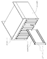
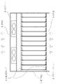
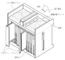
本発明の好適な実施の形態について説明する。図1及び図2に、本実施形態にかかる電子機器の構成を示す。電子機器1は、バックプラグイン構造で複数のプラグインユニット3が実装される。また、電子機器1は、プラグインユニット3の発熱を強制冷却するための冷却ファン2を有する。さらに、装置の下部に吸気部5を、上部に排気部6を有する。
A preferred embodiment of the present invention will be described. 1 and 2 show the configuration of the electronic apparatus according to the present embodiment. The electronic device 1 is mounted with a plurality of plug-in
冷却ファン2は、排気温度を検知して回転数を制御し風量を調整可能である。
各プラグインユニット3には、それぞれ開口率の異なる多孔板である風量調整金具4が設けられている。
The
Each plug-in
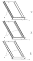
図3に、プラグインユニット3の構成を示す。プラグインユニット3の風量調整金具4は開口率が可変の構造となっている。開口率を可変とする構造は、開口にスライド式の板を設置して孔の開口率を可変とする構造や、開口に取り外し可能な蓋を設置する構造などが適用可能である。なお、風量調整金具4の開口率を可変とする構造は、上記の例に限定されず、他の構成を適用することも可能である。
FIG. 3 shows the configuration of the plug-in
発熱量が小さいプラグインユニット3aは、風量調整金具4aのように開口率を低いレベルで調整が可能である。発熱量が大きいプラグインユニット3bは、風量調整金具4bのように開口率を高いレベルで調整可能である。発熱量が微小なプラグインユニット3cは、風量調整金具4cのように、開口を閉じることが可能である。 The plug-in unit 3a having a small calorific value can adjust the aperture ratio at a low level like the air volume adjusting bracket 4a. The plug-in unit 3b that generates a large amount of heat can adjust the aperture ratio at a high level like the air volume adjusting bracket 4b. The plug-in unit 3c with a small calorific value can close the opening like the air volume adjustment fitting 4c.
風量調整金具4の開口率を低くすると、他のプラグインユニット3へ供給される冷却風の風量が増大する。逆に、風量調整金具4の開口率を高くすると他のプラグインユニット3へ供給される冷却風の風量が減少する。よって、各プラグインユニットの風量調整金具4の開口率を調整することにより、各プラグインユニット3へ供給される冷却風を任意の割合で分配することが可能となる。
When the opening ratio of the air volume adjusting
さらに、発熱量が異なるプラグインユニット3へ換装した場合でも、交換後のプラグインユニットには発熱量に応じた風量調整金具4が装着されているため、そのプラグインユニット3に適した開口率に調整可能である。
Further, even when the plug-in
このような開口率の調整は、プラグインユニット3を電子機器1から取り出した状態で行えるため、作業性に優れる。
Since the adjustment of the aperture ratio can be performed in a state where the plug-in
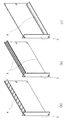
図4に、プラグインユニット3の別の構成例を示す。図示するのは、風量調整金具4が一つのみの構成である。風量調整金具4を一つだけとした場合でも図3に示した構造と同様の機能を奏することはいうまでもない。
FIG. 4 shows another configuration example of the plug-in
各プラグインユニットの風量分布を調整することにより、各プラグインユニットの排気温度を均一にできる。
排気温度にバラツキがある場合は、最も高温となるプラグインユニットのデバイス寿命が装置寿命となる。しかし、排気温度を均一化できれば、最も高温であったプラグインユニットの排気温度を限界まで下げることができ、デバイスの寿命を延ばすことができる。
By adjusting the air volume distribution of each plug-in unit, the exhaust temperature of each plug-in unit can be made uniform.
When the exhaust temperature varies, the device life of the plug-in unit that is the highest temperature is the device life. However, if the exhaust temperature can be made uniform, the exhaust temperature of the plug-in unit, which is the highest temperature, can be lowered to the limit, and the lifetime of the device can be extended.
このように、本実施形態にかかる電子機器は、発熱量や通風抵抗の異なるプラグインユニットに交換する場合でも、筐体の構造を変更することなく適切な風量分布に調整できる。 As described above, the electronic apparatus according to the present embodiment can be adjusted to an appropriate air volume distribution without changing the structure of the housing even when the electronic apparatus is replaced with a plug-in unit having a different calorific value or ventilation resistance.
また、風量分布は、プラグインユニット側の構造(風量調整金具)によって調整できるため、プラグインユニットの構成や種類に関わらず電子機器の筐体を共通とでき、コストを低減できる。 In addition, since the air volume distribution can be adjusted by the structure on the plug-in unit side (air volume adjusting bracket), the housing of the electronic device can be made common regardless of the configuration and type of the plug-in unit, and the cost can be reduced.
なお、上記実施形態は本発明の好適な実施の一例であり、本発明はこれに限定されることはない。
例えば、上記実施形態においては排気側に冷却ファンを備え、筐体内の空気を強制的に吸い出す構成を例としたが、吸気側に冷却ファンを設けて筐体内に空気を強制的に送り込む構成であっても同様の効果が得られる。
このように、本発明は様々な変形が可能である。
In addition, the said embodiment is an example of suitable implementation of this invention, and this invention is not limited to this.
For example, in the above embodiment, the cooling fan is provided on the exhaust side and the air in the housing is forcibly sucked out. However, the cooling fan is provided on the intake side and the air is forcibly sent into the housing. Even if it exists, the same effect is acquired.
As described above, the present invention can be variously modified.
1 電子機器
2 冷却ファン
3 プラグインユニット
4 風量調整金具
5 吸気部
6 排気部
DESCRIPTION OF SYMBOLS 1
Claims (7)
前記電子機器筐体内に収容された場合に前記冷却ファンが発生させる冷却風の入口及び出口となる部分の少なくとも一方に、開口率が可変の開口を備えた風量調整部材を設置したことを特徴とするプラグインユニット。 A plug-in unit used by being housed in an electronic device housing having a cooling fan,
An air volume adjusting member having an opening with a variable opening ratio is installed in at least one of an inlet and an outlet of cooling air generated by the cooling fan when accommodated in the electronic device casing. Plug-in unit to be used.
Priority Applications (6)
| Application Number | Priority Date | Filing Date | Title |
|---|---|---|---|
| JP2006352088A JP2008166375A (en) | 2006-12-27 | 2006-12-27 | Plug-in unit and electronic equipment |
| TW096141855A TWI388271B (en) | 2006-12-27 | 2007-11-06 | Plug-in unit and electronic apparatus |
| EP07024007A EP1940211A3 (en) | 2006-12-27 | 2007-12-11 | Plug-in unit and electronic apparatus |
| US11/960,057 US20080158814A1 (en) | 2006-12-27 | 2007-12-19 | Plug-in unit and electronic apparatus |
| KR1020070137827A KR101036118B1 (en) | 2006-12-27 | 2007-12-26 | Plug-in Units and Electronic Devices |
| CN2007103070985A CN101212892B (en) | 2006-12-27 | 2007-12-27 | Plug-in unit and electronic apparatus |
Applications Claiming Priority (1)
| Application Number | Priority Date | Filing Date | Title |
|---|---|---|---|
| JP2006352088A JP2008166375A (en) | 2006-12-27 | 2006-12-27 | Plug-in unit and electronic equipment |
Publications (1)
| Publication Number | Publication Date |
|---|---|
| JP2008166375A true JP2008166375A (en) | 2008-07-17 |
Family
ID=39262612
Family Applications (1)
| Application Number | Title | Priority Date | Filing Date |
|---|---|---|---|
| JP2006352088A Pending JP2008166375A (en) | 2006-12-27 | 2006-12-27 | Plug-in unit and electronic equipment |
Country Status (6)
| Country | Link |
|---|---|
| US (1) | US20080158814A1 (en) |
| EP (1) | EP1940211A3 (en) |
| JP (1) | JP2008166375A (en) |
| KR (1) | KR101036118B1 (en) |
| CN (1) | CN101212892B (en) |
| TW (1) | TWI388271B (en) |
Cited By (1)
| Publication number | Priority date | Publication date | Assignee | Title |
|---|---|---|---|---|
| JP2012174779A (en) * | 2011-02-18 | 2012-09-10 | Mitsubishi Electric Corp | Module cooling structure |
Families Citing this family (16)
| Publication number | Priority date | Publication date | Assignee | Title |
|---|---|---|---|---|
| US20090154091A1 (en) | 2007-12-17 | 2009-06-18 | Yatskov Alexander I | Cooling systems and heat exchangers for cooling computer components |
| US8170724B2 (en) | 2008-02-11 | 2012-05-01 | Cray Inc. | Systems and associated methods for controllably cooling computer components |
| US7898799B2 (en) | 2008-04-01 | 2011-03-01 | Cray Inc. | Airflow management apparatus for computer cabinets and associated methods |
| US8081459B2 (en) | 2008-10-17 | 2011-12-20 | Cray Inc. | Air conditioning systems for computer systems and associated methods |
| US7903403B2 (en) | 2008-10-17 | 2011-03-08 | Cray Inc. | Airflow intake systems and associated methods for use with computer cabinets |
| US8472181B2 (en) | 2010-04-20 | 2013-06-25 | Cray Inc. | Computer cabinets having progressive air velocity cooling systems and associated methods of manufacture and use |
| FR2966009B1 (en) * | 2010-10-08 | 2012-12-14 | Sagem Defense Securite | ELECTRICAL MODULE, SLIDER OF SUCH A MODULE AND ELECTRONIC CARD FOR BEING LEADED IN SUCH A MODULE |
| JP5880013B2 (en) | 2011-12-20 | 2016-03-08 | 富士通株式会社 | Electronic device and electronic device thereof |
| US9253927B1 (en) * | 2012-09-28 | 2016-02-02 | Juniper Networks, Inc. | Removable fan tray |
| CN104981132B (en) * | 2014-04-11 | 2019-04-09 | 杭州迪普科技股份有限公司 | A kind of blank panel |
| CN105992505B (en) * | 2015-03-24 | 2018-06-12 | 杭州迪普科技股份有限公司 | The network equipment |
| CN106304767A (en) * | 2015-06-01 | 2017-01-04 | 中兴通讯股份有限公司 | Board assembly and cabinet body |
| KR20170014071A (en) * | 2015-07-28 | 2017-02-08 | 엘에스산전 주식회사 | Cabinet for electric device having cooling structure |
| CN206322089U (en) * | 2016-11-17 | 2017-07-11 | 广州视源电子科技股份有限公司 | PC module assembly |
| JP2019096636A (en) * | 2017-11-17 | 2019-06-20 | 富士通株式会社 | Transmission device and electronic apparatus |
| CN112867303A (en) * | 2019-11-27 | 2021-05-28 | 中兴通讯股份有限公司 | False panel and communication equipment |
Citations (3)
| Publication number | Priority date | Publication date | Assignee | Title |
|---|---|---|---|---|
| JPH02174197A (en) * | 1988-12-26 | 1990-07-05 | Fujitsu Ltd | Cooling structure for electronic device |
| JPH0394495A (en) * | 1989-09-06 | 1991-04-19 | Mitsubishi Electric Corp | Dummy card with shutter |
| JPH06232574A (en) * | 1993-02-05 | 1994-08-19 | Fujitsu Ltd | Printed circuit board unit |
Family Cites Families (34)
| Publication number | Priority date | Publication date | Assignee | Title |
|---|---|---|---|---|
| SE456547B (en) * | 1984-12-07 | 1988-10-10 | Ericsson Telefon Ab L M | DEVICE FOR COOLING CIRCUITS |
| JPS61267398A (en) * | 1985-05-22 | 1986-11-26 | 株式会社日立製作所 | Cooling structure for electronic equipment |
| JPS6242218A (en) * | 1985-08-20 | 1987-02-24 | Fujitsu Ltd | Cooling device for housing |
| CH680693A5 (en) * | 1990-08-07 | 1992-10-15 | Sulzer Ag | |
| JPH0685481A (en) * | 1992-09-01 | 1994-03-25 | Fujitsu Ltd | Cooling structure for electronic equipment |
| US5528455A (en) * | 1995-04-26 | 1996-06-18 | Tektronix, Inc. | Modular instrument chassis |
| US5684674A (en) * | 1996-01-16 | 1997-11-04 | Micronics Computers Inc. | Circuit board mounting brackets with convective air flow apertures |
| JP3417779B2 (en) * | 1997-01-27 | 2003-06-16 | 三菱電機株式会社 | Print card temperature measuring device |
| US6047836A (en) * | 1997-07-23 | 2000-04-11 | Tektronix, Inc. | Card guide with airflow shutters |
| KR19990066078A (en) * | 1998-01-21 | 1999-08-16 | 윤종용 | Manufacturing apparatus of substrate for liquid crystal display device |
| JP2000277960A (en) * | 1999-03-24 | 2000-10-06 | Nec Corp | Dustproof structure for plug-in unit storing rack |
| US6151213A (en) * | 1999-05-12 | 2000-11-21 | 3Com Corporation | Ventilation and cooling control system for modular platforms |
| US6272012B1 (en) * | 2000-02-03 | 2001-08-07 | Crystal Group Inc. | System and method for cooling compact PCI circuit cards in a computer |
| US6330155B1 (en) * | 2000-03-28 | 2001-12-11 | Qtera Corporation | Method and apparatus for temperature control of electrical devices mounted on circuit boards |
| JP4299958B2 (en) * | 2000-07-31 | 2009-07-22 | 富士通株式会社 | Communication device and plug-in unit |
| US6449150B1 (en) * | 2000-11-13 | 2002-09-10 | Cisco Technology, Inc. | Method and system for cooling a card shelf |
| JP2002368469A (en) * | 2001-06-12 | 2002-12-20 | Mitsubishi Electric Corp | Electronic device and electronic device used for the same |
| JP4094906B2 (en) | 2002-07-29 | 2008-06-04 | 富士通株式会社 | Rack cooling structure |
| JP2004146631A (en) | 2002-10-25 | 2004-05-20 | Nec Engineering Ltd | Electronic device |
| JP2004152896A (en) | 2002-10-29 | 2004-05-27 | Mitsubishi Electric Corp | Electronic equipment housing |
| JP2004203013A (en) | 2002-11-07 | 2004-07-22 | Fuji Photo Film Co Ltd | Printer and method for cooling printer |
| US7089876B2 (en) * | 2002-11-12 | 2006-08-15 | Aquatron Llc | Floating electronic platform for swimming pools and spas |
| JP4012091B2 (en) * | 2003-02-20 | 2007-11-21 | 富士通株式会社 | Electronic device cooling structure and information processing apparatus |
| CN2630544Y (en) * | 2003-05-13 | 2004-08-04 | 华为技术有限公司 | Fan frame |
| US7079387B2 (en) * | 2003-06-11 | 2006-07-18 | Hewlett-Packard Development Company, L.P. | Computer cooling system and method |
| US7075788B2 (en) * | 2003-06-11 | 2006-07-11 | Hewlett-Packard Development Company, L.P. | Computer cooling system and method |
| US6912131B2 (en) * | 2003-08-27 | 2005-06-28 | Lucent Technologies Inc. | Electronic components card air deflector |
| US7508663B2 (en) * | 2003-12-29 | 2009-03-24 | Rackable Systems, Inc. | Computer rack cooling system with variable airflow impedance |
| JP2005286268A (en) | 2004-03-31 | 2005-10-13 | Hitachi Ltd | Electronic equipment |
| US7152418B2 (en) * | 2004-07-06 | 2006-12-26 | Intel Corporation | Method and apparatus to manage airflow in a chassis |
| US7256992B1 (en) * | 2004-08-31 | 2007-08-14 | Sun Microsystems, Inc. | System for mounting and cooling circuit boards |
| US7652891B2 (en) * | 2004-12-06 | 2010-01-26 | Radisys Corporation | Airflow control system |
| US7215552B2 (en) * | 2005-03-23 | 2007-05-08 | Intel Corporation | Airflow redistribution device |
| JP5261887B2 (en) | 2005-05-17 | 2013-08-14 | 三菱化学株式会社 | Monoamine compound, charge transport material, and organic electroluminescence device |
-
2006
- 2006-12-27 JP JP2006352088A patent/JP2008166375A/en active Pending
-
2007
- 2007-11-06 TW TW096141855A patent/TWI388271B/en not_active IP Right Cessation
- 2007-12-11 EP EP07024007A patent/EP1940211A3/en not_active Withdrawn
- 2007-12-19 US US11/960,057 patent/US20080158814A1/en not_active Abandoned
- 2007-12-26 KR KR1020070137827A patent/KR101036118B1/en not_active Expired - Fee Related
- 2007-12-27 CN CN2007103070985A patent/CN101212892B/en not_active Expired - Fee Related
Patent Citations (3)
| Publication number | Priority date | Publication date | Assignee | Title |
|---|---|---|---|---|
| JPH02174197A (en) * | 1988-12-26 | 1990-07-05 | Fujitsu Ltd | Cooling structure for electronic device |
| JPH0394495A (en) * | 1989-09-06 | 1991-04-19 | Mitsubishi Electric Corp | Dummy card with shutter |
| JPH06232574A (en) * | 1993-02-05 | 1994-08-19 | Fujitsu Ltd | Printed circuit board unit |
Cited By (1)
| Publication number | Priority date | Publication date | Assignee | Title |
|---|---|---|---|---|
| JP2012174779A (en) * | 2011-02-18 | 2012-09-10 | Mitsubishi Electric Corp | Module cooling structure |
Also Published As
| Publication number | Publication date |
|---|---|
| TWI388271B (en) | 2013-03-01 |
| US20080158814A1 (en) | 2008-07-03 |
| CN101212892A (en) | 2008-07-02 |
| KR20080063124A (en) | 2008-07-03 |
| EP1940211A2 (en) | 2008-07-02 |
| EP1940211A3 (en) | 2009-10-28 |
| TW200835433A (en) | 2008-08-16 |
| CN101212892B (en) | 2012-05-16 |
| KR101036118B1 (en) | 2011-05-23 |
Similar Documents
| Publication | Publication Date | Title |
|---|---|---|
| KR101036118B1 (en) | Plug-in Units and Electronic Devices | |
| JP4012091B2 (en) | Electronic device cooling structure and information processing apparatus | |
| JP2011040039A (en) | Cooling device, server rack, and method for controlling the cooling device | |
| EP1784070B1 (en) | Flat display device and cooling apparatus for the same | |
| JP5684685B2 (en) | Electronic equipment cooling system | |
| JP5348623B2 (en) | Electronic equipment | |
| EP2605626A1 (en) | Housing for electronic apparatus | |
| JP2008294243A (en) | Cooling fan mounting structure | |
| CN101471785A (en) | Network element equipment | |
| JP2017133800A (en) | refrigerator | |
| JP2009212517A (en) | Housing for holding electronic plug-in module | |
| JP4947170B2 (en) | Operation control method for cooling fan unit | |
| JP2006156871A (en) | Locker type cooling system | |
| JP2006119234A (en) | Electrical apparatus and image forming apparatus | |
| JP5035112B2 (en) | Heat dissipation device and electronic device | |
| US20120052788A1 (en) | Air flow cabinet | |
| JP2004152896A (en) | Electronic equipment housing | |
| JP2006120744A (en) | Rack and electronic device mounting apparatus, and its cooling method | |
| JP4830587B2 (en) | Ventilation system | |
| JP2001257495A (en) | Cooling structure for housing | |
| JP2009009961A (en) | Cooling unit | |
| KR100714593B1 (en) | Construction Equipment Temperature Controller of Enclosed Engine Room | |
| JP2007305932A (en) | Electronic appliance | |
| JP2020013435A (en) | Server device, cooling method | |
| KR20080065037A (en) | Air conditioner |
Legal Events
| Date | Code | Title | Description |
|---|---|---|---|
| A621 | Written request for application examination |
Free format text: JAPANESE INTERMEDIATE CODE: A621 Effective date: 20091116 |
|
| A977 | Report on retrieval |
Free format text: JAPANESE INTERMEDIATE CODE: A971007 Effective date: 20110128 |
|
| A131 | Notification of reasons for refusal |
Free format text: JAPANESE INTERMEDIATE CODE: A131 Effective date: 20110201 |
|
| A521 | Written amendment |
Free format text: JAPANESE INTERMEDIATE CODE: A523 Effective date: 20110223 |
|
| A02 | Decision of refusal |
Free format text: JAPANESE INTERMEDIATE CODE: A02 Effective date: 20110315 |
|
| A521 | Written amendment |
Free format text: JAPANESE INTERMEDIATE CODE: A523 Effective date: 20110524 |
|
| A911 | Transfer of reconsideration by examiner before appeal (zenchi) |
Free format text: JAPANESE INTERMEDIATE CODE: A911 Effective date: 20110527 |
|
| A912 | Removal of reconsideration by examiner before appeal (zenchi) |
Free format text: JAPANESE INTERMEDIATE CODE: A912 Effective date: 20110617 |
|
| RD01 | Notification of change of attorney |
Free format text: JAPANESE INTERMEDIATE CODE: A7421 Effective date: 20110919 |