JP2008161027A - Drive unit of synchronous motor - Google Patents
Drive unit of synchronous motor Download PDFInfo
- Publication number
- JP2008161027A JP2008161027A JP2006350161A JP2006350161A JP2008161027A JP 2008161027 A JP2008161027 A JP 2008161027A JP 2006350161 A JP2006350161 A JP 2006350161A JP 2006350161 A JP2006350161 A JP 2006350161A JP 2008161027 A JP2008161027 A JP 2008161027A
- Authority
- JP
- Japan
- Prior art keywords
- axis
- induced voltage
- voltage
- motor
- command
- Prior art date
- Legal status (The legal status is an assumption and is not a legal conclusion. Google has not performed a legal analysis and makes no representation as to the accuracy of the status listed.)
- Withdrawn
Links
Images


Abstract
Description
本発明は、同期モータの磁極位置を検出する磁極位置センサと同期モータの電流を検出する電流センサとを用いずに、同期モータの速度制御を行うことが可能な同期モータの駆動装置に関する。 The present invention relates to a synchronous motor drive device capable of controlling the speed of a synchronous motor without using a magnetic pole position sensor for detecting the magnetic pole position of the synchronous motor and a current sensor for detecting a current of the synchronous motor.
同期モータの磁極位置を検出する磁極位置センサと、同期モータの電流を検出する電流センサとを用いることなく、誘導同期モータ、直流同期モータを安定した状態で高回転させることが可能なベクトル制御は従来知られている(例えば、特許文献1を参照)。 The vector control that can rotate the induction synchronous motor and the DC synchronous motor at high speed stably without using the magnetic pole position sensor that detects the magnetic pole position of the synchronous motor and the current sensor that detects the current of the synchronous motor is Conventionally known (for example, see Patent Document 1).
磁極位置の基本原理は、同期モータの電機定数とモータ電圧およびモータ電流に基づいて磁極位置を推定演算を行うものであるが、同期モータが回転することで発生する誘起電圧を利用して位置を推定する制御も知られている(例えば、特許文献2を参照)。磁極位置の推定は、同期モータの磁極位置を基準とした回転座標軸(d−q軸)と、制御上で仮定している回転座標軸(dc−qc軸)との間の軸誤差Δθを推定演算するものであり、この演算によって得られた軸誤差Δθが零となるように同期モータの周波数指令を修正することで、位置センサレス・ベクトル制御を実現することができる。 The basic principle of the magnetic pole position is to estimate and calculate the magnetic pole position based on the electric motor constant of the synchronous motor, the motor voltage, and the motor current, but the position is determined using the induced voltage generated by the rotation of the synchronous motor. Control for estimation is also known (see, for example, Patent Document 2). The magnetic pole position is estimated by estimating and calculating the axis error Δθ between the rotational coordinate axis (dq axis) based on the magnetic pole position of the synchronous motor and the rotational coordinate axis (dc-qc axis) assumed in the control. The position sensorless vector control can be realized by correcting the frequency command of the synchronous motor so that the axis error Δθ obtained by this calculation becomes zero.
一方、電流センサを用いずに電流を検出する方法としては、同期モータを駆動するインバータの直流電流を検出し、その瞬時値とインバータブリッジ回路内のスイッチング素子のオン/オフ信号から同期モータの交流電流を再現する「インバータ母線に配したシャント抵抗を利用した方法」が知られている(例えば、非特許文献1を参照)。この非特許文献1によると、シャント抵抗(電流検出用抵抗)の電流は、インバータブリッジ回路内のスイッチング素子のオン/オフに同期して通流/遮断する電流であり、電流検出のタイミングが重要となるが、直流電圧が高い場合、或いはインバータブリッジ回路内のスイッチング素子を駆動する周波数が高い場合など、同期モータの様々な要因により、スイッチング素子のオン時間が短くなると電流検出器に流れる電流の通流時間が減少し、電流検出が困難となるという課題が生じる。
On the other hand, as a method of detecting the current without using the current sensor, the DC current of the inverter that drives the synchronous motor is detected, and the AC of the synchronous motor is detected from the instantaneous value and the ON / OFF signal of the switching element in the inverter bridge circuit. There is known a “method using a shunt resistor arranged on an inverter bus” that reproduces an electric current (see, for example, Non-Patent Document 1). According to this
このような課題を解決した方法が、例えば、特許文献3に提案されている。この特許文献3によると、電動機電流を2相再現可能である場合と1相のみ再現可能である場合とをPWM制御の毎々の1チョッパ期間毎に判別し、2相再現可能である場合の時間が示す割合を算出し、この割合に基づいてPWM制御のチョッパ周波数を切り替えるように制御している。
ところで、同期モータの加速/減速中、或いは外乱や高負荷状態、特に、低回転数の高負荷で1回転中に高回転/低回転と状態が入れ替わる状態(1回転中で回転脈動がある状態)において、同期モータの磁極位置を基準とした回転座標軸(d−q軸)と、制御上で仮定している回転座標軸(dc−qc軸)との間に軸誤差Δθが発生する。同期モータが回転することで発生する誘起電圧においても、磁極位置のズレと同様に、同期モータの誘起電圧(例えば、1000rpmの回転数制御しようとしているときに、実際には負荷変動などで950rpmで回転する場合があり、950rpm回転のときに固定子巻線に実際に発生する誘起電圧)と制御上で仮定している誘起電圧(例えば、1000rpmの回転数による誘起電圧)との間でズレが発生する。 By the way, during the acceleration / deceleration of the synchronous motor, or in a disturbance or high load state, in particular, a state in which the state is switched between high rotation / low rotation during one rotation at a high load at a low rotation speed (a state where there is rotational pulsation during one rotation). ), An axis error Δθ is generated between the rotational coordinate axis (dq axis) based on the magnetic pole position of the synchronous motor and the rotational coordinate axis (dc-qc axis) assumed in the control. Also in the induced voltage generated by the rotation of the synchronous motor, the induced voltage of the synchronous motor (for example, when trying to control the rotational speed of 1000 rpm, in actuality at 950 rpm due to load fluctuations, etc.) There is a difference between the induced voltage actually generated in the stator winding at 950 rpm rotation and the induced voltage assumed in the control (for example, induced voltage due to the rotation speed of 1000 rpm). appear.
しかし、上記特許文献や上記非特許文献に開示されている従来技術では、軸誤差Δθを零とするように周波数を補正する周波数補正手段はあるが、誘起電圧を補正する手段はなく同期モータへのモータ印加電圧は一定のままである。そのため、同期モータへのモータ印加電圧が過剰もしくは不足となり、シャント抵抗(電流検出用抵抗)に流れる直流電流が脈動する場合がある。 However, in the prior art disclosed in the above patent document and the above non-patent document, there is a frequency correction unit that corrects the frequency so that the axis error Δθ is zero, but there is no unit that corrects the induced voltage and the synchronous motor is changed. The motor applied voltage remains constant. Therefore, the motor applied voltage to the synchronous motor becomes excessive or insufficient, and the direct current flowing through the shunt resistor (current detection resistor) may pulsate.
本発明の目的は、上述した回転座標軸(d−q軸)と回転座標軸(dc−qc軸)との間に生じる軸誤差Δθに基づいて誘起電圧を補正することで、モータ電流の脈動を抑制して安定した速度制御を可能とする同期モータの駆動装置を提供することにある。 The object of the present invention is to suppress the pulsation of the motor current by correcting the induced voltage based on the axis error Δθ generated between the rotation coordinate axis (dq axis) and the rotation coordinate axis (dc-qc axis) described above. Another object of the present invention is to provide a synchronous motor drive device that enables stable speed control.
前記課題を解決するために、本発明は主として次のような構成を採用する。
位置センサレス・ベクトル制御方式で速度制御を行う同期モータの駆動装置において、
ベクトル制御におけるd軸電流指令Id、q軸電流指令Iq、周波数指令f及び誘起電圧定数Keを入力とし、d軸電圧指令Vd、q軸電圧指令Vqを出力するモータ印加電圧演算部を有し、同期モータの磁極位置を基準とした回転座標軸(d−q軸)と制御上で仮定している回転座標軸(dc−qc軸)との間に発生する軸誤差Δθに基づいて前記誘起電圧定数Keを補正する誘起電圧補正部を設け、前記誘起電圧補正部で補正した誘起電圧定数を前記モータ印加電圧演算部に入力する構成とする。
In order to solve the above problems, the present invention mainly adopts the following configuration.
In a synchronous motor drive device that performs speed control with a position sensorless vector control method,
A motor applied voltage calculation unit that receives the d-axis current command Id, the q-axis current command Iq, the frequency command f, and the induced voltage constant Ke in vector control and outputs the d-axis voltage command Vd and the q-axis voltage command Vq; The induced voltage constant Ke is based on an axis error Δθ generated between a rotational coordinate axis (dq axis) based on the magnetic pole position of the synchronous motor and a rotational coordinate axis (dc-qc axis) assumed in the control. An induced voltage correction unit for correcting the induced voltage is provided, and the induced voltage constant corrected by the induced voltage correction unit is input to the motor applied voltage calculation unit.
また、位置センサレス・ベクトル制御方式で速度制御を行う同期モータの駆動装置において、
ベクトル制御におけるd軸電流指令Id、q軸電流指令Iq、周波数指令f及び誘起電圧定数Keを入力とし、d軸電圧指令Vd、q軸電圧指令Vqを出力するモータ印加電圧演算部を有し、前記d軸電圧指令Vd、前記q軸電圧指令Vq、前記周波数指令に比例したモータ電圧位相基準値θに前記軸誤差Δθを加算したモータ電圧位相瞬時値θdを入力とし、U相モータ電圧Vu、V相モータ電圧Vv、W相モータ電圧Vwを出力する2相−3相変換演算部を有し、同期モータの磁極位置を基準とした回転座標軸(d−q軸)と制御上で仮定している回転座標軸(dc−qc軸)との間に発生する軸誤差Δθに基づいて前記誘起電圧定数Keを補正する誘起電圧補正部を設け、前記誘起電圧補正部で補正した誘起電圧定数を前記モータ印加電圧演算部に入力することで、モータ電流の脈動を軽減させる構成とする。
In addition, in a synchronous motor drive device that performs speed control with a position sensorless vector control method,
A motor applied voltage calculation unit that receives the d-axis current command Id, the q-axis current command Iq, the frequency command f, and the induced voltage constant Ke in vector control and outputs the d-axis voltage command Vd and the q-axis voltage command Vq; The d-axis voltage command Vd, the q-axis voltage command Vq, the motor voltage phase instantaneous value θd obtained by adding the shaft error Δθ to the motor voltage phase reference value θ proportional to the frequency command, and the U-phase motor voltage Vu, It has a 2-phase to 3-phase conversion operation section that outputs V-phase motor voltage Vv and W-phase motor voltage Vw, and assumes a rotational coordinate axis (dq axis) based on the magnetic pole position of the synchronous motor and control. An induced voltage correction unit that corrects the induced voltage constant Ke based on an axis error Δθ generated between the rotation coordinate axis (dc-qc axis) and the induced voltage constant corrected by the induced voltage correction unit is provided in the motor. Applied voltage By inputting the calculation unit, a structure to reduce the pulsation of the motor current.
また、前記同期モータの駆動装置において、前記誘起電圧補正部は、前記軸誤差Δθに補正ゲインKpを乗算して誘起電圧補正値ΔKeとし、入力された基準の誘起電圧定数Keに前記誘起電圧補正値ΔKeを加算して、補正後の誘起電圧定数として出力する構成とする。 In the synchronous motor driving apparatus, the induced voltage correction unit multiplies the shaft error Δθ by a correction gain Kp to obtain an induced voltage correction value ΔKe, and the input induced voltage constant Ke is converted to the induced voltage correction Ke. A value ΔKe is added and output as an induced voltage constant after correction.
本発明によれば、同期モータの加速/減速中、或いは外乱や高負荷状態、特に低回転数の高負荷で1回転中に高回転/低回転と状態が入れ替わる状態において、同期モータの磁極位置を基準とした回転座標軸(d−q軸)と、制御上で仮定している回転座標軸(dc−qc軸)との間に軸誤差Δθが生じることで発生するモータ電流脈動を、誘起電圧補正手段を用いることによって軽減することができる。 According to the present invention, the position of the magnetic pole of the synchronous motor during acceleration / deceleration of the synchronous motor, or in a state of disturbance or high load, particularly in a state where the high / low rotation is switched during one rotation at a high load at a low rotation speed. Motor current pulsation caused by an axial error Δθ between the rotation coordinate axis (dq axis) with reference to the axis and the rotation coordinate axis (dc-qc axis) assumed in control is induced voltage correction It can be mitigated by using means.
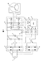
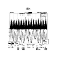
本発明の実施形態に係る同期モータ駆動装置について、図1〜図5を参照しながら以下詳細に説明する。図1は本発明の実施形態に係る同期モータ駆動装置におけるベクトル制御方式の全体回路構成を示す図である。図2は本実施形態に関するベクトル制御演算を構成するブロック図である。図3は本実施形態に関するベクトル制御演算ブロックに含まれる誘起電圧補正手段を示す図である。図4は本実施形態に関する誘起電圧補正手段を適用しない場合におけるU相のモータ電流波形を示す図である。図5は本実施形態に関する誘起電圧補正手段を適用した場合におけるU相のモータ電流波形を示す図である。 A synchronous motor driving apparatus according to an embodiment of the present invention will be described in detail below with reference to FIGS. FIG. 1 is a diagram showing an overall circuit configuration of a vector control system in a synchronous motor driving apparatus according to an embodiment of the present invention. FIG. 2 is a block diagram constituting a vector control calculation relating to the present embodiment. FIG. 3 is a diagram showing the induced voltage correction means included in the vector control calculation block according to this embodiment. FIG. 4 is a diagram showing a U-phase motor current waveform when the induced voltage correction means according to this embodiment is not applied. FIG. 5 is a diagram showing a U-phase motor current waveform when the induced voltage correction means according to this embodiment is applied.
図1において、1は商用電源、2はインダクタンス(リアクトル)、3は整流ダイオード(第1の整流回路)、4は切替リレー(スイッチ)、5〜7は平滑コンデンサ(5,6は分圧コンデンサ、7は平滑コンデンサ)、8は電流検出用抵抗、9はインバータブリッジ回路(インバータ)、10は整流ダイオード(第2の整流回路)、11はスイッチング素子(IGBT等)、12はAD変換器、13〜15はドライバ、16は中央演算処理装置(CPU)、17はマイコン、18は同期モータ(直流ブラシレスモータ)、をそれぞれ表す。
In FIG. 1, 1 is a commercial power source, 2 is an inductance (reactor), 3 is a rectifier diode (first rectifier circuit), 4 is a switching relay (switch), 5-7 are smoothing capacitors (5, 6 are voltage dividing capacitors) , 7 is a smoothing capacitor), 8 is a current detection resistor, 9 is an inverter bridge circuit (inverter), 10 is a rectifier diode (second rectifier circuit), 11 is a switching element (IGBT, etc.), 12 is an AD converter,
図1に示す本実施形態に関する回路構成の動作について説明する。商用電源1からの交流電源は、インダクタンス2を介して整流ダイオード3により整流され、平滑コンデンサ5〜7によって平滑されて直流電源に変換される。インバータブリッジ回路9には直流電源が供給され、インバータブリッジ回路を構成する6個のスイッチング素子のオンオフ動作によって同期モータ18に回転磁界を与え同期モータ18を駆動する。インバータブリッジ回路9がオンオフ動作することで電流検出用抵抗8に電流IDCが流れる。
The operation of the circuit configuration relating to the present embodiment shown in FIG. 1 will be described. The AC power source from the
マイコン17はAD変換器12によってアナログからデジタル化された電流IDCを読込み、ベクトル制御に必要な演算処理を行う。ベクトル制御演算により得られる振幅と位相の正弦波電圧がインバータブリッジ回路9を介して同期モータ18に出力されるようにドライバ15にPWM(Pulse Width Modulation)信号を出力する。また、インバータインバータブリッジ回路9に供給する直流電圧のレベルを変更するため、リレー4を駆動するドライバ13に切り替え信号を出力する。リレー4をオンして分圧コンデンサ6をチャージすることにより倍電圧整流回路が構成される。
The microcomputer 17 reads the current IDC digitized from analog by the
更に、回路の力率を向上させるため、スイッチング素子11を駆動するドライバ14に駆動信号を出力することでインバータインバータブリッジ回路9に供給する直流電圧のレベルが上昇する。このように、マイコン17はAD変換器12によって電流検出用抵抗8に流れる電流IDCを読み込み、ベクトル制御によって同期モータを駆動する。
Furthermore, in order to improve the power factor of the circuit, the level of the DC voltage supplied to the inverter inverter bridge circuit 9 is increased by outputting a drive signal to the driver 14 that drives the switching element 11. As described above, the microcomputer 17 reads the current IDC flowing through the
次に、図2を用いてベクトル制御演算の構成について説明する。20はモータ印加電圧演算、21は2相→3相変換演算、22は誘起電圧補正器、23は位相補正器、24は軸誤差演算器、25は一次遅れフィルタ、26は3相→2相変換演算、27は相電流再現演算、12,15,16は図1と同一である。Id*はd軸電流指令、Iq*はq軸電流指令、f*は周波数指令、Vd*はd軸電圧指令、Vq*はq軸電圧指令、VuはU相モータ電圧、VvはV相モータ電圧、VwはW相モータ電圧、Keは誘起電圧定数(発電定数)、Kecは誘起電圧補正後の定数、θdは軸誤差補正後の電圧位相、Idcはd軸モータ電流、Iqcはq軸モータ電流、Δθはq軸電流指令とq軸モータ電流との軸誤差、IuはU相モータ電流、IwはW相モータ電流、IDCは電流検出用抵抗8に流れる直流電流である。
Next, the configuration of the vector control calculation will be described with reference to FIG. 20 is a motor applied voltage calculation, 21 is a two-phase to three-phase conversion calculation, 22 is an induced voltage corrector, 23 is a phase corrector, 24 is an axis error calculator, 25 is a first-order lag filter, and 26 is three-phase to two-phase. The conversion calculation, 27 is the phase current reproduction calculation, and 12, 15 and 16 are the same as in FIG. Id * is d-axis current command, Iq * is q-axis current command, f * is frequency command, Vd * is d-axis voltage command, Vq * is q-axis voltage command, Vu is U-phase motor voltage, Vv is V-phase motor Voltage, Vw is W phase motor voltage, Ke is induced voltage constant (power generation constant), Kec is constant after induced voltage correction, θd is voltage phase after axis error correction, Idc is d axis motor current, Iqc is q axis motor Current, Δθ is an axis error between the q-axis current command and the q-axis motor current, Iu is a U-phase motor current, Iw is a W-phase motor current, and IDC is a DC current flowing through the
なお、モータ印加電圧演算20は、f*、Id*、Iq*及び補正後の誘起電圧定数Kecを入力とし、Vd*とVq*を出力とし、この入力と出力の関係式は従来知られていることであって、因みに、背景技術欄で引用した特許第3411878号の段落番号0126に記載されている数式で示されている。ここで、Kecはこの数式で使用される定数であり、この定数を本願の図2に示す誘起電圧補正器22の出力で変更することが、後述するが本実施形態の特徴である。
The motor applied
ここにおいて、本実施形態に係る同期モータ駆動装置における構成上の特徴についてまず概説する。本実施形態では、同期モータへの印加電圧を演算する電圧指令演算器(図2のモータ印加電圧演算に対応)に対して、同期モータが回転することで発生する誘起電圧から同期モータの磁極位置を求めた回転座標軸(d−q軸)(実際の回転軸)と、制御上で仮定している回転座標軸(dc−qc軸)(マイコンで仮定して制御したいとしている回転軸)との間に生じる軸誤差Δθによって誘起電圧を補正する補正手段(図2の誘起電圧補正器に対応)を設け、この誘起電圧補正器により演算された誘起電圧補正値ΔKeを、モータ印加電圧を演算する電圧指令演算器に含まれる誘起電圧に加算して最適なモータ印加電圧を演算し、同期モータに供給する駆動制御である。 Here, the structural features of the synchronous motor driving device according to the present embodiment will be outlined first. In the present embodiment, the magnetic pole position of the synchronous motor from the induced voltage generated by the rotation of the synchronous motor with respect to the voltage command calculator (corresponding to the motor applied voltage calculation of FIG. 2) for calculating the applied voltage to the synchronous motor. Between the rotation coordinate axis (dq axis) (actual rotation axis) for which the value is obtained and the rotation coordinate axis (dc-qc axis) assumed on the control (rotation axis assumed to be controlled by the microcomputer) Is provided with a correction means (corresponding to the induced voltage corrector in FIG. 2) for correcting the induced voltage by the axis error Δθ generated in the motor, and the induced voltage correction value ΔKe calculated by the induced voltage corrector is used as a voltage for calculating the motor applied voltage. This is drive control that calculates the optimum motor applied voltage by adding to the induced voltage included in the command calculator and supplies it to the synchronous motor.
定性的に説明すると、同期モータが回転することによって固定子巻線に発生する誘起電圧は、Ke・ω1(2πf1)で決まるが、この周波数f1に対応した誘起電圧と等しい値の誘起電圧が発生していないと軸ずれを起こしていると云える。発生している誘起電圧が当該f1対応の誘起電圧よりも高いと云うことは実際の回転数が制御したい回転数よりも高くなっていて磁極位置が進んでいることを表している。この場合には、同期モータへの制御出力としてモータ印加電圧が不足していることになるので、誘起電圧が高くなった分の補正値をプラスして同期モータに印加することとなる。そして、従来技術では軸誤差Δθを求めてこのΔθによってモータの回転速度を直接に制御するものであったのに対して、本実施形態では、モータの脈動に基づいた誘起電圧の補正値を用いてモータに印加する電圧を対象として制御するものであるので、モータの回転脈動を軽減することができるものである。 To explain qualitatively, the induced voltage generated in the stator winding by the rotation of the synchronous motor is determined by Ke · ω 1 (2πf 1 ), but the induced voltage is equal to the induced voltage corresponding to this frequency f 1. If no voltage is generated, it can be said that the axis is displaced. The fact that the generated induced voltage is higher than the induced voltage corresponding to f 1 indicates that the actual rotational speed is higher than the rotational speed to be controlled and the magnetic pole position is advanced. In this case, since the motor applied voltage is insufficient as the control output to the synchronous motor, the correction value corresponding to the increase of the induced voltage is added and applied to the synchronous motor. In the prior art, the shaft error Δθ is obtained and the rotational speed of the motor is directly controlled by this Δθ. In the present embodiment, a correction value of the induced voltage based on the pulsation of the motor is used. Therefore, since the voltage applied to the motor is controlled, the rotational pulsation of the motor can be reduced.
具体的には、図2と図3の説明で詳述するが、同期モータの磁極位置を基準とした回転座標軸(d−q軸)と、制御上で仮定している回転座標軸(dc−qc軸)との間に生じる軸誤差Δθを軸誤差演算器24により演算する。誘起電圧補正器22は、この軸誤差演算器24により演算された軸誤差Δθに補正ゲイン28を乗算し、誘起電圧補正値ΔKeとする。その際、軸誤差Δθの値が同期モータの磁極位置を基準とした回転座標軸(d−q軸)に対し、制御上で仮定している回転座標軸(dc−qc軸)が進んでいるという場合、制御側の周波数指令f*に対して同期モータが遅れている状態で、同期モータの誘起電圧値が制御上で認識している誘起電圧値よりも小さく、同期モータに対して過剰にモータ印加電圧(20の出力)を与えていることになる。従って、誘起電圧補正値をマイナス値とする。
Specifically, as will be described in detail with reference to FIGS. 2 and 3, the rotational coordinate axes (dq axes) based on the magnetic pole position of the synchronous motor and the rotational coordinate axes (dc-qc) assumed in the control. The axis error Δθ generated between the axis error and the axis) is calculated by the
逆に、軸誤差Δθの値が同期モータの磁極位置を基準とした回転座標軸(d−q軸)に対し、制御上で仮定している回転座標軸(dc−qc軸)が遅れているという場合、制御側の周波数指令f*に対して同期モータが進んでいる状態で、同期モータの誘起電圧値が制御上で認識している誘起電圧値より大きく、同期モータに対してモータ印加電圧(20の出力)が不足している。従って、誘起電圧補正値ΔKeをプラス値とする。 Conversely, when the value of the axis error Δθ is behind the rotational coordinate axis (dc-qc axis) assumed in the control with respect to the rotational coordinate axis (dq axis) based on the magnetic pole position of the synchronous motor. In the state where the synchronous motor is advanced with respect to the frequency command f * on the control side, the induced voltage value of the synchronous motor is larger than the induced voltage value recognized in the control, and the motor applied voltage (20 Output) is insufficient. Therefore, the induced voltage correction value ΔKe is a positive value.
この誘起電圧補正器22により演算された誘起電圧補正値ΔKeをモータ印加電圧を演算する電圧指令演算器20に含まれる誘起電圧に加算して最適なモータ印加電圧を演算し、同期モータに供給することである。
The induced voltage correction value ΔKe calculated by the induced
続いて、ベクトル制御演算の内容について説明する。図2は、本実施形態の特徴である誘起電圧補正器22を除いて、ベクトル制御演算として一般的な計算を示したものである。各演算ブロックの計算式は電気工学ハンドブックの第594頁〜第596頁(2001年2月20日発行)に示されているので説明は省略する。モータ印加電圧演算20は、d軸電流指令Id*、周波数指令f*、q軸モータ電流Iqcを一次遅れフィルタ25を介して平滑/平均化されたq軸電流指令Iq*に基づいて、d軸電圧指令Vd*、q軸電圧指令Vq*を算出する。
Subsequently, the contents of the vector control calculation will be described. FIG. 2 shows a general calculation as a vector control operation except for the induced
誘起電圧補正器22は、誘起電圧定数Keに軸誤差演算器24により算出された軸誤差Δθに基づいて補正値を求め、それを加算して誘起電圧補正後の定数Kecを算出する。位相補正器23は、周波数指令f*に比例させてモータ電圧位相の基準値θを求め、軸誤差演算器24により算出された軸誤差Δθを加算してモータ電圧位相の瞬時値θdとする。この軸誤差補正後の電圧位相θdを2相→3相変換演算21に印加する。2相→3相変換演算21は、電圧位相θd、d軸電圧指令Vd*、q軸電圧指令Vq*より、U相モータ電圧Vu、V相モータ電圧Vv、W相モータ電圧Vwを算出する。
The induced
軸誤差演算器24は、同期モータの磁極位置を求めた回転座標軸(d−q軸)と、制御上で仮定している回転座標軸(dc−qc軸)との間に生じる軸誤差Δθを算出する。相電流再現演算27は、AD変換器12によって電流検出用抵抗8に流れる直流電流IDCを読み込み、U相モータ電流Iu、W相モータ電流Iwを算出する。3相→2相変換演算26は、U相モータ電流Iuの、W相モータ電流Iwのからq軸モータ電流Iqc、d軸モータ電流Idcを算出する。
The
また、直流電流IDCが読めなかった場合、IuとIwが再現できない。そこで、前回有効のIuとIwから求めたq軸モータ電流Iqc、d軸モータ電流Idcを基に、Iuの値、Iwの値を求めておき、相電流再現演算27にて相電流が再現できなかった場合に、このIuとIwの値で代用する。一次遅れフィルタ25は、q軸電流指令Iq*算出用であり、q軸モータ電流Iqcを一次遅れフィルタ処理しq軸電流指令Iq*とする。
Also, if the DC current IDC cannot be read, Iu and Iw cannot be reproduced. Therefore, based on the q-axis motor current Iqc and d-axis motor current Idc obtained from the previously effective Iu and Iw, the values of Iu and Iw are obtained, and the phase current can be reproduced by the phase current reproduction calculation 27. If not, the values of Iu and Iw are substituted. The first-
次に、図3を用いて、本実施形態の構成上の特徴である誘起電圧補正器22について説明する。28は補正ゲインKp、29は加算器であり、22は図2と同一である。Δθは同期モータの磁極位置を求めた回転座標軸(d−q軸)と、制御上で仮定している回転座標軸(dc−qc軸)との間に生じる軸誤差、Keは同期モータが回転することで発生する誘起電圧の定数、ΔKeは軸誤差Δθに補正ゲインKpを乗算した値である。
Next, the induced
補正ゲインKp28は、軸誤差Δθに補正ゲインKpを乗算し誘起電圧補正値ΔKeを出力する。加算器29は、この誘起電圧補正値ΔKeと基準の誘起電圧定数(基準の発電定数)Keを加算して誘起電圧補正後の誘起電圧定数(発電定数)Kecとする。
The correction gain Kp28 multiplies the axis error Δθ by the correction gain Kp and outputs an induced voltage correction value ΔKe. The
次に、図4と図5に示す電流波形について説明する。図4は、誘起電圧補正手段の無い従来の駆動装置で、低回転数かつ高負荷状態で同期モータを駆動した際のU相のモータ電流波形である(U相に限らずどの相でも同様な波形)。図を見ても判るようにモータ電流がある一定の周期で脈動している。 Next, the current waveforms shown in FIGS. 4 and 5 will be described. FIG. 4 shows a U-phase motor current waveform when a synchronous motor is driven at a low rotational speed and a high load state in a conventional drive device without induced voltage correction means (the same applies to any phase, not limited to the U phase). Waveform). As can be seen from the figure, the motor current pulsates at a certain cycle.
図5は、図4と全く同じ条件で、本実施形態で採用する誘起電圧補正手段を用いた駆動装置で同期モータを駆動させた場合の波形である。図を見ても判るように誘起電圧補正手段を用いることでモータ電流の脈動が軽減されている。さらに、図3に示す誘起電圧補正器24内の補正ゲインKpを調整することで、モータ電流の脈動を一層抑制することも可能である。これによって、軸誤差Δθがほぼ零に近づくこととなり、モータの回転数の脈動が軽減され、安定した駆動制御ができようになる。
FIG. 5 shows waveforms when the synchronous motor is driven by the drive device using the induced voltage correction means employed in the present embodiment under exactly the same conditions as FIG. As can be seen from the figure, the pulsation of the motor current is reduced by using the induced voltage correction means. Furthermore, the pulsation of the motor current can be further suppressed by adjusting the correction gain Kp in the induced
1:商用電源、2:インダクタンス(リアクトル)、3:は整流ダイオード(第1の整流回路)、4:切替リレー(スイッチ)、5〜6:分圧コンデンサ、7:平滑コンデンサ、8:電流検出用抵抗、9:インバータブリッジ回路(インバータ)、10:整流ダイオード(第2の整流回路)、11:スイッチング素子(IGBT等)、12:AD変換器、13〜15:ドライバ、16:中央演算処理装置、17:マイコン、18:同期モータ(直流ブラシレスモータ)、20:モータ印加電圧演算、21:2相→3相変換演算、22:誘起電圧補正器、23:位相補正器、24:軸誤差演算器、25:一次遅れフィルタ、26:3相→2相変換演算、27:相電流再現演算、Id*:d軸電流指令、Iq*:q軸電流指令、f*:周波数指令、Vd*:d軸電圧指令、Vq*:q軸電圧指令、Vu:U相モータ電圧、Vv:V相モータ電圧、Vw:W相モータ電圧、Ke:誘起電圧定数、Kec:誘起電圧補正後の定数、θd:軸誤差補正後の電圧位相、Idc:d軸モータ電流、Iqc:q軸モータ電流、Δθ:同期モータの磁極位置と制御上の磁極位置との軸誤差、Iu:U相モータ電流、Iw:W相モータ電流、IDC:電流検出用抵抗8に流れる直流電流、22:誘起電圧補正器、28:補正ゲイン、29:加算器、Δθ:同期モータの磁極位置と制御上の磁極位置との軸誤差、Ke:誘起電圧の定数、ΔKe:誘起電圧補正値、Kec:誘起電圧補正後の定数 1: commercial power supply, 2: inductance (reactor), 3: rectifier diode (first rectifier circuit), 4: switching relay (switch), 5-6: voltage dividing capacitor, 7: smoothing capacitor, 8: current detection Resistance: 9: inverter bridge circuit (inverter), 10: rectifier diode (second rectifier circuit), 11: switching element (IGBT, etc.), 12: AD converter, 13-15: driver, 16: central processing Device: 17: Microcomputer, 18: Synchronous motor (DC brushless motor), 20: Motor applied voltage calculation, 21: Two-phase to three-phase conversion calculation, 22: Induced voltage corrector, 23: Phase corrector, 24: Axis error Arithmetic unit, 25: primary delay filter, 26: three-phase to two-phase conversion calculation, 27: phase current reproduction calculation, Id *: d-axis current command, Iq *: q-axis current command, f *: frequency command Vd *: d-axis voltage command, Vq *: q-axis voltage command, Vu: U-phase motor voltage, Vv: V-phase motor voltage, Vw: W-phase motor voltage, Ke: induced voltage constant, Kec: after induced voltage correction Constant, θd: Voltage phase after axis error correction, Idc: d-axis motor current, Iqc: q-axis motor current, Δθ: Axis error between synchronous motor magnetic pole position and control magnetic pole position, Iu: U-phase motor current , Iw: W-phase motor current, IDC: DC current flowing through the current detection resistor 8, 22: induced voltage corrector, 28: correction gain, 29: adder, Δθ: synchronous motor magnetic pole position and control magnetic pole position Error, Ke: constant of induced voltage, ΔKe: induced voltage correction value, Kec: constant after induced voltage correction
Claims (4)
ベクトル制御におけるd軸電流指令Id、q軸電流指令Iq、周波数指令f及び誘起電圧定数Keを入力とし、d軸電圧指令Vd、q軸電圧指令Vqを出力するモータ印加電圧演算部を有し、
同期モータの磁極位置を基準とした回転座標軸(d−q軸)と制御上で仮定している回転座標軸(dc−qc軸)との間に発生する軸誤差Δθに基づいて前記誘起電圧定数Keを補正する誘起電圧補正部を設け、
前記誘起電圧補正部で補正した誘起電圧定数を前記モータ印加電圧演算部に入力する
ことを特徴とする同期モータの駆動装置。 In a synchronous motor drive device that performs speed control with a position sensorless vector control method,
A motor applied voltage calculation unit that receives the d-axis current command Id, the q-axis current command Iq, the frequency command f, and the induced voltage constant Ke in vector control and outputs the d-axis voltage command Vd and the q-axis voltage command Vq;
The induced voltage constant Ke is based on an axis error Δθ generated between a rotational coordinate axis (dq axis) based on the magnetic pole position of the synchronous motor and a rotational coordinate axis (dc-qc axis) assumed in the control. An induced voltage correction unit for correcting
An apparatus for driving a synchronous motor, wherein the induced voltage constant corrected by the induced voltage correction unit is input to the motor applied voltage calculation unit.
ベクトル制御におけるd軸電流指令Id、q軸電流指令Iq、周波数指令f及び誘起電圧定数Keを入力とし、d軸電圧指令Vd、q軸電圧指令Vqを出力するモータ印加電圧演算部を有し、
前記d軸電圧指令Vd、前記q軸電圧指令Vq、前記周波数指令に比例したモータ電圧位相基準値θに前記軸誤差Δθを加算したモータ電圧位相瞬時値θdを入力とし、U相モータ電圧Vu、V相モータ電圧Vv、W相モータ電圧Vwを出力する2相−3相変換演算部を有し、
同期モータの磁極位置を基準とした回転座標軸(d−q軸)と制御上で仮定している回転座標軸(dc−qc軸)との間に発生する軸誤差Δθに基づいて前記誘起電圧定数Keを補正する誘起電圧補正部を設け、
前記誘起電圧補正部で補正した誘起電圧定数を前記モータ印加電圧演算部に入力することで、モータ電流の脈動を軽減させる
ことを特徴とする同期モータの駆動装置。 In a synchronous motor drive device that performs speed control with a position sensorless vector control method,
A motor applied voltage calculation unit that receives the d-axis current command Id, the q-axis current command Iq, the frequency command f, and the induced voltage constant Ke in vector control and outputs the d-axis voltage command Vd and the q-axis voltage command Vq;
The d-axis voltage command Vd, the q-axis voltage command Vq, the motor voltage phase instantaneous value θd obtained by adding the shaft error Δθ to the motor voltage phase reference value θ proportional to the frequency command, and the U-phase motor voltage Vu, It has a two-phase to three-phase conversion operation unit that outputs a V-phase motor voltage Vv and a W-phase motor voltage Vw,
The induced voltage constant Ke is based on an axis error Δθ generated between a rotational coordinate axis (dq axis) based on the magnetic pole position of the synchronous motor and a rotational coordinate axis (dc-qc axis) assumed in the control. An induced voltage correction unit for correcting
A synchronous motor drive device characterized by reducing the pulsation of the motor current by inputting the induced voltage constant corrected by the induced voltage correction unit to the motor applied voltage calculation unit.
前記誘起電圧補正部は、前記軸誤差Δθに補正ゲインKpを乗算して誘起電圧補正値ΔKeとし、入力された基準の誘起電圧定数Keに前記誘起電圧補正値ΔKeを加算して、補正後の誘起電圧定数として出力する
ことを特徴とする同期モータの駆動装置。 In claim 1 or 2,
The induced voltage correction unit multiplies the axis error Δθ by a correction gain Kp to obtain an induced voltage correction value ΔKe, and adds the induced voltage correction value ΔKe to the input reference induced voltage constant Ke to obtain a corrected value. A synchronous motor driving device characterized in that it outputs as an induced voltage constant.
前記補正ゲインKpの値を調整することによって前記モータ電流の脈動軽減を微調整することを特徴とする同期モータの駆動装置。 In claim 3,
A synchronous motor driving device, wherein the motor current pulsation reduction is finely adjusted by adjusting the value of the correction gain Kp.
Priority Applications (1)
| Application Number | Priority Date | Filing Date | Title |
|---|---|---|---|
| JP2006350161A JP2008161027A (en) | 2006-12-26 | 2006-12-26 | Drive unit of synchronous motor |
Applications Claiming Priority (1)
| Application Number | Priority Date | Filing Date | Title |
|---|---|---|---|
| JP2006350161A JP2008161027A (en) | 2006-12-26 | 2006-12-26 | Drive unit of synchronous motor |
Publications (1)
| Publication Number | Publication Date |
|---|---|
| JP2008161027A true JP2008161027A (en) | 2008-07-10 |
Family
ID=39661284
Family Applications (1)
| Application Number | Title | Priority Date | Filing Date |
|---|---|---|---|
| JP2006350161A Withdrawn JP2008161027A (en) | 2006-12-26 | 2006-12-26 | Drive unit of synchronous motor |
Country Status (1)
| Country | Link |
|---|---|
| JP (1) | JP2008161027A (en) |
Cited By (2)
| Publication number | Priority date | Publication date | Assignee | Title |
|---|---|---|---|---|
| JP2012110171A (en) * | 2010-11-19 | 2012-06-07 | Hitachi Appliances Inc | Motor controller, and air conditioner |
| KR20150013150A (en) * | 2012-05-04 | 2015-02-04 | 이턴 코포레이션 | System and method for ground fault detection and protection in adjustable speed drives |
-
2006
- 2006-12-26 JP JP2006350161A patent/JP2008161027A/en not_active Withdrawn
Cited By (3)
| Publication number | Priority date | Publication date | Assignee | Title |
|---|---|---|---|---|
| JP2012110171A (en) * | 2010-11-19 | 2012-06-07 | Hitachi Appliances Inc | Motor controller, and air conditioner |
| KR20150013150A (en) * | 2012-05-04 | 2015-02-04 | 이턴 코포레이션 | System and method for ground fault detection and protection in adjustable speed drives |
| KR102024821B1 (en) | 2012-05-04 | 2019-11-14 | 이턴 코포레이션 | System and method for ground fault detection and protection in adjustable speed drives |
Similar Documents
| Publication | Publication Date | Title |
|---|---|---|
| JP5130716B2 (en) | Motor control device and electric power steering device | |
| JP4988329B2 (en) | Beatless control device for permanent magnet motor | |
| JP3611492B2 (en) | Inverter control method and apparatus | |
| JP3661642B2 (en) | Motor control device and control method thereof | |
| JP4918483B2 (en) | Inverter device | |
| JP5549384B2 (en) | Electric motor control device and electric motor control system | |
| JP2007166690A (en) | Motor control device | |
| JP2014200154A (en) | Motor controller and magnetic pole position estimation method | |
| JPWO2019008676A1 (en) | Inverter device and electric power steering device | |
| JP6644172B2 (en) | Motor control device | |
| TW201820769A (en) | Inverter control device and motor drive system | |
| WO2016006386A1 (en) | Control device and control method for vehicle dynamo | |
| JP2004289926A (en) | Motor controller | |
| JP6129972B2 (en) | AC motor control device, AC motor drive system, fluid pressure control system, positioning system | |
| JP2014180148A (en) | Motor controller | |
| JP5278326B2 (en) | Inverter control device and control method thereof | |
| JP4596906B2 (en) | Electric motor control device | |
| JP2020048249A (en) | Steering device | |
| JP2004061217A (en) | Current detecting device, method thereof, and electric motor | |
| JP2011217575A (en) | Power conversion apparatus | |
| JP2008161027A (en) | Drive unit of synchronous motor | |
| JP6590196B2 (en) | Power converter | |
| JP2013172550A (en) | Motor controller and three-phase voltage command generating method of motor | |
| JP4446688B2 (en) | Multiphase current supply circuit and control method thereof | |
| JP2010022189A (en) | Position sensorless control circuit for motor |
Legal Events
| Date | Code | Title | Description |
|---|---|---|---|
| A621 | Written request for application examination |
Free format text: JAPANESE INTERMEDIATE CODE: A621 Effective date: 20081024 |
|
| A761 | Written withdrawal of application |
Free format text: JAPANESE INTERMEDIATE CODE: A761 Effective date: 20090610 |