JP2008137601A - Roof storage type vehicle - Google Patents
Roof storage type vehicle Download PDFInfo
- Publication number
- JP2008137601A JP2008137601A JP2006328312A JP2006328312A JP2008137601A JP 2008137601 A JP2008137601 A JP 2008137601A JP 2006328312 A JP2006328312 A JP 2006328312A JP 2006328312 A JP2006328312 A JP 2006328312A JP 2008137601 A JP2008137601 A JP 2008137601A
- Authority
- JP
- Japan
- Prior art keywords
- roof
- vehicle
- tonneau cover
- width direction
- roof storage
- Prior art date
- Legal status (The legal status is an assumption and is not a legal conclusion. Google has not performed a legal analysis and makes no representation as to the accuracy of the status listed.)
- Pending
Links
Images


Classifications
-
- B—PERFORMING OPERATIONS; TRANSPORTING
- B60—VEHICLES IN GENERAL
- B60J—WINDOWS, WINDSCREENS, NON-FIXED ROOFS, DOORS, OR SIMILAR DEVICES FOR VEHICLES; REMOVABLE EXTERNAL PROTECTIVE COVERINGS SPECIALLY ADAPTED FOR VEHICLES
- B60J7/00—Non-fixed roofs; Roofs with movable panels, e.g. rotary sunroofs
- B60J7/20—Vehicle storage compartments for roof parts or for collapsible flexible tops
- B60J7/202—Vehicle storage compartments for roof parts or for collapsible flexible tops being characterised by moveable cover parts for closing the gap between boot lid and rearmost seats
-
- B—PERFORMING OPERATIONS; TRANSPORTING
- B60—VEHICLES IN GENERAL
- B60J—WINDOWS, WINDSCREENS, NON-FIXED ROOFS, DOORS, OR SIMILAR DEVICES FOR VEHICLES; REMOVABLE EXTERNAL PROTECTIVE COVERINGS SPECIALLY ADAPTED FOR VEHICLES
- B60J1/00—Windows; Windscreens; Accessories therefor
- B60J1/18—Windows; Windscreens; Accessories therefor arranged at the vehicle rear
- B60J1/1807—Windows; Windscreens; Accessories therefor arranged at the vehicle rear movable for vehicles with convertible top
- B60J1/1823—Windows; Windscreens; Accessories therefor arranged at the vehicle rear movable for vehicles with convertible top adjustable relative to hard- or soft-top, e.g. pivotable
- B60J1/183—Windows; Windscreens; Accessories therefor arranged at the vehicle rear movable for vehicles with convertible top adjustable relative to hard- or soft-top, e.g. pivotable slidable
-
- B—PERFORMING OPERATIONS; TRANSPORTING
- B60—VEHICLES IN GENERAL
- B60J—WINDOWS, WINDSCREENS, NON-FIXED ROOFS, DOORS, OR SIMILAR DEVICES FOR VEHICLES; REMOVABLE EXTERNAL PROTECTIVE COVERINGS SPECIALLY ADAPTED FOR VEHICLES
- B60J7/00—Non-fixed roofs; Roofs with movable panels, e.g. rotary sunroofs
- B60J7/08—Non-fixed roofs; Roofs with movable panels, e.g. rotary sunroofs of non-sliding type, i.e. movable or removable roofs or panels, e.g. let-down tops or roofs capable of being easily detached or of assuming a collapsed or inoperative position
- B60J7/12—Non-fixed roofs; Roofs with movable panels, e.g. rotary sunroofs of non-sliding type, i.e. movable or removable roofs or panels, e.g. let-down tops or roofs capable of being easily detached or of assuming a collapsed or inoperative position foldable; Tensioning mechanisms therefor, e.g. struts
- B60J7/14—Non-fixed roofs; Roofs with movable panels, e.g. rotary sunroofs of non-sliding type, i.e. movable or removable roofs or panels, e.g. let-down tops or roofs capable of being easily detached or of assuming a collapsed or inoperative position foldable; Tensioning mechanisms therefor, e.g. struts with a plurality of rigid plate-like elements or rigid non plate-like elements, e.g. with non-slidable, but pivotable or foldable movement
- B60J7/143—Non-fixed roofs; Roofs with movable panels, e.g. rotary sunroofs of non-sliding type, i.e. movable or removable roofs or panels, e.g. let-down tops or roofs capable of being easily detached or of assuming a collapsed or inoperative position foldable; Tensioning mechanisms therefor, e.g. struts with a plurality of rigid plate-like elements or rigid non plate-like elements, e.g. with non-slidable, but pivotable or foldable movement for covering the passenger compartment
- B60J7/148—Non-fixed roofs; Roofs with movable panels, e.g. rotary sunroofs of non-sliding type, i.e. movable or removable roofs or panels, e.g. let-down tops or roofs capable of being easily detached or of assuming a collapsed or inoperative position foldable; Tensioning mechanisms therefor, e.g. struts with a plurality of rigid plate-like elements or rigid non plate-like elements, e.g. with non-slidable, but pivotable or foldable movement for covering the passenger compartment at least one element being stored in vertical fashion
Landscapes
- Engineering & Computer Science (AREA)
- Mechanical Engineering (AREA)
- Vehicle Step Arrangements And Article Storage (AREA)
- Body Structure For Vehicles (AREA)
Abstract
Description
本発明は、ルーフを車体内部に格納してオープントップ状態とすることが可能なルーフ格納型車両に関し、さらに詳しくは、座席の後方に画成されたルーフ格納部を開閉するためのトノカバーを備えたルーフ格納型車両に関する。 The present invention relates to a roof retractable vehicle that can be stored in an open top state by storing a roof inside a vehicle body, and more specifically, includes a tonneau cover for opening and closing a roof storage portion defined behind a seat. The present invention relates to a roof retractable vehicle.
ルーフを車体内部に格納してオープントップ状態とすることが可能なルーフ格納型車両としては、ルーフを分割して車体内部に格納するハードトップタイプと、ルーフを折畳んで格納するソフトトップタイプがある。このような車両は、ルーフを格納してオープントップ状態とした場合およびルーフを展開しクローズドトップ状態とした場合に、座席後方のルーフ格納部を閉鎖するトノカバーを備えている。 There are two types of roof retractable vehicles that can be stored in the open top state by storing the roof inside the vehicle body, and the hard top type that divides the roof and stores it inside the vehicle body, and the soft top type that stores the roof folded. is there. Such a vehicle includes a tonneau cover that closes the roof storage portion at the rear of the seat when the roof is stored in an open top state and when the roof is expanded to a closed top state.
このトノカバーとしては、人為的な操作で開閉させる取外し式や巻取り式などの手動式トノカバー(例えば特許文献1参照)、ルーフ格納機構と連動して駆動される自動式トノカバー等があるが、手動式は操作性や外観等に問題がある。自動式トノカバーとしては、ルーフをトランクに格納する車両においてトノカバーシステムがトランクリッドに装着されており、持ち上がったトランクリッドからトノカバーが現れるタイプや、専用のリッドが設置されているタイプ、ルーフ開放時と閉鎖時で別のカバーが現れるタイプ(特許文献2参照)、カバーを車幅方向の軸回りに山折りにしスライドレールに沿って摺動させるタイプ(特許文献3、4参照)などが公知である。これらはいずれも構造が複雑で多数の部品を必要とするため製造コストを要する問題がある。さらに、駆動機構が大掛かりであるためデッドスペースが大きくなるという問題もあった。
Examples of the tonneau cover include a manual tonneau cover such as a detachable type and a retractable type that are manually opened and closed (see, for example, Patent Document 1), and an automatic tonneau cover that is driven in conjunction with a roof storage mechanism. The formula has problems in operability and appearance. As an automatic tonneau cover, a tonneau cover system is mounted on the trunk lid in a vehicle storing the roof in the trunk, a type in which the tonneau cover appears from the raised trunk lid, a type in which a dedicated lid is installed, and when the roof is opened A type in which another cover appears at the time of closing (see Patent Document 2), a type in which the cover is folded around a shaft in the vehicle width direction and slid along the slide rail (see
本発明はこのような実状に鑑みてなされたものであって、その目的は、トノカバー開閉機構の構造および動作が簡素で、開閉時における移動量が小さく、駆動機構の設置スペースも小さいうえ、製造コストを低減可能なルーフ格納型車両を提供することにある。 The present invention has been made in view of such circumstances, and its purpose is to simplify the structure and operation of the tonneau cover opening and closing mechanism, to reduce the amount of movement during opening and closing, to reduce the installation space of the drive mechanism, and to manufacture The object is to provide a roof retractable vehicle capable of reducing the cost.
上記課題を解決するため、本発明のルーフ格納型車両は、座席の後方に画成されたルーフ格納部と、前記ルーフ格納部にルーフを格納するためのルーフ格納機構と、前記ルーフ格納部の上部を開閉するためのトノカバーとを備えたルーフ格納型車両において、前記トノカバーが車体側に対して機構的に連結され、前記トノカバーの前端が閉鎖位置から前方かつ上方に移動するとともに、前記トノカバーの後端が前方に移動する動作によって、前記トノカバーが前記閉鎖位置から車両前方側に傾斜姿勢で退避し、前記ルーフ格納部の上部が開放されるように構成されている。 In order to solve the above problems, a roof storage type vehicle according to the present invention includes a roof storage portion defined behind a seat, a roof storage mechanism for storing a roof in the roof storage portion, and a roof storage portion. In a roof retractable vehicle including a tonneau cover for opening and closing an upper portion, the tonneau cover is mechanically connected to the vehicle body side, and a front end of the tonneau cover moves forward and upward from a closed position. By the movement of the rear end moving forward, the tonneau cover is retracted in an inclined posture from the closed position to the vehicle front side, and the upper portion of the roof storage portion is opened.
上記構成により、トノカバーをルーフの移動軌跡に沿った傾斜姿勢で退避させることで、少ない移動量で確実にルーフとの干渉を防止でき、かつ、移動量に比較して大きな開閉領域を得ることができる。また、トノカバーの前端は室内空間側への移動となるが、上方に移動することで室内空間への突出量は小さく、居住性への影響を最小限に留めることができる。さらに、トノカバーの後端は車両前後方向に移動して、ルーフ閉鎖状態ではルーフ後面(バックウインド)に接離し、ルーフ格納状態ではルーフ格納部の開口縁部に接離する動作によって、いずれの場合にも良好なシールを確立できる。 With the above configuration, by retracting the tonneau cover in an inclined posture along the movement trajectory of the roof, interference with the roof can be reliably prevented with a small amount of movement, and a large opening / closing region can be obtained compared to the amount of movement. it can. Further, the front end of the tonneau cover moves toward the indoor space side, but by moving upward, the amount of protrusion into the indoor space is small, and the influence on the comfort can be kept to a minimum. Furthermore, the rear end of the tonneau cover moves in the longitudinal direction of the vehicle, touches and separates from the rear surface of the roof (back window) when the roof is closed, and moves toward and away from the opening edge of the roof storage portion in either case. A good seal can be established.
本発明の好適な態様では、前記トノカバーが、車幅方向の中央に位置した中央部材とその両側に隣接した各側部材で構成され、前記中央部材が車体側に対して機構的に連結され、前記各側部材は前記中央部材にそれぞれ回動または摺動可能に連結され、車幅方向中央側へ引込み可能であるので、ルーフ格納機構を構成するリンクやルーフの側面部分の移動経路が車両側部に確保され、一層少ない移動量で迅速かつ確実にルーフの移動軌跡から退避させることができる。また、ルーフ格納部の車両側方における開口縁部に対して前記各側部材が接離する動作が可能となり、車両側方に良好なシールを確立できる。 In a preferred aspect of the present invention, the tonneau cover is composed of a central member located in the center in the vehicle width direction and side members adjacent to both sides thereof, and the central member is mechanically connected to the vehicle body side, Each side member is pivotably or slidably connected to the central member and can be retracted toward the center in the vehicle width direction. Therefore, the movement path of the link constituting the roof storage mechanism and the side surface portion of the roof is on the vehicle side. It is ensured in the part and can be retreated from the movement locus of the roof quickly and reliably with a smaller movement amount. In addition, the side members can be brought into and out of contact with the opening edge portion on the vehicle side of the roof storage portion, and a good seal can be established on the vehicle side.
前記トノカバーの前記各側部材が前記中央部材に分割線に沿って回動可能に連結され、該回動軸が、車両前後方向の前端が後端よりも車両中央側に位置するように斜めに配向されている態様では、トノカバーを閉鎖位置から退避させた傾斜姿勢において、中央部材の上端側の幅が狭くなり、一般的なルーフの内面形状に沿って、少ない移動量でルーフの移動軌跡から退避させることができる。
また、車幅方向両側部に配設されるルーフ格納機構の揺動範囲を確保すべく、トノカバーの各側部材先端を中央部材に比べて車両前方に延出させる場合に、上記傾斜姿勢での各側部材の揺動によって該各側部材の先端位置を下げ、ルーフ移動軌跡から退避させることができる。
その際、各側部材先端の車両前方側位置が下がるのに対し、各側部材先端の車両後方側は揺動軸に近く降下量が小さくなるため、トノカバーの開放動作の初期に、中央部材の傾斜角が小さい状態で、各側部材の揺動を開始することが可能になる。これは、各側部材を中央部材に機構的に連動させる場合に有利である。
The side members of the tonneau cover are connected to the central member so as to be rotatable along a dividing line, and the rotational shaft is inclined so that the front end in the vehicle front-rear direction is located closer to the vehicle center than the rear end. In the orientation mode, in the inclined posture in which the tonneau cover is retracted from the closed position, the width of the upper end side of the central member becomes narrower, and the general movement of the inner surface of the roof can be reduced by a small amount of movement from the roof movement trajectory. Can be evacuated.
In addition, in order to secure the swing range of the roof retracting mechanism disposed on both sides in the vehicle width direction, when the front end of each side member of the tonneau cover is extended forward of the vehicle compared to the central member, By swinging each side member, the tip position of each side member can be lowered and retracted from the roof movement locus.
At that time, the vehicle front side position at the end of each side member is lowered, while the vehicle rear side at the end of each side member is close to the swing shaft and the amount of lowering is small. It is possible to start swinging of each side member in a state where the inclination angle is small. This is advantageous when each side member is mechanically interlocked with the central member.
前記トノカバーの前記中央部材が、車両前後方向に離間した2位置において、それぞれリンクを介して車体側に揺動可能に連結され、該前後各側のリンクと前記中央部材とが、車体側を固定節とする4節リンク機構を構成し、かつ、前側リンクの車体側揺動軸が後側リンクの車体側揺動軸よりも高位置に配設されている態様では、上述したトノカバーの開閉を確定動作で軽快に実施することができる。 The central member of the tonneau cover is slidably connected to the vehicle body side via links at two positions spaced apart in the vehicle front-rear direction, and the links on the front and rear sides and the central member fix the vehicle body side. In a mode in which a four-bar linkage mechanism is used as a node and the vehicle body side swing shaft of the front link is disposed at a higher position than the vehicle body side swing shaft of the rear link, the above-described tonneau cover is opened and closed. It can be carried out lightly with a definite operation.
前記トノカバーの前記各側部材が、前記前側リンクまたは車体側に連結部材を介して連結され、前記トノカバーの閉鎖位置から開放位置への移動によって、前記各側部材が車幅方向中央側へ引込まれるように構成されている態様では、別途駆動源を必要とせずに、中央部材の移動に連動して各側部材を適正なタイミングで引込むことができる。 Each side member of the tonneau cover is connected to the front link or the vehicle body side via a connecting member, and the side member is pulled to the center in the vehicle width direction by moving the tonneau cover from the closed position to the open position. In the configuration configured as described above, each side member can be pulled in at an appropriate timing in conjunction with the movement of the central member without requiring a separate drive source.
また、前記トノカバーが、前記各側部材を前記中央部材に対して前記引込み方向と反対方向に付勢する付勢部材と、該付勢部材の付勢力に抗して前記各側部材の回動範囲を規制する規制手段とを備えている態様では、トノカバーを開放位置から閉鎖位置に復帰させる際に付勢部材の付勢力で各側部材を伸展させることができ、先述した各側部材の連結部材には専ら引張力のみが作用し、連結部材を簡素化、軽量化できる。また、格納動作時における各側部材の不要な振動を防止できる。 The tonneau cover urges each side member against the central member in a direction opposite to the retracting direction, and the side member rotates against the urging force of the urging member. In the aspect provided with the regulating means for regulating the range, each side member can be extended by the biasing force of the biasing member when the tonneau cover is returned from the open position to the closed position. Only the tensile force acts exclusively on the member, and the connecting member can be simplified and reduced in weight. Further, unnecessary vibration of each side member during the storing operation can be prevented.
さらに、前記座席とルーフ格納部との間に車幅方向に延設されたフレーム構造体を備え、該フレーム構造体の車幅方向中央部に、前記トノカバーを閉鎖位置と開放位置との間で移動させる駆動手段が配設されている態様では、車体の剛性が向上し、オープンルーフタイプの車両の安全性や操縦性を向上可能であるとともに、トノカバーに近接した剛性の高い部位に駆動手段が配設されることで、トノカバーを効率良く駆動できるとともに、駆動力の伝達機構を小型化し、簡略化することができる。また、一般的に2座席からなる後部座席の中央部は、各座席の部分に比べて車両前方側に膨出可能であるため、空間的に余裕をもって駆動手段を配設できる。 Further, a frame structure extending in the vehicle width direction is provided between the seat and the roof storage portion, and the tonneau cover is disposed between the closed position and the open position at a center portion in the vehicle width direction of the frame structure. In the aspect in which the driving means to be moved is arranged, the rigidity of the vehicle body is improved, the safety and maneuverability of the open roof type vehicle can be improved, and the driving means is located in a highly rigid part close to the tonneau cover. By being arranged, the tonneau cover can be driven efficiently, and the driving force transmission mechanism can be reduced in size and simplified. In addition, since the central portion of the rear seat, which generally consists of two seats, can bulge to the front side of the vehicle as compared with each seat portion, the drive means can be disposed with a sufficient space.
以下、本発明の実施形態について、図面を参照しながら詳細に説明する。
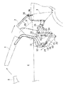
図1は、本発明の実施形態に係わるルーフ格納型車両の外観を示す側面図である。図において、ルーフ格納型車両100は、実質的に変形しない部材で構成されたルーフを、フロントウインドフレーム5の後方に位置したセンタールーフ部1、その後方に位置したリアルーフ部2、およびバックウインド部3に分割し、格納機構により車体内部のルーフ格納部8に格納してオープントップ状態とすることが可能である。
Hereinafter, embodiments of the present invention will be described in detail with reference to the drawings.
FIG. 1 is a side view showing an appearance of a roof retractable vehicle according to an embodiment of the present invention. In the figure, a roof
ルーフ格納部8は、後部座席7とその後方に位置した荷室4との間に画成されており、ルーフ格納部8と荷室4とはキャビンバックパネル81によって仕切られ、ルーフ格納部8の下面はフロアパネル61によって画成されている。ルーフ閉鎖状態で車室6内に位置したルーフ格納部8の上部には、後述するトノカバー9が開閉可能に設けられ、ルーフ格納時および展張時に開いてルーフ各部を出入可能にするとともに、ルーフ閉鎖状態およびルーフ開放状態ではルーフ格納部8を閉鎖可能に構成されている。
The
センタールーフ部1、リアルーフ部2、バックウインド部3の格納機構は、ルーフ格納部8の両側部に配置された共通のベースプレート10,10に左右一対で設けられている。センタールーフ部1は、ベースプレート10に回動可能に軸支されたコントロールアーム11およびドライブアーム12の先端部に回動可能に連結され、これらセンタールーフ部1、コントロールアーム11、ドライブアーム12、ベースプレート10は、4節リンク機構を構成している。
The storage mechanism of the
ドライブアーム12の他端部には、リンクアーム13を介して流体圧シリンダ等からなるアクチュエータ15が連結され、アクチュエータ15はベースプレート10に揺動可能に支持されている。リンクアーム13にはリンクコントロールアーム14が連結され、これらリンクアーム13、リンクコントロールアーム14、レバー12cは4節リンク機構を構成しており、アクチュエータ15の直線的な往復動がドライブアーム12の広い揺動角の範囲で効率良く伝達されるようにしている。
The other end of the
リアルーフ部2の下端部にはリアルーフアーム21が固定され、リアルーフアーム21はベースプレート10に揺動可能に軸支されている。リアルーフアーム21にはアクチュエータ22が連結され、アクチュエータ22はベースプレート10に揺動可能に支持されている。なお、アクチュエータ22を設ける代わりに、リアルーフアーム21とセンタールーフ部1のドライブアーム12とをリンク機構を介して連結し、リアルーフアーム21をドライブアーム12に連動させるようにしても良い。
A
バックウインド部3の下端部にはバックウインドアーム31が固定され、バックウインドアーム31はベースプレート10に揺動可能に軸支されている。また、バックウインド部3の上端部には、リアルーフ部2側に延出したアッパーアーム36が固定され、アッパーアーム36の先端部にはローラ35が回動自在に設けられている。ローラ35は、リアルーフ2に固定されたガイドレール25に沿って移動可能に係合しており、リアルーフ部2の揺動に応じてバックウインド部3が確定的に揺動するようになっている。なお、バックウインドアーム31には、バックウインド部3の重量を封入ガスの圧力で平衡させるガス圧式バランサー33が揺動可能に軸支され、バランサー33の先端はベースプレート10に連結されている。
A
以上のように構成されたセンタールーフ部1、リアルーフ部2、バックウインド部3の開閉動作について、図2〜4を参照しながら説明する。
Opening and closing operations of the
図2に示すルーフ閉鎖状態では、センタールーフ部1は図示しないロック機構によりフロントウインドフレーム5にロックされ、アクチュエータ15のロッドは短縮され、アクチュエータ22のロッドは伸長されている。また、バランサー33のロッドも伸長されている。ローラ35は、ガイドレール25の車両前後方向の後端部に位置している。
2, the
この状態から、図3に示すように、アクチュエータ22のロッドを短縮させ、リアルーフアーム21とともにリアルーフ部2を車両後方へ揺動させると、リアルーフ部2にローラ35およびガイドレール25を介して連結されているバックウインド部3も車両後方へ揺動する。続いて、アクチュエータ15のロッドを伸長してドライブアーム12を揺動させ、センタールーフ部1を車両後方へ揺動させる。
From this state, as shown in FIG. 3, when the rod of the
バックウインド部3が格納位置に到達すると、リアルーフ部2の揺動半径に比べてバックウインド部3の揺動半径が短いことにより、リアルーフ部2の更なる揺動に対してバックウインド部3が同じ位置関係を維持できなくなり、ガイドレール25に沿ってローラ35が移動し始め、バックウインド部3がリアルーフ部2の前方にずれ、リアルーフ部2はバックウインド部3の後方をさらに下方へ揺動する。最終的に、リアルーフ部2、バックウインド部3の格納状態では、ローラ35はガイドレール25の端部に到達する。
When the
アクチュエータ15のロッドをさらに伸長すると、図4に示すように、センタールーフ部1は、バックウインド部3の前方に格納される。このようなオープントップ状態では、最後部の座席7と車両後部の荷室4との間に形成されたルーフ格納部8に、車両後方からリアルーフ部2、バックウインド部3、センタールーフ部1の順に、ほぼ起立状態で重なり合って格納される。ルーフ閉鎖状態に戻す場合は、上記と逆の操作により行う。また、上記格納状態からリアルーフ部2とバックウインド部3のみを元位置に復帰させてタルガトップ状態とすることも可能である。
When the rod of the
次に、ルーフ格納部8の上部を開閉するためのトノカバー9とその開閉機構について、図5〜図11を参照しながら詳細に説明する。
Next, the
図5〜図7は、車両100のルーフを格納しトノカバー9を閉鎖した状態を示す平面図および斜視図である。図において、トノカバー9は、後部座席7とその後方に位置した荷室4との間に拡がるルーフ格納部8の上部に開閉可能に設けられ、閉鎖状態では後部座席7のシートバック71上端とほぼ同じ高さ位置に略水平に位置している。
5 to 7 are a plan view and a perspective view showing a state where the roof of the
後部座席7の後方から側方にかけての部分には、後部座席7を後側から取り囲むようにフレーム構造体62が配設され、該フレーム構造体62の表面はトリム63(内装材)で被覆されており、このトリム63によって、ルーフ格納部8上部開口の車両前方側の縁部が画成されている。実施形態では、トリム63上面の車両後方側の縁部には段部63a(図5、図9参照)が形成されており、トノカバー9の前縁部(車両前方側の縁部)は、閉鎖状態で段部63aに進入して位置している。
A frame structure 62 is disposed in a portion from the rear side to the side of the
一方、ルーフ格納部8上部開口の車両後方側から側方にかけての縁部は、トランクリッドの車両前方側縁端部に沿って延設されたガーニッシュ41、および、車体側部パネル上端に延設されたガーニッシュ66によって画成されており、トノカバー9の後縁部(車両後方側から側方にかけての縁部)は、閉鎖状態で、ガーニッシュ41、66に装着された図示しないシール部材に接合している。
On the other hand, the edge from the vehicle rear side to the side of the upper opening of the
トノカバー9は、車幅方向の中央に位置した中央部材9Aと、その両側に隣接した各側部材(9B、9C)の3つの部分で構成され、実施形態では、各側部材は、さらに各2つの側部材9B、9Cに分割され、左右両側合わせて5つの部分で構成されている。後部座席7の後方に車幅方向に延在する中央部材9Aに対して、その両側に位置した各側部材9B、9Cは、後部座席7の側方に回り込むように車両前方側に延出している。なお、一番外側の側部材9C、9Cの車両前方側の縁端部とトリム63との間には、図2に示したルーフ閉鎖状態で上方に揺動しているセンタールーフ部1のコントロールアーム11とドライブアーム12とを挿通させる開口部67、67が画成されている。
The
トノカバー9は、図7および図8に示すように、中央部材9Aが車両前後方向に離間した2位置において前側リンク91と後側リンク92を介してフレーム構造体62に揺動可能に連結され、前後各側のリンク91、92と中央部材9Aとが、車体側(フレーム構造体62)を固定節とする4節リンク機構を構成している。そして、中央部材9Aの両側に側部材9B、9Bが折曲可能に連結され、これら側部材9B、9Bの他側に、それぞれ側部材9C、9Cが折曲可能に連結されることで、全体が車両前後方向に移動可能であるとともに、各側部材9B、9Cが車幅方向中央側へ引込み可能となっている。各側部材9B、9Cの折曲機構については後述する。
As shown in FIGS. 7 and 8, the
前側リンク91の一端91aは、後部座席7の側方においてフレーム構造体62に回動自在に連結され、前側リンク91の他端91bは、トノカバー中央部材9Aの前端部の裏側に回動自在に連結されている。左右各側の前側リンク91は、他端91bにおいて車幅方向に延在する回動軸を成して一体に連結された一部材で構成されている。
One
後側リンク92の一端92aは、後部座席7の後方においてフレーム構造体62に回動自在に連結され、後側リンク92の他端92bは、トノカバー中央部材9Aの中央部の裏側に回動自在に連結されている。後側リンク92も前側リンク91と同様に左右各側の他端92bにおいて車幅方向に延在する回動軸を成して一体に連結された一部材で構成されているが、前側リンク91に比較して左右各側の間隔が狭く、車幅方向の中央付近に配置されている。
One
前側リンク91の車体側回動端91aは、図8に示すように、ルーフ格納部8の上部開口とほぼ同じ高さ位置に配設され、前側リンク91が、トノカバー9の閉鎖状態で殆ど水平に近い姿勢に倒伏されるのに対し、後側リンク92の車体側回動端92aは、後述する理由により前側リンク91の回動端91aより下方に配設されている。
As shown in FIG. 8, the vehicle body side rotation end 91 a of the
そこで、後側リンク92は、中間部において屈曲され、トノカバー9の閉鎖状態で、車体側回動端92aから中間部に向けて斜めに立ち上がる部分と、中間部から他端92bに至る、トノカバー9の裏面に沿って水平に倒伏される部分とで構成されており、これにより、後側リンク92のルーフ格納部8への突出を抑制している。特に、前側リンク91に比較して車両後方側に位置し、格納されたルーフ各部に近接する後側リンク92の左右各側の間隔を狭くし、車幅方向の中央付近に配置した構成により、ルーフ各部の格納姿勢(ルーフ各部の湾曲形状)により生じる空間を有効に利用でき、格納空間を小さく形成できる利点がある。
Therefore, the
上記のように前後各側のリンク91、92を介して揺動可能に支持されているトノカバー中央部材9Aは、前側リンク91に連結された駆動手段により往復揺動される。駆動手段は、図8に示すように、駆動源であるモータ93、該モータ93の出力軸の回転を駆動軸93aに伝達するウオームギヤ等の減速歯車列(図示せず)、該駆動軸93aに固定された駆動アーム94、該駆動アーム94の先端部と前側リンク91の腕部91cとを回動可能に連結する駆動リンク95から構成されている。
As described above, the tonneau cover
腕部91cは前側リンク91の車幅方向に延在する回動軸(91b)の中央部に剛接合され、前側リンク91と一体に揺動可能であり、図8に2点鎖線で示されるトノカバー9の閉鎖状態では、前記回動軸(91b)から車両前方側に突出している。なお、駆動源としては、電動モータ以外の回動型アクチュエータや、流体圧シリンダ等の直動型アクチュエータを使用でき、直動型アクチュエータを使用する場合には、その出力ロッドを前側リンク91の腕部91cまたは駆動アーム94に連結すれば良い。
The
前側リンク91の駆動手段を構成する上記モータ93は、前後各側のリンク91、92を揺動可能に支持するフレーム構造体62に固定されている。このフレーム構造体62は、図7に示すように、後部座席7の両側方の車体フロアに固着されその部分から立ち上がる左右一対の側部フレーム62B、62Bと、それらの後上部に剛接合され後部座席7の後側に車幅方向に延在する車幅方向フレーム62Aとで構成され、全体として門型の剛構造をなし、平面視においては車両前方側に開放された略コ字状に形成されている。
The
また、車幅方向フレーム62Aの、後部座席7の左右の座席に対応した位置には、それぞれ乗員保護用のロールバー65、65が剛接合されており、ロールバー65、65の基部はトリム63で覆われ、逆U字状をなす上半部がトリム63を越えて上方に突出している。そして、左右のロールバー65、65の中間部には、トリム63の上面を構成するリッド64が開閉可能に設けられている。リッド64は、その車両前方側縁部の軸を中心としてトリム63またはフレーム構造体62に揺動可能に支持され、図示しない付勢部材(スプリング)によって閉鎖方向に付勢されている。
Further, occupant
上記のように構成されたフレーム構造体62の、車幅方向フレーム62Aの中央部に、モータ93(および減速歯車列のギヤケース)が固定され、該車幅方向フレーム62Aの車両後方側の面に、後側リンク92の車体側回動端92aが揺動可能に軸支されている。また、前側リンク91の車体側回動端91aは、各側部フレーム62B、62Bの上端部に揺動可能に軸支されている。すなわち、トノカバー中央部材9Aを揺動可能に支持する前後各側のリンク91、92と、駆動手段(93)とが、共に剛性の高いフレーム構造体62に設けられている。さらに、前側リンク91の車幅方向の中央部に駆動力を伝達することで、該駆動力をトノカバー9全体にバランスよく作用させることができ、前後各側のリンク91、92およびトノカバー9のねじれ等の問題を回避できる。
The motor 93 (and the gear case of the reduction gear train) is fixed to the center of the vehicle
次に、上記トノカバー9の退避動作について図8を参照しながら説明する。
Next, the retracting operation of the
トノカバー9(中央部材9A)は、図中2点鎖線で示される閉鎖位置では、ルーフ格納部8の上部にほぼ水平姿勢で配置され、ルーフ格納部8の上部開口を閉鎖している。また、前後各側のリンク91、92は車体側回動端91a、92aから車両後方側に倒伏され、駆動アーム94は後下方に位置し、リッド64は閉じている。
The tonneau cover 9 (
この状態から、モータ93を作動させ、駆動アーム94を上方に向けて約90度揺動させると、該駆動アーム94に駆動リンク95を介して連結された前側リンク91の腕部91cが押し上げられ、該前側リンク91が上方に揺動され、図中91′で示されるような略直立状態となる。これとともに、前側リンク91に中央部材9Aを介して連結されている後側リンク92が、前方に、図中92′で示される位置まで揺動する。
From this state, when the
このような前後各側のリンク91、92の動作により、トノカバー9は、その前端が閉鎖位置から上方かつ前方に移動すると同時に後端が前方に移動し、図8に実線9′で示されるように、ルーフ格納部8の車両前方側に傾斜姿勢で退避し、ルーフ格納部8の上部が開放される。この際、リッド64は前側リンク91の腕部91cで押し上げられて開放され、その開放された部分に、後側リンク92が進入する。トノカバー9を元の閉鎖位置に戻す場合は、モータ93を逆回転させる。
By such operation of the
前側リンク91は、トノカバーの閉鎖位置と開放位置との間で、側面視において略水平状態から略垂直状態までの約90度の揺動範囲を利用しており、トノカバー9の前端を上方に効率良く移動させることができる。後側リンク92も同様に約85度揺動するが、揺動範囲が異なっている。後側リンク92の車体側回動端92aは前側リンク91の車体側回動端91aよりも下方に位置し、トノカバーの閉鎖位置と開放位置との間で、側面視において、上方に約25度傾斜した状態から、垂直状態を越えて前方に約20度傾斜した状態までの揺動範囲を利用しており、トノカバー9の後端を低位置に維持した状態で専ら前方に移動させ、ルーフ格納部8の上部開口から退避させる。
The
このように、前後各側リンク91、92で異なる揺動範囲を利用し、トノカバー9をルーフ各部の移動軌跡に沿った傾斜姿勢で退避させることにより、トノカバー9の後端を完全に退避させながらも、トノカバー9の前端の前方への移動が小さく、後部座席7側への突出と、それに伴う乗員の頭部への干渉が抑制され、ルーフの移動軌跡から効率的に退避させることができる。
In this way, by using the swing ranges different for the front and rear side links 91 and 92 and retracting the
次に、トノカバー9の中央部材9Aに対する各側部材9B、9Cの折曲機構について説明する。
Next, the bending mechanism of each
トノカバー9の中央部材9Aと、その両側に隣接する側部材9B、9Bとは、図5、6に示されるように、後部座席7の側端付近において、ほぼ車両前後方向に延在する直線状の分割線によって分割され、その部分において折曲可能に連結されている。側部材9B、9Bは、後部座席7の側方に回り込むようにして、中央部材9Aから斜め前方に延出しており、実施形態の車両では、側部材9B、9Bは、前記分割位置とトノカバー9の側端との中間付近において、車両後外方に向かう斜め方向の分割線によって、該側部材9B、9Bと側部材9C、9Cとに更に分割され、その分割部分において折曲可能に連結されている。なお、以上述べた「分割」には、インテグラルヒンジ等による非分割の屈曲可能な連結も包含される。
The
図9(a)は、側部材9Bと側部材9Cとの連結部分を示す車幅方向の断面図であり、(b)はその紙面厚さ方向にずれた断面の拡大図である。各図において、側部材9Bと側部材9Cのとは、それらの端縁部に一体に形成したヒンジ部96により、回動範囲が規制された状態で回動可能に連結され、ヒンジ部96の軸96aに装着されたスプリング97によって、互いに折曲を伸展させる方向に付勢されている。
FIG. 9A is a cross-sectional view in the vehicle width direction showing a connecting portion between the
即ち、図9(b)に示すように、側部材9Bと側部材9Cの各ヒンジ部には、それらが、平坦なトノカバー上面を形成する最大伸展状態で相互に当接するストッパ面96b、96cと、最大折曲状態で相互に当接するストッパ面96d、96eが形成され、ヒンジ部96の回動が角δの範囲に規制されている。さらに、図9(a)に示すように、スプリング97のそれぞれの端部が、側部材9B、側部材9Cの裏面に当接することによって、側部材9B、側部材9Cはストッパ面96b、96cが当接する方向に相互に付勢されている。なお、トノカバー9の中央部材9Aと側部材9B、9Bとの連結部分も同様の構成であるため、その説明は省略する。
That is, as shown in FIG. 9B, the hinge portions of the
さらに、図9、10に示すように、トノカバー9の外側の側部材9C、9Cの裏面と、前側リンク91の各回動端91a、91bの中間部分とは、連結部材98、98によってそれぞれ連結され、前側リンク91の揺動、すなわち、トノカバー9の格納動作に連動して、側部材9Bが中央部材9Aに対して折曲されると同時に側部材9Cが側部材9Bに対して折曲され、各側部材9B、9Cが車幅方向中央側へ引込まれるように構成されている。
Further, as shown in FIGS. 9 and 10, the back surfaces of the
連結部材98としては、可撓性を有さないロッド等も使用可能であるが、実施形態の連結部材98には引張力のみが作用するので、可撓性を有する線状、紐状あるいは帯状の部材、リンクやチェーンなどの折曲可能な部材が好適である。さらに、図示例では、連結部材98の中間部分にテンションスプリングが設けられ、伸縮性を有している。連結部材98が伸縮性を有することにより、ヒンジ部96における回動規制との調整が不要となる利点がある。なお、連結部材98は、全長に亘ってテンションスプリングで構成されていても良いし、また、テンションスプリングの代わりにゴムバンドを用いることもできる。また、内外のヒンジ部におけるスプリング97のバネ定数を異ならせることにより、各側部材9B、9Cの折曲時期を異ならせることもできる。
As the connecting
次に、上記のように構成されたトノカバー折曲機構の動作について、図6〜図11を参照しながら説明する。 Next, the operation of the tonneau cover bending mechanism configured as described above will be described with reference to FIGS.
トノカバー9がルーフ格納部8の上部を閉鎖した状態では、図7および図8に示されるように、前側リンク91は、トノカバー9の裏面に沿ってほぼ水平に倒伏され、前側リンク91と側部材9Cとは近接している。このため、前側リンク91と側部材9Cとを連結する連結部材98は弛緩し、トノカバー9の中央部材9A、各側部材9B、9Cは、ヒンジ部96に設けたスプリング97の付勢により最大伸展状態に伸展されている。
In a state in which the
この状態から、先述した駆動手段により前側リンク91が上方に揺動を開始すると、前側リンク91とトノカバー9が相対回転を始め、前側リンク91と側部材9Cとが離反し始める。すると、図10、11に示すように、連結部材98が緊張され、該連結部材98によって側部材9Cが引張されることにより、該側部材9C、9Bがスプリング97の付勢力に抗して各ヒンジ部分において回動範囲の規制位置まで折曲される。各側部材9C、9Bのヒンジ部分の回動が規制位置に達した後には、側部材9Cはそれ以上屈曲できなくなり、テンションスプリングが伸びてオーバーストロークを吸収することで、トノカバー9の各ヒンジ部96に過大な力が作用することを防止できる。
From this state, when the
この時、側部材9Cと側部材9Bとの連結部分では、ヒンジ部96の軸96aが車両後外方に向けて斜めに配向されているので、トノカバー9を閉鎖位置から退避させた傾斜姿勢において、トノカバー9の上端側の幅が狭くなり、ルーフの内面形状に沿って、少ない移動量でルーフの移動軌跡から退避させることができる。
At this time, in the connecting portion between the
また、車両側部に配設されるルーフ格納機構の揺動範囲を確保すべく、トノカバー9の各側部材9B、9Cを中央部材9Aに対して車両前方に延出させているが、上記傾斜姿勢では、各側部材9B、9Cの折曲によって側部材9Cの先端位置が下がり、ルーフ移動軌跡との干渉を回避できる。その際、側部材9Cの車両前方側が下方に移動するのに対し、側部材9Cの車両後方側はヒンジ部96の軸96aに近く、降下量が小さくなるため、トノカバー9の開放動作の初期において、まだ中央部材9Aの傾斜が小さい状態でも、側部材9Cの折曲を開始することが可能になる。なお、折曲された各側部材9B、9Cは、トノカバー9を閉鎖位置に復帰させる動作により、前側リンク91と側部材9Cとが接近して連結部材98が弛緩するのに伴い、スプリング97の付勢力で伸展される。
Further, in order to secure a swing range of the roof retracting mechanism disposed on the side of the vehicle, the
上記実施形態においては、トノカバー9が中央部材9Aと各側部材9B、9Cの5つの部分に分割され、それぞれ折曲可能に連結された場合を示したが、ルーフの分割形状や格納形式によっては、トノカバーが、中央部材と各側部材の3つの部分で構成される場合もある。また、退避時に室内空間に影響があるが、ドア上方の開口部を利用することにより、トノカバーを分割せずに1つの部材で構成することも可能である。
In the above embodiment, the
トノカバー9の中央部材9A、および各側部材9B、9Cの材質は、特に限定されるものではなく、可逆的に変形しない硬質材料や、可逆的に変形しうる軟質材料、可撓性弾性材料などを適宜用いることができるが、トノカバー9の中央部材9A、および各側部材9B、9Cの、それぞれの周縁部9eは、エラストマーなどの軟質材を使用すると、ルーフ閉鎖時における各ヒンジ部分96の変位が小さくなり、外観上好ましい。この場合、前記周縁部分9e以外の主部9dには、硬質かつ軽量な樹脂材を使用し、トノカバー9の移動時における変形を防止することが好適である。
The material of the
また、上記実施形態においては、トノカバー9の各側部材9B、9Cが、中央部材9Aに対してヒンジ部96で折曲可能に連結され、すなわち、分割線に沿った軸回りに回動可能に連結される場合を示したが、各側部材が中央部材に対してトノカバーの平面に垂直な軸回りに回動可能に連結されるか、各側部材が中央部材に摺動可能に連結することにより、各側部材を中央部材の下側または内部に引き込み可能であっても良い。
Moreover, in the said embodiment, each
また、上記実施形態においては、トノカバー9の中央部材9Aが、4節リンク機構を構成する前側リンク91と後側リンク92とで揺動可能に連結されることにより、トノカバー9の前端が閉鎖位置から前方かつ上方に移動するとともに、トノカバー9の後端が前方に移動する動作が確定され、トノカバー9が傾斜姿勢で退避される場合を示したが、本発明はこれに限定されるものではなく、同様の確定動作が可能な他の機構によって実施される場合も包含する。例えば、前側リンク91およびモータ93の代わりに、車体側に揺動可能に連結された直動型アクチュエータを備え、該直動型アクチュエータの出力ロッドをトノカバー9の前端に回動可能に連結し、該出力ロッドを進退動作させることにより、同様の確定動作を実現できる。
Further, in the above embodiment, the
また、トノカバー9の駆動手段(93)を、フレーム構造体62の中央部に設ける代わりに、該フレーム構造体62の車幅方向両側部(車幅方向フレーム62Aの両側部、または各側部フレーム62B、62B)に設けるようにしても良い。その場合、各側の駆動手段として、中央部に設ける場合と同様にモータとリンク機構を設ける構成の他に、前側リンク91(または後側リンク92)の回動軸支部(91aまたは92a)をギヤとモータで駆動する構成、あるいは、各側にそれぞれ流体圧アクチュエータを設ける構成などを採用でき、各側の動力源が別であれば同期させる必要は生じるものの、座席中央の空間的な制約が少なく、各側の回動軸支部またはその近傍に確実に動力を伝達できる利点がある。
Further, instead of providing the driving means (93) of the
また、上記実施形態においては、後部座席7の後方の格納部8に、ルーフを3分割して格納する場合について述べたが、本発明はこれに限定されるものではなく、本発明のルーフ格納型車両は、他のルーフ格納方式、例えば、ルーフを2分割して車体内部に格納するハードトップタイプの車両や、ルーフを折畳んで格納するソフトトップタイプの車両などとしても実施可能である。
Moreover, in the said embodiment, although the case where the roof was divided and stored in the
以上、本発明の実施の形態について述べたが、本発明は上記実施形態に限定されるものではなく、本発明の技術的思想に基づいて各種の変形および変更が可能である。 Although the embodiments of the present invention have been described above, the present invention is not limited to the above-described embodiments, and various modifications and changes can be made based on the technical idea of the present invention.
1 センタールーフ部
2 リアルーフ部
3 バックウインド部
4 荷室
5 フロントウインドフレーム
6 車室
7 後部座席
8 ルーフ格納部
9 トノカバー
9A 中央部材
9B、9C 側部材
11 コントロールアーム
12 ドライブアーム
21 リアルーフアーム
25 ガイドレール
31 バックウインドアーム
35 ローラ
36 アッパーアーム
41、66 ガーニッシュ
62 フレーム構造体
63 トリム
64 リッド
91 前側リンク
92 後側リンク
93 モータ(駆動源)
94 駆動アーム
95 駆動リンク
96 ヒンジ部
96b、96c ストッパ面(規制手段)
97 スプリング(付勢部材)
98 連結部材
100 ルーフ格納型車両
DESCRIPTION OF
94
97 Spring (Biasing member)
98 Connecting
Claims (8)
前記トノカバーが車体側に対して機構的に連結され、前記トノカバーの前端が閉鎖位置から前方かつ上方に移動するとともに、前記トノカバーの後端が前方に移動する動作によって、前記トノカバーが前記閉鎖位置から車両前方側に傾斜姿勢で退避し、前記ルーフ格納部の上部が開放されるように構成されていることを特徴とするルーフ格納型車両。 In a roof retractable vehicle comprising: a roof storage portion defined behind a seat; a roof storage mechanism for storing a roof in the roof storage portion; and a tonneau cover for opening and closing an upper portion of the roof storage portion. ,
The tonneau cover is mechanically connected to the vehicle body side, the front end of the tonneau cover moves forward and upward from the closed position, and the rear end of the tonneau cover moves forward to move the tonneau cover from the closed position. A roof retractable vehicle, wherein the roof retractable vehicle is configured to retract in an inclined posture toward the front side of the vehicle and to open an upper portion of the roof storage portion.
Priority Applications (3)
| Application Number | Priority Date | Filing Date | Title |
|---|---|---|---|
| JP2006328312A JP2008137601A (en) | 2006-12-05 | 2006-12-05 | Roof storage type vehicle |
| DE102007058223.6A DE102007058223B4 (en) | 2006-12-05 | 2007-12-03 | Cabriolet |
| US11/999,146 US7828362B2 (en) | 2006-12-05 | 2007-12-04 | Roof retractable type vehicle |
Applications Claiming Priority (1)
| Application Number | Priority Date | Filing Date | Title |
|---|---|---|---|
| JP2006328312A JP2008137601A (en) | 2006-12-05 | 2006-12-05 | Roof storage type vehicle |
Publications (1)
| Publication Number | Publication Date |
|---|---|
| JP2008137601A true JP2008137601A (en) | 2008-06-19 |
Family
ID=39363395
Family Applications (1)
| Application Number | Title | Priority Date | Filing Date |
|---|---|---|---|
| JP2006328312A Pending JP2008137601A (en) | 2006-12-05 | 2006-12-05 | Roof storage type vehicle |
Country Status (3)
| Country | Link |
|---|---|
| US (1) | US7828362B2 (en) |
| JP (1) | JP2008137601A (en) |
| DE (1) | DE102007058223B4 (en) |
Families Citing this family (5)
| Publication number | Priority date | Publication date | Assignee | Title |
|---|---|---|---|---|
| JP2008537518A (en) * | 2005-02-03 | 2008-09-18 | ツェーテーエス ファーツォイク ダッハジステーム ゲーエムベーハー | Retractable vehicle roof and combined package shelf and tonneau |
| DE102005057651B4 (en) * | 2005-12-01 | 2008-02-14 | Magna Car Top Systems Gmbh | Vehicle with cover assembly |
| JP2012206675A (en) * | 2011-03-30 | 2012-10-25 | Tokai Rika Co Ltd | Tonneau cover device |
| ITBO20110479A1 (en) * | 2011-08-01 | 2013-02-02 | Ferrari Spa | CAR WITH OPENING ROOF PROVIDED WITH SEALING GASKETS |
| US8991895B2 (en) * | 2013-03-14 | 2015-03-31 | GM Global Technology Operations LLC | Door system |
Family Cites Families (16)
| Publication number | Priority date | Publication date | Assignee | Title |
|---|---|---|---|---|
| JPH0247050Y2 (en) | 1986-10-28 | 1990-12-11 | ||
| JP2795433B2 (en) | 1987-12-08 | 1998-09-10 | 株式会社オーテックジャパン | Compatible car hood storage device |
| JP3349231B2 (en) | 1993-12-16 | 2002-11-20 | マツダ株式会社 | Convertible car body structure |
| DE19749552C2 (en) * | 1997-11-10 | 1999-12-09 | Cts Fahrzeug Dachsysteme Gmbh | Cabriolet vehicle |
| JP2000103288A (en) | 1998-09-29 | 2000-04-11 | Toyota Motor Corp | Housing structure of package tray |
| DE10001958B4 (en) | 2000-01-18 | 2005-06-09 | Webasto Ag | Convertible vehicle roof |
| FR2834951B1 (en) * | 2002-01-21 | 2004-06-04 | France Design | REAR SHELF FOR MOTOR VEHICLE WITH FOLDABLE ROOF |
| DE10222189B4 (en) * | 2002-05-18 | 2008-09-04 | Daimler Ag | Covering device for a convertible top compartment of a convertible vehicle |
| FR2851509A1 (en) * | 2003-02-21 | 2004-08-27 | Renault Sa | Retractable roof for vehicle, has panel moved by guiding unit, where controlled movement of roof between its closed and retracted position generates movement of structure of rear cover and part of interior cab |
| JP4198500B2 (en) * | 2003-03-25 | 2008-12-17 | ベバスト ジャパン株式会社 | Traveling vehicle |
| FR2853868B1 (en) * | 2003-04-15 | 2005-06-24 | France Design | RETRACTABLE REAR RANGE SYSTEM FOR A DISABLED VEHICLE WITH A FOLDING ROOF |
| JP2005231460A (en) * | 2004-02-18 | 2005-09-02 | Toyo Seat Co Ltd | Tonneau cover structure of convertible top vehicle |
| JP2005254912A (en) * | 2004-03-10 | 2005-09-22 | Toyo Seat Co Ltd | Vehicular roof cover device |
| JP4478523B2 (en) * | 2004-07-02 | 2010-06-09 | 株式会社東洋シート | Convertible top car tonneau cover structure |
| DE102005057651B4 (en) * | 2005-12-01 | 2008-02-14 | Magna Car Top Systems Gmbh | Vehicle with cover assembly |
| DE102006046345B4 (en) * | 2006-09-28 | 2014-05-15 | Webasto Ag | Cover flap of a convertible |
-
2006
- 2006-12-05 JP JP2006328312A patent/JP2008137601A/en active Pending
-
2007
- 2007-12-03 DE DE102007058223.6A patent/DE102007058223B4/en not_active Expired - Fee Related
- 2007-12-04 US US11/999,146 patent/US7828362B2/en not_active Expired - Fee Related
Also Published As
| Publication number | Publication date |
|---|---|
| US20080129076A1 (en) | 2008-06-05 |
| US7828362B2 (en) | 2010-11-09 |
| DE102007058223B4 (en) | 2014-02-06 |
| DE102007058223A1 (en) | 2008-06-12 |
Similar Documents
| Publication | Publication Date | Title |
|---|---|---|
| JP3771877B2 (en) | Cover device for roof mechanism storage | |
| EP2006139B1 (en) | Retractable roof and vehicle with the same | |
| JP4790465B2 (en) | Retractable roof and vehicle equipped with the same | |
| CN105459768B (en) | The rear structure of vehicle body of vehicle | |
| US7163255B2 (en) | Folding convertible top with integral boot | |
| JP2008137601A (en) | Roof storage type vehicle | |
| EP1549519B1 (en) | Decklid mechanism for vehicle with retractable top | |
| US6688669B2 (en) | Motor vehicle having a folding roof which can be opened | |
| JP3578441B2 (en) | Body reinforcement structure for cabriolet vehicles | |
| JP4958479B2 (en) | Retractable roof and vehicle equipped with the same | |
| WO2007114148A1 (en) | Retractable roof and vehicle with the same | |
| JP5028347B2 (en) | Drive structure for convertible top for vehicles | |
| JP5159472B2 (en) | Drive structure for convertible top for vehicles | |
| JP5948911B2 (en) | Opening and closing device for vehicle roof | |
| JPS6226118A (en) | On-off roof structure in automobile | |
| JP4933346B2 (en) | Top cover of garbage truck | |
| JP5605154B2 (en) | Vehicle movable roof structure | |
| JP5400509B2 (en) | Convertible top drive | |
| JP2007022166A (en) | Tonneau cover device | |
| JP2012086614A (en) | Movable roof structure of vehicle | |
| JPH0262408B2 (en) | ||
| JP2012086612A (en) | Movable roof structure of vehicle | |
| JP4022956B2 (en) | Openable / closable roof structure for vehicles | |
| JP5691376B2 (en) | Vehicle movable roof structure | |
| JP2007302145A (en) | Rear part luggage compartment structure of vehicle |