EP1549519B1 - Decklid mechanism for vehicle with retractable top - Google Patents
Decklid mechanism for vehicle with retractable top Download PDFInfo
- Publication number
- EP1549519B1 EP1549519B1 EP03755489.6A EP03755489A EP1549519B1 EP 1549519 B1 EP1549519 B1 EP 1549519B1 EP 03755489 A EP03755489 A EP 03755489A EP 1549519 B1 EP1549519 B1 EP 1549519B1
- Authority
- EP
- European Patent Office
- Prior art keywords
- decklid
- rearward
- luggage
- linkage member
- actuator
- Prior art date
- Legal status (The legal status is an assumption and is not a legal conclusion. Google has not performed a legal analysis and makes no representation as to the accuracy of the status listed.)
- Expired - Lifetime
Links
- 230000007246 mechanism Effects 0.000 title claims description 17
- 230000000717 retained effect Effects 0.000 description 3
- 230000000712 assembly Effects 0.000 description 2
- 238000000429 assembly Methods 0.000 description 2
- PEDCQBHIVMGVHV-UHFFFAOYSA-N Glycerine Chemical compound OCC(O)CO PEDCQBHIVMGVHV-UHFFFAOYSA-N 0.000 description 1
Images


Classifications
-
- B—PERFORMING OPERATIONS; TRANSPORTING
- B60—VEHICLES IN GENERAL
- B60J—WINDOWS, WINDSCREENS, NON-FIXED ROOFS, DOORS, OR SIMILAR DEVICES FOR VEHICLES; REMOVABLE EXTERNAL PROTECTIVE COVERINGS SPECIALLY ADAPTED FOR VEHICLES
- B60J7/00—Non-fixed roofs; Roofs with movable panels, e.g. rotary sunroofs
- B60J7/20—Vehicle storage compartments for roof parts or for collapsible flexible tops
- B60J7/205—Vehicle storage compartments for roof parts or for collapsible flexible tops where the boot lid opens in rearward direction to receive the roof and in forward direction to receive luggage
Definitions
- the present invention relates generally to vehicles with retractable roof structures and, more specifically, to a system for articulating a vehicle decklid to either a top receiving position or a luggage receiving position.
- the vehicle has a decklid that articulates rearwardly to provide a forward facing opening behind the passenger compartment to receive the retracted roof structure.
- the decklid may then be articulated back into the closed position to cover the top stack. This gives the vehicle a finished appearance when the roof is retracted.
- Providing a decklid that will articulate so as to provide a forward-facing opening to receive a retractable roof structure and to also open in a traditional manner to provide a rearward facing opening presents numerous mechanical challenges.
- One approach to providing an articulated decklid that opens both rearwardly and forwardly is to provide a frame which supports the decklid and provides for interconnection with the body.
- the frame typically articulates with the decklid when it moves in one direction and remains stationary when the decklid articulates in the other direction.
- the decklid then latches and pivots with respect to the frame in some positions. Examples of designs using a frame are illustrated in the following patents: U.S. Patent No.'s 5,775,766 , 5,823,606 , 6,010,178 , 6,164,713 , 6,186,577 , 6,270,144 , 6,325,445 , and U.S. Patent Publication No. 2003/0020300 Al. Designs with frames, while functional, add significant cost and weight to vehicle designs.
- the present invention provides an improved articulating decklid system design.
- the decklid system is designed for a vehicle with a body and a retractable roof selectively covering a passenger compartment disposed in the body.
- the vehicle has a luggage storage compartment positioned rearward of the passenger compartment and disposed in the body.
- the luggage compartment has a forward end and a rearward end.
- the system includes a first linkage member having a forward end pivotally interconnected with the vehicle body and a rearward end spaced therefrom.
- the decklid has a forward end and a rearward end. The rearward end is pivotally interconnected with the rearward end of the first linkage member.
- a second linkage assembly has an upper end pivotally interconnected with the decklid and a lower end pivotally interconnected with the first linkage member between the forward and rearward ends.
- the second linkage assembly has a folded position wherein the upper end and the lower end are separated by a first distance and an unfolded position wherein the upper and lower ends are separated by a distance greater than the first distance.
- An actuator is operable to move the second linkage between the folded and unfolded positions.
- the decklid system also includes an actuator.
- the decklid system has a first closed position wherein the rearward ends of the first linkage member and the decklid are adjacent the rearward end of the luggage compartment, the second linkage assembly is in the folded position, and the forward end of the decklid is adjacent the forward end of the luggage compartment.
- the decklid system has a second top receiving position wherein the rearward ends of the first linkage member and the decklid are adjacent the rearward end of the luggage compartment, the second linkage assembly is in the unfolded position, and the forward end of the decklid is spaced from the vehicle body so as to define a generally forward facing opening to receive the retractable roof therethrough.
- the decklid system has a third luggage receiving position wherein the rearward end of the first linkage member and the decklid are spaced from the rearward end of the luggage compartment so as to define a generally rearward facing opening to receive luggage therethrough. In the luggage receiving position, the second linkage assembly is in the unfolded position, and the forward end of the decklid is spaced from the forward end of the luggage compartment.
- a first embodiment of an articulating decklid system is generally shown at 10.
- the system is designed for use with a vehicle having a body 12 and a retractable roof 14 that selectively covers a passenger compartment 16 in the body 12.
- a seatback is shown at 18, to illustrate the rearmost portion of the passenger compartment 16.
- a luggage compartment 20 is defined in the vehicle body rearwardly of the passenger compartment 16.
- the articulating decklid system 10 is designed for use with a retractable roof 14 which, when retracted, is stowed in the luggage compartment 20. Therefore, the decklid system 10 must provide an opening to the luggage compartment 20 for the retractable top 14 to pass through.
- the articulating decklid system 10 includes a first linkage member 22 that has a forward end 24 pivotally interconnected with the vehicle body and a rearward end 26.
- a decklid 30 has a forward end 32 and a rearward end 34. The rearward end 34 of the decklid is pivotally interconnected with the rearward end 26 of the first linkage member 22.
- a second linkage assembly 36 has an upper end 38 pivotally interconnected with the decklid 30 and a lower end 40 pivotally interconnected with the first linkage member 22 between the forward and rearward ends 24 and 26.
- the second linkage assembly 36 has a folded position, shown in Figure 1 , wherein the upper end 38 and lower end 40 are separated by a short distance.
- the second linkage assembly also has an unfolded position, shown in Figures 2-4 , wherein the upper end 38 and lower end 40 are separated by a larger distance. It should be noted that the unfolded positions of Figures 2 and 3 are actually somewhat different, since the decklid 30 is in different positions, and that the upper end 38 and lower end 40 may not be separated by the same distance in both of these unfolded positions. However, they will both be referred to as unfolded positions herein.
- Figure 1 illustrates the decklid system 10 in a closed position. In this position, the rearward ends 26 and 34 of the first linkage member and the decklid are adjacent the rearward end of the luggage compartment 20, the second linkage assembly 36 is in the folded position, and the forward end 32 of the decklid 30 is adjacent the forward end of the luggage compartment. It should be noted that when portions of the decklid system are referred to as being adjacent certain portions of the luggage compartment, they may also be considered to be adjacent corresponding portions of the vehicle body.
- Figure 2 illustrates the decklid system in a luggage receiving position, wherein a rearwardly facing opening is provided to receive luggage into the luggage compartment 20.
- the rearward ends, 26 and 34, of the first linkage member 22 and decklid 30 are spaced from the rearward end of the luggage compartment and the vehicle body.
- the angular movement of the first linkage member 22 also causes the second linkage assembly 36 to move to the unfolded position such that the decklid 30 articulates upwardly and forwardly. This also moves the forward end 32 of the decklid 30 to a position spaced from the forward end of the luggage compartment and the vehicle body.
- Figure 3 illustrates the decklid system in a top receiving position, wherein a forwardly facing opening is provided for the passage of the retractable roof or top therethrough.
- the rearward ends, 26 and 34, of the first linkage member 22 and decklid 30 are adjacent the rearward end of the luggage compartment and the vehicle body.
- the second linkage assembly 36 is moved to the unfolded position, thereby rotating the decklid 30 upwardly and rearwardly. Therefore, the forward end 32 of the decklid 30 is spaced from the forward end of the luggage compartment and from the vehicle body.
- the first linkage member 22 is preferably a generally U-shaped member having a pair of spaced apart side portions 42 and 44.
- the side portions 42 and 44 preferably extend longitudinally along the sides of the luggage compartment 20.
- the side portions 42 and 44 have forward ends that are pivotally connected to the vehicle body and define the forward end of the first linkage member 22.
- the first linkage member 22 also includes a connecting portion 46 that extends transversely between the rearward ends of the side portions 42 and 44. This connecting portion defines the rearward end of the linkage member 22.
- the forward end of the first linkage member 22 is pivotally connected to the vehicle body via brackets, one of which is shown at 48.
- the pivotal interconnection between the first linkage member 22 and the brackets 48 is a simple pivot that defines a pivot axis.
- a more complicated pivoting mechanism such as a four-bar or six-bar linkage, may be provided.
- Such an arrangement is considered a pivotal interconnection for the purposes of the present invention.
- the rearward end 26 of the first linkage member 22 is preferably latched to the vehicle body using a latch 50, shown in Figure 1 .
- This latch 50 may take the form of a traditional trunk latch, or other types of latches may be used.
- One centrally located latch on the connecting portion 46 is preferred, though multiple latches or latches in different positions may be used.
- latches may be provided for connecting the side portions 42 and/or 44 to the vehicle body.
- the decklid 30 is preferably interconnected with the connecting portion 46 of the first linkage member 22 by a simple pivot.
- more complex pivotal interconnections such as four or six-bar linkages, may be used. For purposes of the present invention, these fall within the definition of a pivotal interconnection.
- the simple pivotal connection between the first linkage member 22 and the decklid 30 causes a portion of the rearward end 34 of the decklid to move downwardly as it pivots, as shown in Figure 3 .
- a more complex pivotal interconnection may change this motion profile.
- the location of the pivot may be changed so as to change the motion profile.
- the second linkage assembly 36 may take a variety of forms, but preferably includes an upper link 52 and a lower link 54 that are pivotally interconnected to one another.
- the upper end of the upper link 52 is pivotally interconnected with the decklid 30 adjacent one of its sides, while the lower end of the lower link 54 is pivotally interconnected with the corresponding side portion 42 of the first linkage member 22.
- An actuator 56 has one end pivotally interconnected with the vehicle body, as represented by bracket 48, and the other end pivotally interconnected with the lower link 54 between its upper and lower ends.
- the actuator 56 is preferably a hydraulic linear actuator, but may alternatively be a different type of actuator.
- the actuator 56 has a retracted position, shown in Figures 1 and 2 , and an extended position shown in Figures 3 and 4 .
- the pivotal interconnection between the actuator 56 and the body is preferably forward of the pivotal interconnection between the first linkage member 22 and the vehicle body.
- the actuator 56 is also preferably lockable in its retracted position, such as in Figure 1 . By locking the actuator 56, the decklid 30 is retained in the closed position. Preferably, no other latch is provided between the forward portion of the decklid and the vehicle body.
- the actuator 56 When the decklid system 10 is moved between the closed position of Figure 1 and the luggage receiving position of Figure 2 , the actuator 56 is retained in its retracted position. In this situation, the vehicle body, represented by bracket 48, the actuator 56, the first linkage bar 22, and the lower link 54 form a four-bar linkage. As the first linkage member 22 rotates counter-clockwise, as shown in Figure 2 , this causes the second linkage assembly 36 to move to the unfolded position, thereby moving the forward end 32 of the decklid 30 upwardly and forwardly. This causes the decklid to move up over the vehicle top 14, but also to be move forwardly sufficiently to provide access to the luggage compartment.
- the decklid system 10 may be moved from the closed position of Figure 1 to the top receiving position of Figures 3 and 4 by extending the actuator 56, while maintaining the first linkage member 22 in its original position, in which its rearward end may be latched to the body. This causes the decklid 30 to pivot about the pivotal interconnection between the rearward end 26 of the first linkage member and the rearward end 34 of the decklid 30.
- the second linkage assembly 36 is moved to its unfolded position by the movement of the actuator 56.
- the second linkage assembly previously discussed is illustrated as being on one side of the vehicle.
- an additional linkage assembly referred to as a third linkage assembly, is provided on the other side of the vehicle, as shown at 58.
- a corresponding actuator 60 is also provided. These are preferably identical to the linkage assembly and actuator on the other side of the vehicle.
- a second embodiment of an articulating decklid system is generally shown at 80.
- the system includes a first linkage member 82 with a forward end 84 pivotally interconnected with the vehicle body and a rearward end 86.
- a decklid 88 has a forward end 90 and a rearward end 92.
- the rearward end 92 is preferably pivotally interconnected with the rearward end 86 of the first linkage member 82.
- the first linkage member 82 is preferably U-shaped, and the pivots between the first linkage member and the vehicle body and the decklid are preferably simple pivots.
- An actuator 94 has a first end 96 pivotally interconnected to the decklid 88 and a second end 98 pivotally interconnected to the vehicle body.
- the actuator 94 is preferably a hydraulic actuator, but may also be a different type of linear actuator.
- the actuator 94 has a retracted position, shown in Figure 5 , and an extended position shown in Figure 7 .
- the pivotal interconnection between the forward end 98 of the actuator 94 is preferably forward of the pivotal interconnection between the forward end 84 of the first linkage member 82 and the vehicle body.
- the pivotal interconnection between the first end 96 of the actuator 94 and the decklid 88 is preferably a significant distance rearward. In the illustrated embodiment, the pivotal interconnection is more than halfway back the decklid 88.
- the actuator 94 has both of its ends positioned above the first linkage member 82.
- the actuator 94 is retained in the shortened position and serves as one link in a four-bar linkage. Therefore, the decklid 80 articulates upwardly and forwardly as it rotates counterclockwise as viewed in Figure 6 .
- the actuator 94 is preferably lockable in its retracted position so that it serves as a link.
- the actuator 94 is moved to its extended position, which causes the decklid 88 to rotate clockwise, as shown.
- FIG. 8-10 a third embodiment of an articulating decklid system according to the present invention is generally shown at 100.
- This embodiment is very similar to the Figures of 5-7, except the decklid 102 is two pieces rather than one.
- a rearward piece 104 defines the rear portion of the decklid 102 and a forward portion 106 defines the forward part.
- the portions 104 and 106 are pivotally interconnected to each other and the rearward portion 104 is preferably connected rigidly to the rearward end of the first linkage member 108.
- the forward portion 106 of the decklid pivots relative to the rearward portion 104, rather than the entire decklid pivoting relative to the first linkage member 108.
- the first linkage member 108 and the rear portion 104 of the decklid may be formed together, or rigidly interconnected.
- the rearward portion 104 may form, or replace, the transversely extending connection portion of the member 108.
- the two-piece decklid design of Figures 8-10 may be applied to the first embodiment of the present invention, shown in Figures 1-4 .
- the illustrated actuators may be altered or repositioned.
- the actuators 56 and 60 can be repositioned such that they are behind the second linkage assemblies. In this case, they would be in the extended position when the decklid is closed and in a retracted position when the decklid is in the top receiving position. The actuators could then be locked in the extended position to hold the decklid in the closed position.
- one end of the actuators is connected to the lower link of each of the second linkage assemblies and the other end is connected to the vehicle body. They could alternatively have their second ends connected to the first linkage member 22.
- the actuator would be retracted in both the top receiving and luggage receiving positions to articulate the decklid as shown in the figures.
- the actuators may be locked in the shortened position.
- the actuators may include the ability to be locked in other positions, such as being lockable in both an extended and retracted position, and/or also be lockable in intermediate positions.
- the various linkages illustrated may be reconfigured without departing from the scope of the invention.
- the links forming the second linkage assembly may be shorter or longer, or attached in other positions.
- the other linkage positions and sizes and actuator positions and sizes may also be altered without departing from the scope of the present invention.
Landscapes
- Engineering & Computer Science (AREA)
- Mechanical Engineering (AREA)
- Vehicle Step Arrangements And Article Storage (AREA)
Description
- The present invention relates generally to vehicles with retractable roof structures and, more specifically, to a system for articulating a vehicle decklid to either a top receiving position or a luggage receiving position.
- Most vehicles have rigid roof structures that permanently extend over and cover the passenger compartment. Manufacturers also provide a variety of designs that offer the vehicle operator the opportunity to partially or completely uncover the passenger compartment. Sunroofs and moon roofs are some of the simplest designs, and offer the opportunity to open a portion of the vehicle roof for increased airflow. More complicated designs allow the entire roof structure to be retracted and stored behind the passenger compartment. When retracted, these roof designs form a roof stack to the rear of the passenger compartment. In some designs, a storage area is provided just rearwardly of the passenger compartment and forwardly of the vehicle luggage compartment. A soft or hard cover is sometimes provided for covering the roof stack in the stored position. In other designs, the retracted roof is stored in the vehicle luggage compartment. This approach is especially useful with retractable hard top designs. In one approach, the vehicle has a decklid that articulates rearwardly to provide a forward facing opening behind the passenger compartment to receive the retracted roof structure. The decklid may then be articulated back into the closed position to cover the top stack. This gives the vehicle a finished appearance when the roof is retracted. Most consumers prefer that the trunk also be usable in a traditional manner, wherein the rear end of the decklid opens to provide a rearwardly facing opening to receive luggage or groceries. Providing a decklid that will articulate so as to provide a forward-facing opening to receive a retractable roof structure and to also open in a traditional manner to provide a rearward facing opening presents numerous mechanical challenges.
- One approach to providing an articulated decklid that opens both rearwardly and forwardly, is to provide a frame which supports the decklid and provides for interconnection with the body. The frame typically articulates with the decklid when it moves in one direction and remains stationary when the decklid articulates in the other direction. The decklid then latches and pivots with respect to the frame in some positions. Examples of designs using a frame are illustrated in the following patents:
U.S. Patent No.'s 5,775,766 ,5,823,606 ,6,010,178 ,6,164,713 ,6,186,577 ,6,270,144 ,6,325,445 , andU.S. Patent Publication No. 2003/0020300 Al. Designs with frames, while functional, add significant cost and weight to vehicle designs. An alternative approach has been to provide frameless decklid designs. However, these designs typically include a complicated articulation mechanism that remains attached to both the decklid and the body in all positions of the decklid. Examples of these systems are shown in the following patents:U.S. Patent No.'s 6,193,300 and6,352,298 , andU.S. Patent Publication No. 2002/0093218 . Further,EP 1 069 029 Al describes a tailgate of a motor vehicle which can be selectively pivoted as the trunk lid around a front pivot axis by a front four-bar mechanism which has two levers or can be pivoted as the lid of a roof receiver for the folding roof around a rear pivot axis by a rear four-bar mechanism which has two levers. As will be appreciated by those of skill in the art, these systems are very complicated and the articulation mechanisms are heavy and expensive. In light of this, there remains a need for improved decklid articulation systems. - The present invention provides an improved articulating decklid system design. The decklid system is designed for a vehicle with a body and a retractable roof selectively covering a passenger compartment disposed in the body. The vehicle has a luggage storage compartment positioned rearward of the passenger compartment and disposed in the body. The luggage compartment has a forward end and a rearward end. The system includes a first linkage member having a forward end pivotally interconnected with the vehicle body and a rearward end spaced therefrom. The decklid has a forward end and a rearward end. The rearward end is pivotally interconnected with the rearward end of the first linkage member. A second linkage assembly has an upper end pivotally interconnected with the decklid and a lower end pivotally interconnected with the first linkage member between the forward and rearward ends. The second linkage assembly has a folded position wherein the upper end and the lower end are separated by a first distance and an unfolded position wherein the upper and lower ends are separated by a distance greater than the first distance. An actuator is operable to move the second linkage between the folded and unfolded positions. The decklid system also includes an actuator. The decklid system has a first closed position wherein the rearward ends of the first linkage member and the decklid are adjacent the rearward end of the luggage compartment, the second linkage assembly is in the folded position, and the forward end of the decklid is adjacent the forward end of the luggage compartment. The decklid system has a second top receiving position wherein the rearward ends of the first linkage member and the decklid are adjacent the rearward end of the luggage compartment, the second linkage assembly is in the unfolded position, and the forward end of the decklid is spaced from the vehicle body so as to define a generally forward facing opening to receive the retractable roof therethrough. The decklid system has a third luggage receiving position wherein the rearward end of the first linkage member and the decklid are spaced from the rearward end of the luggage compartment so as to define a generally rearward facing opening to receive luggage therethrough. In the luggage receiving position, the second linkage assembly is in the unfolded position, and the forward end of the decklid is spaced from the forward end of the luggage compartment.
-
-
FIGURE 1 is a side-elevational view of a portion of a vehicle with an articulating decklid system according to the present invention in a closed position; -
FIGURE 2 is a side-elevational view of a portion of a vehicle with the articulating decklid system ofFigure 1 in a luggage receiving position; -
FIGURE 3 is a side-elevational view of a portion of a vehicle with the articulating decklid system ofFigures 1 and2 in a top receiving position; -
FIGURE 4 is a perspective view of the decklid system ofFigures 1-3 , with the decklid in the top receiving position; -
FIGURE 5 is a side-elevational view of a portion of a vehicle with an articulating decklid system according to a second embodiment of the present invention in a closed position; -
FIGURE 6 is a side-elevational view of the vehicle and decklid ofFigure 5 , with the decklid in the luggage receiving position; -
FIGURE 7 is a side-elevational view of the vehicle and decklid ofFigures 5 and 6 , with the decklid in the top receiving position; -
FIGURE 8 is a side-elevational view of a portion of a vehicle and an articulating decklid sysem according to a third embodiment of the present invention, with the decklid in the closed position; -
FIGURE 9 is a side-elevational view similar toFigure 8 , with the decklid system in a luggage receiving position; and -
FIGURE 10 is a side-elevational view similar toFigures 8 and9 , with the decklid system shown in a top receiving position. - Referring to
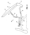
Figures 1-4 , a first embodiment of an articulating decklid system according to the present invention is generally shown at 10. The system is designed for use with a vehicle having abody 12 and aretractable roof 14 that selectively covers apassenger compartment 16 in thebody 12. A seatback is shown at 18, to illustrate the rearmost portion of thepassenger compartment 16. Aluggage compartment 20 is defined in the vehicle body rearwardly of thepassenger compartment 16. - The articulating
decklid system 10 is designed for use with aretractable roof 14 which, when retracted, is stowed in theluggage compartment 20. Therefore, thedecklid system 10 must provide an opening to theluggage compartment 20 for theretractable top 14 to pass through. - The articulating
decklid system 10 includes afirst linkage member 22 that has aforward end 24 pivotally interconnected with the vehicle body and arearward end 26. Adecklid 30 has aforward end 32 and arearward end 34. Therearward end 34 of the decklid is pivotally interconnected with therearward end 26 of thefirst linkage member 22. - A
second linkage assembly 36 has anupper end 38 pivotally interconnected with thedecklid 30 and alower end 40 pivotally interconnected with thefirst linkage member 22 between the forward and rearward ends 24 and 26. Thesecond linkage assembly 36 has a folded position, shown inFigure 1 , wherein theupper end 38 andlower end 40 are separated by a short distance. The second linkage assembly also has an unfolded position, shown inFigures 2-4 , wherein theupper end 38 andlower end 40 are separated by a larger distance. It should be noted that the unfolded positions ofFigures 2 and3 are actually somewhat different, since thedecklid 30 is in different positions, and that theupper end 38 andlower end 40 may not be separated by the same distance in both of these unfolded positions. However, they will both be referred to as unfolded positions herein. -
Figure 1 illustrates thedecklid system 10 in a closed position. In this position, the rearward ends 26 and 34 of the first linkage member and the decklid are adjacent the rearward end of theluggage compartment 20, thesecond linkage assembly 36 is in the folded position, and theforward end 32 of thedecklid 30 is adjacent the forward end of the luggage compartment. It should be noted that when portions of the decklid system are referred to as being adjacent certain portions of the luggage compartment, they may also be considered to be adjacent corresponding portions of the vehicle body. -
Figure 2 illustrates the decklid system in a luggage receiving position, wherein a rearwardly facing opening is provided to receive luggage into theluggage compartment 20. As shown, in the luggage receiving position, the rearward ends, 26 and 34, of thefirst linkage member 22 and decklid 30 are spaced from the rearward end of the luggage compartment and the vehicle body. The angular movement of thefirst linkage member 22 also causes thesecond linkage assembly 36 to move to the unfolded position such that thedecklid 30 articulates upwardly and forwardly. This also moves theforward end 32 of thedecklid 30 to a position spaced from the forward end of the luggage compartment and the vehicle body. -
Figure 3 illustrates the decklid system in a top receiving position, wherein a forwardly facing opening is provided for the passage of the retractable roof or top therethrough. In the top receiving position, the rearward ends, 26 and 34, of thefirst linkage member 22 and decklid 30 are adjacent the rearward end of the luggage compartment and the vehicle body. Thesecond linkage assembly 36 is moved to the unfolded position, thereby rotating thedecklid 30 upwardly and rearwardly. Therefore, theforward end 32 of thedecklid 30 is spaced from the forward end of the luggage compartment and from the vehicle body. - Referring to
Figure 4 , thefirst linkage member 22 is preferably a generally U-shaped member having a pair of spaced apartside portions 42 and 44. Theside portions 42 and 44 preferably extend longitudinally along the sides of theluggage compartment 20. Theside portions 42 and 44 have forward ends that are pivotally connected to the vehicle body and define the forward end of thefirst linkage member 22. Thefirst linkage member 22 also includes a connectingportion 46 that extends transversely between the rearward ends of theside portions 42 and 44. This connecting portion defines the rearward end of thelinkage member 22. As shown, the forward end of thefirst linkage member 22 is pivotally connected to the vehicle body via brackets, one of which is shown at 48. Preferably, the pivotal interconnection between thefirst linkage member 22 and thebrackets 48 is a simple pivot that defines a pivot axis. Alternatively, a more complicated pivoting mechanism, such as a four-bar or six-bar linkage, may be provided. Such an arrangement is considered a pivotal interconnection for the purposes of the present invention. Therearward end 26 of thefirst linkage member 22 is preferably latched to the vehicle body using alatch 50, shown inFigure 1 . Thislatch 50 may take the form of a traditional trunk latch, or other types of latches may be used. One centrally located latch on the connectingportion 46 is preferred, though multiple latches or latches in different positions may be used. For example, latches may be provided for connecting theside portions 42 and/or 44 to the vehicle body. - The
decklid 30 is preferably interconnected with the connectingportion 46 of thefirst linkage member 22 by a simple pivot. However, more complex pivotal interconnections, such as four or six-bar linkages, may be used. For purposes of the present invention, these fall within the definition of a pivotal interconnection. In the illustrated embodiment, the simple pivotal connection between thefirst linkage member 22 and thedecklid 30 causes a portion of therearward end 34 of the decklid to move downwardly as it pivots, as shown inFigure 3 . A more complex pivotal interconnection may change this motion profile. Alternatively, the location of the pivot may be changed so as to change the motion profile. - The
second linkage assembly 36 may take a variety of forms, but preferably includes anupper link 52 and alower link 54 that are pivotally interconnected to one another. The upper end of theupper link 52 is pivotally interconnected with thedecklid 30 adjacent one of its sides, while the lower end of thelower link 54 is pivotally interconnected with thecorresponding side portion 42 of thefirst linkage member 22. Anactuator 56 has one end pivotally interconnected with the vehicle body, as represented bybracket 48, and the other end pivotally interconnected with thelower link 54 between its upper and lower ends. - The
actuator 56 is preferably a hydraulic linear actuator, but may alternatively be a different type of actuator. Theactuator 56 has a retracted position, shown inFigures 1 and2 , and an extended position shown inFigures 3 and4 . As shown, the pivotal interconnection between the actuator 56 and the body is preferably forward of the pivotal interconnection between thefirst linkage member 22 and the vehicle body. Theactuator 56 is also preferably lockable in its retracted position, such as inFigure 1 . By locking theactuator 56, thedecklid 30 is retained in the closed position. Preferably, no other latch is provided between the forward portion of the decklid and the vehicle body. - When the
decklid system 10 is moved between the closed position ofFigure 1 and
the luggage receiving position ofFigure 2 , theactuator 56 is retained in its retracted position. In this situation, the vehicle body, represented bybracket 48, theactuator 56, thefirst linkage bar 22, and thelower link 54 form a four-bar linkage. As thefirst linkage member 22 rotates counter-clockwise, as shown inFigure 2 , this causes thesecond linkage assembly 36 to move to the unfolded position, thereby moving theforward end 32 of thedecklid 30 upwardly and forwardly. This causes the decklid to move up over thevehicle top 14, but also to be move forwardly sufficiently to provide access to the luggage compartment. - The
decklid system 10 may be moved from the closed position ofFigure 1 to the top receiving position ofFigures 3 and4 by extending theactuator 56, while maintaining thefirst linkage member 22 in its original position, in which its rearward end may be latched to the body. This causes thedecklid 30 to pivot about the pivotal interconnection between therearward end 26 of the first linkage member and therearward end 34 of thedecklid 30. Thesecond linkage assembly 36 is moved to its unfolded position by the movement of theactuator 56. - Referring to
Figure 4 , the second linkage assembly previously discussed is illustrated as being on one side of the vehicle. Preferably, an additional linkage assembly, referred to as a third linkage assembly, is provided on the other side of the vehicle, as shown at 58. A correspondingactuator 60 is also provided. These are preferably identical to the linkage assembly and actuator on the other side of the vehicle. - Referring now to
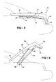
Figures 5-7 , a second embodiment of an articulating decklid system according to the present invention is generally shown at 80. The system includes afirst linkage member 82 with aforward end 84 pivotally interconnected with the vehicle body and arearward end 86. Adecklid 88 has aforward end 90 and arearward end 92. Therearward end 92 is preferably pivotally interconnected with therearward end 86 of thefirst linkage member 82. As with the prior embodiment, thefirst linkage member 82 is preferably U-shaped, and the pivots between the first linkage member and the vehicle body and the decklid are preferably simple pivots. Also, there is preferably a latch provided between therearward end 86 of the first linkage member and the vehicle body. - An
actuator 94 has afirst end 96 pivotally interconnected to thedecklid 88 and asecond end 98 pivotally interconnected to the vehicle body. Theactuator 94 is preferably a hydraulic actuator, but may also be a different type of linear actuator. Theactuator 94 has a retracted position, shown inFigure 5 , and an extended position shown inFigure 7 . As shown, the pivotal interconnection between theforward end 98 of theactuator 94 is preferably forward of the pivotal interconnection between theforward end 84 of thefirst linkage member 82 and the vehicle body. The pivotal interconnection between thefirst end 96 of theactuator 94 and thedecklid 88 is preferably a significant distance rearward. In the illustrated embodiment, the pivotal interconnection is more than halfway back thedecklid 88. In the illustrated embodiment, theactuator 94 has both of its ends positioned above thefirst linkage member 82. When thedecklid system 80 moves from the closed position ofFigure 5 to the luggage receiving position ofFigure 6 , theactuator 94 is retained in the shortened position and serves as one link in a four-bar linkage. Therefore, thedecklid 80 articulates upwardly and forwardly as it rotates counterclockwise as viewed inFigure 6 . Theactuator 94 is preferably lockable in its retracted position so that it serves as a link. To move thedecklid system 80 from the closed position ofFigure 5 to the top receiving position ofFigure 7 , theactuator 94 is moved to its extended position, which causes thedecklid 88 to rotate clockwise, as shown. - Referring now to
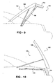
Figures 8-10 , a third embodiment of an articulating decklid system according to the present invention is generally shown at 100. This embodiment is very similar to the Figures of 5-7, except thedecklid 102 is two pieces rather than one. Arearward piece 104 defines the rear portion of thedecklid 102 and aforward portion 106 defines the forward part. Theportions rearward portion 104 is preferably connected rigidly to the rearward end of thefirst linkage member 108. Therefore, as thedecklid system 100 moves from the closed position ofFigure 8 to either the luggage receiving position ofFigure 9 or the top receiving position ofFigure 10 , theforward portion 106 of the decklid pivots relative to therearward portion 104, rather than the entire decklid pivoting relative to thefirst linkage member 108. As will be clear to those of skill in the art, thefirst linkage member 108 and therear portion 104 of the decklid may be formed together, or rigidly interconnected. Also, therearward portion 104 may form, or replace, the transversely extending connection portion of themember 108. As is also clear to those of skill in the art, the two-piece decklid design ofFigures 8-10 may be applied to the first embodiment of the present invention, shown inFigures 1-4 . - As a further alternative to the various designs present herein, the illustrated actuators may be altered or repositioned. For example, in the embodiment of
Figures 1-4 , theactuators first linkage member 22. In this case, the actuator would be retracted in both the top receiving and luggage receiving positions to articulate the decklid as shown in the figures. It was previously mentioned that the actuators may be locked in the shortened position. In the earlier embodiment or the presently discussed alternative, the actuators may include the ability to be locked in other positions, such as being lockable in both an extended and retracted position, and/or also be lockable in intermediate positions. As will be clear to those of skill in the art, the various linkages illustrated may be reconfigured without departing from the scope of the invention. For example, the links forming the second linkage assembly may be shorter or longer, or attached in other positions. The other linkage positions and sizes and actuator positions and sizes may also be altered without departing from the scope of the present invention. - The above-described embodiments of the present invention may be altered in various ways without departing from the scope of the present invention. It is the following claims, which define the scope of the present invention.
Claims (23)
- An articulating decklid system (10) for a vehicle having a body (12) and a retractable roof (14) selectively covering a passenger compartment (16) disposed in the body (12), the vehicle further having a luggage storage compartment (20) positioned rearward of the passenger compartment (16) and disposed in the body (12), the luggage compartment (20) having a forward end and a rearward end, the system (10) comprising:a first linkage member (22) having a forward end (24) pivotally interconnected with the vehicle body (12) and a rearward end (26) spaced therefrom;a decklid (30) having a forward end (32) and a rearward end (34), the rearward end (34) being pivotally interconnected with the rearward end (26) of the first linkage member (22);a second linkage assembly (36) having an upper end (38) pivotally interconnected with the decklid (30) and a lower end (40);an actuator (56, 60);the decklid system (10) having a first closed position wherein the forward end (32) of the decklid (30) is adjacent the forward end of the luggage compartment (20);the decklid system (10) having a second top receiving position wherein the forward end (32) of the decklid (30) is spaced from the vehicle body (12) so as to define a generally forward facing opening to receive the retractable roof (14) therethrough; andthe decklid system (10) having a third luggage receiving position to define a generally rearward facing opening to receive luggage therethrough, and the forward end (32) of the decklid (30) is spaced from the forward end of the luggage compartment (20);characterized in thatthe lower end (40) of the second linkage assembly (36) is pivotally interconnected with the first linkage member (22) between the forward (24) and rearward ends (26), the second linkage assembly (36) has a folded position wherein the upper end (38) and the lower end (40) are separated by a first distance and an unfolded position wherein the upper (38) and lower ends (40) are separated by a distance greater than the first distance;wherein in the first closed position of the decklid system (10) the rearward ends (26) of the first linkage member (22) and the decklid (30) are adjacent the rearward end of the luggage compartment (20), and the second linkage assembly (36) is in the folded position;wherein in the second top receiving position of the decklid system (10) rearward ends (26) of the first linkage member (22) and the decklid (30) are adjacent the rearward end of the luggage compartment (20), and the second link-age assembly (36) is in the unfolded position; andwherein in the third luggage receiving position of the deck-lid system (10) the rearward ends (26) of the first linkage member (22) and the decklid (30) are spaced from the rearward end of the luggage compartment (20) so as to define the generally rearward facing opening to receive luggage therethrough, and the second linkage assembly (36) is in the unfolded position.
- The articulating decklid system according to claim 1,
wherein the second linkage assembly (36) comprises an upper link (52) and a lower link (54), the lower link (54) having a first end (40) pivotally interconnected to the first linkage member (22) and a second end spaced therefrom, the upper link (52) having a first end pivotally interconnected with the second end of the first linkage member (22) and a second end (38) pivotally interconnected with the decklid (30). - The articulating decklid system according to claim 2, wherein the actuator (56, 60) comprises a linear actuator having a first end pivotally interconnected with the vehicle body (12) and the second end pivotally interconnected with the lower link (54) of the second linkage assembly (36) between the first (40) and second ends of the lower link.
- The articulating decklid system according to claim 1, wherein the actuator (56, 60) comprises a linear actuator having a first end pivotally interconnected with the vehicle body (12) and a second end pivotally interconnected with the second linkage assembly (36) between the upper (38) and lower ends (40).
- The articulating decklid system according to claim 4, wherein the actuator (56, 60) has a retracted position and an extended position wherein the ends are farther apart than in the retracted position, the actuator (56, 60) being in the retracted position when the decklid system (10) is in the closed position and when the decklid system (10) is in the luggage receiving position.
- The articulating decklid system according to claim 5, wherein the actuator (56, 60) and the second linkage assembly (36) are configured such that as the decklid (30) moves between the closed position and the luggage receiving position, the actuator (56, 60) causes the second linkage assembly (36) to move to the unfolded position.
- The articulating decklid system according to claim 1, wherein the pivotal connection between the rearward end (26) of the first linkage member (22) and the decklid (30) defines a first pivot axis, the upper end (38) of second linkage assembly (36) being connected to the deck-lid (30) forward of the first pivot axis.
- The articulating decklid system according to claim 1,
wherein the first linkage member (22) includes a pair of spaced apart side portions (42, 44) each having a forward end (24) and a rearward end (26), the linkage member (22) further including a connecting portion (46) extending between and interconnecting the rearward ends (26) of the side portions (42, 44), the forward ends (24) of the side portions (42, 44) defining the forward end (24) of the first linkage member (22) and the connecting portion (46) defining the rearward end (26) of the first linkage member (22). - The articulating decklid system according to claim 8,
wherein the luggage compartment (20) has a pair of opposed sides extending between the forward and rearward ends, the side portions (42, 44) of the first linkage member (22) being adjacent the sides of the luggage compartment (20). - The articulating decklid system according to claim 1, further comprising a third linkage assembly (58), the lower end (40) of the second linkage assembly (36) being pivotally interconnected with one of the side portions (42, 44 respectively) of the first linkage member (22), the third linkage assembly (58) having an upper end pivotally interconnected with the decklid (30) and a lower end pivotally interconnected with the other side portion (44, 42, respectively) of the first linkage member (22).
- An articulating decklid system (10, 80, 100) for a vehicle having a body (12) and a retractable roof (14) selectively covering a passenger compartment (16) disposed in the body (12), the vehicle further having a luggage storage compartment (20) positioned rearward of the passenger compartment (16) and disposed in the body (12), the luggage compartment (20) having a forward end and a rearward end, the system (10, 80, 100) comprising:a first linkage member (22, 82, 108) having a forward end (24, 84) pivotally interconnected with the vehicle body (12) and a rearward end (26, 86) spaced therefrom;a decklid (30, 88, 102) having a forward end (32, 90) anda rearward end (34, 92);a actuation mechanism (36, 94) at least partially disposed adjacent the forward end of the luggage compartment (20), the mechanism (36, 94) having a first end (38, 96) and a second end (40, 98), the first end (38, 96) being interconnected with the decklid (30, 88, 102) forward of the first pivot axis;the decklid system (10, 80, 100) having a first closed position wherein the forward end (32, 90) of the decklid (30, 88, 102) is adjacent the forward end of the luggage compartment (20);the decklid system (10, 80, 100) having a second top receiving position wherein the forward end (32, 90) of the decklid (30, 88, 102) is spaced from the vehicle body (12) so as to define a generally forward facing opening to receive the retractable roof (14) therethrough; andthe decklid (30, 88, 102) having a third luggage receiving position to define a generally rearward facing opening to receive luggage therethrough;characterized in thatthe rearward end (34, 92) of the decklid (30, 88, 102) is pivotally interconnected with the rearward end (26, 86) of the first linkage member (22, 82, 108) so as to define a first pivot axis;the actuation mechanism (36, 94) has a retracted position wherein the first end (38, 96) and the second end (40, 98) are separated by a first distance and an extend-ed position wherein the first (38, 96) and second ends (40, 98) are separated by a distance greater than the first distance;wherein in the first closed position of the decklid system (10, 80, 100) the rearward ends (26, 86) of the first linkage member (22, 82, 108) and the decklid (30, 88, 102) are adjacent the rearward end of the luggage compartment (20), and the actuation mechanism (36, 94) is in the retracted position;wherein in the second top receiving position of the decklid system (10, 80, 100) rearward ends (26, 86) of the first linkage member (22, 82, 108) and the decklid (30, 88, 102) are adjacent the rearward end of the luggage compartment (20), and the actuation mechanism (36, 94) is in the extended position; andwherein in the third luggage receiving position of the deck-lid (30, 88, 102) the rearward ends (26, 86) of the first linkage member (22, 82, 108) and the decklid (30, 88, 102) are spaced from the rearward end of the luggage compartment (20) so as to define the generally rearward facing opening to receive luggage therethrough.
- The articulating decklid system according to claim 11, wherein the second end (40) of the actuation mechanism (36) is pivotally interconnected with the first linkage member (22) between the forward (24) and rearward ends (26), the actuation mechanism (36) being in the extended position when the decklid system (10) is in the luggage receiving position.
- The articulating decklid system according to claim 11, wherein the second end (98) of the actuation mechanism (94) is pivotally interconnected with the vehicle body (12), the second end (98) being disposed forward of the first end (96), the actuation mechanism (94) being in the retracted position when the decklid (88, 102) is in the luggage receiving position.
- The articulating decklid system according to claim 11, wherein the actuation mechanism (36, 94) comprises a linear actuator (56, 60, 94), the actuator (56, 60, 94) having a retracted position and an extended position wherein the ends (38, 40, 96, 98) are farther apart than in the retracted position, the actuator (56, 60, 94) being in the retracted position when the decklid system (10, 80, 100) is in the closed position and when the decklid system (10, 80, 100) is in the luggage receiving position.
- The articulating decklid system according to claim 4 or 14, wherein the pivotal interconnection between the first end (96) of the actuator (56, 60, 94) and the vehicle body (12) is disposed forward of the pivotal interconnection between the forward end (24, 84) of the first link-age member (22, 82, 108) and the vehicle body (12).
- An articulating decklid system (80, 100) for a vehicle having a body (12) and a retractable roof (14) selective-ly covering a passenger compartment (16) disposed in the body (12), the vehicle further having a luggage storage compartment (20) positioned rearward of the passenger compartment (16) and disposed in the body (12), the lug-gage compartment (20) having a forward end and a rearward end, the system (80, 100) comprising;
a first linkage member (82, 108) having a forward end (84) pivotally interconnected with the vehicle body (12) and a rearward end (86) spaced therefrom;
a decklid (88, 102) having a forward end (90) and a rearward end (92), the rearward end (92) being interconnected with the rearward end (86) of the first linkage member (82, 108);
a actuator (94);
the decklid system (80, 100) having a first closed position wherein the forward end (90) of the decklid (88, 102) is adjacent the forward end of the luggage compart-ment (20);
the decklid system (80, 100) having a second top receiving position wherein the forward end (90) of the decklid (88, 102) is spaced from the vehicle body (12) so as to define a generally forward facing opening to receive the retractable roof (14) therethrough; and
the decklid (88, 102) having a third luggage receiving position to define a generally rearward facing opening to receive luggage therethrough, and the forward end (90) of the decklid (88, 102) is spaced from the forward end of the luggage compartment (20);
characterized in that
the actuator (94) has a first end (96) connected to the decklid (88, 102) forward of the rearward end (92) of the decklid (88, 102) and a second end (98) connected to the body (12), the actuator (94) has a retracted position wherein the first end (96) and the second end (98) are separated by a first distance and an extended position wherein the first (96) and second ends (98) are sep-orated by a distance greater than the first distance;
wherein in the first closed position of the decklid system (80, 100) the rearward ends (86) of the first linkage member (82, 108) and the decklid (88, 102) are adjacent the rearward end of the luggage compartment (20), and the actuator (94) is in the retracted position;
wherein in the second top receiving position of the decklid system (80, 100) the rearward ends (86) of the first linkage member (82, 108) and the decklid (88, 102) are adjacent the rearward end of the luggage compartment (20), and the actuator (94) is in the extended position; and
wherein in the third luggage receiving position of the deck-lid (88, 102) the rearward ends (86) of the first linkage member (82, 108) and the decklid (88, 102) are spaced from the rearward end of the luggage compartment (20) so as to define the generally rearward facing opening to receive luggage therethrough, and the actuator (94) is in the retracted position;
wherein the body (12), the actuator (94), the decklid (88, 102), and the first linkage member (82, 108) form a four bar mechanism when the decklid (88, 102) moves from the first closed position to the third luggage receiving position. - The articulating decklid system according to claim 16, wherein the interconnection between the rearward end (92) of the decklid (88, 102) and the rearward end (86) of the first linkage member (82, 108) is a pivotal interconnection.
- The articulating decklid system according to claim 16, wherein the decklid (102) is a two piece decklid (102) with a forward portion (106) pivotally interconnected with a rearward portion (104).
- The articulating decklid system according to any of claims 1, 11 or 16, wherein the pivotal interconnection between the forward end (24, 84) of the first linkage member (22, 82) and the vehicle body (12) is adjacent the forward end of the luggage compartment (20).
- The articulating decklid system according to any of claims 1 or 16, further comprising a latch (50) for selectively latching the first linkage member (22, 82) to the body (12), the first linkage member (22, 82) being latched to the vehicle body (12) when the decklid system (10, 80, 100) is in the closed position and in the top receiving position.
- The articulating decklid system according to claim 20, wherein the latch (50) interconnects the rearward end (26, 86) of the first linkage member (22, 82) with the vehicle body (12).
- The articulating decklid system according to claim 5 or 16, wherein the actuator (56, 60, 94) is lockable in the retractable position, the actuator (56, 60, 94) being locked in the retracted position when the decklid system (10, 80, 100) is in the closed position, the locked actuator (56, 60, 94) serving as the only latch for retaining the forward end (32, 90) of the decklid (30, 88, 102) adjacent the forward end of the luggage compartment (20) when the decklid system (10, 80, 100) is in the closed position.
- The articulating decklid system according to claim 16, wherein the connection between the first end (96) of the actuator (94) and the vehicle body (12) is disposed forward of the pivotal interconnection between the forward end (84) of the first linkage member (82) and the vehicle body (12).
Applications Claiming Priority (7)
| Application Number | Priority Date | Filing Date | Title |
|---|---|---|---|
| US443635 | 1989-11-29 | ||
| US38266202P | 2002-05-23 | 2002-05-23 | |
| US382662P | 2002-05-23 | ||
| US46381703P | 2003-04-18 | 2003-04-18 | |
| US463817P | 2003-04-18 | ||
| US10/443,635 US6899368B2 (en) | 2002-05-23 | 2003-05-22 | Decklid mechanism for vehicle with retractable top |
| PCT/US2003/016507 WO2003099598A2 (en) | 2002-05-23 | 2003-05-23 | Decklid mechanism for vehicle with retractable top |
Publications (3)
| Publication Number | Publication Date |
|---|---|
| EP1549519A2 EP1549519A2 (en) | 2005-07-06 |
| EP1549519A4 EP1549519A4 (en) | 2012-03-21 |
| EP1549519B1 true EP1549519B1 (en) | 2014-09-10 |
Family
ID=29554257
Family Applications (1)
| Application Number | Title | Priority Date | Filing Date |
|---|---|---|---|
| EP03755489.6A Expired - Lifetime EP1549519B1 (en) | 2002-05-23 | 2003-05-23 | Decklid mechanism for vehicle with retractable top |
Country Status (4)
| Country | Link |
|---|---|
| US (1) | US6899368B2 (en) |
| EP (1) | EP1549519B1 (en) |
| AU (1) | AU2003231849A1 (en) |
| WO (1) | WO2003099598A2 (en) |
Families Citing this family (12)
| Publication number | Priority date | Publication date | Assignee | Title |
|---|---|---|---|---|
| DE10214980B4 (en) * | 2002-04-04 | 2007-04-12 | Magna Car Top Systems Gmbh | Rear lid for a convertible vehicle |
| FR2840582B1 (en) * | 2002-06-11 | 2004-12-24 | France Design | REAR TRUNK COVER FOR VEHICLE WITH FOLDABLE ROOF |
| FR2846285B1 (en) * | 2002-10-29 | 2004-12-24 | France Design | RETRACTABLE ROOF FOR MOTOR VEHICLE |
| DE10340017B3 (en) * | 2003-08-28 | 2004-08-12 | Cts Fahrzeug-Dachsysteme Gmbh | Rear cover for cabriolet automobile using multiple linkage mechanism for movement of rear cover between closed position and raised position providing access to storage compartment for cabriolet roof |
| DE102005006272A1 (en) * | 2005-02-10 | 2006-08-17 | Wilhelm Karmann Gmbh | Motor vehicle with a lid part which can be opened in two senses |
| DE102005026281A1 (en) * | 2005-06-08 | 2006-12-14 | Wilhelm Karmann Gmbh | Convertible vehicle with a roof which can be deposited underneath a cover |
| US7762607B2 (en) * | 2006-12-21 | 2010-07-27 | Wilhelm Karmann Gmbh | Overcenter linkage mechanism for a decklid of an automotive vehicle |
| DE102007006518B4 (en) * | 2007-02-09 | 2011-09-22 | Webasto-Edscha Cabrio GmbH | Linkage for a trunk lid |
| DE102007056180B4 (en) | 2007-11-21 | 2014-04-03 | Webasto Ag | Vehicle with a convertible roof |
| DE102008005603A1 (en) * | 2008-01-22 | 2009-07-23 | Wilhelm Karmann Gmbh | Cabriolet vehicle with an up and zubewegbaren surface part |
| DE102009006721B4 (en) * | 2009-01-29 | 2016-04-28 | Audi Ag | Actuation device for a top compartment lid |
| JP5981653B2 (en) * | 2012-08-06 | 2016-08-31 | カウンシル オブ サイエンティフィック アンド インダストリアル リサーチ | Bioreactor vessel for large-scale growth of plants under aseptic conditions |
Family Cites Families (51)
| Publication number | Priority date | Publication date | Assignee | Title |
|---|---|---|---|---|
| US1253641A (en) | 1917-04-10 | 1918-01-15 | William E Steele | Hinge. |
| US1774199A (en) | 1929-10-31 | 1930-08-26 | H H Martz | Tonneau construction |
| US1933623A (en) | 1931-03-30 | 1933-11-07 | Jules H Bernheim | Convertible vehicle body |
| US2181869A (en) | 1935-08-10 | 1939-12-05 | Raymond L Carr | Vehicle body |
| US2947570A (en) | 1957-03-14 | 1960-08-02 | Ford Motor Co | Motor vehicle body telescopic roof construction |
| US3021174A (en) | 1958-09-04 | 1962-02-13 | John C Rund | Hardtop convertible automobile structure |
| US3180677A (en) | 1962-09-18 | 1965-04-27 | Gen Motors Corp | Vehicle body |
| JPS59179974U (en) | 1983-05-19 | 1984-12-01 | トヨタ自動車株式会社 | car side door hinge |
| JPH05112256A (en) | 1991-10-21 | 1993-05-07 | Honda Motor Co Ltd | Bi-directional single-sided lid |
| DE4320468C1 (en) | 1993-06-21 | 1994-10-20 | Daimler Benz Ag | Motor vehicle with a lowerable roof construction |
| DE4322285C1 (en) | 1993-07-05 | 1994-06-23 | Daimler Benz Ag | Arrangement of a boot lid or the like on the body frame of a vehicle |
| DE4445580C1 (en) | 1994-12-20 | 1995-12-21 | Daimler Benz Ag | Hard=top vehicle roof linkage |
| DE4445944C1 (en) | 1994-12-22 | 1996-04-25 | Daimler Benz Ag | Hard top motor car |
| DE4445920C2 (en) | 1994-12-22 | 1997-02-20 | Daimler Benz Ag | Motor vehicle with retractable roof construction |
| DE19514388C2 (en) | 1995-04-19 | 2002-04-18 | Scharwaechter Gmbh Co Kg | Door or flap hinge for motor vehicles |
| DE19516876C1 (en) | 1995-05-09 | 1996-11-28 | Daimler Benz Ag | Drive arrangement for moving a lockable vehicle part |
| DE19516877C1 (en) | 1995-05-09 | 1996-10-17 | Daimler Benz Ag | Hardtop vehicle |
| DE19613917C2 (en) | 1996-04-06 | 1998-01-15 | Daimler Benz Ag | Cover arrangement for a convertible top compartment arranged in the rear area of a vehicle |
| DE19635536C1 (en) | 1996-09-02 | 1998-01-22 | Daimler Benz Ag | Movable roof-structure for convertible car |
| DE19637005C1 (en) | 1996-09-12 | 1997-12-18 | Daimler Benz Ag | Plate covering for front area of frame opening of hood box |
| FR2759052B1 (en) | 1997-02-05 | 1999-03-12 | France Design | REAR TRUNK FOR DISCOVERABLE VEHICLE |
| DE19737057A1 (en) | 1997-08-26 | 1999-03-04 | Edscha Cabrio Verdecksys Gmbh | Retractable fixed roof |
| DE19746569C2 (en) | 1997-10-22 | 2000-10-26 | Daimler Chrysler Ag | Convertible top |
| DE19751660C1 (en) | 1997-11-21 | 1999-03-18 | Daimler Benz Ag | Stowage for motor vehicle hard top |
| DE19756062C1 (en) | 1997-12-17 | 1999-04-01 | Daimler Benz Ag | Cabriolet motor vehicle hood |
| DE19803155C1 (en) | 1998-01-28 | 1999-08-12 | Daimler Chrysler Ag | Rear lid mounting for convertible motor vehicle |
| FR2777243B1 (en) | 1998-04-09 | 2000-06-09 | France Design | REAR TRUNK FOR DISCOVERABLE VEHICLE WITH FOLDABLE ROOF |
| FR2777242B1 (en) | 1998-04-09 | 2000-06-09 | France Design | PIVOTING AND SLIDING REAR TRUNK FOR DISCOVERABLE VEHICLE WITH FOLDABLE ROOF |
| FR2777240B1 (en) | 1998-04-09 | 2000-06-09 | France Design | REAR TRUNK FOR DISCOVERABLE VEHICLE WITH FOLDABLE ROOF, COMPRISING A REAR TRUNK AND A REAR BEACH |
| FR2777241B1 (en) | 1998-04-09 | 2000-06-09 | France Design | REAR TRUNK FOR DISCOVERABLE VEHICLE WITH FOLDING ROOF, THIS TRUNK CAN OPEN FROM THE REAR TO THE FRONT AND FROM THE FRONT TO THE REAR |
| DE19825651C2 (en) | 1998-06-09 | 2001-10-31 | Daimler Chrysler Ag | Motor vehicle with an opening top |
| US5944378A (en) | 1998-07-23 | 1999-08-31 | Chrysler Corporation | Two-part convertible top for a motor vehicle |
| DE19841103C1 (en) | 1998-09-09 | 2000-03-16 | Daimler Chrysler Ag | Hard top road vehicle has front roof part and rear roof part provided with fixed rear plate, lateral main guides for movement of front and rear parts and side vehicle columns |
| JP2000104445A (en) | 1998-09-29 | 2000-04-11 | Toyota Motor Corp | Luggage opening and closing mechanism |
| DE19910763C1 (en) | 1999-03-11 | 2000-07-13 | Daimler Chrysler Ag | Motor vehicle boot lid operator comprizes strut tubes whose locking wedge is freed or engaged with receiver mounting by pulling respective bowden cable ties off hydraulic cylinder. |
| US6217104B1 (en) | 1999-06-16 | 2001-04-17 | Cts Fahrzeug Dachsysteme Gmbh | Retractable hard top module |
| DE50001935D1 (en) | 1999-07-12 | 2003-06-05 | Webasto Vehicle Sys Int Gmbh | Tailgate of a vehicle |
| DE19940959B4 (en) | 1999-08-28 | 2004-10-21 | Daimlerchrysler Ag | Motor vehicle with a body |
| JP3523816B2 (en) | 1999-10-19 | 2004-04-26 | アイシン精機株式会社 | Luggage panel opening and closing device |
| DE19960012C1 (en) | 1999-12-13 | 2001-02-15 | Cts Fahrzeug Dachsysteme Gmbh | Arrangement for locking two mutually relatively adjustable, guided elements has locking element blocked from moving towards locking position by control drive when in standby position |
| DE19960010C2 (en) | 1999-12-13 | 2003-07-31 | Cts Fahrzeug Dachsysteme Gmbh | Hinged roof for vehicles, in particular passenger cars |
| DE20009572U1 (en) | 2000-05-25 | 2001-10-04 | Wilhelm Karmann GmbH, 49084 Osnabrück | Cabriolet vehicle |
| ATE332246T1 (en) | 2000-07-25 | 2006-07-15 | Pininfarina Spa | TRUNK LID MECHANISM OF A CONVERTIBLE VEHICLE |
| DE10038530B4 (en) | 2000-08-08 | 2011-02-24 | Wilhelm Karmann Gmbh | Cabriolet vehicle with a can be placed under a cover part roof |
| DE10039683B4 (en) | 2000-08-14 | 2005-02-24 | Wilhelm Karmann Gmbh | Convertible car |
| US6824194B2 (en) | 2000-10-20 | 2004-11-30 | Wilhelm Karmann Gmbh | Convertible with a roof, which can be stowed in the rear region of the vehicle below a lid |
| DE10116613C1 (en) | 2001-04-03 | 2002-07-18 | Cts Fahrzeug Dachsysteme Gmbh | Cabriolet vehicle has roof folding up and down through kinematic system and four articulated rods and coupling rod so that it moves within contours of vehicle |
| DE10116710C2 (en) | 2001-04-04 | 2003-03-13 | Edscha Cabrio Dachsys Gmbh | Convertible top for a convertible vehicle |
| DE10135581A1 (en) | 2001-07-20 | 2003-01-30 | Karmann Gmbh W | Cabriolet vehicle with a cover part in the rear area of the vehicle |
| DE10137018C1 (en) | 2001-07-30 | 2003-02-20 | Daimler Chrysler Ag | Support frame of a trunk lid of a rear compartment of a body |
| JP2003104062A (en) | 2001-09-28 | 2003-04-09 | Takada Kogyo Kk | Opening/closing device of rear door for vehicle |
-
2003
- 2003-05-22 US US10/443,635 patent/US6899368B2/en not_active Expired - Fee Related
- 2003-05-23 EP EP03755489.6A patent/EP1549519B1/en not_active Expired - Lifetime
- 2003-05-23 WO PCT/US2003/016507 patent/WO2003099598A2/en not_active Ceased
- 2003-05-23 AU AU2003231849A patent/AU2003231849A1/en not_active Abandoned
Also Published As
| Publication number | Publication date |
|---|---|
| EP1549519A4 (en) | 2012-03-21 |
| EP1549519A2 (en) | 2005-07-06 |
| US6899368B2 (en) | 2005-05-31 |
| AU2003231849A1 (en) | 2003-12-12 |
| WO2003099598A2 (en) | 2003-12-04 |
| AU2003231849A8 (en) | 2003-12-12 |
| US20030218350A1 (en) | 2003-11-27 |
| WO2003099598A3 (en) | 2004-03-25 |
Similar Documents
| Publication | Publication Date | Title |
|---|---|---|
| US5944378A (en) | Two-part convertible top for a motor vehicle | |
| US6164713A (en) | Convertible with a top structure having at least one top part and a rear window part | |
| US6092335A (en) | Trunk lid for convertible vehicle with folding roof, adapted to open from the rear toward the front and from the front toward the rear | |
| US6799788B2 (en) | Decklid mechanism for vehicle with retractable top | |
| US7377574B2 (en) | Retracting mechanism for use with both hard and hybrid retractable tops for vehicles | |
| US6866324B2 (en) | Folding hardtop with rear window articulation | |
| EP2006139B1 (en) | Retractable roof and vehicle with the same | |
| EP1549519B1 (en) | Decklid mechanism for vehicle with retractable top | |
| US8414049B2 (en) | Vehicle cargo system with multi-function tonneau cover | |
| JPH0725245A (en) | Convertible cars and convertible tops | |
| EP2500195B1 (en) | Convertible top having movable outboard panels | |
| US7014247B2 (en) | Hardtop convertible | |
| US7063371B2 (en) | Convertible hardtop roof | |
| JP4212847B2 (en) | Cover device for roof mechanism storage | |
| CA2101898A1 (en) | Top stack convertible top with one-piece header and side rail | |
| EP1555152B1 (en) | Mechanism for use with both hard and hybrid retractable cabrilolet vehicle tops | |
| US6948762B2 (en) | Stowage space cover of a convertible | |
| US7686377B2 (en) | Convertible with a roof which can be stored below a covering | |
| EP1323562B1 (en) | Trunk lid arrangement | |
| JP2009504487A (en) | Folding canopy for cabriolet vehicle |
Legal Events
| Date | Code | Title | Description |
|---|---|---|---|
| PUAI | Public reference made under article 153(3) epc to a published international application that has entered the european phase |
Free format text: ORIGINAL CODE: 0009012 |
|
| 17P | Request for examination filed |
Effective date: 20041223 |
|
| AK | Designated contracting states |
Kind code of ref document: A2 Designated state(s): AT BE BG CH CY CZ DE DK EE ES FI FR GB GR HU IE IT LI LU MC NL PT RO SE SI SK TR |
|
| AX | Request for extension of the european patent |
Extension state: AL LT LV MK |
|
| DAX | Request for extension of the european patent (deleted) | ||
| RBV | Designated contracting states (corrected) |
Designated state(s): DE FR GB IT |
|
| 19U | Interruption of proceedings before grant |
Effective date: 20090629 |
|
| 19W | Proceedings resumed before grant after interruption of proceedings |
Effective date: 20101201 |
|
| A4 | Supplementary search report drawn up and despatched |
Effective date: 20120217 |
|
| RIC1 | Information provided on ipc code assigned before grant |
Ipc: B60J 7/20 20060101AFI20120213BHEP |
|
| 17Q | First examination report despatched |
Effective date: 20120619 |
|
| RAP1 | Party data changed (applicant data changed or rights of an application transferred) |
Owner name: VALMET AUTOMOTIVE OY |
|
| GRAP | Despatch of communication of intention to grant a patent |
Free format text: ORIGINAL CODE: EPIDOSNIGR1 |
|
| INTG | Intention to grant announced |
Effective date: 20131209 |
|
| GRAS | Grant fee paid |
Free format text: ORIGINAL CODE: EPIDOSNIGR3 |
|
| GRAP | Despatch of communication of intention to grant a patent |
Free format text: ORIGINAL CODE: EPIDOSNIGR1 |
|
| INTG | Intention to grant announced |
Effective date: 20140613 |
|
| GRAA | (expected) grant |
Free format text: ORIGINAL CODE: 0009210 |
|
| AK | Designated contracting states |
Kind code of ref document: B1 Designated state(s): DE FR GB IT |
|
| REG | Reference to a national code |
Ref country code: GB Ref legal event code: FG4D |
|
| REG | Reference to a national code |
Ref country code: DE Ref legal event code: R096 Ref document number: 60346736 Country of ref document: DE Effective date: 20141016 |
|
| REG | Reference to a national code |
Ref country code: DE Ref legal event code: R097 Ref document number: 60346736 Country of ref document: DE |
|
| PLBE | No opposition filed within time limit |
Free format text: ORIGINAL CODE: 0009261 |
|
| STAA | Information on the status of an ep patent application or granted ep patent |
Free format text: STATUS: NO OPPOSITION FILED WITHIN TIME LIMIT |
|
| 26N | No opposition filed |
Effective date: 20150611 |
|
| PG25 | Lapsed in a contracting state [announced via postgrant information from national office to epo] |
Ref country code: IT Free format text: LAPSE BECAUSE OF FAILURE TO SUBMIT A TRANSLATION OF THE DESCRIPTION OR TO PAY THE FEE WITHIN THE PRESCRIBED TIME-LIMIT Effective date: 20140910 |
|
| GBPC | Gb: european patent ceased through non-payment of renewal fee |
Effective date: 20150523 |
|
| REG | Reference to a national code |
Ref country code: FR Ref legal event code: ST Effective date: 20160129 |
|
| PG25 | Lapsed in a contracting state [announced via postgrant information from national office to epo] |
Ref country code: GB Free format text: LAPSE BECAUSE OF NON-PAYMENT OF DUE FEES Effective date: 20150523 |
|
| PG25 | Lapsed in a contracting state [announced via postgrant information from national office to epo] |
Ref country code: FR Free format text: LAPSE BECAUSE OF NON-PAYMENT OF DUE FEES Effective date: 20150601 |
|
| PGFP | Annual fee paid to national office [announced via postgrant information from national office to epo] |
Ref country code: DE Payment date: 20160622 Year of fee payment: 14 |
|
| REG | Reference to a national code |
Ref country code: DE Ref legal event code: R119 Ref document number: 60346736 Country of ref document: DE |
|
| PG25 | Lapsed in a contracting state [announced via postgrant information from national office to epo] |
Ref country code: DE Free format text: LAPSE BECAUSE OF NON-PAYMENT OF DUE FEES Effective date: 20171201 |