JP2008131663A - Rotating electric machine, compressor, blower, air conditioner - Google Patents
Rotating electric machine, compressor, blower, air conditioner Download PDFInfo
- Publication number
- JP2008131663A JP2008131663A JP2006310161A JP2006310161A JP2008131663A JP 2008131663 A JP2008131663 A JP 2008131663A JP 2006310161 A JP2006310161 A JP 2006310161A JP 2006310161 A JP2006310161 A JP 2006310161A JP 2008131663 A JP2008131663 A JP 2008131663A
- Authority
- JP
- Japan
- Prior art keywords
- rotating electrical
- electrical machine
- field element
- teeth
- peripheral side
- Prior art date
- Legal status (The legal status is an assumption and is not a legal conclusion. Google has not performed a legal analysis and makes no representation as to the accuracy of the status listed.)
- Granted
Links
Images
Classifications
-
- H—ELECTRICITY
- H02—GENERATION; CONVERSION OR DISTRIBUTION OF ELECTRIC POWER
- H02K—DYNAMO-ELECTRIC MACHINES
- H02K16/00—Machines with more than one rotor or stator
- H02K16/04—Machines with one rotor and two stators
-
- H—ELECTRICITY
- H02—GENERATION; CONVERSION OR DISTRIBUTION OF ELECTRIC POWER
- H02K—DYNAMO-ELECTRIC MACHINES
- H02K1/00—Details of the magnetic circuit
- H02K1/06—Details of the magnetic circuit characterised by the shape, form or construction
- H02K1/22—Rotating parts of the magnetic circuit
- H02K1/27—Rotor cores with permanent magnets
- H02K1/2706—Inner rotors
- H02K1/272—Inner rotors the magnetisation axis of the magnets being perpendicular to the rotor axis
- H02K1/274—Inner rotors the magnetisation axis of the magnets being perpendicular to the rotor axis the rotor consisting of two or more circumferentially positioned magnets
- H02K1/2753—Inner rotors the magnetisation axis of the magnets being perpendicular to the rotor axis the rotor consisting of two or more circumferentially positioned magnets the rotor consisting of magnets or groups of magnets arranged with alternating polarity
- H02K1/276—Magnets embedded in the magnetic core, e.g. interior permanent magnets [IPM]
Landscapes
- Engineering & Computer Science (AREA)
- Power Engineering (AREA)
- Iron Core Of Rotating Electric Machines (AREA)
Abstract
【課題】回転電機のトルクを大きくしつつも、当該回転電機を小型化することが目的とされる。
【解決手段】回転電機1は、界磁子2と、電機子11,12とを備える。電機子11は界磁子2の外周側に配置される。ティース111は界磁子2に対して外周側から対向する。ティース111には、所定の軸92に沿う一方向91を向き、当該一方向91へと順に配置される端面111a,111bが含まれる。電機子12は界磁子2の内周側に配置される。ティース121には、所定の軸92に沿う一方向91を向き、当該一方向91へと順に配置される端面121a,121bが含まれる。端面111aは、端面121aに対して一方向91へと退いている。端面111bは、端面121bに対して一方向91とは反対方向へと退いている。巻線113の端113aと端面111aとの間の距離W1aは、巻線123の端123aと端面121aとの間の距離W2aよりも大きい。
【選択図】図2An object of the present invention is to reduce the size of a rotating electrical machine while increasing the torque of the rotating electrical machine.
A rotating electrical machine includes a field element and armatures. The armature 11 is disposed on the outer peripheral side of the field element 2. The teeth 111 face the field element 2 from the outer peripheral side. The teeth 111 include end faces 111a and 111b that face one direction 91 along a predetermined axis 92 and are sequentially arranged in the one direction 91. The armature 12 is disposed on the inner peripheral side of the field element 2. The teeth 121 include end faces 121 a and 121 b that face in one direction 91 along a predetermined axis 92 and are sequentially arranged in the one direction 91. The end surface 111a recedes in one direction 91 with respect to the end surface 121a. The end surface 111b recedes in a direction opposite to the one direction 91 with respect to the end surface 121b. A distance W1a between the end 113a of the winding 113 and the end face 111a is larger than a distance W2a between the end 123a of the winding 123 and the end face 121a.
[Selection] Figure 2
Description
本発明は回転電機に関し、特に二つの電機子を有する回転電機に関する。 The present invention relates to a rotating electrical machine, and more particularly to a rotating electrical machine having two armatures.
電動機などの回転電機は、小型化され、効率が高められることが望ましい。例えば、磁束を磁石で励磁する電動機は、サイズが小さくすることが可能である。 It is desirable that a rotating electrical machine such as an electric motor is miniaturized and the efficiency is increased. For example, the size of an electric motor that excites magnetic flux with a magnet can be reduced.
一方、回転電機で発生するトルクは、電機子に配置された巻線の巻数、巻線に流れる電流、及び巻線に鎖交する磁束の量に比例する。回転電機のサイズは大きい程、巻線の巻数を増やすことができ、以って磁束の量を増やすことができる。また、回転電機のサイズは大きい程、界磁子に設けられる磁石の磁極面積を大きくすることができ、以って巻線に鎖交する磁束の量を増やすことができる。よって、トルクを高めるという観点からは、回転電機のサイズは大きい方が望ましい。 On the other hand, the torque generated in the rotating electrical machine is proportional to the number of windings arranged in the armature, the current flowing through the windings, and the amount of magnetic flux interlinked with the windings. The larger the size of the rotating electrical machine, the greater the number of turns of the winding, and thus the amount of magnetic flux can be increased. In addition, the larger the size of the rotating electrical machine, the larger the magnetic pole area of the magnet provided in the field element, thereby increasing the amount of magnetic flux interlinked with the winding. Therefore, from the viewpoint of increasing the torque, it is desirable that the size of the rotating electrical machine is large.
すなわち、発生するトルクの増大と、回転電機の小型化とはトレードオフの関係にある。 That is, there is a trade-off relationship between the increase in generated torque and the reduction in size of the rotating electrical machine.
磁石で励磁する電動機において、トルクTと許容損失Wcとの関係は、式(1)で表される。ここで、係数Kmはモータコンスタントと通称される。かかる関係は、例えば下掲の非特許文献1に紹介されている。
In an electric motor excited by a magnet, the relationship between the torque T and the allowable loss Wc is expressed by Expression (1). Here, the coefficient Km is commonly referred to as motor constant. Such a relationship is introduced, for example, in Non-Patent
![]()
![]()
温度上昇と放熱の関係を考慮すれば、寸法が同一の電動機であって冷却条件が同じである場合には、許容損失Wcはほぼ一定であると考えることができる。この場合、係数Kmが大きい程、トルクTが大きくなる。 Considering the relationship between temperature rise and heat dissipation, it can be considered that the allowable loss Wc is substantially constant when the motors have the same dimensions and the cooling conditions are the same. In this case, the torque T increases as the coefficient Km increases.
係数Kmは式(2)で表すことができる。ここで符号pは極対数、符号Φは巻線に鎖交する磁束の量の最大値Φ、符号fsは巻線の占積率、符号Stは巻線用スロットの全断面積、符号ρは巻線の固有抵抗、符号lはコイルの平均長を、それぞれ表す。電流及び磁束の波形はそれぞれ正弦波状とした。また、回転電機のサイズが小さい場合には、回転電機の損失のほとんどは銅損であるため、鉄損を無視した。 The coefficient Km can be expressed by equation (2). Here, the symbol p is the number of pole pairs, the symbol Φ is the maximum value Φ of the amount of magnetic flux interlinked with the winding, the symbol fs is the space factor of the winding, the symbol St is the total sectional area of the winding slot, and the symbol ρ is The specific resistance of the winding, symbol l, represents the average length of the coil. The current and magnetic flux waveforms were sine waves. When the size of the rotating electrical machine is small, most of the loss of the rotating electrical machine is copper loss, so iron loss is ignored.
![]()
![]()
係数Kmを大きくするためには、以下の手段(i)〜(vi)のいずれか少なくとも一つが有効であることが、式(2)からわかる。 It can be seen from equation (2) that at least one of the following means (i) to (vi) is effective in increasing the coefficient Km.
(i)巻線の占積率fsを大きくすること、
(ii)コイルの平均長lを小さくすること、
(iii)巻線の固有抵抗ρを小さくすること、
(iv)巻線に鎖交する磁束量の最大値Φを大きくすること、
(v)極対数pを大きくすること、
(vi)巻線用スロットの全断面積Stを大きくすること。
(i) increasing the space factor fs of the winding;
(ii) reducing the average coil length l;
(iii) reducing the specific resistance ρ of the winding;
(iv) Increasing the maximum value Φ of the amount of magnetic flux linked to the winding,
(v) increasing the number of pole pairs p;
(vi) To increase the total cross-sectional area St of the winding slot.
全断面積Stを大きくするという観点から(手段vi)、二つの電機子を有するモータが提案されている。具体的には、環状を呈する界磁子に対して、内周側及び外周側のそれぞれに電機子が設けられる。当該電動機は、「ダブルアマチュア電動機」と通称されている。かかる技術は、例えば特許文献1に開示されている。
From the viewpoint of increasing the total sectional area St (means vi), a motor having two armatures has been proposed. Specifically, an armature is provided on each of the inner peripheral side and the outer peripheral side of the annular field element. This electric motor is commonly called a “double amateur electric motor”. Such a technique is disclosed in
その他、本発明に関連する技術が特許文献2及び非特許文献2に開示されている。
In addition, technologies related to the present invention are disclosed in
しかし、従来の技術では、回転電機を小型化すればトルクが小さくなるおそれがあった。 However, with the conventional technology, there is a concern that the torque may be reduced if the rotating electrical machine is downsized.
本発明は上述した事情に鑑みてなされたものであり、回転電機のトルクを大きくしつつも、当該回転電機を小型化することが目的とされる。 The present invention has been made in view of the above-described circumstances, and an object thereof is to reduce the size of the rotating electrical machine while increasing the torque of the rotating electrical machine.
この発明の請求項1にかかる回転電機は、所定の軸(92)の周りで環状を呈する界磁子(2)と、前記界磁子の外周側に配置される第1の電機子(11)と、前記界磁子の内周側に配置される第2の電機子(12)とを備え、前記第1の電機子は、前記所定の軸の周りで環状に配置され、それぞれ界磁子に外周側から対向する第1のティース(111)の複数と、前記第1のティースのそれぞれに巻回される第1の巻線(113)とを有し、前記第1のティースは、前記所定の軸に沿う一方向(91)を向き、前記一方向へと順に配置される第1及び第2の端面(111a,111b)を含み、前記第2の電機子は、前記所定の軸の周りで環状に配置され、それぞれ界磁子に内周側から対向する第2のティース(121)の複数と、前記第2のティースのそれぞれに巻回される第2の巻線(123)とを有し、前記第2のティースは、前記一方向を向き、前記一方向へと順に配置される第3及び第4の端面(121a,121b)を含み、前記第1の端面は、前記第3の端面に対して前記一方向へと退き、前記第2の端面は、前記第4の端面に対して前記一方向とは反対方向へと退き、前記一方向について、前記第1の巻線の外周側の端(113a,113b)のうち前記第1のティースに対して前記第1の端面(111a)と同じ側にある第1の端(113a)と、当該第1の端面との間の距離である第1の距離(W1a)は、前記第2の巻線の外周側の端(123a,123b)のうち前記第2のティースに対して前記第3の端面(121a)と同じ側にある第2の端(123a)と、当該第3の端面との間の距離である第2の距離(W2a)よりも大きい。 A rotating electric machine according to a first aspect of the present invention includes a field element (2) having an annular shape around a predetermined axis (92), and a first armature (11) disposed on an outer peripheral side of the field element. ) And a second armature (12) disposed on the inner peripheral side of the field element, wherein the first armature is annularly disposed around the predetermined axis, A plurality of first teeth (111) facing the child from the outer peripheral side, and a first winding (113) wound around each of the first teeth, the first teeth are The first armature includes first and second end faces (111a, 111b) arranged in order in one direction (91) along the predetermined axis and sequentially in the one direction, and the second armature includes the predetermined axis A plurality of second teeth (121) that are arranged in an annular shape around each of the second teeth (121) and face the field elements from the inner peripheral side, A second winding (123) wound around each of the teeth, and the second teeth face the one direction and are arranged in order in the one direction. Including the end surfaces (121a, 121b), the first end surface retracts in the one direction with respect to the third end surface, and the second end surface has the one direction with respect to the fourth end surface. Retreats in the opposite direction, and in the one direction, out of the outer peripheral ends (113a, 113b) of the first winding on the same side as the first end face (111a) with respect to the first teeth. The first distance (W1a), which is the distance between a certain first end (113a) and the first end face, is the above-mentioned end (123a, 123b) on the outer peripheral side of the second winding. A second end (12 on the same side as the third end face (121a) with respect to the second tooth. And a), greater than the second distance such that the distance between the third end face (W2a).
この発明の請求項2にかかる回転電機は、請求項1記載の回転電機であって、前記一方向(91)について、前記第1の端(113a)の位置と前記第2の端(123a)の位置とは略一致する。 A rotating electrical machine according to a second aspect of the present invention is the rotating electrical machine according to the first aspect, wherein the position of the first end (113a) and the second end (123a) in the one direction (91). Is substantially coincident with the position of.
この発明の請求項3にかかる回転電機は、請求項1または請求項2記載の回転電機であって、前記一方向について、前記第1の巻線の外周側の前記端(113a,113b)のうち前記第1のティース(111)に対して前記第2の端面(111b)と同じ側にある第3の端(113b)と、当該第2の端面との間の距離である第3の距離(W1b)は、前記第2の巻線の外周側の前記端(123a,123b)のうち前記第2のティース(121)に対して前記第4の端面(121b)と同じ側にある第4の端(123b)と、当該第4の端面との間の距離である第4の距離(W2b)よりも大きい。 A rotating electric machine according to a third aspect of the present invention is the rotating electric machine according to the first or second aspect, wherein the end (113a, 113b) on the outer peripheral side of the first winding in the one direction. Of these, a third distance that is a distance between the third end (113b) on the same side as the second end face (111b) with respect to the first tooth (111) and the second end face. (W1b) is a fourth on the same side as the fourth end face (121b) with respect to the second teeth (121) of the ends (123a, 123b) on the outer peripheral side of the second winding. Greater than the fourth distance (W2b), which is the distance between the second end surface (123b) and the fourth end face.
この発明の請求項4にかかる回転電機は、請求項3記載の回転電機であって、前記一方向(91)について、前記第3の端(113b)の位置と前記第4の端(123b)の位置とは略一致する。 A rotating electrical machine according to a fourth aspect of the present invention is the rotating electrical machine according to the third aspect, wherein the position of the third end (113b) and the fourth end (123b) in the one direction (91). Is substantially coincident with the position of.
この発明の請求項5にかかる回転電機は、請求項1乃至請求項4のいずれか一つに記載の回転電機であって、前記第1のティース(111)の、内周側から外周側へと向かう方向に対する断面の面積のうち最小である第1の面積(S1)は、前記第2のティース(121)の、内周側から外周側へと向かう方向に対する断面の面積のうち最小である第2の面積(S2)よりも大きい。 A rotary electric machine according to a fifth aspect of the present invention is the rotary electric machine according to any one of the first to fourth aspects, wherein the first teeth (111) are arranged from the inner peripheral side to the outer peripheral side. The first area (S1), which is the smallest of the cross-sectional areas with respect to the direction toward, is the smallest of the cross-sectional areas of the second teeth (121) with respect to the direction from the inner peripheral side toward the outer peripheral side. It is larger than the second area (S2).
この発明の請求項6にかかる回転電機は、請求項5記載の回転電機であって、前記第1の面積(S1)の前記第2の面積(S2)に対する比率は、前記所定の軸(92)から前記界磁子(2)の外周までの距離(R1)の、前記所定の軸から前記界磁子の内周までの距離(R2)に対する比率と略同一である。 A rotary electric machine according to a sixth aspect of the present invention is the rotary electric machine according to the fifth aspect, wherein the ratio of the first area (S1) to the second area (S2) is the predetermined axis (92). ) To the outer periphery of the field element (2) is substantially the same as the ratio of the distance (R2) from the predetermined axis to the inner periphery of the field element.
この発明の請求項7にかかる回転電機は、請求項1乃至請求項6のいずれか一つに記載の回転電機であって、前記界磁子(2)は、前記一方向(91)に延在する磁石(21)を有し、前記一方向について、前記磁石の長さ(L21)は前記第2のティース(121)の長さ(L121)よりも大きい。 A rotating electrical machine according to a seventh aspect of the present invention is the rotating electrical machine according to any one of the first to sixth aspects, wherein the field element (2) extends in the one direction (91). The magnet (21) is present, and the length (L21) of the magnet is greater than the length (L121) of the second tooth (121) in the one direction.
この発明の請求項8にかかる回転電機は、請求項1乃至請求項7のいずれか一つに記載の回転電機であって、前記界磁子(2)は、前記所定の軸(92)の周りで環状を呈するコア(22)を有し、前記一方向について、前記コアの長さ(L22)は前記第2のティース(121)の長さ(L121)よりも大きい。 A rotating electrical machine according to an eighth aspect of the present invention is the rotating electrical machine according to any one of the first to seventh aspects, wherein the field element (2) is provided on the predetermined shaft (92). It has a core (22) that presents an annular shape around it, and the length (L22) of the core is larger than the length (L121) of the second tooth (121) in the one direction.
この発明の請求項9にかかる回転電機は、請求項8記載の回転電機であって、前記界磁子(2)は、前記コア(22)に設けられ、前記一方向(91)に延在する磁石(21)を更に有し、前記一方向について、前記磁石の長さ(L21)は前記コアの長さ(L22)よりも大きい。 A rotary electric machine according to a ninth aspect of the present invention is the rotary electric machine according to the eighth aspect, wherein the field element (2) is provided in the core (22) and extends in the one direction (91). The magnet has a magnet (21), and the length (L21) of the magnet is larger than the length (L22) of the core in the one direction.
この発明の請求項10にかかる回転電機は、請求項1乃至請求項9のいずれか一つに記載の回転電機であって、前記界磁子(2)は、前記所定の軸(92)の周りで環状を呈するコア(22)を有し、前記コアは、前記一方向(91)について、前記第1または前記第2のティース(111,121)の界磁子側から見た中心の位置(r11,r12)と同じ位置(r2)からの、前記コアの一端(22a)までの距離(L22a)と、他端(22b)までの距離(L22b)とが異なる。 A rotating electric machine according to a tenth aspect of the present invention is the rotating electric machine according to any one of the first to ninth aspects, wherein the field element (2) is provided on the predetermined shaft (92). A core (22) having an annular shape around the core, the core being in the one direction (91) as viewed from the field element side of the first or second teeth (111, 121); The distance (L22a) to the one end (22a) of the core from the same position (r2) as (r11, r12) is different from the distance (L22b) to the other end (22b).
この発明の請求項11にかかる回転電機は、請求項1乃至請求項10のいずれか一つに記載の回転電機であって、前記第1のティース(111)は、外周側から内周側に向かう方向(93)に対する断面が、当該方向に行くに従って拡がる。 A rotating electric machine according to an eleventh aspect of the present invention is the rotating electric machine according to any one of the first to tenth aspects, wherein the first teeth (111) are arranged from the outer peripheral side to the inner peripheral side. The cross section with respect to the direction (93) which goes is expanded as it goes to the said direction.
この発明の請求項12にかかる回転電機は、請求項1乃至請求項11のいずれか一つに記載の回転電機であって、前記第2のティース(121)は、内周側から外周側へと向かう方向(94)に対する断面が、当該方向に行くに従って拡がる。 A rotary electric machine according to a twelfth aspect of the present invention is the rotary electric machine according to any one of the first to eleventh aspects, wherein the second teeth (121) are from the inner peripheral side to the outer peripheral side. The cross-section with respect to the direction (94) toward the side expands as it goes in that direction.
この発明の請求項13にかかる圧縮機は、請求項1乃至請求項12のいずれか一つに記載の回転電機を電動機として搭載する。 According to a thirteenth aspect of the present invention, the rotating electrical machine according to any one of the first to twelfth aspects is mounted as an electric motor.
この発明の請求項14にかかる送風機は、請求項1乃至請求項12のいずれか一つに記載の回転電機を電動機として搭載する。 A blower according to a fourteenth aspect of the present invention mounts the rotating electrical machine according to any one of the first to twelfth aspects as an electric motor.
この発明の請求項15にかかる空気調和機は、請求項13に記載の圧縮機、及び請求項14に記載の送風機の少なくともいずれか一方を搭載する。 An air conditioner according to a fifteenth aspect of the present invention mounts at least one of the compressor according to the thirteenth aspect and the blower according to the fourteenth aspect.
この発明の請求項1または請求項3にかかる回転電機によれば、第1の端面は第3の端面に対して一方向へと退き、第2の端面は第4の端面に対して一方向とは反対方向へと退いているので、第1の電機子の一方向についての長さが大きくなることを抑制できる。よって、第1の巻線の巻数を第2の巻線の巻数よりも大きくしたり、第1の巻線を第2の巻線よりも太くしたりしても、回転電機は大型化しない。すなわち、回転電機の大型化を抑制しつつも、第2の巻線に比べて第1の巻線において多くの磁束を発生させて、回転電機のトルクを大きくすることができる。
According to the rotary electric machine according to
この発明の請求項2にかかる回転電機によれば、回転電機が大型化することを抑制しつつも、回転電機のトルクを大きくすることができる。
According to the rotating electric machine according to
この発明の請求項4にかかる回転電機によれば、第1の電機子の一方向についての長さと、第2の電機子の一方向についての長さとをほぼ同じすることができる。よって、回転電機が大型化することを抑制しつつも、回転電機のトルクを大きくすることができる。 According to the rotating electric machine of the fourth aspect of the present invention, the length in one direction of the first armature can be made substantially the same as the length in one direction of the second armature. Therefore, it is possible to increase the torque of the rotating electrical machine while suppressing an increase in the size of the rotating electrical machine.
この発明の請求項5または請求項6にかかる回転電機によれば、界磁子の磁束について、第1のティースに流れる磁束の磁束密度と、第2のティースに流れる磁束の磁束密度とをほぼ同じにすることができる。そして、磁石を設けて得た界磁子においては、第1及び第2の電機子のそれぞれの磁気抵抗をほぼ等しくすることで、磁石の動作点が同じときに第1及び第2の電機子のそれぞれに流れる磁束の量を最大にすることができる。よって、回転電機のトルクを大きくすることができる。
According to the rotary electric machine according to
この発明の請求項7にかかる回転電機によれば、磁石の磁極面積を大きくすることで、第1及び第2の巻線に多くの磁束を鎖交させることができる。よって、回転電機のトルクを大きくすることができる。
According to the rotary electric machine according to
この発明の請求項8にかかる回転電機によれば、第2の電機子と界磁子との間のエアギャップの面積が増大するので、当該エアギャップの磁気抵抗が低減する。そして、磁石を設けて得た界磁子においては、磁石のパーミアンス係数を大きくする(以下では、「動作点を高める」という。)ことで発生する磁束を増大させ、第1及び第2の巻線に多くの磁束を鎖交させることができる。よって、回転電機のトルクを大きくすることができる。 According to the rotating electric machine according to the eighth aspect of the present invention, since the area of the air gap between the second armature and the field element is increased, the magnetic resistance of the air gap is reduced. In the field element obtained by providing the magnet, the magnetic flux generated by increasing the permeance coefficient of the magnet (hereinafter referred to as “increasing the operating point”) is increased, and the first and second windings are increased. A lot of magnetic flux can be linked to the wire. Therefore, the torque of the rotating electrical machine can be increased.
この発明の請求項9にかかる回転電機によれば、磁石の磁極面積が大きくなるのでより多くの磁束を発生させることができるので、第1及び第2の巻線に鎖交する磁束の量が増える。しかも、磁石の一方向についての端の少なくとも一方がコアから突出し、磁石の突出した部分で生じた磁束は、磁気抵抗の低いコアへと導かれる。よって、磁石の当該端での磁束の短絡が防止される。これにより、第1及び第2の巻線に磁石の磁束の多くを鎖交させることができ、以って回転電機のトルクを大きくすることができる。 According to the rotary electric machine according to claim 9 of the present invention, since the magnetic pole area of the magnet is increased, more magnetic flux can be generated, so that the amount of magnetic flux interlinked with the first and second windings is reduced. Increase. Moreover, at least one of the ends in one direction of the magnet protrudes from the core, and the magnetic flux generated at the protruding portion of the magnet is guided to the core having a low magnetic resistance. Therefore, a short circuit of the magnetic flux at the end of the magnet is prevented. As a result, most of the magnetic flux of the magnet can be linked to the first and second windings, and thus the torque of the rotating electrical machine can be increased.
この発明の請求項10にかかる回転電機によれば、回転電機を駆動する際に必要なスラスト力を発生させることができる。 According to the rotating electrical machine of the tenth aspect of the present invention, it is possible to generate a thrust force necessary for driving the rotating electrical machine.
この発明の請求項11にかかる回転電機によれば、第1の電機子と界磁子との間のエアギャップの面積が増大するので、当該エアギャップの磁気抵抗が低減する。磁石を設けて得た界磁子においては、磁石の動作点を高めることで発生する磁束を増大させ、第1及び第2の巻線に多くの磁束を鎖交させることができる。よって、回転電機のトルクを大きくすることができる。 According to the rotating electric machine of the eleventh aspect of the present invention, since the area of the air gap between the first armature and the field element is increased, the magnetic resistance of the air gap is reduced. In a field element obtained by providing a magnet, the magnetic flux generated by increasing the operating point of the magnet can be increased, and a large amount of magnetic flux can be linked to the first and second windings. Therefore, the torque of the rotating electrical machine can be increased.
この発明の請求項12にかかる回転電機によれば、第2の電機子と界磁子との間のエアギャップの面積が増大するので、当該エアギャップの磁気抵抗が低減する。磁石を設けて得た界磁子においては、磁石の動作点を高めることで発生する磁束を増大させ、第1及び第2の巻線に多くの磁束を鎖交させることができる。よって、回転電機のトルクを大きくすることができる。 According to the rotating electrical machine of the twelfth aspect of the present invention, since the area of the air gap between the second armature and the field element is increased, the magnetic resistance of the air gap is reduced. In a field element obtained by providing a magnet, the magnetic flux generated by increasing the operating point of the magnet can be increased, and a large amount of magnetic flux can be linked to the first and second windings. Therefore, the torque of the rotating electrical machine can be increased.
この発明の請求項13にかかる圧縮機によれば、効率良く冷媒を圧縮することができる。 According to the compressor of the thirteenth aspect of the present invention, the refrigerant can be efficiently compressed.
この発明の請求項14にかかる送風機によれば、効率よく風を送り出すことができる。 According to the blower of the fourteenth aspect of the present invention, it is possible to send out the wind efficiently.
この発明の請求項15にかかる空気調和機によれば、効率良く温度を調節することができる。 According to the air conditioner of the fifteenth aspect of the present invention, the temperature can be adjusted efficiently.
1.回転電機の構造
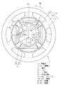
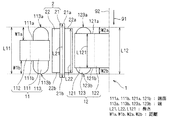
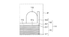
図1及び図2は、本発明にかかる回転電機1を概念的に示す。図1では、回転電機1の中心軸である所定の軸92に直交する断面が、図2では、図1に示される位置A−Aでの断面が、それぞれ示されている。
1. 1 and 2 conceptually show a rotating
回転電機1は、界磁子2と、電機子11,12とを備える。
The rotating
界磁子2は、所定の軸92の周りで環状を呈する。界磁子2は、コア22と磁石21とを有する。具体的には、コア22は、所定の軸92の周りで周方向95に沿って環状を呈する。磁石21は、コア22に設けられ、所定の軸92に沿って延在する。磁石21は、コア22に埋め込まれても良いし(図1及び図2)、コア22の電機子11,12側のそれぞれの表面の少なくともいずれか一方に設けられても良い。なお、界磁子2は、環状の磁石21のみで構成されても良い。
The
図1では、界磁子2の極数が4の場合が示されている。具体的には、4つの磁石21が所定の軸92の周りで環状に配置されている。磁石21はいずれも、電機子11,12側の表面のそれぞれに異なる極性を呈する。そして、周方向95に沿って隣接する磁石21同士は、電機子11側の表面に異なる極性を呈する。
In FIG. 1, the case where the number of poles of the
電機子11は、ティース111の複数、ヨーク112及び巻線113を有し、界磁子2の外周側に配置される。ヨーク112は、所定の軸92の周りで環状を呈する。
The
ティース111のそれぞれは、所定の軸92の周りで環状に配置され、ヨーク112に対して内周側から連結され、そして界磁子2に対して外周側から対向する。ティース111の各々は、端面111a,111bを有する。端面111a,111bはいずれも、所定の軸92に沿う方向を向いている。
Each of the
図2では、所定の軸92に沿って端面111aから端面111bへと向かう方向が一方向91として示されている。一方向91を用いて、端面111a,111bを次のように把握することができる。すなわち、端面111a,111bは、所定の軸92に沿う一方向91を向き、当該一方向91へと順に配置される。
In FIG. 2, the direction from the
巻線113は、ティース111のそれぞれに巻回され、端113a,113bを含む。端113a,113bは、一方向91について巻線113の外周側の端である。そして、端113aはティース111に対して端面111aと同じ側にあり、端113bはティース111に対して端面111bと同じ側にある。
Winding 113 is wound around each of
電機子12は、ティース121の複数、ヨーク122、巻線123を有し、界磁子2の内周側に配置される。ヨーク122は、所定の軸92の周辺に位置する。
The
ティース121のそれぞれは、所定の軸92の周りで環状に配置され、ヨーク122に対して外周側から連結され、そして界磁子2に対して内周側から対向する。ティース121の各々は、端面121a,121bを有する。端面121a,121bはいずれも、所定の軸92に沿う方向を向いている。
Each of the
端面111a,111bと同様に一方向91(図2)を用いて、端面121a,121bを次のように把握することができる。すなわち、端面121a,121bは、所定の軸92に沿う一方向91を向き、当該一方向91へと順に配置される。
Similarly to the
巻線123は、ティース121のそれぞれに巻回され、端123a,123bを含む。端123a,123bは、一方向91について巻線123の外周側の端である。そして、端123aはティース121に対して端面121aと同じ側にあり、端123bはティース121に対して端面121bと同じ側にある。
Winding 123 is wound around each of
ティース111への巻線113の巻き方、及びティース121への巻線123の巻き方のそれぞれには、集中巻や分布巻が採用できる。巻線113,123の接続には、直列接続や並列接続が採用できる。巻線113,123のそれぞれに3相電流が流れる場合には、巻線113,123の接続には、スター結線やデルタ結線などが採用できる。
Concentrated winding and distributed winding can be employed for winding the winding 113 around the
ティース111とティース121とは次のような関係にある。すなわち、端面111aは、端面121aに対して一方向91へと退いている。端面111bは、端面121bに対して一方向91とは反対方向へと退いている。
The
巻線113と巻線123とは次のような関係にある。すなわち、端113aと端面111aとの間の距離W1aは、端123aと端面121aとの間の距離W2aよりも大きい。また、端113bと端面111bとの間の距離W1bは、端123bと端面121bとの間の距離W2bよりも大きい。
The winding 113 and the winding 123 have the following relationship. That is, the distance W1a between the
上述した回転電機1によれば、端面111aが端面121aに対して一方向91へと退き、端面111bが端面121bに対して一方向91とは反対方向へと退いているので、電機子11の一方向91についての長さL11が大きくなることを抑制できる。よって、巻線113の巻数を巻線123の巻数よりも大きくしたり、巻線113を巻線123よりも太くしたりしても、回転電機1は大型化しない。すなわち、回転電機1の大型化を抑制しつつも、巻線123に比べて巻線113において多くの磁束を発生させて、回転電機1のトルクを高めることができる。
According to the rotating
なお、図1は、極数Pと、ティース111,121のそれぞれの本数Yとの組合せ(P,Y)が(4,6)の回転電機1を示しているが、組合せ(P,Y)には他の組合せを採用しても良く、上述した回転電機1と同様の効果が得られる。
1 shows the rotating
上述した回転電機1について、次の態様が望ましい。すなわち、一方向91について、巻線113の端113aの位置と、巻線123の端123aの位置とは略一致する。
About the rotary
さらには、一方向91について、巻線113の端113bの位置と、巻線123の端123bの位置とが略一致することが望ましい。
Furthermore, it is desirable that the position of the
かかる態様によれば、電機子11の長さL11と、電機子12の一方向91についての長さL12とをほぼ同じすることができる。よって、回転電機1が大型化することを抑制しつつも、回転電機1のトルクを大きくすることができる。
According to this aspect, the length L11 of the
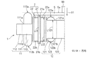
例えば、巻線113の端113aの位置は、巻線123の端123aの位置よりも一方向とは反対方向へとずれていても良い。かかる態様は図3に示されている。
For example, the position of the
図3に示される回転電機1は、回転軸99と端板5とを更に備える。端板5は、一方向91とは反対方向から電機子12に離間して被さる。界磁子2は、端板5を介して回転軸99に接続される。
The rotating
かかる態様によれば、一方向91について、巻線113の端113aの位置が、端板5の界磁子2とは反対側の端面5aの位置に略一致するまで、巻線113をティース111に巻回することができる。よって、回転電機1を顕著には大型化させずに、電機子11で発生する磁束を増大することでき、以って回転電機1のトルクを大きくすることができる。
According to this aspect, in one
同様に、巻線113の端113bの位置は、巻線123の端123bの位置よりも一方向へとずれていても良い。
Similarly, the position of the
2.ティースについて
図1では、ティース111の、内周側から外周側へと向かう方向に対する断面の面積S1が示されている。面積S1は、ティース111の当該断面の面積のうち最小のものである。また、ティース121の、内周側から外周側へと向かう方向に対する断面の面積S2も示されている。面積S2は、ティース121の当該断面の面積のうち最小のものである。
2. About Teeth FIG. 1 shows an area S1 of a cross section of the
図1に示されるように、面積S1は面積S2よりも大きいことが望ましい。例えば、面積S1の面積S2に対する比率が、所定の軸92から界磁子2の外周までの距離R1の、所定の軸92から界磁子2の内周までの距離R2に対する比率と略同一にされる。
As shown in FIG. 1, the area S1 is desirably larger than the area S2. For example, the ratio of the area S1 to the area S2 is substantially the same as the ratio of the distance R1 from the
かかる態様によれば、界磁子2の磁束について、ティース111に流れる鎖交磁束の磁束密度と、ティース121に流れる鎖交磁束の磁束密度とをほぼ同じすることができる。そして、磁石21を設けて得た界磁子2においては、電機子11,12のそれぞれの磁気抵抗をほぼ等しくすることで、磁石21の動作点が同じときに電機子11,12のそれぞれに流れる磁束の量を最大にすることができる。よって、回転電機1のトルクを大きくすることができる。
According to this aspect, with respect to the magnetic flux of the
具体的には、鎖交磁束の磁束密度を、ティース111とティース121とでほぼ同じにすることで、ティース111での磁気抵抗とティース121での磁気抵抗とをほぼ同じにすることができる。
Specifically, by making the magnetic flux density of the interlinkage magnetic flux substantially the same between the
例えば、ティース111,121のいずれか一方の磁気抵抗が他方の磁気抵抗よりも大きくなると、当該一方では磁束の流れが阻害される。これにより、当該他方での磁束の流れも阻害される。
For example, when the magnetic resistance of one of the
しかし、上述のようにティース111,121の磁気抵抗をほぼ同じにすることで、磁束の流れが阻害されにくくなる。よって、回転電機1の効率が低下することが防止される。
However, by making the magnetic resistances of the
かかる効果は、コア22の電機子11,12側のそれぞれの表面に磁石21が設けて得た界磁子2において、特に顕著に現れる。
Such an effect is particularly prominent in the
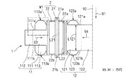
図4は、図1で示される位置A−Aでの回転電機1の断面であって、ティース111及びティース121の形状を概念的に示す。
FIG. 4 is a cross section of the rotating
ティース111は、外周側から内周側へと向かう方向93に対する断面が、当該方向93に行くに従って拡がる。かかる形状によれば、界磁子2から流れる磁束の多くをティース111に導くことができる。
In the
しかも、電機子11と界磁子2との間のエアギャップの面積が増大するので、当該エアギャップの磁気抵抗が低減する。磁石21を設けて得た界磁子2においては、磁石21の動作点を高めることで磁石21で発生する磁束を増大させ、巻線113,123に多くの磁束を鎖交させることができる。よって、回転電機1のトルクを大きくすることができる。
In addition, since the area of the air gap between the
ティース121は、内周側から外周側へと向かう方向94に対する断面が、当該方向94に行くに従って拡がる。かかる形状によれば、界磁子2から流れる磁束の多くをティース121に導くことができる。しかも、上述したのと同様に、電機子12と界磁子2との間のエアギャップの磁気抵抗が低減する。
In the
かかる形状を有するティース111の構造について、より具体的に図5を用いて説明する。図5は、図4で一点鎖線で囲まれた領域W1を拡大して示す。なお、ティース121についてもティース111と同様である。
The structure of the
ティース111は、磁性体51,52を有する。磁性体51は、自身が属するティース111が突出する方向93と同じ方向へと、ヨーク112から延びる。
The
磁性体52は、磁性体51の方向91についての一端51aに設けられる。磁性体52は、磁性体51の方向91についての他端51bにも設けることができる。
The
磁性体52は一体であって、根部521と鍔部522とを含む。根部521は、自身が属するティース111が突出する方向93と同じ方向へとヨークから延びる。
The
鍔部522は、根部521のヨーク112とは反対側の端から、磁性体51とは反対側へと延びる。図5では、鍔部522は方向91に沿って延びている。
The
かかる態様によれば、磁性体52は一体であるので、例えば板状の磁性体52を折り曲げるだけで根部521と鍔部522とを成形することができ、以ってティース111の成形が容易である。
According to this aspect, since the
磁性体51は、方向91に積層された複数の磁性体板511を有しても良い。かかる磁性体51によれば、鉄損を低減できる。
The
3.界磁子について
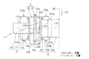
図2乃至図4では、磁石21の一方向91についての長さL21は、ティース121の一方向91についての長さL121よりも大きい。
3. Regarding the Field Element In FIGS. 2 to 4, the length L <b> 21 in one
かかる態様によれば、磁石21の磁極面積を大きくすることで、巻線113,123に多くの磁束を鎖交させることができ、以って回転電機1のトルクを大きくすることができる。
According to this aspect, by increasing the magnetic pole area of the
また、長さL21は、コア22の一方向91についての長さL22よりも大きい(図2乃至図4)。かかる態様によれば、磁石21の一方向91についての端21a,21bの少なくとも一方がコア22から突出する。磁石21の突出した部分で生じた磁束は、磁気抵抗の低いコア22へと導かれる。よって、突出した端21a,21bで、磁石21の磁極面の一方から他方へと磁束が短絡することが防止される。なお、図2乃至図4では、端21a,21bのいずれもがコア22から突出している場合が示されている。
Further, the length L21 is larger than the length L22 in one
図2乃至図4ではさらに、コア22の長さL22が、ティース121の長さL121よりも大きい場合が示されている。かかる態様によれば、電機子12と界磁子2との間のエアギャップの面積が増大するので、当該エアギャップの磁気抵抗が低減する。そして、磁石21を設けて得た界磁子2においては、磁石の動作点を高めることで、巻線113,123に磁石21の磁束の多くを鎖交させることができる。よって、回転電機1のトルクを大きくすることができる。
2 to 4 further show a case where the length L22 of the
図6は、図1で示される位置A−Aでの回転電機1の断面であって、界磁子2の形状を概念的に示す。
FIG. 6 is a cross section of the rotating
ティース111は、界磁子2側から見た中心を位置r11に有する。ティース121は、界磁子2側から見た中心を位置r12に有する。
The
界磁子2は、一方向91について、位置r11または位置r12と同じ位置r2からの、コア22の一端22aまでの距離L22aと、他端22bまでの距離L22bとが異なる。具体的に図6では、距離L22bが距離L22aよりも大きい。なお、図6では、一方向91について位置r11と位置r12とが一致している場合が示されている。
In the
かかる回転子2の形状によれば、回転電機1を駆動する際に必要なスラスト力を発生させることができる。
According to the shape of the
例えば、一方向91について、界磁子2の中心の位置を、ティース111またはティース121の中心の位置r11,r12から、一方向91またはそれとは反対方向へと変位させることでも、界磁子2において位置r2からの距離L22aと距離L22bとを異ならせることができる。このとき、以下に説明するように、ティース111,121に対する界磁子2の変位の大きさが小さくても、必要なスラスト力を発生させることができる。
For example, the
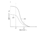
図7は、ティース111,121に対する界磁子2の変位の大きさ(以下、単に「変位」という。)x(横軸)と、エアギャップに蓄えられる磁気エネルギーWg(縦軸)との関係を示す。変位xを値x1まで大きくしても、磁気エネルギーWgはほとんど低下しない。これは、エアギャップの磁束密度がほとんど低下しないからである。変位xが値x1から値x2の範囲にある場合には、変位xが大きくなるに従って磁気エネルギーWgは顕著に低下する。そして、変位xが値x2からさらに大きくなるに従って磁気エネルギーWgは0に漸近する。
FIG. 7 shows the relationship between the magnitude of displacement of the
スラスト力は、変位xの関数として表された磁気エネルギーWgを、変位xで微分して得られる。 The thrust force is obtained by differentiating the magnetic energy Wg expressed as a function of the displacement x by the displacement x.
図7では、電機子が一つだけ設けられた回転電機の、変位xと磁気エネルギーWgとの関係を破線201で示している。当該回転電機では、磁気エネルギーWgの変位xに対する変化量(変位xでの微分)が、回転電機1よりも小さいことがわかる。すなわち、変位xが値x1から値x2の間にある場合には、回転電機1の方が、変位xの変化量が小さくても磁気エネルギーWgの変化量は大きく、以ってスラスト力は顕著に変化する。
In FIG. 7, the relationship between the displacement x and the magnetic energy Wg of a rotating electrical machine provided with only one armature is indicated by a
スラスト力は、回転電機1の一方向91についての振動を抑制することができる。例えば、よって、回転電機1を圧縮機などに搭載した場合には振動による騒音が低減できる。また、回転電機1をDVD(Digital Versatile Disk)等の再生機やレコーダなどに搭載して、アクチュエータとして用いた場合には、読取りや書込みのエラーを低減することができる。
The thrust force can suppress vibration in one
ただし、図7に示される関係からもわかるように、変位xを顕著に大きくすると磁気エネルギーWgが小さくなり、以って回転電機1に流れる磁束の量も小さくなる。よって、変位xは、回転電機1に必要な磁束量とスラスト力の両方を考慮して選択することが望ましい。
However, as can be seen from the relationship shown in FIG. 7, when the displacement x is remarkably increased, the magnetic energy Wg is reduced, and the amount of magnetic flux flowing through the rotating
上述した回転電機1はいずれも、例えば冷媒を圧縮する圧縮機や、送風を行う送風機などに搭載することができる。また、かかる圧縮機や送風機は、空気調和機に搭載することができる。特に車載用の空気調和機では、自身に搭載する回転電機を小型化する必要があり、本発明にかかる回転電機1を採用することが望ましい。
Any of the above-described rotating
回転電機1は、例えば発電機として駆動することもできる。
The rotating
4.その他の態様
なお、上述した回転電機1とは異なり、例えば端面111aを端面121aに対して一方向91とは反対方向へと突出させても良いし、端面111bを端面121bに対して一方向91へと突出させても良い。
4). Other Embodiments Unlike the rotating
2 界磁子
11,12 電機子
21 磁石
22 コア
91 一方向
92 所定の軸
111,112 ティース
111a,111b,121a,121b 端面
113,123 巻線
113a,113b,123a,123b 端
S1,S2 面積
R1,R2,L22a,L22b 距離
L21,L22,L121 長さ
r11,r12,r2 位置
W1a,W1b,W2a,W2b 距離
2
Claims (15)
前記界磁子の外周側に配置される第1の電機子(11)と、
前記界磁子の内周側に配置される第2の電機子(12)と
を備え、
前記第1の電機子は、
前記所定の軸の周りで環状に配置され、それぞれ界磁子に外周側から対向する第1のティース(111)の複数と、
前記第1のティースのそれぞれに巻回される第1の巻線(113)と
を有し、
前記第1のティースは、
前記所定の軸に沿う一方向(91)を向き、前記一方向へと順に配置される第1及び第2の端面(111a,111b)
を含み、
前記第2の電機子は、
前記所定の軸の周りで環状に配置され、それぞれ界磁子に内周側から対向する第2のティース(121)の複数と、
前記第2のティースのそれぞれに巻回される第2の巻線(123)と
を有し、
前記第2のティースは、
前記一方向を向き、前記一方向へと順に配置される第3及び第4の端面(121a,121b)
を含み、
前記第1の端面は、前記第3の端面に対して前記一方向へと退き、
前記第2の端面は、前記第4の端面に対して前記一方向とは反対方向へと退き、
前記一方向について、前記第1の巻線の外周側の端(113a,113b)のうち前記第1のティースに対して前記第1の端面(111a)と同じ側にある第1の端(113a)と、当該第1の端面との間の距離である第1の距離(W1a)は、前記第2の巻線の外周側の端(123a,123b)のうち前記第2のティースに対して前記第3の端面(121a)と同じ側にある第2の端(123a)と、当該第3の端面との間の距離である第2の距離(W2a)よりも大きい、
回転電機。 A field element (2) presenting an annulus about a predetermined axis (92);
A first armature (11) disposed on the outer peripheral side of the field element;
A second armature (12) disposed on the inner peripheral side of the field element,
The first armature is:
A plurality of first teeth (111) arranged in a ring around the predetermined axis, each facing the field element from the outer peripheral side;
A first winding (113) wound around each of the first teeth,
The first teeth are
First and second end faces (111a, 111b) arranged in this direction in a direction (91) along the predetermined axis.
Including
The second armature is
A plurality of second teeth (121) arranged in a ring around the predetermined axis, each facing the field element from the inner peripheral side;
A second winding (123) wound around each of the second teeth,
The second tooth is
Third and fourth end faces (121a, 121b) that face in the one direction and are sequentially arranged in the one direction
Including
The first end surface retracts in the one direction with respect to the third end surface;
The second end surface retracts in a direction opposite to the one direction with respect to the fourth end surface;
A first end (113a) on the same side as the first end surface (111a) with respect to the first tooth among the ends (113a, 113b) on the outer peripheral side of the first winding in the one direction. ) And the first end face is a first distance (W1a) with respect to the second teeth among the outer ends (123a, 123b) of the second winding. A second end (123a) on the same side as the third end face (121a) and a second distance (W2a) that is a distance between the third end face;
Rotating electric machine.
前記一方向について、前記磁石の長さ(L21)は前記第2のティース(121)の長さ(L121)よりも大きい、
請求項1乃至請求項6のいずれか一つに記載の回転電機。 The field element (2) has a magnet (21) extending in the one direction (91),
With respect to the one direction, the length (L21) of the magnet is larger than the length (L121) of the second tooth (121).
The rotating electrical machine according to any one of claims 1 to 6.
前記一方向について、前記コアの長さ(L22)は前記第2のティース(121)の長さ(L121)よりも大きい、
請求項1乃至請求項7のいずれか一つに記載の回転電機。 The field element (2) has a core (22) presenting a ring around the predetermined axis (92);
About the said one direction, the length (L22) of the said core is larger than the length (L121) of the said 2nd teeth (121),
The rotating electrical machine according to any one of claims 1 to 7.
前記一方向について、前記磁石の長さ(L21)は前記コアの長さ(L22)よりも大きい、
請求項8記載の回転電機。 The field element (2) further includes a magnet (21) provided in the core (22) and extending in the one direction (91),
In the one direction, the magnet length (L21) is larger than the core length (L22),
The rotating electrical machine according to claim 8.
前記コアは、前記一方向(91)について、前記第1または前記第2のティース(111,121)の界磁子側から見た中心の位置(r11,r12)と同じ位置(r2)からの、前記コアの一端(22a)までの距離(L22a)と、他端(22b)までの距離(L22b)とが異なる、
請求項1乃至請求項9のいずれか一つに記載の回転電機。 The field element (2) has a core (22) presenting a ring around the predetermined axis (92);
The core from the same position (r2) as the center position (r11, r12) viewed from the field element side of the first or second teeth (111, 121) in the one direction (91). The distance (L22a) to one end (22a) of the core is different from the distance (L22b) to the other end (22b).
The rotating electrical machine according to any one of claims 1 to 9.
Priority Applications (2)
| Application Number | Priority Date | Filing Date | Title |
|---|---|---|---|
| JP2006310161A JP5194436B2 (en) | 2006-11-16 | 2006-11-16 | Rotating electric machine, compressor, blower, air conditioner |
| PCT/JP2007/072187 WO2008059923A1 (en) | 2006-11-16 | 2007-11-15 | Rotating electric machine, compressor, fan, and air conditioner |
Applications Claiming Priority (1)
| Application Number | Priority Date | Filing Date | Title |
|---|---|---|---|
| JP2006310161A JP5194436B2 (en) | 2006-11-16 | 2006-11-16 | Rotating electric machine, compressor, blower, air conditioner |
Publications (2)
| Publication Number | Publication Date |
|---|---|
| JP2008131663A true JP2008131663A (en) | 2008-06-05 |
| JP5194436B2 JP5194436B2 (en) | 2013-05-08 |
Family
ID=39401727
Family Applications (1)
| Application Number | Title | Priority Date | Filing Date |
|---|---|---|---|
| JP2006310161A Expired - Fee Related JP5194436B2 (en) | 2006-11-16 | 2006-11-16 | Rotating electric machine, compressor, blower, air conditioner |
Country Status (2)
| Country | Link |
|---|---|
| JP (1) | JP5194436B2 (en) |
| WO (1) | WO2008059923A1 (en) |
Cited By (3)
| Publication number | Priority date | Publication date | Assignee | Title |
|---|---|---|---|---|
| JP2010114959A (en) * | 2008-11-04 | 2010-05-20 | Toyota Central R&D Labs Inc | Power transmitter |
| WO2014109218A1 (en) * | 2013-01-10 | 2014-07-17 | 株式会社Ihi | Double stator switched reluctance rotating machine |
| US9692267B2 (en) | 2012-12-28 | 2017-06-27 | Ihi Corporation | Double stator switched reluctance rotating machine |
Citations (3)
| Publication number | Priority date | Publication date | Assignee | Title |
|---|---|---|---|---|
| JPH02254952A (en) * | 1989-03-28 | 1990-10-15 | Mitsubishi Electric Corp | Motor |
| JP2004260970A (en) * | 2003-02-27 | 2004-09-16 | Toyota Motor Corp | Electric motor and electric motor system |
| WO2006092924A1 (en) * | 2005-02-28 | 2006-09-08 | Daikin Industries, Ltd. | Magnetic body, rotor, motor, compressor, fan, air conditioner, and on-vehicle air conditioner |
-
2006
- 2006-11-16 JP JP2006310161A patent/JP5194436B2/en not_active Expired - Fee Related
-
2007
- 2007-11-15 WO PCT/JP2007/072187 patent/WO2008059923A1/en not_active Ceased
Patent Citations (3)
| Publication number | Priority date | Publication date | Assignee | Title |
|---|---|---|---|---|
| JPH02254952A (en) * | 1989-03-28 | 1990-10-15 | Mitsubishi Electric Corp | Motor |
| JP2004260970A (en) * | 2003-02-27 | 2004-09-16 | Toyota Motor Corp | Electric motor and electric motor system |
| WO2006092924A1 (en) * | 2005-02-28 | 2006-09-08 | Daikin Industries, Ltd. | Magnetic body, rotor, motor, compressor, fan, air conditioner, and on-vehicle air conditioner |
Cited By (5)
| Publication number | Priority date | Publication date | Assignee | Title |
|---|---|---|---|---|
| JP2010114959A (en) * | 2008-11-04 | 2010-05-20 | Toyota Central R&D Labs Inc | Power transmitter |
| US9692267B2 (en) | 2012-12-28 | 2017-06-27 | Ihi Corporation | Double stator switched reluctance rotating machine |
| WO2014109218A1 (en) * | 2013-01-10 | 2014-07-17 | 株式会社Ihi | Double stator switched reluctance rotating machine |
| JP5867628B2 (en) * | 2013-01-10 | 2016-02-24 | 株式会社Ihi | Double stator type switched reluctance rotating machine |
| US9647520B2 (en) | 2013-01-10 | 2017-05-09 | Ihi Corporation | Double stator switched reluctance rotating machine |
Also Published As
| Publication number | Publication date |
|---|---|
| WO2008059923A1 (en) | 2008-05-22 |
| JP5194436B2 (en) | 2013-05-08 |
Similar Documents
| Publication | Publication Date | Title |
|---|---|---|
| CN101803157B (en) | Permanent magnet rotating machine | |
| CN106877615B (en) | Motor and electric device having the same mounted thereon | |
| JP4737193B2 (en) | Rotor, electric motor, compressor, blower, air conditioner and in-vehicle air conditioner | |
| JP5359192B2 (en) | Anisotropic permanent magnet motor | |
| JP2014155373A (en) | Multi-gap rotary electric machine | |
| JP5248751B2 (en) | Slotless permanent magnet type rotating electrical machine | |
| JP5381139B2 (en) | Electric motor | |
| CN107078617A (en) | Bimorph transducer type circulator | |
| KR101842827B1 (en) | Double Stator Axial Field Type Switched Reluctance Motor | |
| JP5194436B2 (en) | Rotating electric machine, compressor, blower, air conditioner | |
| US9018815B2 (en) | Generator | |
| JP4848670B2 (en) | Rotor, electric motor, compressor, blower, and air conditioner | |
| JP4791325B2 (en) | Synchronous motor, air conditioner and ventilation fan | |
| JP2010142000A (en) | Stator core, stator and axial type motor | |
| JPWO2011036723A1 (en) | Synchronous generator | |
| KR20230084855A (en) | Afpm motor with rfpm motor structure applied | |
| JP2009201236A (en) | Electric motor and method for fixing stator of the electric motor | |
| CN114337023A (en) | Rotating electrical machine | |
| US20250392177A1 (en) | Rotor and electric machine | |
| JP2007166798A (en) | Rotating electric machine, compressor, blower, and air conditioner | |
| JP2019162005A (en) | Brushless motor, and blower | |
| JP2007116850A (en) | Permanent magnet rotating electrical machine and cylindrical linear motor | |
| CN105634167A (en) | Motor | |
| JP4607823B2 (en) | AC rotating electric machine | |
| JP5401753B2 (en) | Rotating electric machine |
Legal Events
| Date | Code | Title | Description |
|---|---|---|---|
| A621 | Written request for application examination |
Free format text: JAPANESE INTERMEDIATE CODE: A621 Effective date: 20090925 |
|
| A131 | Notification of reasons for refusal |
Free format text: JAPANESE INTERMEDIATE CODE: A131 Effective date: 20120117 |
|
| A521 | Written amendment |
Free format text: JAPANESE INTERMEDIATE CODE: A523 Effective date: 20120314 |
|
| TRDD | Decision of grant or rejection written | ||
| A01 | Written decision to grant a patent or to grant a registration (utility model) |
Free format text: JAPANESE INTERMEDIATE CODE: A01 Effective date: 20130108 |
|
| A61 | First payment of annual fees (during grant procedure) |
Free format text: JAPANESE INTERMEDIATE CODE: A61 Effective date: 20130121 |
|
| FPAY | Renewal fee payment (event date is renewal date of database) |
Free format text: PAYMENT UNTIL: 20160215 Year of fee payment: 3 |
|
| FPAY | Renewal fee payment (event date is renewal date of database) |
Free format text: PAYMENT UNTIL: 20160215 Year of fee payment: 3 |
|
| LAPS | Cancellation because of no payment of annual fees |