JP2008123982A - Illumination device and luminance switching device of illumination device - Google Patents
Illumination device and luminance switching device of illumination device Download PDFInfo
- Publication number
- JP2008123982A JP2008123982A JP2007015427A JP2007015427A JP2008123982A JP 2008123982 A JP2008123982 A JP 2008123982A JP 2007015427 A JP2007015427 A JP 2007015427A JP 2007015427 A JP2007015427 A JP 2007015427A JP 2008123982 A JP2008123982 A JP 2008123982A
- Authority
- JP
- Japan
- Prior art keywords
- luminance
- led
- light source
- changeover switch
- switching
- Prior art date
- Legal status (The legal status is an assumption and is not a legal conclusion. Google has not performed a legal analysis and makes no representation as to the accuracy of the status listed.)
- Pending
Links
Images

Classifications
-
- H—ELECTRICITY
- H05—ELECTRIC TECHNIQUES NOT OTHERWISE PROVIDED FOR
- H05B—ELECTRIC HEATING; ELECTRIC LIGHT SOURCES NOT OTHERWISE PROVIDED FOR; CIRCUIT ARRANGEMENTS FOR ELECTRIC LIGHT SOURCES, IN GENERAL
- H05B45/00—Circuit arrangements for operating light-emitting diodes [LED]
- H05B45/10—Controlling the intensity of the light
-
- F—MECHANICAL ENGINEERING; LIGHTING; HEATING; WEAPONS; BLASTING
- F21—LIGHTING
- F21S—NON-PORTABLE LIGHTING DEVICES; SYSTEMS THEREOF; VEHICLE LIGHTING DEVICES SPECIALLY ADAPTED FOR VEHICLE EXTERIORS
- F21S2/00—Systems of lighting devices, not provided for in main groups F21S4/00 - F21S10/00 or F21S19/00, e.g. of modular construction
- F21S2/005—Systems of lighting devices, not provided for in main groups F21S4/00 - F21S10/00 or F21S19/00, e.g. of modular construction of modular construction
-
- H—ELECTRICITY
- H05—ELECTRIC TECHNIQUES NOT OTHERWISE PROVIDED FOR
- H05B—ELECTRIC HEATING; ELECTRIC LIGHT SOURCES NOT OTHERWISE PROVIDED FOR; CIRCUIT ARRANGEMENTS FOR ELECTRIC LIGHT SOURCES, IN GENERAL
- H05B45/00—Circuit arrangements for operating light-emitting diodes [LED]
- H05B45/30—Driver circuits
- H05B45/37—Converter circuits
- H05B45/3725—Switched mode power supply [SMPS]
-
- F—MECHANICAL ENGINEERING; LIGHTING; HEATING; WEAPONS; BLASTING
- F21—LIGHTING
- F21Y—INDEXING SCHEME ASSOCIATED WITH SUBCLASSES F21K, F21L, F21S and F21V, RELATING TO THE FORM OR THE KIND OF THE LIGHT SOURCES OR OF THE COLOUR OF THE LIGHT EMITTED
- F21Y2115/00—Light-generating elements of semiconductor light sources
- F21Y2115/10—Light-emitting diodes [LED]
-
- Y—GENERAL TAGGING OF NEW TECHNOLOGICAL DEVELOPMENTS; GENERAL TAGGING OF CROSS-SECTIONAL TECHNOLOGIES SPANNING OVER SEVERAL SECTIONS OF THE IPC; TECHNICAL SUBJECTS COVERED BY FORMER USPC CROSS-REFERENCE ART COLLECTIONS [XRACs] AND DIGESTS
- Y02—TECHNOLOGIES OR APPLICATIONS FOR MITIGATION OR ADAPTATION AGAINST CLIMATE CHANGE
- Y02B—CLIMATE CHANGE MITIGATION TECHNOLOGIES RELATED TO BUILDINGS, e.g. HOUSING, HOUSE APPLIANCES OR RELATED END-USER APPLICATIONS
- Y02B20/00—Energy efficient lighting technologies, e.g. halogen lamps or gas discharge lamps
- Y02B20/30—Semiconductor lamps, e.g. solid state lamps [SSL] light emitting diodes [LED] or organic LED [OLED]
Landscapes
- Engineering & Computer Science (AREA)
- General Engineering & Computer Science (AREA)
- Led Devices (AREA)
- Circuit Arrangement For Electric Light Sources In General (AREA)
- Non-Portable Lighting Devices Or Systems Thereof (AREA)
- Control Of Indicators Other Than Cathode Ray Tubes (AREA)
Abstract
Description
本発明は、照明デバイス及び照明デバイスの輝度切替デバイスに関し、より具体的には、様々な照明デバイスの多段階切り替えを提供するための内蔵型記憶ユニットを有する輝度切替デバイスに関する。 The present invention relates to a lighting device and a luminance switching device of the lighting device, and more particularly to a luminance switching device having a built-in storage unit for providing multi-stage switching of various lighting devices.
近年、日常生活において、例えば、モニタ、家庭用電気製品、車両用電子コンポーネント、照明ランプといったものに、発光ダイオード(LED)が広く使用されている。家庭用照明ランプを例に取ると、従来の家庭用照明ランプは通常複数の電球を有し、ユーザが環境の輝度状態を変更したい時は、電球をオフするように、切替スイッチを使用して、設定された値に従って多段階で複数の電球を連続的に切り替える。例えば、切替スイッチがちょうどオンされた時は、全ての電球がオンの状態になる。切替スイッチがオフされて、再びオンされた時は、少なくとも1つの電球がオフ状態になり、結果として照明ランプ全体によって発せられる光の輝度が弱化する。切替スイッチがオフされて、再びオンされた時は、前段階においてオン状態にある少なくとも1つの電球がオフ状態を取る。従って、照明ランプの輝度を多段階で切り替えることができる。しかしながら、照明ランプの電球がLEDによって置き換えられると、電球において要求されるLEDのユニット数が大きいので、もし上記した動作モードに従って照明ランプのLEDが連続的にオフされれば、照明ランプ全体から発せられる光の輝度は不均一になる。 In recent years, light-emitting diodes (LEDs) have been widely used in daily life, for example, in monitors, household appliances, vehicle electronic components, illumination lamps, and the like. Taking home lighting lamps as an example, conventional home lighting lamps usually have multiple light bulbs, and when the user wants to change the brightness state of the environment, use a changeover switch to turn off the light bulbs. , Switch multiple bulbs continuously in multiple stages according to the set value. For example, when the changeover switch is just turned on, all the light bulbs are turned on. When the changeover switch is turned off and turned on again, at least one light bulb is turned off, resulting in a decrease in the brightness of the light emitted by the entire illumination lamp. When the changeover switch is turned off and turned on again, at least one light bulb that is on in the previous stage takes off. Therefore, the brightness of the illumination lamp can be switched in multiple stages. However, if the bulb of the illumination lamp is replaced by an LED, the number of LED units required in the bulb is large, so if the LED of the illumination lamp is turned off continuously according to the above operation mode, the whole illumination lamp emits light. The brightness of the emitted light is non-uniform.
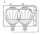
光源としてLEDを使用するデバイスの不均一な輝度の上述した問題を解決するために、米国特許第6,344,641号は、光源としてLEDを使用する表示システムの制御方法を開示している。図1は、従来の表示システムの概略図である。図1を参照すると、従来の表示システム10は2つのLED12A及び12B、表示デバイス14、及び表示デバイス14に配置された輝度検出及び制御回路20を含む。表示デバイス14は、画像表示アレイ18を含み、表示デバイス14の画像を表示する。加えて、表示デバイス14は、輝度検出及び制御回路20に電気的に接続された、タイミング及び制御信号を輝度検出及び制御回路20に送信するためのコントローラ22を更に含む。2つの光検出器16A及び16Bは、LED12A及び12Bと一直線上にあり、LED12A及び12Bそれぞれによって発せられる光の輝度を検出するために、輝度検出及び制御回路20に電気的に接続されている。
In order to solve the above-mentioned problem of non-uniform brightness of devices that use LEDs as light sources, US Pat. No. 6,344,641 discloses a method for controlling a display system that uses LEDs as light sources. FIG. 1 is a schematic diagram of a conventional display system. Referring to FIG. 1, a
光検出器16A及び16BがLED12A及び12Bそれぞれによって発せられた光の輝度を検出した時、光の検出された輝度は電流信号に変換されて、輝度検出及び制御回路20に送信される。この時、もしLED12A及び12Bの輝度が変更される必要がある場合、制御器22はユーザの要求に従って輝度検出及び制御回路20に変調信号を出力する。そして、輝度検出及び制御回路20は、光検出器16A及び16B及びコントローラ22からの信号を統合して、電圧信号を送信してLED12A及び12Bの調節すべき輝度をそれぞれ変調する。従って、表示デバイス14のLED12A及び12Bによって発せられる光の輝度の制御が実現する。
When the
しかしながら、輝度検出及び制御回路20はLED12A及び12Bが個々に発する光の輝度を制御するが、光検出器16A及び16Bによって検出されたLED12A及び12Bの不十分な輝度又は調節すべき輝度に従って補正のみを行うことができる。もしユーザがLED12A及び12Bによって発せられる光の輝度を異なる状態の輝度に個々に調節したい場合、表示デバイス14は、異なる明るさを示すようにLED12A及び12Bを使用する。光検出器16A及び16Bは隣接するLED12A及び12Bによって発せられる光によって影響されるので、例えば、光検出器16AはLED12Bによって発せられた光も検出するため、LED12A及び12Bを制御して異なる輝度の光を発するという目的が達成できない。更に、表示デバイス14が大量のLEDを使用する際、同時に不均一な輝度の問題を防止しながら、特定の状態において輝度検出及び制御回路20はLEDによって再び発せられる異なる輝度の光を制御することはできない。
However, the brightness detection and
上述の問題を鑑み、本発明の目的は、少なくとも1つのLEDによって構成されるLED光源によって生成される複数の発光状態の輝度を切り替えるための輝度切替デバイスを提供することである。輝度切替デバイスは、輝度切替デバイスに電気的に接続された、LEDの発光状態を切り替えるための切替スイッチであり、発光状態に対応する複数の切替モードを有する切替スイッチと、切替スイッチに電気的に接続された、切替スイッチの切替モードを検出するための検出回路と、検出回路に電気的に接続された記憶ユニットであり、検出回路によって検出された切替スイッチの切替モードに対応するLEDの輝度値を記憶し、そのLEDの輝度値を輝度制御信号に変換し、その輝度制御信号を検出回路に送信するための記憶ユニットと、LED光源に電気的に接続された電力変換回路であり、検出回路から送信された輝度制御信号を受信し、LED光源が切替モードに対応する発光状態の輝度を生成するようにするための電力変換回路と、を含む。 In view of the above problems, an object of the present invention is to provide a brightness switching device for switching the brightness of a plurality of light emitting states generated by an LED light source configured by at least one LED. The luminance switching device is a changeover switch that is electrically connected to the luminance changeover device and switches the light emission state of the LED. The changeover switch has a plurality of changeover modes corresponding to the light emission state, and is electrically connected to the changeover switch. A detection circuit for detecting the switching mode of the changeover switch, and a storage unit electrically connected to the detection circuit, and the luminance value of the LED corresponding to the changeover mode of the changeover switch detected by the detection circuit A storage unit for converting the luminance value of the LED into a luminance control signal and transmitting the luminance control signal to the detection circuit, and a power conversion circuit electrically connected to the LED light source, the detection circuit The power conversion circuit for receiving the luminance control signal transmitted from the LED light source and generating the luminance of the light emitting state corresponding to the switching mode , Including the.
更に、本発明は、少なくとも1つの発光ダイオード(LED)から構成された、複数の発光状態を有するLED光源と、LED光源の発光状態を切替るための、発光状態に対応する複数の切替モードを有する切替スイッチと、切替スイッチに電気的に接続された、切替スイッチの切替モードを検出するための検出回路と、検出回路に電気的に接続された記憶ユニットであり、検出回路によって検出された切替スイッチの切替モードに対応するLED光源のLEDの輝度値を記憶し、そのLEDの輝度値を輝度制御信号に変換し、その輝度制御信号を検出回路に送信するための記憶ユニットと、LED光源に電気的に接続された電力変換回路であり、検出回路から送信された輝度制御信号を受信し、LEDが切替モードに対応する発光状態の輝度を生成するようにするための電力変換回路とからなる照明デバイスも提供する。 Furthermore, the present invention includes an LED light source having a plurality of light emission states, which is composed of at least one light emitting diode (LED), and a plurality of switching modes corresponding to the light emission states for switching the light emission states of the LED light sources. A changeover switch, a detection circuit electrically connected to the changeover switch for detecting a changeover mode of the changeover switch, and a storage unit electrically connected to the detection circuit, the changeover detected by the detection circuit A storage unit for storing the LED brightness value of the LED light source corresponding to the switch mode, converting the LED brightness value into a brightness control signal, and transmitting the brightness control signal to the detection circuit; and the LED light source This is an electrically connected power conversion circuit that receives the brightness control signal transmitted from the detection circuit, and the LED emits light in the light emitting state corresponding to the switching mode. Lighting device comprising a power conversion circuitry to generate a also provided.
即ち、本願の第1発明は、少なくとも1つの発光ダイオード(LED)から構成されるLED光源であり、複数の発光状態を有するLED光源と、LED光源の発光状態を切り替えるための切替スイッチであり、発光状態に対応する複数の切り替えモードを有する切替スイッチと、切替スイッチに電気的に接続された、切替スイッチの切替モードを検出するための検出回路と、検出回路に電気的に接続された記憶ユニットであり、検出回路によって検出された切替スイッチの切替モードに対応するLED光源のLEDの輝度値を記憶し、そのLEDの輝度値を輝度制御信号に変換し、その輝度制御信号を検出回路に送信するための記憶ユニットと、LED光源に電気的に接続された電力変換回路であり、検出回路から送信された輝度制御信号を受信し、LEDが切替モードに対応する発光状態の輝度を生成するようにするための電力変換回路と、を備える、照明デバイスを提供する。
本願の第2発明は、LED光源の少なくとも1つのLEDの輝度は、切替スイッチの異なる切替モード下で異なる、第1発明の照明デバイスを提供する。
本願の第3発明は、切替スイッチの切り替えを通して照明デバイスに電力を提供するための外部電源を備える、第1発明の照明デバイスを提供する。
本願の第4発明は、LED光源に電気的に接続された、LED光源に電力を提供するための直流(DC)電源を備える、第1発明の照明デバイスを提供する。
本願の第5発明は、検出回路が、LED光源の発光状態を受信するための前方入力端を有し、且つ切替スイッチに電気的に接続された、切替スイッチの切替モードを受信するための後方入力端を有する増幅器と、増幅器及び記憶ユニットに電気的に接続された、増幅器及び記憶ユニットから送信されたアナログ制御信号をデジタル制御信号に変換するためにアナログ/デジタル変換回路と、を備える、第1発明の照明デバイスを提供する。
本願の第6発明は、切替スイッチが外部トリガー信号を通してLED光源の切替モードを行う、第2発明の照明デバイスを提供する。
本願の第7発明は、外部トリガー信号は連続する押圧信号であり、LED光源のLEDの輝度値は切替スイッチが押圧される時間に正比例又は反比例する、第6発明の照明デバイスを提供する。
本願の第8発明は、外部トリガー信号は多段階切替信号であり、LED光源のLEDの輝度値は切替スイッチが切り替えられる回数に従って多段階で増加又は多段階で減少する、第6発明の照明デバイスを提供する。
本願の第9発明は、外部トリガー信号は多段階押圧信号であり、切替モード間に所定の時間間隔が存在し、LED光源のLEDの輝度値は切替スイッチが切り替えられる時に従って多段階で増加又は多段階で減少する、第6発明の照明デバイスを提供する。
本願の第10発明は、外部トリガー信号を受信するための信号入力端を備える、第6発明の照明デバイスを提供する。
本願の第11発明は、切替スイッチはプログラマブル回路である、第1発明の照明デバイスを提供する。
本願の第12発明は、電力変換回路は交流(AC)/直流(DC)変換器である、第1発明の照明デバイスを提供する。
本願の第13発明は、電力変換回路はDC/DC変換器である、第1発明の照明デバイスを提供する。
本願の第14発明は、電力変換回路から出力される輝度制御信号はパルス幅変調(PWM)信号である、第1発明の照明デバイスを提供する。
本願の第15発明は、電力変換回路から出力される輝度制御信号は電圧信号である、第1発明の照明デバイスを提供する。
本願の第16発明は、電力変換回路から出力される輝度制御信号は電流信号である、第1発明の照明デバイスを提供する。
本願の第17発明は、少なくとも1つのLEDを含む発光ダイオード(LED)光源によって生成される複数の発光状態の輝度を切り替えるための輝度切替デバイスであって、当該輝度切替デバイスは、輝度切替デバイスに電気的に接続された、LEDの発光状態を切り替えるための切替スイッチであり、複数の発光状態に対応する複数の切替モードを有する切替スイッチと、切替スイッチに電気的に接続された、切替スイッチの切替モードを検出するための検出回路と、検出回路に電気的に接続された記憶ユニットであり、検出回路によって検出された切替スイッチの切替モードに対応するLEDの輝度値を記憶し、そのLEDの輝度値を輝度制御信号に変換し、その輝度制御信号を検出回路に送信するための記憶ユニットと、
LED光源に電気的に接続された電力変換回路であり、検出回路から送信された輝度制御信号を受信し、LEDが切替モードに対応する発光状態の輝度を生成するようにするための電力変換回路と、を備える、輝度切替デバイスを提供する。
本願の第18発明は、LED光源の少なくとも1つのLEDの輝度は、切替スイッチの異なる切替モードにおいて異なる、第17発明の輝度切替デバイスを提供する。
本願の第19発明は、切替スイッチの切り替えを通して輝度切替デバイスに電力を提供するための外部電源からなる、第17発明の輝度切替デバイスを提供する。
本願の第20発明は、LED光源に電気的に接続された、LED光源に電力を提供するための直流(DC)電源からなる、第17発明の輝度切替デバイスを提供する。
本願の第21発明は、検出回路が、LED光源の発光状態を受信するための前方入力端、及び切替スイッチに電気的に接続された、切替スイッチの切替モードを受信するための後方入力端を有する増幅器と、増幅器及び記憶ユニットに電気的に接続された、増幅器及び記憶ユニットから送信されたアナログ制御信号をデジタル制御信号に変換するためのアナログ/デジタル変換回路とからなる、第17発明の輝度切替デバイスを提供する。
本願の第22発明は、切替スイッチが外部トリガー信号を通してLED光源の切替モードを行う、第18発明の輝度切替デバイスを提供する。
本願の第23発明は、外部トリガー信号は継続的押圧信号であり、LED光源のLEDの輝度値は切替スイッチが押圧される時間に正比例又は反比例する、第22発明の輝度切替デバイスを提供する。
本願の第24発明は、外部トリガー信号は多段階切替信号であり、LED光源のLEDの輝度値は切替スイッチが切り替えられる回数に従って多段階で増加又は多段階で減少する、第22発明の輝度切替デバイスを提供する。
本願の第25発明は、外部トリガー信号は多段階押圧信号であり、切替モード間に所定の時間間隔が存在し、LED光源のLEDの輝度値は切替スイッチが切り替えられる時に従って多段階で増加又は多段階で減少する、第22発明に記載の輝度切替デバイスを提供する。
本願の第26発明は、外部トリガー信号を受信するための信号入力端を備える、第22発明の輝度切替デバイスを提供する。
本願の第27発明は、切替スイッチはプログラマブル回路である、第17発明の輝度切替デバイスを提供する。
本願の第28発明は、電力変換回路は交流(AC)/直流(DC)変換器である、第17発明の輝度切替デバイスを提供する。
本願の第29発明は、電力変換回路はDC/DC変換器である、第17発明の輝度切替デバイスを提供する。
本願の第30発明は、電力変換回路から出力される輝度制御信号はパルス幅変調(PWM)信号である、第17発明の輝度切替デバイスを提供する。
本願の第31発明は、電力変換回路から出力される輝度制御信号は電圧信号である、第17発明の輝度切替デバイスを提供する。
本願の第32発明は、電力変換回路から出力される輝度制御信号は電流信号である、第17発明の輝度切替デバイスを提供する。
That is, the first invention of the present application is an LED light source composed of at least one light emitting diode (LED), an LED light source having a plurality of light emission states, and a changeover switch for switching the light emission state of the LED light source, A changeover switch having a plurality of changeover modes corresponding to the light emission state, a detection circuit electrically connected to the changeover switch for detecting the changeover mode of the changeover switch, and a storage unit electrically connected to the detection circuit The brightness value of the LED of the LED light source corresponding to the switching mode of the changeover switch detected by the detection circuit is stored, the brightness value of the LED is converted into a brightness control signal, and the brightness control signal is transmitted to the detection circuit. And a power conversion circuit electrically connected to the LED light source, and a luminance control signal transmitted from the detection circuit Receiving, LED is and a power conversion circuitry to generate a luminance of the light-emitting states corresponding to the switching mode, to provide an illumination device.
The second invention of the present application provides the lighting device of the first invention, wherein the brightness of at least one LED of the LED light source is different under different switching modes of the changeover switch.
A third invention of the present application provides the lighting device according to the first invention, which includes an external power source for providing power to the lighting device through switching of a changeover switch.
A fourth invention of the present application provides the lighting device according to the first invention, comprising a direct current (DC) power source electrically connected to the LED light source for supplying power to the LED light source.
According to a fifth aspect of the present invention, the detection circuit has a front input end for receiving the light emission state of the LED light source, and is electrically connected to the changeover switch, and is provided for receiving the changeover mode of the changeover switch. An amplifier having an input; and an analog / digital conversion circuit electrically connected to the amplifier and the storage unit for converting an analog control signal transmitted from the amplifier and the storage unit into a digital control signal. 1 A lighting device according to the invention is provided.
A sixth invention of the present application provides the lighting device according to the second invention, wherein the changeover switch performs a switching mode of the LED light source through an external trigger signal.
The seventh invention of the present application provides the lighting device of the sixth invention, wherein the external trigger signal is a continuous pressing signal, and the luminance value of the LED of the LED light source is directly or inversely proportional to the time when the changeover switch is pressed.
The eighth invention of the present application is the lighting device according to the sixth invention, wherein the external trigger signal is a multistage switching signal, and the luminance value of the LED of the LED light source increases in multiple stages or decreases in multiple stages according to the number of times the selector switch is switched. I will provide a.
In the ninth invention of the present application, the external trigger signal is a multi-stage pressing signal, a predetermined time interval exists between the switching modes, and the luminance value of the LED of the LED light source increases in multiple stages according to the time when the selector switch is switched or The lighting device according to the sixth aspect of the present invention decreases in multiple stages.
A tenth invention of the present application provides the lighting device according to the sixth invention, comprising a signal input terminal for receiving an external trigger signal.
The eleventh invention of the present application provides the lighting device of the first invention, wherein the changeover switch is a programmable circuit.
A twelfth aspect of the present invention provides the lighting device according to the first aspect, wherein the power conversion circuit is an alternating current (AC) / direct current (DC) converter.
A thirteenth invention of the present application provides the lighting device according to the first invention, wherein the power conversion circuit is a DC / DC converter.
A fourteenth aspect of the present invention provides the lighting device according to the first aspect, wherein the luminance control signal output from the power conversion circuit is a pulse width modulation (PWM) signal.
A fifteenth aspect of the present invention provides the lighting device according to the first aspect, wherein the luminance control signal output from the power conversion circuit is a voltage signal.
A sixteenth aspect of the present invention provides the lighting device according to the first aspect, wherein the luminance control signal output from the power conversion circuit is a current signal.
A seventeenth invention of the present application is a luminance switching device for switching the luminance of a plurality of light emitting states generated by a light emitting diode (LED) light source including at least one LED, and the luminance switching device is a luminance switching device. An electrically connected changeover switch for switching the light emission state of the LED, a changeover switch having a plurality of changeover modes corresponding to the plurality of light emission states, and a changeover switch electrically connected to the changeover switch. A detection circuit for detecting the switching mode, and a storage unit electrically connected to the detection circuit, storing a luminance value of the LED corresponding to the switching mode of the changeover switch detected by the detection circuit, and A storage unit for converting the luminance value into a luminance control signal and transmitting the luminance control signal to the detection circuit;
A power conversion circuit that is electrically connected to the LED light source, receives a luminance control signal transmitted from the detection circuit, and causes the LED to generate luminance in a light emitting state corresponding to the switching mode. A luminance switching device is provided.
An eighteenth invention of the present application provides the luminance switching device according to the seventeenth invention, wherein the luminance of at least one LED of the LED light source is different in different switching modes of the changeover switch.
A nineteenth aspect of the present invention provides the luminance switching device according to the seventeenth aspect, comprising an external power supply for providing power to the luminance switching device through switching of the changeover switch.
A twentieth aspect of the present invention provides the luminance switching device according to the seventeenth aspect, comprising a direct current (DC) power source electrically connected to the LED light source for supplying power to the LED light source.
In a twenty-first aspect of the present invention, the detection circuit includes a front input end for receiving the light emission state of the LED light source, and a rear input end for receiving the changeover mode of the changeover switch electrically connected to the changeover switch. And an analog / digital conversion circuit for converting an analog control signal transmitted from the amplifier and the storage unit into a digital control signal electrically connected to the amplifier and the storage unit. Provide a switching device.
According to a twenty-second aspect of the present invention, there is provided the luminance switching device according to the eighteenth aspect, wherein the changeover switch performs a switching mode of the LED light source through an external trigger signal.
A twenty-third invention of the present application provides the luminance switching device of the twenty-second invention, wherein the external trigger signal is a continuous pressing signal, and the luminance value of the LED of the LED light source is directly or inversely proportional to the time when the changeover switch is pressed.
According to a twenty-fourth aspect of the present invention, the external trigger signal is a multistage switching signal, and the luminance value of the LED of the LED light source increases or decreases in multiple stages according to the number of times the changeover switch is switched. Provide a device.
In the twenty-fifth aspect of the present invention, the external trigger signal is a multistage pressing signal, there is a predetermined time interval between the switching modes, and the brightness value of the LED of the LED light source increases in multiple stages according to when the changeover switch is switched or A luminance switching device according to the twenty-second invention is provided which decreases in multiple steps.
A twenty-sixth aspect of the present invention provides the luminance switching device according to the twenty-second aspect, comprising a signal input terminal for receiving an external trigger signal.
A twenty-seventh aspect of the present invention provides the luminance switching device according to the seventeenth aspect, wherein the changeover switch is a programmable circuit.
A twenty-eighth aspect of the present invention provides the luminance switching device according to the seventeenth aspect, wherein the power conversion circuit is an alternating current (AC) / direct current (DC) converter.
A twenty-ninth invention of the present application provides the luminance switching device according to the seventeenth invention, wherein the power conversion circuit is a DC / DC converter.
A thirtieth aspect of the present invention provides the luminance switching device according to the seventeenth aspect, wherein the luminance control signal output from the power conversion circuit is a pulse width modulation (PWM) signal.
A thirty-first aspect of the present invention provides the luminance switching device according to the seventeenth aspect, wherein the luminance control signal output from the power conversion circuit is a voltage signal.
A thirty-second invention of the present application provides the luminance switching device of the seventeenth invention, wherein the luminance control signal output from the power conversion circuit is a current signal.
本発明の照明デバイス及び輝度切替デバイスは共に、各設定状態においてLEDの各々によって発せられた光の輝度値を記憶するための内蔵型記憶ユニットを含む。従って、切替スイッチが切り替えられる度に、LEDは発せられた光の輝度値を示し、隣接するLEDから発せられた光の影響によって引き起こされる不均一な光の問題はない。従って、LED光源の輝度の多段階切り替えが提供される。 Both the lighting device and the luminance switching device of the present invention include a built-in storage unit for storing the luminance value of the light emitted by each of the LEDs in each setting state. Therefore, each time the changeover switch is switched, the LED indicates the luminance value of the emitted light, and there is no problem of uneven light caused by the influence of the light emitted from the adjacent LED. Therefore, multi-stage switching of the luminance of the LED light source is provided.
本発明の利用可能性の更なる範囲は、以下に与えられる詳細な説明から明らかになる。しかしながら、本発明の精神及び範囲内での様々な変更及び変形はこの詳細な説明から当業者に明らかとなるので、詳細な説明及び具体例は、一方で本発明の好適な実施形態を示しながら、専ら例示としてのみ与えられていることは理解されるべきである。 Further scope of the applicability of the present invention will become apparent from the detailed description given below. However, since various changes and modifications within the spirit and scope of the present invention will become apparent to those skilled in the art from this detailed description, the detailed description and specific examples, while indicating the preferred embodiment of the present invention, It should be understood that this is given solely by way of example.
本発明は、以下に例示のために与えられ、従って本発明を限定するものではない詳細な説明からより完全に理解される。 The present invention will be more fully understood from the detailed description given below by way of example and not as a limitation of the present invention.
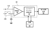
図2Aは、本発明に従う照明デバイス及び照明デバイスの輝度切替デバイスの機能のブロック図である。図2Aを参照すると、本発明の照明デバイスはLED光源110及び輝度切替デバイス100を含む。LED光源は少なくとも1つの発光ダイオード(LED)120から構成され、輝度切替デバイス100は、LED光源110のLED120の各々によって生成された複数の発光状態の輝度を切り替えるために使用される。輝度切替デバイス100は、切替スイッチ130、検出回路60、記憶ユニット70、及び電力変換回路90を有する。更に、LED光源110のLED120は、いくつかの特別なパターンを形成するように、直列、並列、又は直列及び並列に接続できる。
FIG. 2A is a block diagram of functions of a lighting device and a luminance switching device of the lighting device according to the present invention. Referring to FIG. 2A, the lighting device of the present invention includes an
切替スイッチ130は、LED光源110のLED120によって生成された複数の発光状態を切り替えるように、輝度切替デバイス100の検出回路60に電気的に接続される。更に、切替スイッチ130は発光状態に対応する複数の切替モードを有する。
The
検出回路60は、切替スイッチ130の対応する切替モードを検出するために、切替スイッチ130に電気的に接続される。記憶ユニット70は、検出回路60によって検出される切替スイッチ130のある切替モードに対応するLED120の各々によって発せられる光の輝度値を記憶して、LED120の各々の輝度を輝度制御信号に変換するために、検出回路60に電気的に接続される。
The
この実施形態では、電力変換回路90は、交流(AC)/直流(DC)変換器であり、輝度制御信号を検出回路60からLED光源110へ送信するために、検出回路60とLED光源110の間に電気的に接続され、外部電源150によって光源の輝度切替デバイス100に入力されたAC電力を、輝度切替デバイス100及びLED光源110によって受信されて使用されることができるDC電力に変換する。更に、本発明の電力変換回路90はDC/DC変換器であってもよい。この時、外部電源150は、輝度切替デバイス100及びLED光源110に電力を提供するため、DC電源である。
In this embodiment, the
図2Bは、図2Aの検出回路60の簡易回路図である。図2Bを参照すると、本発明の検出回路60は、増幅器62及びアナログ/デジタル変換回路64を含む。増幅器62の前方入力端は電流信号、例えばLED光源110におけるLED120の各々の輝度信号を受信するために使用され、増幅器62の後方入力端は切替スイッチ130に電気的に接続される。アナログ/デジタル変換回路64は、増幅器62及び記憶ユニット70から送信されるアナログ制御信号をデジタル制御信号に変換して、デジタル制御信号を電力変換回路90に送信するために、増幅器62と記憶ユニット70間に電気的に接続される。そして、電力変換回路90はデジタル制御信号を輝度制御信号に変換し、輝度制御信号はLED光源110においてLED120の各々によって発せられた光の輝度を制御するために使用される。
FIG. 2B is a simplified circuit diagram of the
本発明に従う輝度切替デバイス100は、LED光源110においてLED120の各々によって発せられた光の輝度値を正確に調整でき、その動作原則は以下に記述される通りである。図2Aおよび図2Bを再度参照すると、切替スイッチ130がオフされると、輝度切替デバイス100はLED光源110においてLED120の各々によって発せられた光の輝度を検出し、輝度信号112が輝度切替デバイス100の信号入力端102を介して検出回路60の前方入力端に入力される。輝度信号112は電流信号であってもよく、LED光源110のLED120の各々から発せられた光の輝度値を伝達する。検出回路60の増幅器62によって増幅された後、輝度信号112はアナログ/デジタル変換回路64によってデジタル信号に変換され、記憶ユニット70に送信される。この時、記憶ユニット70はLED120の各々によって発せられた光の輝度状態を記憶する。切替スイッチ130がオンされると、LED光源110における複数のLED120は元々設定された状態に従って同一又は異なる輝度状態を取り(LED120の全てがオン状態とすると、LED120によって発せられた光の輝度は同一である)、記憶ユニット70はLED120の各々によって発せられた光の輝度値を記憶する。記憶ユニット70に記憶されたLED120の各々の輝度状態は変換インターフェイス(図示せず)によってアナログ信号に変換され、アナログ信号はアナログ/デジタル変換回路64に送信される。そして、元々設定された状態に達するよう要求される各LED120によって発せられた光の輝度値の制御信号は、その制御信号をLED光源110が受信できる輝度制御信号114に変換するように、電力変換回路90に送信され、各LED120が輝度値を取るようにする。輝度制御信号114は、パルス幅変調(PWM)信号、電圧制御信号、又は電流制御信号であってもよい。
The
切替スイッチ130がオフされてその後オンされると、輝度切替デバイス100は元々設定された状態に従って各LED120によって発せられた光の輝度値を制御する。例えば、この時、少なくとも1つのLED120によって発せられた光の輝度が減少し、LED光源110全体によって示された画像はLED120輝度変化のために異なる視覚効果を示すようにする。本発明の記憶ユニット70は切替スイッチ130がオンされる度に元の設定に従ってLED120が示す異なる輝度値を記憶することができるので、LED光源110におけるLED120の各々が示す輝度値を制御でき、隣接するLED120の影響によって引き起こされる不均一な光の問題は発生しない。
When the
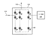
図3は、本発明のLED光源110の他の実施の様態の概略図である。図3を参照すると、この実施形態では、DC電源140はLED光源110に外部的に接続され、LED120の電源として直接的に使用される。この実施形態のその他の部分は上記の実施形態のものと同一であり、ここで再び記述しない。
FIG. 3 is a schematic view of another embodiment of the LED
本発明の切替スイッチ130は共通スイッチであってもよく、手動の切替動作を介して輝度切替デバイス100に外部トリガー信号を提供する。外部トリガー信号は連続する押圧信号であってもよい。ユーザは手で切替スイッチ130を連続的に押圧することができ、ユーザが切替スイッチを押圧して保持する時間の増加と共に、連続切替モードにおけるLED光源110のLED120の輝度は適宜に増加又は減少する。また、外部トリガー信号は多段階押圧信号であってもよい。ユーザは、予め設定した時間の間隔に従って切替スイッチ130を複数の切替モードに設定できる。ユーザが切替スイッチ130を手で連続的に押圧すると、ユーザが切替スイッチを押圧して保持する時間の増加と共に、この連続的切替モードにおけるLED光源110のLED120の輝度は多段階で増加又は多段階で減少する。更に、外部トリガー信号は多段階切替信号であってもよい。ユーザは複数の切替モードに対する切替スイッチ130の切替時間を規定できる。ユーザが手で切替スイッチ130を切り替えると、この切替モードにおけるLED光源110のLED120の輝度は同様に多段階で増加又は多段階で減少する。更に、切替スイッチ130は、LED光源のLED120の多段階切替を実現するように、コンピュータと共に使用されるプログラマブル回路であってもよい。
The
本発明の輝度切替デバイス100は一般のLED表示デバイスだけでなく、LED光源が異なる色(R、G、及びB)の光を発するLEDで構成される限り、多段階照明ランプ、可変色を有する装飾ランプ、可変色を有する照明ランプ等にも適用可能であることは注目すべきである。
The
従来技術と比較すると、本発明に従う照明デバイス及び照明デバイスの輝度切替デバイス100は内蔵型記憶ユニットを含み、切替スイッチ130の予め設定された切替モードの各々においてLEDの各々によって発せられた光の輝度値を記憶する。従って、切替スイッチが切り替えられる度に、LEDは要求された光の輝度値を示すことができ、隣接するLED120によって発せられる光の影響によって引き起こされる不均一な光の問題が防止される。
Compared with the prior art, the lighting device according to the present invention and the
本発明は上述したように、本発明は様々に変更してもよいことは明らかである。そのような変更は本発明の精神及び範囲からの逸脱と見なされるべきでなく、当業者に明確であるような全てのそのような変形は以下の特許請求の範囲内に含まれることが意図されている。 As described above, the present invention may be modified in various ways. Such modifications are not to be regarded as a departure from the spirit and scope of the invention, and all such modifications as would be apparent to one skilled in the art are intended to be included within the scope of the following claims. ing.
Claims (32)
LED光源の発光状態を切り替えるための切替スイッチであり、発光状態に対応する複数の切り替えモードを有する切替スイッチと、
切替スイッチに電気的に接続された、切替スイッチの切替モードを検出するための検出回路と、
検出回路に電気的に接続された記憶ユニットであり、検出回路によって検出された切替スイッチの切替モードに対応するLED光源のLEDの輝度値を記憶し、そのLEDの輝度値を輝度制御信号に変換し、その輝度制御信号を検出回路に送信するための記憶ユニットと、
LED光源に電気的に接続された電力変換回路であり、検出回路から送信された輝度制御信号を受信し、LEDが切替モードに対応する発光状態の輝度を生成するようにするための電力変換回路と、を備える、照明デバイス。 An LED light source composed of at least one light emitting diode (LED), and an LED light source having a plurality of light emitting states;
A changeover switch for switching the light emission state of the LED light source, and a changeover switch having a plurality of changeover modes corresponding to the light emission state;
A detection circuit electrically connected to the changeover switch for detecting the changeover mode of the changeover switch;
A storage unit that is electrically connected to the detection circuit, stores the luminance value of the LED of the LED light source corresponding to the switching mode of the changeover switch detected by the detection circuit, and converts the luminance value of the LED into a luminance control signal A storage unit for transmitting the brightness control signal to the detection circuit;
A power conversion circuit that is electrically connected to the LED light source, receives a luminance control signal transmitted from the detection circuit, and causes the LED to generate luminance in a light emitting state corresponding to the switching mode. And a lighting device.
LED光源の発光状態を受信するための前方入力端を有し、且つ切替スイッチに電気的に接続された、切替スイッチの切替モードを受信するための後方入力端を有する増幅器と、
増幅器及び記憶ユニットに電気的に接続された、増幅器及び記憶ユニットから送信されたアナログ制御信号をデジタル制御信号に変換するためにアナログ/デジタル変換回路と、を備える、
請求項1に記載の照明デバイス。 The detection circuit
An amplifier having a front input end for receiving the light emission state of the LED light source and electrically connected to the changeover switch and having a rear input end for receiving a changeover mode of the changeover switch;
An analog / digital conversion circuit electrically connected to the amplifier and storage unit for converting an analog control signal transmitted from the amplifier and storage unit into a digital control signal;
The lighting device according to claim 1.
輝度切替デバイスに電気的に接続された、LEDの発光状態を切り替えるための切替スイッチであり、複数の発光状態に対応する複数の切替モードを有する切替スイッチと、
切替スイッチに電気的に接続された、切替スイッチの切替モードを検出するための検出回路と、
検出回路に電気的に接続された記憶ユニットであり、検出回路によって検出された切替スイッチの切替モードに対応するLEDの輝度値を記憶し、そのLEDの輝度値を輝度制御信号に変換し、その輝度制御信号を検出回路に送信するための記憶ユニットと、
LED光源に電気的に接続された電力変換回路であり、検出回路から送信された輝度制御信号を受信し、LEDが切替モードに対応する発光状態の輝度を生成するようにするための電力変換回路と、を備える、輝度切替デバイス。 A luminance switching device for switching the luminance of a plurality of light emitting states generated by a light emitting diode (LED) light source including at least one LED, the luminance switching device,
A changeover switch electrically connected to the luminance changeover device for changing the light emission state of the LED, and having a plurality of changeover modes corresponding to a plurality of light emission states;
A detection circuit electrically connected to the changeover switch for detecting the changeover mode of the changeover switch;
A storage unit that is electrically connected to the detection circuit, stores the luminance value of the LED corresponding to the switching mode of the changeover switch detected by the detection circuit, converts the luminance value of the LED into a luminance control signal, and A storage unit for transmitting a brightness control signal to the detection circuit;
A power conversion circuit that is electrically connected to the LED light source, receives a luminance control signal transmitted from the detection circuit, and causes the LED to generate luminance in a light emitting state corresponding to the switching mode. And a luminance switching device.
LED光源の発光状態を受信するための前方入力端、及び切替スイッチに電気的に接続された、切替スイッチの切替モードを受信するための後方入力端を有する増幅器と、
増幅器及び記憶ユニットに電気的に接続された、増幅器及び記憶ユニットから送信されたアナログ制御信号をデジタル制御信号に変換するためのアナログ/デジタル変換回路とからなる、請求項17に記載の輝度切替デバイス。 The detection circuit
An amplifier having a front input end for receiving the light emission state of the LED light source and a rear input end electrically connected to the changeover switch for receiving the changeover mode of the changeover switch;
18. The luminance switching device according to claim 17, further comprising an analog / digital conversion circuit that is electrically connected to the amplifier and the storage unit and converts an analog control signal transmitted from the amplifier and the storage unit into a digital control signal. .
Applications Claiming Priority (1)
| Application Number | Priority Date | Filing Date | Title |
|---|---|---|---|
| TW095141807A TW200821555A (en) | 2006-11-10 | 2006-11-10 | Illuminating apparatus and brightness switching device thereof |
Publications (1)
| Publication Number | Publication Date |
|---|---|
| JP2008123982A true JP2008123982A (en) | 2008-05-29 |
Family
ID=39474924
Family Applications (1)
| Application Number | Title | Priority Date | Filing Date |
|---|---|---|---|
| JP2007015427A Pending JP2008123982A (en) | 2006-11-10 | 2007-01-25 | Illumination device and luminance switching device of illumination device |
Country Status (4)
| Country | Link |
|---|---|
| US (1) | US7777703B2 (en) |
| JP (1) | JP2008123982A (en) |
| KR (1) | KR100824057B1 (en) |
| TW (1) | TW200821555A (en) |
Cited By (2)
| Publication number | Priority date | Publication date | Assignee | Title |
|---|---|---|---|---|
| KR101070795B1 (en) | 2011-05-04 | 2011-10-06 | 주식회사 베스트디지탈 | Autometic lighting control system using dc power source and method thereof |
| TWI394486B (en) * | 2008-11-28 | 2013-04-21 | Princeton Technology Corp | Methods for controlling brightness of an illuminant |
Families Citing this family (28)
| Publication number | Priority date | Publication date | Assignee | Title |
|---|---|---|---|---|
| US8118447B2 (en) | 2007-12-20 | 2012-02-21 | Altair Engineering, Inc. | LED lighting apparatus with swivel connection |
| US8360599B2 (en) | 2008-05-23 | 2013-01-29 | Ilumisys, Inc. | Electric shock resistant L.E.D. based light |
| KR101016422B1 (en) | 2008-07-25 | 2011-02-18 | 엘이디라이텍(주) | indoor lighting apparatus for car |
| US7938562B2 (en) | 2008-10-24 | 2011-05-10 | Altair Engineering, Inc. | Lighting including integral communication apparatus |
| US8214084B2 (en) | 2008-10-24 | 2012-07-03 | Ilumisys, Inc. | Integration of LED lighting with building controls |
| US8324817B2 (en) | 2008-10-24 | 2012-12-04 | Ilumisys, Inc. | Light and light sensor |
| US8653984B2 (en) | 2008-10-24 | 2014-02-18 | Ilumisys, Inc. | Integration of LED lighting control with emergency notification systems |
| US8901823B2 (en) | 2008-10-24 | 2014-12-02 | Ilumisys, Inc. | Light and light sensor |
| US8362710B2 (en) * | 2009-01-21 | 2013-01-29 | Ilumisys, Inc. | Direct AC-to-DC converter for passive component minimization and universal operation of LED arrays |
| US8304999B2 (en) * | 2009-06-08 | 2012-11-06 | Sunpaltech Co., Ltd. | LED controlling driver and controlling method thereof |
| TWI404460B (en) * | 2009-07-21 | 2013-08-01 | An electronic ballast that senses the brightness of the power line | |
| US20110133665A1 (en) * | 2009-12-09 | 2011-06-09 | Mei-Yueh Huang | Luminance adjusting device |
| WO2011119921A2 (en) | 2010-03-26 | 2011-09-29 | Altair Engineering, Inc. | Led light with thermoelectric generator |
| US8540401B2 (en) | 2010-03-26 | 2013-09-24 | Ilumisys, Inc. | LED bulb with internal heat dissipating structures |
| JP2012063436A (en) * | 2010-09-14 | 2012-03-29 | Casio Comput Co Ltd | Projection device, projection method and program |
| WO2012058556A2 (en) | 2010-10-29 | 2012-05-03 | Altair Engineering, Inc. | Mechanisms for reducing risk of shock during installation of light tube |
| TWI416033B (en) * | 2011-01-14 | 2013-11-21 | Nat Univ Chin Yi Technology | Full-color led table lamp |
| US9072171B2 (en) | 2011-08-24 | 2015-06-30 | Ilumisys, Inc. | Circuit board mount for LED light |
| US9184518B2 (en) | 2012-03-02 | 2015-11-10 | Ilumisys, Inc. | Electrical connector header for an LED-based light |
| US9163794B2 (en) | 2012-07-06 | 2015-10-20 | Ilumisys, Inc. | Power supply assembly for LED-based light tube |
| US9271367B2 (en) | 2012-07-09 | 2016-02-23 | Ilumisys, Inc. | System and method for controlling operation of an LED-based light |
| US8884530B2 (en) * | 2013-02-07 | 2014-11-11 | Wen-Sung Lee | Intelligent illuminating device |
| CN103152927B (en) * | 2013-02-19 | 2016-04-13 | 英飞特电子(杭州)股份有限公司 | A kind of LED and light-dimming method thereof |
| US9285084B2 (en) | 2013-03-14 | 2016-03-15 | Ilumisys, Inc. | Diffusers for LED-based lights |
| US9267650B2 (en) | 2013-10-09 | 2016-02-23 | Ilumisys, Inc. | Lens for an LED-based light |
| KR20160111975A (en) | 2014-01-22 | 2016-09-27 | 일루미시스, 인크. | Led-based light with addressed leds |
| US9510400B2 (en) | 2014-05-13 | 2016-11-29 | Ilumisys, Inc. | User input systems for an LED-based light |
| US10161568B2 (en) | 2015-06-01 | 2018-12-25 | Ilumisys, Inc. | LED-based light with canted outer walls |
Citations (6)
| Publication number | Priority date | Publication date | Assignee | Title |
|---|---|---|---|---|
| JPH05217679A (en) * | 1991-03-25 | 1993-08-27 | Matsushita Electric Works Ltd | Illumination control device |
| JPH06508239A (en) * | 1992-03-31 | 1994-09-14 | ラトロン エレクトロニクス カンパニー,インコーポレイティド | lighting control device |
| JP2001307889A (en) * | 2000-04-25 | 2001-11-02 | Matsushita Electric Works Ltd | Automatic photoelectric type on-off switch |
| JP2002100486A (en) * | 2000-09-26 | 2002-04-05 | Olympus Optical Co Ltd | Adjustment method of lighting system, adjustment system of lighting system and lighting system adjusting jig |
| JP2002329586A (en) * | 2001-04-27 | 2002-11-15 | Matsushita Electric Works Ltd | Lighting system and luminaire |
| JP2004253309A (en) * | 2003-02-21 | 2004-09-09 | Nichia Chem Ind Ltd | Special purpose led illumination with color rendering properties |
Family Cites Families (9)
| Publication number | Priority date | Publication date | Assignee | Title |
|---|---|---|---|---|
| JPS6029232A (en) * | 1983-07-07 | 1985-02-14 | Fanuc Ltd | Taper machining method |
| US6861809B2 (en) | 1998-09-18 | 2005-03-01 | Gentex Corporation | Headlamp control to prevent glare |
| US6344641B1 (en) | 1999-08-11 | 2002-02-05 | Agilent Technologies, Inc. | System and method for on-chip calibration of illumination sources for an integrated circuit display |
| US6608614B1 (en) | 2000-06-22 | 2003-08-19 | Rockwell Collins, Inc. | Led-based LCD backlight with extended color space |
| JP4490650B2 (en) * | 2002-04-26 | 2010-06-30 | 東芝モバイルディスプレイ株式会社 | EL display device driving method and EL display device |
| JP2004311635A (en) * | 2003-04-04 | 2004-11-04 | Olympus Corp | Driving device, lighting device using the same, and indicating device using the lighting device |
| FR2854252B1 (en) * | 2003-04-25 | 2005-08-05 | Thales Sa | COLORIMETRIC PHOTO PARAMETERS ASSEMBLY DEVICE FOR COLOR LED LUMINATED BOX |
| CN100426538C (en) * | 2003-07-28 | 2008-10-15 | 日亚化学工业株式会社 | Light-emitting apparatus, led illumination, led light-emitting apparatus, and method of controlling light-emitting apparatus |
| DE102004045515A1 (en) | 2004-09-20 | 2006-03-30 | Patent-Treuhand-Gesellschaft für elektrische Glühlampen mbH | Illumination system with at least two light sources and method for operating such a lighting system |
-
2006
- 2006-11-10 TW TW095141807A patent/TW200821555A/en unknown
-
2007
- 2007-01-11 KR KR1020070003461A patent/KR100824057B1/en active IP Right Grant
- 2007-01-12 US US11/652,693 patent/US7777703B2/en active Active
- 2007-01-25 JP JP2007015427A patent/JP2008123982A/en active Pending
Patent Citations (6)
| Publication number | Priority date | Publication date | Assignee | Title |
|---|---|---|---|---|
| JPH05217679A (en) * | 1991-03-25 | 1993-08-27 | Matsushita Electric Works Ltd | Illumination control device |
| JPH06508239A (en) * | 1992-03-31 | 1994-09-14 | ラトロン エレクトロニクス カンパニー,インコーポレイティド | lighting control device |
| JP2001307889A (en) * | 2000-04-25 | 2001-11-02 | Matsushita Electric Works Ltd | Automatic photoelectric type on-off switch |
| JP2002100486A (en) * | 2000-09-26 | 2002-04-05 | Olympus Optical Co Ltd | Adjustment method of lighting system, adjustment system of lighting system and lighting system adjusting jig |
| JP2002329586A (en) * | 2001-04-27 | 2002-11-15 | Matsushita Electric Works Ltd | Lighting system and luminaire |
| JP2004253309A (en) * | 2003-02-21 | 2004-09-09 | Nichia Chem Ind Ltd | Special purpose led illumination with color rendering properties |
Cited By (2)
| Publication number | Priority date | Publication date | Assignee | Title |
|---|---|---|---|---|
| TWI394486B (en) * | 2008-11-28 | 2013-04-21 | Princeton Technology Corp | Methods for controlling brightness of an illuminant |
| KR101070795B1 (en) | 2011-05-04 | 2011-10-06 | 주식회사 베스트디지탈 | Autometic lighting control system using dc power source and method thereof |
Also Published As
| Publication number | Publication date |
|---|---|
| KR100824057B1 (en) | 2008-04-21 |
| TWI310455B (en) | 2009-06-01 |
| US20080129211A1 (en) | 2008-06-05 |
| TW200821555A (en) | 2008-05-16 |
| US7777703B2 (en) | 2010-08-17 |
Similar Documents
| Publication | Publication Date | Title |
|---|---|---|
| JP2008123982A (en) | Illumination device and luminance switching device of illumination device | |
| EP1926350B1 (en) | Illuminating device and luminance switching thereof | |
| JP5808908B2 (en) | Lighting device with LED for detection | |
| EP1800401B1 (en) | Control apparatus and method with increased resolution for use with modulated light sources | |
| TWI416988B (en) | Improved lighting system | |
| JP2011165394A (en) | Led drive circuit, dimming device, led illumination fixture, led illumination device, and led illumination system | |
| JP2008166674A (en) | Driving circuit for light emitting diode | |
| TWI403215B (en) | Color Modulation System and Its Modulation Method | |
| TW200727047A (en) | Flat lighting source, luminance correcting circuit, luminance correcting method and liquid crystal display | |
| JP5299722B2 (en) | LED lighting device | |
| JP3169679U (en) | Lighting device with adjustable color temperature | |
| JP2008210588A (en) | Illumination device and illumination system | |
| JP2008206087A (en) | Visible optical communication system | |
| JP2011150878A (en) | Led lighting device and illumination device | |
| JP5016323B2 (en) | LED control system | |
| JP2011113793A (en) | Led lighting device and lighting system | |
| TW201515509A (en) | LED driver circuits | |
| KR101987906B1 (en) | Apparatus for supplying power with converting power by number of Light Emitting Diode and method for controlling supplying of power thereof | |
| TW200518005A (en) | Dimming control method and lighting system employing the same | |
| JP2010206085A (en) | Light emitting device, lighting system and method of driving the lighting system | |
| JP2010218794A (en) | Led automatic light dimming lighting system | |
| CN111770604B (en) | Light emitting device and control method thereof | |
| KR101546125B1 (en) | Apparatus and method for controlling output of lighting | |
| JP6399445B2 (en) | Lighting control system | |
| KR20060100658A (en) | Method for operating led on-off |
Legal Events
| Date | Code | Title | Description |
|---|---|---|---|
| A131 | Notification of reasons for refusal |
Free format text: JAPANESE INTERMEDIATE CODE: A131 Effective date: 20091006 |
|
| A02 | Decision of refusal |
Free format text: JAPANESE INTERMEDIATE CODE: A02 Effective date: 20100629 |