JP2008106909A - Magnetic bearing control device and turbo-molecular pump - Google Patents
Magnetic bearing control device and turbo-molecular pump Download PDFInfo
- Publication number
- JP2008106909A JP2008106909A JP2006292646A JP2006292646A JP2008106909A JP 2008106909 A JP2008106909 A JP 2008106909A JP 2006292646 A JP2006292646 A JP 2006292646A JP 2006292646 A JP2006292646 A JP 2006292646A JP 2008106909 A JP2008106909 A JP 2008106909A
- Authority
- JP
- Japan
- Prior art keywords
- bias current
- current
- control
- magnetic bearing
- bias
- Prior art date
- Legal status (The legal status is an assumption and is not a legal conclusion. Google has not performed a legal analysis and makes no representation as to the accuracy of the status listed.)
- Pending
Links
Images


Classifications
-
- F—MECHANICAL ENGINEERING; LIGHTING; HEATING; WEAPONS; BLASTING
- F16—ENGINEERING ELEMENTS AND UNITS; GENERAL MEASURES FOR PRODUCING AND MAINTAINING EFFECTIVE FUNCTIONING OF MACHINES OR INSTALLATIONS; THERMAL INSULATION IN GENERAL
- F16C—SHAFTS; FLEXIBLE SHAFTS; ELEMENTS OR CRANKSHAFT MECHANISMS; ROTARY BODIES OTHER THAN GEARING ELEMENTS; BEARINGS
- F16C32/00—Bearings not otherwise provided for
- F16C32/04—Bearings not otherwise provided for using magnetic or electric supporting means
- F16C32/0406—Magnetic bearings
- F16C32/044—Active magnetic bearings
- F16C32/0444—Details of devices to control the actuation of the electromagnets
-
- F—MECHANICAL ENGINEERING; LIGHTING; HEATING; WEAPONS; BLASTING
- F16—ENGINEERING ELEMENTS AND UNITS; GENERAL MEASURES FOR PRODUCING AND MAINTAINING EFFECTIVE FUNCTIONING OF MACHINES OR INSTALLATIONS; THERMAL INSULATION IN GENERAL
- F16C—SHAFTS; FLEXIBLE SHAFTS; ELEMENTS OR CRANKSHAFT MECHANISMS; ROTARY BODIES OTHER THAN GEARING ELEMENTS; BEARINGS
- F16C2360/00—Engines or pumps
- F16C2360/44—Centrifugal pumps
- F16C2360/45—Turbo-molecular pumps
Abstract
Description
本発明は、磁気軸受の制御装置に関し、特に、ターボ分子ポンプ、真空ポンプ、コンプレッサ、または、複数のターボ分子ポンプを有する半導体製造装置に使用されれば好適な磁気軸受の制御装置に関する。また、本発明は、ターボ分子ポンプに関する。 The present invention relates to a control device for a magnetic bearing, and more particularly to a control device for a magnetic bearing that is suitable for use in a semiconductor manufacturing apparatus having a turbo molecular pump, a vacuum pump, a compressor, or a plurality of turbo molecular pumps. The present invention also relates to a turbo molecular pump.
従来、磁気軸受の制御装置としては、ターボ分子ポンプの回転軸を非接触に支持する磁気軸受を制御しているものがある。 Conventionally, as a control apparatus for a magnetic bearing, there is one that controls a magnetic bearing that supports a rotating shaft of a turbo molecular pump in a non-contact manner.
従来の磁気軸受の制御装置は、回転軸の振れ(変位)の大きさに無関係に常時一定の値をとるバイアス電流に、回転軸の振れ(変位)の値の大きさに基づいて適切に変動させた指令電流を加えて制御電流を生成して、この制御電流に基づいて磁気軸受の制御を行っている。 The conventional magnetic bearing control device appropriately changes the bias current that always takes a constant value regardless of the magnitude (displacement) of the rotating shaft based on the magnitude of the value of the rotating shaft (displacement). A control current is generated by adding the commanded current, and the magnetic bearing is controlled based on the control current.
このような背景において、ターボ分子ポンプに設置されている磁気軸受の制御装置の運転コストを小さくすることが所望されている。また、回転軸の振れが大きい状態であっても、磁気軸受に回転軸を安定に支持させることができる磁気軸受の制御装置が所望されている。
そこで、本発明の課題は、運転コストが小さくて、かつ、回転軸の振れが大きい状態であっても、磁気軸受に回転軸を安定に支持させることができる磁気軸受の制御装置を提供することにある。また、本発明の課題は、運転コストが小さくて、かつ、回転軸の振れが大きい状態であっても、磁気軸受に回転軸を安定に支持させることができるターボ分子ポンプを提供することにある。 Accordingly, an object of the present invention is to provide a magnetic bearing control device that can stably support a rotating shaft on a magnetic bearing even when the operating cost is low and the rotating shaft has a large runout. It is in. Another object of the present invention is to provide a turbo molecular pump capable of stably supporting a rotating shaft on a magnetic bearing even when the operating cost is low and the swing of the rotating shaft is large. .
上記課題を解決するため、この発明の磁気軸受の制御装置は、
少なくとも第1バイアス電流および第2バイアス電流を生成するバイアス電流生成部と、
上記第1バイアス電流または上記第2バイアス電流と、指令電流とに基づいて制御電流を生成する制御電流生成部と、
上記制御電流生成部からの上記制御電流と、所定の閾値との比較結果に基づいて、上記第1バイアス電流または上記第2バイアス電流を選択して、上記制御電流生成部に出力するバイアス電流選択部と
を備えることを特徴としている。
In order to solve the above problems, a control device for a magnetic bearing of the present invention provides
A bias current generator for generating at least a first bias current and a second bias current;
A control current generator for generating a control current based on the first bias current or the second bias current and the command current;
Bias current selection for selecting the first bias current or the second bias current based on a comparison result between the control current from the control current generation unit and a predetermined threshold and outputting the selected current to the control current generation unit It is characterized by providing a part.
上記「上記制御電流生成部からの上記制御電流」という文言における「上記制御電流」には、磁気軸受の制御に用いる制御電流が含まれるのは勿論のこと、磁気軸受の制御に用いる制御電流に何らかの演算が施された制御電流の情報を含んだ値が含まれるものとする。このことから、例えば、上記「上記制御電流生成部からの上記制御電流」という文言における「上記制御電流」には、磁気軸受の制御に用いる制御電流を2倍した値等が含まれる。 The term “the control current” in the term “the control current from the control current generator” includes the control current used for controlling the magnetic bearing as well as the control current used for controlling the magnetic bearing. It is assumed that a value including information on the control current that has been subjected to some calculation is included. Therefore, for example, the “control current” in the term “the control current from the control current generator” includes a value obtained by doubling the control current used for controlling the magnetic bearing.
また、上記「上記制御電流生成部に出力する」という文言には、上記バイアス電流選択部からの信号を受けた上記バイアス電流生成部が、上記制御電流生成部に上記第1バイアス電流または上記第2バイアス電流を出力する場合と、
上記バイアス電流生成部からの信号と、上記制御電流生成部からの信号とを受けた上記バイアス電流選択部が、上記制御電流生成部に上記第1バイアス電流または上記第2バイアス電流を出力する場合
の両方が含まれるものとする。
In addition, the phrase “output to the control current generation unit” includes that the bias current generation unit that receives a signal from the bias current selection unit sends the first bias current or the first bias to the control current generation unit. 2 bias current output,
When the bias current selection unit receiving the signal from the bias current generation unit and the signal from the control current generation unit outputs the first bias current or the second bias current to the control current generation unit Both are included.
本発明によれば、バイアス電流選択部が、制御電流生成部からの制御電流と、所定の閾値との比較結果に基づいて、第1バイアス電流または第2バイアス電流を選択して、上記制御電流生成部に出力するから、バイアス電流を、適宜適切な値に切り換えることができる。すなわち、バイアス電流が、回転軸の振れ(変位)の大きさに無関係に常時一定の値に設定されることがなく、バイアス電流を、例えば、回転軸の振れが小さくて、回転軸が安定に回転している状態において、小さく設定することができるから、回転軸が安定に回転している状態おいて、消費電流を低減することができる。 According to the present invention, the bias current selection unit selects the first bias current or the second bias current based on the comparison result between the control current from the control current generation unit and the predetermined threshold, and the control current Since it outputs to a production | generation part, a bias current can be switched to an appropriate value suitably. That is, the bias current is not always set to a constant value regardless of the magnitude (displacement) of the rotation axis, and the bias current can be set to be stable, for example, with a small rotation axis. Since it can be set small in the rotating state, the current consumption can be reduced in the state where the rotating shaft is rotating stably.
また、本発明によれば、例えば、回転軸の振れが大きい状態において、バイアス電流を大きく設定することができるから、回転軸の振れが大きい場合であっても、磁気軸受で回転軸を安定に支持することができる。 In addition, according to the present invention, for example, the bias current can be set large in a state where the rotation shaft has a large runout. Can be supported.
また、一実施形態の磁気軸受の制御装置は、
磁気軸受が支持する回転軸の位置を検出するセンサからの出力に基づいて、上記指令電流を生成して、上記制御電流生成部に出力する指令電流生成部を備え、
上記第2バイアス電流は、上記第1バイアス電流よりも大きく、
上記バイアス電流選択部は、上記制御電流の値が上記閾値より小さい値であるとき、上記第1バイアス電流を選択する一方、上記制御電流の値が上記閾値以上の値になったとき、上記第2バイアス電流を選択する。
In addition, the magnetic bearing control device of one embodiment
Based on the output from the sensor that detects the position of the rotary shaft supported by the magnetic bearing, the command current is generated and output to the control current generating unit.
The second bias current is larger than the first bias current,
The bias current selection unit selects the first bias current when the value of the control current is smaller than the threshold value. On the other hand, the bias current selection unit selects the first bias current when the value of the control current becomes equal to or greater than the threshold value. 2 Bias current is selected.
この明細書では、回転軸の位置を検出するセンサを、回転軸の位置、回転軸の振れ、または、回転軸の変位等、回転軸の位置を特定できる物理量を検出するセンサとして定義する。 In this specification, a sensor that detects the position of the rotating shaft is defined as a sensor that detects a physical quantity that can specify the position of the rotating shaft, such as the position of the rotating shaft, the shake of the rotating shaft, or the displacement of the rotating shaft.
上記実施形態によれば、上記バイアス電流選択部が、上記制御電流生成部からの制御電流と、上記閾値とを比較して、上記制御電流の値が上記閾値以上の値になったとき、第1バイアス電流よりも大きい第2バイアス電流を選択するから、回転軸の振れが大きい状態において、バイアス電流を容易に大きく設定することができて、回転軸を安定に支持することができる。 According to the embodiment, the bias current selection unit compares the control current from the control current generation unit with the threshold value, and when the value of the control current becomes equal to or greater than the threshold value, Since the second bias current larger than 1 bias current is selected, the bias current can be easily set large in a state where the swing of the rotating shaft is large, and the rotating shaft can be stably supported.
また、一実施形態の磁気軸受の制御装置は、
磁気軸受が支持する回転軸の位置を検出するセンサからの出力に基づいて、上記指令電流を生成して、上記制御電流生成部に出力する指令電流生成部を備え、
上記第2バイアス電流は、上記第1バイアス電流よりも小さく、
上記バイアス電流選択部は、上記制御電流の値が所定時間の間持続して上記閾値を下まわらないとき、上記第1バイアス電流を選択する一方、上記制御電流の値が所定時間の間持続して上記閾値を下まわったとき、上記第2バイアス電流を選択する。
In addition, the magnetic bearing control device of one embodiment
Based on the output from the sensor that detects the position of the rotary shaft supported by the magnetic bearing, the command current is generated and output to the control current generating unit.
The second bias current is smaller than the first bias current,
The bias current selection unit selects the first bias current when the value of the control current continues for a predetermined time and does not fall below the threshold value, while the value of the control current continues for a predetermined time. When the value falls below the threshold, the second bias current is selected.
上記実施形態によれば、上記バイアス電流選択部が、制御電流生成部からの制御電流と、上記閾値とを比較して、上記制御電流の値が所定時間の間持続して上記閾値を下まわったとき、第1バイアス電流よりも小さい第2バイアス電流を選択するから、回転軸が安定に回転している状態において、バイアス電流を容易に小さく設定することができて、磁気軸受制御装置の運転コストを低減できる。 According to the embodiment, the bias current selection unit compares the control current from the control current generation unit with the threshold value, and the value of the control current continues for a predetermined time and falls below the threshold value. Since the second bias current smaller than the first bias current is selected, the bias current can be easily set small in a state where the rotation shaft is stably rotated, and the magnetic bearing control device is operated. Cost can be reduced.
また、一実施形態の磁気軸受の制御装置は、
上記制御電流生成部は、磁気軸受が支持する回転軸の位置を検出するセンサからの出力に基づいて、上記制御電流を生成し、
上記第2バイアス電流は、上記第1バイアス電流よりも大きく、
上記バイアス電流選択部は、上記制御電流の値が上記閾値より小さい値であるとき、上記第1バイアス電流を選択する一方、上記制御電流の値が上記閾値以上の値になったとき、上記第2バイアス電流を選択する。
In addition, the magnetic bearing control device of one embodiment
The control current generation unit generates the control current based on an output from a sensor that detects the position of the rotating shaft supported by the magnetic bearing,
The second bias current is larger than the first bias current,
The bias current selection unit selects the first bias current when the value of the control current is smaller than the threshold value. On the other hand, the bias current selection unit selects the first bias current when the value of the control current becomes equal to or greater than the threshold value. 2 Bias current is selected.
上記実施形態によれば、上記バイアス電流選択部が、上記制御電流生成部からの制御電流と、上記閾値とを比較して、上記制御電流の値が上記閾値以上の値になったとき、第1バイアス電流よりも大きい第2バイアス電流を選択するから、回転軸の振れが大きい状態において、バイアス電流を容易に大きく設定することができて、回転軸を安定に支持することができる。 According to the embodiment, the bias current selection unit compares the control current from the control current generation unit with the threshold value, and when the value of the control current becomes equal to or greater than the threshold value, Since the second bias current larger than 1 bias current is selected, the bias current can be easily set large in a state where the swing of the rotating shaft is large, and the rotating shaft can be stably supported.
また、一実施形態の磁気軸受の制御装置は、
上記制御電流生成部は、磁気軸受が支持する回転軸の位置を検出するセンサからの出力に基づいて、上記制御電流を生成し、
上記第2バイアス電流は、上記第1バイアス電流よりも小さく、
上記バイアス電流選択部は、上記制御電流の値が所定時間の間持続して上記閾値を下まわらないとき、上記第1バイアス電流を選択する一方、上記制御電流の値が所定時間の間持続して上記閾値を下まわったとき、上記第2バイアス電流を選択する。
In addition, the magnetic bearing control device of one embodiment
The control current generation unit generates the control current based on an output from a sensor that detects the position of the rotating shaft supported by the magnetic bearing,
The second bias current is smaller than the first bias current,
The bias current selection unit selects the first bias current when the value of the control current continues for a predetermined time and does not fall below the threshold value, while the value of the control current continues for a predetermined time. When the value falls below the threshold, the second bias current is selected.
上記実施形態によれば、上記バイアス電流選択部が、制御電流生成部からの制御電流と、上記閾値とを比較して、上記制御電流の値が所定時間の間持続して上記閾値を下まわったとき、第1バイアス電流よりも小さい第2バイアス電流を選択するから、回転軸が安定に回転している状態において、バイアス電流を容易に小さく設定することができて、磁気軸受制御装置の運転コストを低減できる。 According to the embodiment, the bias current selection unit compares the control current from the control current generation unit with the threshold value, and the value of the control current continues for a predetermined time and falls below the threshold value. Since the second bias current smaller than the first bias current is selected, the bias current can be easily set small in a state where the rotation shaft is stably rotated, and the magnetic bearing control device is operated. Cost can be reduced.
また、一実施形態の磁気軸受の制御装置は、
上記バイアス電流選択部は、上記制御電流の大きさに対応するバイアス電流を予め規定しているバイアス電流テーブルに基づいて上記第1バイアス電流または上記第2バイアス電流を選択する。
In addition, the magnetic bearing control device of one embodiment
The bias current selection unit selects the first bias current or the second bias current based on a bias current table that predefines a bias current corresponding to the magnitude of the control current.
上記実施形態によれば、上記バイアス電流選択部が、上記制御電流の大きさに対応するバイアス電流を予め規定しているバイアス電流テーブルに基づいて上記バイアス電流を選択するから、磁気軸受の制御装置が設置される装置の仕様、すなわち、装置の大きさや装置の構成等によって、バイアス電流を容易に変更設定することができて、適切なバイアス電流を容易に生成することができる。 According to the embodiment, the bias current selection unit selects the bias current based on a bias current table that predefines a bias current corresponding to the magnitude of the control current. The bias current can be easily changed and set according to the specifications of the device in which the device is installed, that is, the size of the device and the configuration of the device, and an appropriate bias current can be easily generated.
また、本発明のターボ分子ポンプは、
回転軸と、
上記回転軸を駆動するモータと、
上記回転軸を、ラジアル方向およびアキシアル方向のうちの少なくとも一方の方向に磁気的に非接触に支持する磁気軸受と、
上記磁気軸受を制御する磁気軸受の制御装置と
を備え、
上記磁気軸受の制御装置は、
少なくとも第1バイアス電流および第2バイアス電流を生成するバイアス電流生成部と、
上記第1バイアス電流または上記第2バイアス電流と、指令電流とに基づいて制御電流を生成する制御電流生成部と、
上記制御電流生成部からの上記制御電流と、所定の閾値との比較結果に基づいて、上記第1バイアス電流または上記第2バイアス電流を選択して、上記制御電流生成部に出力するバイアス電流選択部と
を有し、
上記磁気軸受を、上記制御電流に基づいて制御することを特徴としている。
The turbo molecular pump of the present invention is
A rotation axis;
A motor for driving the rotating shaft;
A magnetic bearing that supports the rotating shaft in a non-contact manner in at least one of a radial direction and an axial direction;
A magnetic bearing control device for controlling the magnetic bearing,
The magnetic bearing control device is:
A bias current generator for generating at least a first bias current and a second bias current;
A control current generator for generating a control current based on the first bias current or the second bias current and the command current;
Bias current selection for selecting the first bias current or the second bias current based on a comparison result between the control current from the control current generation unit and a predetermined threshold and outputting the selected current to the control current generation unit And
The magnetic bearing is controlled based on the control current.
ターボ分子ポンプは、運転中の殆どの時間において、回転軸が定格回転速度付近で回転するようになっている。したがって、回転軸が、定格回転速度付近で回転しているときの運転コストを低減することができれば、ターボ分子ポンプの運転コストを格段に低減することができることになる。 The turbo molecular pump is configured such that the rotating shaft rotates around the rated rotational speed for most of the time during operation. Therefore, if the operating cost when the rotating shaft rotates around the rated rotational speed can be reduced, the operating cost of the turbo molecular pump can be significantly reduced.
本発明によれば、磁気軸受の制御装置は、バイアス電流を、適宜変更させることができるから、回転軸が定格回転速度付近で回転していて回転軸が安定に回転している状態において、バイアス電流を小さく設定することができ、かつ、回転軸の振れが大きい状態において、バイアス電流を大きく設定することができる。したがって、ターボ分子ポンプの運転コストを格段に低減できると共に、回転軸の振れが大きい場合において、回転軸を安定に制御することができる。 According to the present invention, the magnetic bearing control device can change the bias current as appropriate, so that the rotating shaft rotates in the vicinity of the rated rotational speed and the rotating shaft is stably rotated. The bias current can be set large in a state where the current can be set small and the swing of the rotating shaft is large. Therefore, the operating cost of the turbo molecular pump can be remarkably reduced, and the rotating shaft can be stably controlled when the swinging of the rotating shaft is large.
また、この発明に含まれる磁気軸受の制御装置と、この発明に含まれるターボ分子ポンプとを、次のように表現することができる。 The magnetic bearing control device included in the present invention and the turbo molecular pump included in the present invention can be expressed as follows.
すなわち、一実施形態の磁気軸受の制御装置は、
回転軸を非接触に支持する磁気軸受を、バイアス電流に指令電流を加えてなる制御電流を用いて制御する磁気軸受の制御装置において、
複数の一定のバイアス電流を生成するバイアス電流生成部と、
上記バイアス電流生成部が一定の第1バイアス電流を生成している第1状態の上記制御電流に基づいて、上記バイアス電流が上記第1バイアス電流と異なる一定の第2バイアス電流である上記第1状態の次の第2状態における上記第2バイアス電流を選択し、上記第2バイアス電流を表す信号を上記バイアス電流生成部に出力するバイアス電流選択部と
を備える。
That is, the control device of the magnetic bearing of one embodiment
In a magnetic bearing control device that controls a magnetic bearing that supports a rotating shaft in a non-contact manner using a control current obtained by adding a command current to a bias current,
A bias current generator for generating a plurality of constant bias currents;
The first bias current is a constant second bias current that is different from the first bias current based on the control current in a first state in which the bias current generator is generating a constant first bias current. A bias current selection unit that selects the second bias current in the second state next to the state and outputs a signal representing the second bias current to the bias current generation unit.
上記実施形態によれば、バイアス電流選択部によって、上記バイアス電流生成部が一定の第1バイアス電流を生成している第1状態の制御電流に基づいて、上記バイアス電流が上記第1バイアス電流と異なる一定の第2バイアス電流である上記第1状態の次の第2状態における上記第2バイアス電流を選択することができて、バイアス電流を、適宜適切な値に切り換えることができる。すなわち、バイアス電流が、回転軸の振れ(変位)の大きさに無関係に常時一定の値に設定されることがなく、バイアス電流を、例えば、回転軸の振れが小さくて、回転軸が安定に回転している状態において、小さく設定することができるから、回転軸が安定に回転している状態おいて、消費電流を低減することができる。 According to the above-described embodiment, the bias current is generated by the bias current selection unit based on the control current in the first state in which the bias current generation unit generates a constant first bias current. The second bias current in the second state next to the first state, which is a different constant second bias current, can be selected, and the bias current can be appropriately switched to an appropriate value. That is, the bias current is not always set to a constant value regardless of the magnitude (displacement) of the rotation axis, and the bias current can be set to be stable, for example, with a small rotation axis. Since it can be set small in the rotating state, the current consumption can be reduced in the state where the rotating shaft is rotating stably.
また、上記実施形態によれば、例えば、回転軸の振れが大きい状態において、バイアス電流を大きく設定することができるから、回転軸の振れが大きい場合であっても、磁気軸受で回転軸を安定に支持することができる。 Further, according to the above-described embodiment, for example, the bias current can be set large in a state where the rotation shaft has a large runout. Therefore, even if the rotation shaft has a large runout, the rotation shaft is stabilized by the magnetic bearing. Can be supported.
また、一実施形態の磁気軸受の制御装置は、
上記回転軸の位置を検出するセンサからの出力に基づいて、上記指令電流を生成する指令電流生成部と、
上記バイアス電流生成部からの出力および上記指令電流生成部からの出力に基づいて上記制御電流を生成する制御電流生成部と
を備え、
上記バイアス電流選択部は、上記制御電流生成部から入力された上記第1状態の制御電流の値と、第1閾値とを比較して、上記第1状態の制御電流の値が上記第1閾値以上の値になったとき、上記第2バイアス電流として、上記第1状態の上記第1バイアス電流よりも一段階値が大きい一定のバイアス電流を選択する一方、上記制御電流生成部からの上記第1状態の制御電流の値と、上記第1閾値よりも低い第2閾値とを比較して、上記第1状態の制御電流の値が所定時間持続して上記第2閾値よりも小さい状態になったとき、上記第2バイアス電流として、上記第1状態の上記第1バイアス電流よりも一段階値が小さい一定のバイアス電流を選択する。
In addition, the magnetic bearing control device of one embodiment
Based on an output from a sensor that detects the position of the rotating shaft, a command current generator that generates the command current;
A control current generator that generates the control current based on an output from the bias current generator and an output from the command current generator;
The bias current selection unit compares the value of the control current in the first state input from the control current generation unit with a first threshold value, and the value of the control current in the first state is the first threshold value. When the above value is reached, a constant bias current having a one-step value larger than the first bias current in the first state is selected as the second bias current, while the first bias current from the control current generator is selected. The value of the control current in the first state is compared with the second threshold value lower than the first threshold value, and the value of the control current in the first state lasts for a predetermined time and becomes smaller than the second threshold value. In this case, a constant bias current having a one-step value smaller than the first bias current in the first state is selected as the second bias current.
上記実施形態によれば、上記バイアス電流選択部が、上記制御電流生成部から入力された上記第1状態の制御電流の値と、閾値とを比較することにより、第2状態の第2バイアス電流を選択するようになっているから、回転軸が安定に回転している状態において、バイアス電流を容易に小さく設定することができ、かつ、回転軸の振れが大きい状態において、バイアス電流を容易に大きく設定することができる。 According to the above embodiment, the bias current selection unit compares the value of the control current in the first state input from the control current generation unit with a threshold value, thereby obtaining the second bias current in the second state. Therefore, the bias current can be easily set small when the rotating shaft is stably rotating, and the bias current can be easily set when the swing of the rotating shaft is large. Can be set large.
また、一実施形態の磁気軸受の制御装置は、
上記回転軸の位置を検出するセンサからの出力に基づいて、上記制御電流を生成する制御電流生成部を備え、
上記バイアス電流選択部は、上記制御電流生成部から入力された上記第1状態の制御電流の値と、第1閾値とを比較して、上記第1状態の制御電流の値が上記第1閾値以上の値になったとき、上記第2バイアス電流として、上記第1状態の上記第1バイアス電流よりも一段階値が大きい一定のバイアス電流を選択する一方、上記制御電流生成部からの上記第1状態の制御電流の値と、上記第1閾値よりも低い第2閾値とを比較して、上記第1状態の制御電流の値が所定時間持続して上記第2閾値よりも小さい状態になったとき、上記第2バイアス電流として、上記第1状態の第1バイアス電流よりも一段階値が小さい一定のバイアス電流を選択する。
In addition, the magnetic bearing control device of one embodiment
A control current generator for generating the control current based on an output from a sensor for detecting the position of the rotating shaft;
The bias current selection unit compares the value of the control current in the first state input from the control current generation unit with a first threshold value, and the value of the control current in the first state is the first threshold value. When the above value is reached, a constant bias current having a one-step value larger than the first bias current in the first state is selected as the second bias current, while the first bias current from the control current generator is selected. The value of the control current in the first state is compared with the second threshold value lower than the first threshold value, and the value of the control current in the first state lasts for a predetermined time and becomes smaller than the second threshold value. In this case, a constant bias current having a one-step value smaller than the first bias current in the first state is selected as the second bias current.
上記実施形態によれば、上記バイアス電流選択部が、上記制御電流生成部から入力された上記第1状態の制御電流の値と、閾値とを比較することにより、第2状態の第2バイアス電流を選択するようになっているから、回転軸が安定に回転している状態において、バイアス電流を容易に小さく設定することができ、かつ、回転軸の振れが大きい状態において、バイアス電流を容易に大きく設定することができる。 According to the above embodiment, the bias current selection unit compares the value of the control current in the first state input from the control current generation unit with a threshold value, thereby obtaining the second bias current in the second state. Therefore, the bias current can be easily set small when the rotating shaft is stably rotating, and the bias current can be easily set when the swing of the rotating shaft is large. Can be set large.
また、一実施形態の磁気軸受の制御装置は、上記バイアス電流選択部が、上記制御電流の大きさに対応するバイアス電流を予め規定しているバイアス電流テーブルに基づいて上記バイアス電流を選択する。 In one embodiment of the magnetic bearing control device, the bias current selection unit selects the bias current based on a bias current table that predefines a bias current corresponding to the magnitude of the control current.
上記実施形態によれば、上記バイアス電流選択部が、上記制御電流の大きさに対応するバイアス電流を予め規定しているバイアス電流テーブルに基づいて上記バイアス電流を選択するから、磁気軸受の制御装置が設置される装置の仕様、すなわち、装置の大きさや装置の構成等によって、バイアス電流を容易に変更設定することができて、適切なバイアス電流を容易に生成することができる。 According to the embodiment, the bias current selection unit selects the bias current based on a bias current table that predefines a bias current corresponding to the magnitude of the control current. The bias current can be easily changed and set according to the specifications of the device in which the device is installed, that is, the size of the device and the configuration of the device, and an appropriate bias current can be easily generated.
また、一実施形態のターボ分子ポンプは、
回転軸と、
上記回転軸を駆動するモータと、
上記回転軸を、ラジアル方向およびアキシアル方向のうちの少なくとも一方の方向に磁気的に非接触に支持する磁気軸受と、
上記磁気軸受を、バイアス電流に指令電流を加えてなる制御電流を用いて制御する磁気軸受の制御装置と
を備え、
上記磁気軸受の制御装置は、
複数の一定のバイアス電流を生成するバイアス電流生成部と、
上記バイアス電流生成部が一定の第1バイアス電流を生成している第1状態の上記制御電流に基づいて、上記バイアス電流が上記第1バイアス電流と異なる一定の第2バイアス電流である上記第1状態の次の第2状態における上記第2バイアス電流を選択するバイアス電流選択部と
を有している。
Moreover, the turbo molecular pump of one embodiment is
A rotation axis;
A motor for driving the rotating shaft;
A magnetic bearing that supports the rotating shaft in a non-contact manner in at least one of a radial direction and an axial direction;
A magnetic bearing control device for controlling the magnetic bearing using a control current obtained by adding a command current to a bias current;
The magnetic bearing control device is:
A bias current generator for generating a plurality of constant bias currents;
The first bias current is a constant second bias current that is different from the first bias current based on the control current in a first state in which the bias current generator is generating a constant first bias current. And a bias current selection unit that selects the second bias current in the second state next to the state.
上記実施形態によれば、磁気軸受の制御装置は、バイアス電流を、適宜変更させることができるから、回転軸が定格回転速度付近で回転していて回転軸が安定に回転している状態において、バイアス電流を小さく設定することができ、かつ、回転軸の振れが大きい状態において、バイアス電流を大きく設定することができる。したがって、ターボ分子ポンプの運転コストを格段に低減できると共に、回転軸の振れが大きい場合において、回転軸を安定に制御することができる。 According to the above embodiment, the magnetic bearing control device can change the bias current as appropriate, so that the rotating shaft rotates in the vicinity of the rated rotation speed and the rotating shaft rotates stably. The bias current can be set small, and the bias current can be set large in a state where the swing of the rotating shaft is large. Therefore, the operating cost of the turbo molecular pump can be remarkably reduced, and the rotating shaft can be stably controlled when the swinging of the rotating shaft is large.
本発明の磁気軸受の制御装置によれば、バイアス電流選択部によって、バイアス電流を、適宜適切な値に切り換えることができる。すなわち、バイアス電流が、回転軸の振れ(変位)の大きさに無関係に常時一定の値に設定されることがなく、バイアス電流を、例えば、回転軸の振れが小さくて、回転軸が安定に回転している状態において、小さく設定することができるから、回転軸が安定に回転している状態おいて、消費電流を低減することができる。また、例えば、回転軸の振れが大きい状態において、バイアス電流を大きく設定することができるから、回転軸の振れが大きい場合であっても、磁気軸受で回転軸を安定に支持することができる。 According to the magnetic bearing control apparatus of the present invention, the bias current can be appropriately switched to an appropriate value by the bias current selector. That is, the bias current is not always set to a constant value regardless of the magnitude (displacement) of the rotation axis, and the bias current can be set to be stable, for example, with a small rotation axis. Since it can be set small in the rotating state, the current consumption can be reduced in the state where the rotating shaft is rotating stably. In addition, for example, since the bias current can be set large in a state where the rotation shaft has a large deflection, the rotation shaft can be stably supported by the magnetic bearing even when the rotation shaft has a large deflection.
また、本発明のターボ分子ポンプによれば、磁気軸受の制御装置が、バイアス電流を、適宜変更させることができるから、回転軸が安定に回転している状態において、バイアス電流を小さく設定することができ、かつ、回転軸の振れが大きい状態において、バイアス電流を大きく設定することができる。したがって、運転コストを低減できると共に、回転軸の振れが大きい場合において、磁気軸受で回転軸を安定に制御することができる。 Further, according to the turbo molecular pump of the present invention, the magnetic bearing control device can appropriately change the bias current, so that the bias current can be set small in a state where the rotating shaft is stably rotated. In addition, the bias current can be set large in a state where the swing of the rotating shaft is large. Therefore, the operating cost can be reduced and the rotating shaft can be stably controlled by the magnetic bearing when the rotating shaft has a large runout.
以下、本発明を図示の形態により詳細に説明する。 Hereinafter, the present invention will be described in detail with reference to the drawings.
図1は、本発明の第1実施形態のターボ分子ポンプの模式構成図である。 FIG. 1 is a schematic configuration diagram of a turbo molecular pump according to a first embodiment of the present invention.
このターボ分子ポンプは、ターボ分子ポンプ本体1と、コントローラ2とを備える。
This turbo molecular pump includes a turbo molecular pump main body 1 and a
上記ターボ分子ポンプ本体1は、回転軸4と、回転軸4を駆動するモータ13のステータ7と、回転軸4を磁気的に非接触支持する磁気軸受6と、磁気軸受6が制御不能になったときに回転軸4を機械的に支持する転がり軸受であるタッチダウン軸受20と、回転軸4の回転速度を検出する回転速度センサ8と、回転軸4のラジアル位置およびアキシアル位置を検出する位置検出センサ5とを有する。上記回転軸4は、モータ13のロータとしての役割も兼用している。
In the turbo molecular pump main body 1, the rotating shaft 4, the stator 7 of the
上記モータ13は、電源異常や停電等により電源側からの電力の供給が停止されて電源電圧が低下すると、発電機として電力を出力するようになっている。すなわち、電源側からモータ13に電力が供給されなくなっても、回転軸4は、慣性力でしばらくの間回転し続ける。モータ13は、この慣性力による回転軸4の回転を利用して、電力を供給するようになっている。
The
上記位置検出センサ5、磁気軸受駆動回路10およびモータドライバ11は、電源電圧が低下すると、電源に代わって発電機としてのモータ13から回生電力を供給されるようになっている。そして、上記モータ13から供給される回生電力が磁気軸受6を駆動できる間、この回生電力によって磁気軸受6の磁気浮上制御を行うようになっている。
The
上記位置検出センサ5は、図示は省略したが、アキシアル変位検出部とラジアル変位検出部とを有している。アキシアル変位検出部は、回転軸4のアキシアル方向の変位を検出する1つのアキシアル変位センサを備えている。また、ラジアル変位検出部は、回転軸4のラジアル方向の変位を検出するラジアル変位センサを、2つ備えている。
Although not shown, the
上記磁気軸受6は、図示は省略したが、回転軸4を磁気的に非接触支持する1個のアキシアル磁気軸受と、回転軸4を磁気的に非接触支持する2個のラジアル磁気軸受とを有する。上記アキシアル磁気軸受は、回転軸4のアキシアル方向の両端面を、アキシアル方向の両側から挟むように配置された1対の電磁石(数は2個)を備えている。また、上記各ラジアル磁気軸受は、回転軸4をラジアル方向の両側から挟むように配置された互いに直交する2対の電磁石(各ラジアル磁気軸受において、電磁石の数は4個)を備えている。一方のラジアル磁気軸受は、他方のラジアル磁気軸受に対して回転軸4の軸方向に所定距離離間されて配置されている。 Although not shown in the drawing, the magnetic bearing 6 includes one axial magnetic bearing that supports the rotating shaft 4 in a non-contact manner and two radial magnetic bearings that support the rotating shaft 4 in a non-contact manner. Have. The axial magnetic bearing includes a pair of electromagnets (two in number) arranged so as to sandwich both end surfaces of the rotating shaft 4 in the axial direction from both sides in the axial direction. Each of the radial magnetic bearings includes two pairs of electromagnets orthogonal to each other so as to sandwich the rotating shaft 4 from both sides in the radial direction (in each radial magnetic bearing, the number of electromagnets is four). One radial magnetic bearing is disposed at a predetermined distance from the other radial magnetic bearing in the axial direction of the rotary shaft 4.
上記回転速度センサ8は、回転軸4の回転速度を検出するためのものであり、例えば、回転軸4の1回転当り一定数(例えば1つ)のパルス信号を出力するようになっている。
The
電源異常時や停電時等に、ロータとしての役割を果たす回転軸4の回転速度が下がり、モータ13からの回生電力が磁気軸受6の駆動に必要な電力よりも低下すると、磁気軸受6の磁気浮上制御が停止するようになっている。上記磁気軸受6の磁気浮上制御が停止すると、タッチダウン軸受20が、磁気軸受6の替わりに回転軸4を機械的に支持するようになっている。上記タッチダウン軸受20は、磁気軸受6が制御不能になったときに、回転軸4を支持することによって、磁気軸受6と回転軸4との接触や、回転軸4とステータ7との接触等を防止している。
When the rotational speed of the rotary shaft 4 that functions as a rotor decreases when the power supply is abnormal or when a power failure occurs, the regenerative power from the
上記コントローラ2は、変位演算回路9と、A/D変換器17と、DSP制御装置14と、停電検出回路26と、D/A回路18と、磁気軸受駆動回路10と、モータドライバ11と、発熱制動用回路27とを備える。
The
上記位置検出センサ5、変位演算回路9およびA/D変換器17は、センサ部を構成し、D/A変換器18および磁気軸受駆動回路10は、磁気軸受駆動部を構成し、センサ部、DSP制御装置14、磁気軸受駆動部は、本発明の第1実施形態の磁気軸受の制御装置を構成している。尚、上記DSP制御装置14、A/D変換器17およびD/A変換器18は、DSPボード12を構成している。
The
上記変位演算回路9は、上記アキシアル変位センサの出力に基づいて回転軸4のアキシアル方向の変位を演算するとともに、2つのラジアル変位センサの出力に基づいて回転軸4のラジアル方向の変位を演算し、これらの変位演算値に対応する変位信号をA/D変換器17を介してDSP制御装置14に出力するようになっている。センサ部は、回転軸4のラジアル位置およびアキシアル位置を検出し、回転軸4の変位(振れ)を検出するようになっている。
The displacement calculation circuit 9 calculates the axial displacement of the rotary shaft 4 based on the output of the axial displacement sensor, and calculates the radial displacement of the rotary shaft 4 based on the outputs of the two radial displacement sensors. The displacement signals corresponding to these displacement calculation values are output to the
上記停電検出回路26は、図示しないモータ駆動用電源(磁気軸受制御用電源でも良い)からの電圧を常時検出し、電源電圧が低下していない場合に、停電が起こっていないことを示す停電無信号を、DSP制御装置14に出力する一方、電源電圧が所定の電圧以下に低下した場合に、停電を表す停電信号をDSP制御装置14に出力するようになっている。
The power
上記DSP制御装置14は、指令電流生成部22と、バイアス電流生成部23と、制御電流生成部24と、バイアス電流選択部25とを有する。上記指令電流生成部22は、変位演算回路9からの信号をA/D変換器17を介して受けて、上記アキシアル軸受の各電磁石に流す制御電流の一部をなす指令電流を演算すると共に、上記2つのラジアル軸受の各電磁石に流す制御電流の一部をなす指令電流を演算するようになっている。上記バイアス電流生成部23は、複数の一定のバイアス電流を生成するようになっている。上記バイアス電流生成部23は、ターボ分子ポンプの始動時においては、上記複数の一定のバイアス電流のうちで予め定められている一つのバイアス電流を生成するようになっている。
The
上記制御電流生成部24は、指令電流生成部22から入力される指令電流と、バイアス電流生成部23から入力されるバイアス電流とを足して制御電流を生成するようになっている。上記バイアス電流選択部25は、制御電流生成部24からの信号に基づいて、複数のバイアス電流のうちから一つのバイアス電流を選択し、その一つのバイアス電流を表す信号を、バイアス電流生成部23に出力するようになっている。
The control
上記DSP制御装置14は、制御電流生成部24が生成した制御電流を表す制御電流信号を、D/A変換器18を介して磁気軸受駆動回路10に出力するようになっている。上記磁気軸受駆動回路10は、磁気軸受6の各電磁石に対応する複数の電力増幅器を備えており、D/A変換器18から出力される制御電流信号に基づく制御電流を磁気軸受6の各電磁石に供給するようになっている。これにより、回転軸4が所定の目標位置に位置決めされるようになっている。
The
また、上記DSP制御装置14は、回転速度演算部30を有している。回転速度演算部30は、回転速度センサ8のパルス信号から回転軸4の回転速度を演算し、これに基づいて、モータ13の回転速度を制御するための回転速度指令信号をモータドライバ11に出力するようになっている。上記モータドライバ11は、インバータ駆動式であり、回転速度演算部30からの回転速度指令信号に基づいて、モータ13の回転速度を制御するようになっている。これにより、定常運転状態において、回転軸4の回転速度が略一定に保たれるようになっている。
Further, the
上記発熱制動用回路27は、回転軸4がタッチダウン軸受20にタッチダウンすると、モータ13からの回生電力の全てを受けるようになっている。詳細には、上記発熱制動用回路27は、回転軸4がタッチダウン軸受20にタッチダウンすると、モータ13からの回生電力を発熱制動用回路27の抵抗に流すことによって、発熱制動を行うようになっている。
The
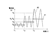
図2は、第1実施形態の磁気軸受の制御装置のバイアス電流選択部25におけるバイアス電流の選択方法を説明する図である。具体的には、図2は、制御電流生成部24からの制御電流信号40の一例のある時間帯の波形と、その時間帯の制御電流信号40に対応するバイアス電流信号41を示す図である。尚、図2において、○は、その点を含まないことを示し、●は、その点を含むことを示している。
FIG. 2 is a diagram illustrating a bias current selection method in the bias
図2に示す例においては、回転軸4の回転中において(時間経過とともに)、制御電流信号40が変化している。
In the example shown in FIG. 2, the control
詳しくは、図2において、時間t1からt2まで(t1を含む一方、t2を含まない)の間において、制御電流信号40は、予め定められた第1閾値A1(A)(図示しない)と、第1閾値A1よりも大きく、かつ、予め定められた第2閾値A2(A)との間に位置していて、バイアス電流選択部25が、バイアス電流として、値が下から2番目のB2(A)であるレベル2のバイアス電流を選択し、バイアス電流選択部25からの信号を受けたバイアス電流生成部23が、レベル2のバイアス電流を生成する。
Specifically, in FIG. 2, during a period from time t1 to time t2 (including t1, but not including t2), the control
次に、時間t2において、制御電流信号40の値は、第2閾値A2の値と同一になり、この時、バイアス電流選択部25が、バイアス電流を、値が下から3番目のB3(A)であるレベル3のバイアス電流値に選択し、レベル3のバイアス電流を生成することを示す信号を、バイアス電流生成部23に出力する。すると、バイアス電流生成部23が、レベル3のバイアス電流を生成する。
Next, at time t2, the value of the control
このように、バイアス電流選択部25は、制御電流生成部24からの制御電流と、所定の閾値との比較結果に基づいて、第1バイアス電流としてのレベル2のバイアス電流または第2バイアス電流としてのレベル3のバイアス電流を選択するようになっている。また、レベル3のバイアス電流は、レベル2のバイアス電流よりも大きく、バイアス電流選択部25は、制御電流の値が所定の閾値より小さい値であるとき、レベル2のバイアス電流を選択する一方、制御電流の値が所定の閾値以上の値になったとき、レベル3のバイアス電流を選択するようになっている。
As described above, the bias
時間t2からt3まで(t2を含む一方、t3を含まない)の間において、制御電流信号40は、予め定められた第2閾値A2と、第2閾値A2よりも大きく、かつ、第3閾値A3(A)との間に位置していて、バイアス電流選択部25が、バイアス電流として、レベル3のバイアス電流値を選択し、バイアス電流生成部23が、レベル3のバイアス電流を生成する。
During the period from time t2 to t3 (including t2, but not including t3), the control
次に、時間t3において、制御電流信号40の値は、第3閾値A3(A)の値と同一になり、この時、バイアス電流選択部25が、バイアス電流を、値が下から4番目のB4(A)であるレベル4のバイアス電流値に選択し、レベル4のバイアス電流を生成することを示す信号を、バイアス電流生成部23に出力する。すると、バイアス電流生成部23が、レベル4のバイアス電流を生成する。
Next, at time t3, the value of the control
図2に示す時間がt3以上の領域において、制御電流信号40は、第3閾値A3と、第3閾値A3よりも値が大きくて、かつ、予め定められた最大の閾値である第4閾値A4(図示せず)との間に位置していて、バイアス電流選択部25が、バイアス電流として、レベル4のバイアス電流値を選択し、バイアス電流生成部23が、レベル4のバイアス電流を生成するようになっている。
In the region where the time shown in FIG. 2 is t3 or more, the control
第1実施形態の磁気軸受の制御装置では、バイアス電流選択部25は、制御電流信号(この場合、制御電流信号は、制御電流そのものになっている)の大きさに対応するバイアス電流を予め規定している次のバイアス電流テーブルに基づいてバイアス電流を選択するようになっている。
In the magnetic bearing control device of the first embodiment, the bias
すなわち、第1実施形態でバイアス電流選択部25が使用しているバイアス電流テーブルでは、制御電流(制御電流信号)が第1閾値よりも小さいときが、レベル1のバイアス電流(最小のバイアス電流)に対応し、制御電流が第1閾値以上第2閾値未満のときが、レベル2のバイアス電流に対応し、制御電流が第2閾値以上第3閾値未満のときが、レベル3のバイアス電流に対応し、制御電流が第3閾値以上第4閾値未満のときが、レベル4のバイアス電流に対応し、制御電流が第4閾値以上のときが、レベル5のバイアス電流(最大のバイアス電流)に対応する。
That is, in the bias current table used by the bias
図2の例では、制御電流(制御電流信号)が、時間と共に、増大する例を示したが、制御電流が、時間と共に、減少することがあるのは、言うまでもない。この場合は、閾値を所定時間(例えば、10秒)の間、継続的に下回ったときに、バイアス電流のレベルを一つ下げるようにする。 In the example of FIG. 2, the control current (control current signal) increases with time, but it goes without saying that the control current may decrease with time. In this case, the bias current level is lowered by one when the threshold value is continuously lowered for a predetermined time (for example, 10 seconds).
別の言葉でいうと、バイアス電流選択部25は、制御電流生成部24からの制御電流の値が所定時間の間持続して所定の閾値を下まわらないとき、その所定の閾値よりも大きくて、かつ、上記所定の閾値にもっとも近いバイアス電流(第1バイアス電流に相当)を選択する一方、制御電流の値が所定時間の間持続して上記所定の閾値を下まわったとき、上記所定の閾値よりも小さくて、かつ、上記所定の閾値にもっとも近いバイアス電流(第2バイアス電流に相当)を選択するようになっている。
In other words, the bias
すなわち、第1実施形態では、バイアス電流があるレベルのバイアス電流であるカレント(current:現在の、今の)状態を第1状態とするとき、バイアス電流が異なるレベルの値である、第1状態の次の第2状態のバイアス電流を選択する方法として、制御電流の値が、カレント状態の制御電流の値よりも大きくて、かつ、そのカレント状態の制御電流の値に最も近い閾値と同一になった瞬間に、バイアス電流の値を、第1状態のバイアス電流の値よりも1段階大きいバイアス電流に設定する一方、制御電流の値が、カレント状態の制御電流の値よりも小さくて、かつ、そのカレント状態の制御電流の値に最も近い閾値を、所定時間(例えば、10秒)の間、継続的に下回ったときに、バイアス電流の値を、第1状態のバイアス電流の値よりも1段階小さいバイアス電流に設定するようになっている。 That is, in the first embodiment, when the current state where the bias current is a certain level of bias current is set to the first state, the bias current is a value at a different level. As a method of selecting a bias current in the second state next to the control current, the value of the control current is larger than the value of the control current in the current state, and is the same as the threshold value closest to the value of the control current in the current state. At the moment, the bias current value is set to a bias current one step larger than the bias current value in the first state, while the control current value is smaller than the control current value in the current state, and When the threshold value closest to the control current value in the current state is continuously reduced for a predetermined time (for example, 10 seconds), the bias current value is set to be greater than the bias current value in the first state. The bias current is set one step smaller.
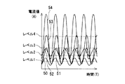
図3は、第1実施形態の磁気軸受の制御装置において、制御電流が、一定の振幅かつ同一周期である場合に、制御電流と、バイアス電流値との関係を示す図である。 FIG. 3 is a diagram showing the relationship between the control current and the bias current value when the control current has a constant amplitude and the same period in the magnetic bearing control device of the first embodiment.
図3に示す例では、制御電流(制御電流信号)50は、レベル1のバイアス電流が選択され、制御電流51および52は、レベル2のバイアス電流が選択され、制御電流53は、レベル3のバイアス電流が選択され、制御電流54は、レベル4のバイアス電流が選択されている。
In the example shown in FIG. 3, the control current (control current signal) 50 is a level 1 bias current, the
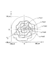
図4は、回転軸4の振れと、バイアス電流との関係の一例を示す図である。詳しくは、回転軸4の軸方向の断面(x軸とy軸とからなる2次元平面)における回転軸4の中心軸の位置と、バイアス電流値との関係を示す図である。尚、図4において、原点P0は、振れがゼロの点を示している。また、図4において、バイアス電流の大きさの尺度としては、原点からの距離が、バイアス電流の大きさに対応している。回転軸4の振れが大きくなると、制御電流大きさが大きくなり、それに伴って、バイアス電流の大きさが大きくなる。 FIG. 4 is a diagram illustrating an example of the relationship between the swing of the rotating shaft 4 and the bias current. Specifically, it is a diagram showing the relationship between the position of the central axis of the rotating shaft 4 and the bias current value in a cross section in the axial direction of the rotating shaft 4 (a two-dimensional plane composed of the x axis and the y axis). In FIG. 4, the origin P 0 indicates a point where the shake is zero. In FIG. 4, as a measure of the magnitude of the bias current, the distance from the origin corresponds to the magnitude of the bias current. When the swing of the rotating shaft 4 increases, the control current increases, and accordingly, the bias current increases.
図4において、振れが、レベル1のバイアス電流のサークル(レベル1の円は含まない)におさまっているときには、レベル1のバイア電流が選択され、振れが、レベル1のバイアス電流のサークル(レベル1の円を含む)を最初に超えた地点からレベル2のバイアス電流のサークル(レベル2の円は含まない)におさまっているときには、レベル2のバイア電流が選択されるようになっている。振れが、レベル2のバイアス電流のサークル(レベル2の円を含む)を最初に超えた地点からレベル3のバイアス電流のサークル(レベル3の円は含まない)におさまっているときには、レベル3のバイアス電流が選択されるようになっている。振れが、レベル3のバイアス電流のサークル(レベル3の円を含む)を最初に超えた地点からレベル4のバイアス電流のサークル(レベル4の円は含まない)におさまっているときには、レベル4のバイアス電流が選択されるようになっている。振れが、レベル4のバイアス電流のサークル(レベル4の円を含む)を最初に超えた地点からレベル5のバイアス電流が選択されるようになっている。
In FIG. 4, when the fluctuation is in the circle of level 1 bias current (not including the circle of level 1), the level 1 via current is selected and the fluctuation is in the circle of level 1 bias current (level The
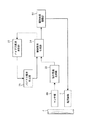
図5は、第1実施形態の磁気軸受の制御装置の制御系の一部を示すブロック図である。 FIG. 5 is a block diagram showing a part of the control system of the magnetic bearing control device of the first embodiment.
図5において、指令電流生成部22は、センサ部60からの信号を受けて指令電流を生成するようになっている。また、制御電流生成部24は、指令電流生成部22からの指令電流と、バイアス電流生成部からのバイアス電流を重ね合わせて(足して)、制御電流を、生成するようになっている。バイアス電流選択部25は、制御電流生成部24から入力された制御電流値と、閾値とを比較して、選択すべきバイアス電流を選択し、選択したバイアス電流を示す信号を、バイアス電流生成部23に出力するようになっている。このように、制御電流によって、バイアス電流が選択され、その選択されたバイアス電流に基づいて、制御電流が生成されるようになっている。磁気軸受駆動部61は、制御電流生成部24からの信号を受けて、磁気軸受6に制御信号を出力するようになっている。
In FIG. 5, the command
一般的に、ターボ分子ポンプは、運転中の殆どの時間において、回転軸が定格回転速度付近で回転するようになっている。したがって、回転軸が、定格回転速度付近で回転しているときの運転コストを低減することができれば、ターボ分子ポンプの運転コストを格段に低減することができることになる。 In general, a turbo molecular pump is configured such that a rotating shaft rotates around a rated rotational speed for most of the time during operation. Therefore, if the operating cost when the rotating shaft rotates around the rated rotational speed can be reduced, the operating cost of the turbo molecular pump can be significantly reduced.
上記第1実施形態のターボ分子ポンプによれば、磁気軸受の制御装置が、バイアス電流を、適宜変更させることができるから、回転軸4が定格回転速度付近で回転していて回転軸4が安定に回転している状態において、バイアス電流を小さく設定することができ、かつ、回転軸4の振れ回りが大きい状態において、バイアス電流を大きく設定することができる。したがって、ターボ分子ポンプの運転コストを格段に低減できると共に、回転軸4の振れが大きい場合において、回転軸4を安定的に制御することができる。 According to the turbo molecular pump of the first embodiment, the control device for the magnetic bearing can change the bias current as appropriate, so that the rotating shaft 4 rotates around the rated rotation speed and the rotating shaft 4 is stable. The bias current can be set small in a state where the rotation shaft is rotating, and the bias current can be set large in a state where the swing of the rotary shaft 4 is large. Therefore, the operating cost of the turbo molecular pump can be remarkably reduced, and the rotating shaft 4 can be stably controlled when the swinging of the rotating shaft 4 is large.
また、上記第1実施形態の磁気軸受の制御装置によれば、バイアス電流選択部25によって、バイアス電流生成部23が一定の第1バイアス電流を生成している第1状態の制御電流に基づいて、バイアス電流が上記第1バイアス電流と異なる一定の第2バイアス電流である上記第1状態の次の第2状態における上記第2バイアス電流を選択することができて、バイアス電流が、回転軸4の振れ(変位)の大きさに無関係に常時一定の値に設定されずに、バイアス電流を、適宜適切な値に切り換えることができる。したがって、例えば、回転軸4の振れ回りが小さくて、回転軸4が安定に回転している状態において、バイアス電流を小さく設定することができるから、回転軸4が安定に回転している状態おいて、消費電流を低減することができる。また、回転軸4の振れ回りが大きい状態において、バイアス電流を大きく設定することができるから、回転軸4の振れ回りが大きい場合であっても、磁気軸受6で回転軸4を安定に支持することができる。
Further, according to the magnetic bearing control device of the first embodiment, the bias
また、上記第1実施形態の磁気軸受の制御装置によれば、バイアス電流選択部25が、制御電流生成部24からの信号と、閾値とを比較することにより、上記第2状態の上記第2バイアス電流を選択するようになっているから、回転軸4が安定に回転している状態において、バイアス電流を容易に小さく設定することができ、かつ、回転軸4の振れ回りが大きい状態において、バイアス電流を容易に大きく設定することができる。
Further, according to the magnetic bearing control device of the first embodiment, the bias
また、上記第1実施形態の磁気軸受の制御装置によれば、バイアス電流選択部25が、制御電流の大きさに対応するバイアス電流を予め規定しているバイアス電流テーブルに基づいてバイアス電流を選択するから、磁気軸受の制御装置が設置される装置の仕様、すなわち、装置の大きさや装置の構成等によって、バイアス電流を容易に変更設定することができて、適切なバイアス電流を容易に生成することができる。
Further, according to the magnetic bearing control device of the first embodiment, the bias
尚、上記第1実施形態のターボ分子ポンプでは、回転軸4が、モータ13のロータとしての役割を兼ねていた。しかしながら、この発明では、回転軸4が、モータのロータの役割を担っていなくても良く、例えば、リング状のロータを、回転軸に固定する形式であっても良い。
In the turbo molecular pump of the first embodiment, the rotating shaft 4 also serves as the rotor of the
図6は、本発明の第2実施形態の磁気軸受の制御装置の制御系の一部を示すブロック図であり、第2実施形態の磁気軸受の制御装置における図5に対応する図である。 FIG. 6 is a block diagram showing a part of a control system of the magnetic bearing control device of the second embodiment of the present invention, and corresponds to FIG. 5 in the magnetic bearing control device of the second embodiment.
第2実施形態の磁気軸受の制御装置は、指令電流制御部が、存在せず、センサ部121が、信号を制御電流生成部124に出力し、制御電流生成部124は、センサ部121からの信号に基づいて、制御信号を生成するようになっている。バイアス電流選択部125は、制御電流生成部124から入力された制御電流と、閾値とを比較して、選択すべきバイアス電流を設定し、選択したバイアス電流を示す信号を、バイアス電流生成部123に出力するようになっている。このように、制御電流によって、制御電流のうちの一定電流成分であるバイアス電流が選択されるようになっている。磁気軸受駆動部127は、制御電流生成部124からの信号を受けて、磁気軸受106に制御信号を出力するようになっている。
In the magnetic bearing control device of the second embodiment, the command current control unit does not exist, the
第2実施形態の磁気軸受の制御装置によれば、第1実施形態と同様に、運転コストを低減できると共に、回転軸104の振れが大きい場合であっても、磁気軸受106によって、回転軸104を安定に制御することができる。
According to the magnetic bearing control device of the second embodiment, the operating cost can be reduced as in the first embodiment, and the
尚、図5および図6に制御系の一部のブロック図が示されている上記第1実施形態および第2実施形態では、バイアス電流生成部23,123が、バイアス電流選択部25,125からの信号を受けて、バイアス電流選択部25,125が選択したバイアス電流を表す信号を、制御電流生成部24,124に出力するようになっていたが、この発明では、バイアス電流選択部が、バイアス電流生成部からの信号と、制御電流生成部からの信号とを受けて、選択したバイアス電流を表す信号を制御電流生成部に出力するようになっていても良い。
In the first embodiment and the second embodiment, in which the block diagrams of a part of the control system are shown in FIGS. 5 and 6, the bias
1 ターボ分子ポンプ本体
2 コントローラ
4,104 回転軸
5 位置検出センサ
6,106 磁気軸受
13 モータ
14 DSP制御装置
22 指令電流生成部
23,123 バイアス電流生成部
24,124 制御電流生成部
25,125 バイアス電流選択部
60,121 センサ部
61,127 磁気軸受駆動部
DESCRIPTION OF SYMBOLS 1 Turbo molecular pump
Claims (7)
上記第1バイアス電流または上記第2バイアス電流と、指令電流とに基づいて制御電流を生成する制御電流生成部と、
上記制御電流生成部からの上記制御電流と、所定の閾値との比較結果に基づいて、上記第1バイアス電流または上記第2バイアス電流を選択して、上記制御電流生成部に出力するバイアス電流選択部と
を備えることを特徴とする磁気軸受の制御装置。 A bias current generator for generating at least a first bias current and a second bias current;
A control current generator for generating a control current based on the first bias current or the second bias current and the command current;
Bias current selection for selecting the first bias current or the second bias current based on a comparison result between the control current from the control current generation unit and a predetermined threshold and outputting the selected current to the control current generation unit And a magnetic bearing control device.
磁気軸受が支持する回転軸の位置を検出するセンサからの出力に基づいて、上記指令電流を生成して、上記制御電流生成部に出力する指令電流生成部を備え、
上記第2バイアス電流は、上記第1バイアス電流よりも大きく、
上記バイアス電流選択部は、上記制御電流の値が上記閾値より小さい値であるとき、上記第1バイアス電流を選択する一方、上記制御電流の値が上記閾値以上の値になったとき、上記第2バイアス電流を選択することを特徴とする磁気軸受の制御装置。 In the magnetic bearing control device according to claim 1,
Based on the output from the sensor that detects the position of the rotary shaft supported by the magnetic bearing, the command current is generated and output to the control current generating unit.
The second bias current is larger than the first bias current,
The bias current selection unit selects the first bias current when the value of the control current is smaller than the threshold value. On the other hand, the bias current selection unit selects the first bias current when the value of the control current becomes equal to or greater than the threshold value. A control apparatus for a magnetic bearing, wherein two bias currents are selected.
磁気軸受が支持する回転軸の位置を検出するセンサからの出力に基づいて、上記指令電流を生成して、上記制御電流生成部に出力する指令電流生成部を備え、
上記第2バイアス電流は、上記第1バイアス電流よりも小さく、
上記バイアス電流選択部は、上記制御電流の値が所定時間の間持続して上記閾値を下まわらないとき、上記第1バイアス電流を選択する一方、上記制御電流の値が所定時間の間持続して上記閾値を下まわったとき、上記第2バイアス電流を選択することを特徴とする磁気軸受の制御装置。 In the magnetic bearing control device according to claim 1,
Based on the output from the sensor that detects the position of the rotary shaft supported by the magnetic bearing, the command current is generated and output to the control current generating unit.
The second bias current is smaller than the first bias current,
The bias current selection unit selects the first bias current when the value of the control current continues for a predetermined time and does not fall below the threshold value, while the value of the control current continues for a predetermined time. And the second bias current is selected when the threshold value falls below the threshold value.
上記制御電流生成部は、磁気軸受が支持する回転軸の位置を検出するセンサからの出力に基づいて、上記制御電流を生成し、
上記第2バイアス電流は、上記第1バイアス電流よりも大きく、
上記バイアス電流選択部は、上記制御電流の値が上記閾値より小さい値であるとき、上記第1バイアス電流を選択する一方、上記制御電流の値が上記閾値以上の値になったとき、上記第2バイアス電流を選択することを特徴とする磁気軸受の制御装置。 In the magnetic bearing control device according to claim 1,
The control current generation unit generates the control current based on an output from a sensor that detects the position of the rotating shaft supported by the magnetic bearing,
The second bias current is larger than the first bias current,
The bias current selection unit selects the first bias current when the value of the control current is smaller than the threshold value. On the other hand, the bias current selection unit selects the first bias current when the value of the control current becomes equal to or greater than the threshold value. A control apparatus for a magnetic bearing, wherein two bias currents are selected.
上記制御電流生成部は、磁気軸受が支持する回転軸の位置を検出するセンサからの出力に基づいて、上記制御電流を生成し、
上記第2バイアス電流は、上記第1バイアス電流よりも小さく、
上記バイアス電流選択部は、上記制御電流の値が所定時間の間持続して上記閾値を下まわらないとき、上記第1バイアス電流を選択する一方、上記制御電流の値が所定時間の間持続して上記閾値を下まわったとき、上記第2バイアス電流を選択することを特徴とする磁気軸受の制御装置。 In the magnetic bearing control device according to claim 1,
The control current generation unit generates the control current based on an output from a sensor that detects the position of the rotating shaft supported by the magnetic bearing,
The second bias current is smaller than the first bias current,
The bias current selection unit selects the first bias current when the value of the control current continues for a predetermined time and does not fall below the threshold value, while the value of the control current continues for a predetermined time. And the second bias current is selected when the threshold value falls below the threshold value.
上記バイアス電流選択部は、上記制御電流の大きさに対応するバイアス電流を予め規定しているバイアス電流テーブルに基づいて上記第1バイアス電流または上記第2バイアス電流を選択することを特徴とする磁気軸受の制御装置。 In the control apparatus of the magnetic bearing as described in any one of Claims 1 thru | or 5,
The bias current selection unit selects the first bias current or the second bias current based on a bias current table that predefines a bias current corresponding to the magnitude of the control current. Bearing control device.
上記回転軸を駆動するモータと、
上記回転軸を、ラジアル方向およびアキシアル方向のうちの少なくとも一方の方向に磁気的に非接触に支持する磁気軸受と、
上記磁気軸受を制御する磁気軸受の制御装置と
を備え、
上記磁気軸受の制御装置は、
少なくとも第1バイアス電流および第2バイアス電流を生成するバイアス電流生成部と、
上記第1バイアス電流または上記第2バイアス電流と、指令電流とに基づいて制御電流を生成する制御電流生成部と、
上記制御電流生成部からの上記制御電流と、所定の閾値との比較結果に基づいて、上記第1バイアス電流または上記第2バイアス電流を選択して、上記制御電流生成部に出力するバイアス電流選択部と
を有し、
上記磁気軸受を、上記制御電流に基づいて制御することを特徴とするターボ分子ポンプ。 A rotation axis;
A motor for driving the rotating shaft;
A magnetic bearing that supports the rotating shaft in a non-contact manner in at least one of a radial direction and an axial direction;
A magnetic bearing control device for controlling the magnetic bearing,
The magnetic bearing control device is:
A bias current generator for generating at least a first bias current and a second bias current;
A control current generator for generating a control current based on the first bias current or the second bias current and the command current;
Bias current selection for selecting the first bias current or the second bias current based on a comparison result between the control current from the control current generation unit and a predetermined threshold and outputting the selected current to the control current generation unit And
A turbo molecular pump characterized in that the magnetic bearing is controlled based on the control current.
Priority Applications (1)
| Application Number | Priority Date | Filing Date | Title |
|---|---|---|---|
| JP2006292646A JP2008106909A (en) | 2006-10-27 | 2006-10-27 | Magnetic bearing control device and turbo-molecular pump |
Applications Claiming Priority (1)
| Application Number | Priority Date | Filing Date | Title |
|---|---|---|---|
| JP2006292646A JP2008106909A (en) | 2006-10-27 | 2006-10-27 | Magnetic bearing control device and turbo-molecular pump |
Publications (1)
| Publication Number | Publication Date |
|---|---|
| JP2008106909A true JP2008106909A (en) | 2008-05-08 |
Family
ID=39440417
Family Applications (1)
| Application Number | Title | Priority Date | Filing Date |
|---|---|---|---|
| JP2006292646A Pending JP2008106909A (en) | 2006-10-27 | 2006-10-27 | Magnetic bearing control device and turbo-molecular pump |
Country Status (1)
| Country | Link |
|---|---|
| JP (1) | JP2008106909A (en) |
Cited By (6)
| Publication number | Priority date | Publication date | Assignee | Title |
|---|---|---|---|---|
| JP2008309151A (en) * | 2007-06-15 | 2008-12-25 | Pfeiffer Vacuum Gmbh | Drive method of device equipped with vacuum pump and the device equipped with vacuum pump |
| JP2010138741A (en) * | 2008-12-10 | 2010-06-24 | Edwards Kk | Vacuum pump |
| JP2010200524A (en) * | 2009-02-26 | 2010-09-09 | Meidensha Corp | Motor controller |
| JP2012503134A (en) * | 2008-09-22 | 2012-02-02 | ソシエテ・ドゥ・メカニーク・マグネティーク | Turbomolecular pump with flexible mounting |
| WO2013046493A1 (en) * | 2011-09-26 | 2013-04-04 | ダイキン工業株式会社 | Electromagnetic bearing and compressor using same |
| CN114060299A (en) * | 2020-08-04 | 2022-02-18 | 广东美的环境电器制造有限公司 | Control method, control circuit, device, equipment and medium of electric fan |
-
2006
- 2006-10-27 JP JP2006292646A patent/JP2008106909A/en active Pending
Cited By (8)
| Publication number | Priority date | Publication date | Assignee | Title |
|---|---|---|---|---|
| JP2008309151A (en) * | 2007-06-15 | 2008-12-25 | Pfeiffer Vacuum Gmbh | Drive method of device equipped with vacuum pump and the device equipped with vacuum pump |
| JP2012503134A (en) * | 2008-09-22 | 2012-02-02 | ソシエテ・ドゥ・メカニーク・マグネティーク | Turbomolecular pump with flexible mounting |
| JP2010138741A (en) * | 2008-12-10 | 2010-06-24 | Edwards Kk | Vacuum pump |
| JP2010200524A (en) * | 2009-02-26 | 2010-09-09 | Meidensha Corp | Motor controller |
| WO2013046493A1 (en) * | 2011-09-26 | 2013-04-04 | ダイキン工業株式会社 | Electromagnetic bearing and compressor using same |
| JP2013068309A (en) * | 2011-09-26 | 2013-04-18 | Daikin Industries Ltd | Magnetic bearing and compressor using the same |
| CN114060299A (en) * | 2020-08-04 | 2022-02-18 | 广东美的环境电器制造有限公司 | Control method, control circuit, device, equipment and medium of electric fan |
| CN114060299B (en) * | 2020-08-04 | 2023-12-29 | 广东美的环境电器制造有限公司 | Control method, control circuit, device, equipment and medium of electric fan |
Similar Documents
| Publication | Publication Date | Title |
|---|---|---|
| JP2008106909A (en) | Magnetic bearing control device and turbo-molecular pump | |
| US7053582B2 (en) | Control magnetic bearing device | |
| US6617734B2 (en) | Magnetic bearing control device | |
| JP2000145774A (en) | Control-type magnetic bearing device | |
| WO2019239682A1 (en) | Magnetic bearing control device and magnetic bearing control method | |
| EP1085225A2 (en) | Magnetic bearing device for motor-combined structure | |
| JP4136385B2 (en) | Magnetic bearing type turbo molecular pump | |
| JP5376199B2 (en) | Flywheel uninterruptible power supply and control method thereof | |
| JP2006022914A (en) | Magnetic bearing device | |
| US11384770B2 (en) | Vacuum pump, and control device of vacuum pump | |
| JP4483431B2 (en) | Turbo molecular pump device | |
| JP4353017B2 (en) | Magnetic bearing device | |
| JP4893353B2 (en) | Centrifugal compressor device, fuel cell compressor, and control method for fuel cell compressor | |
| JP2006009759A (en) | Turbo-molecular pump device | |
| JP2007263250A (en) | Magnetic bearing device | |
| JPH10184586A (en) | Turbo-molecular pump | |
| JP2007138892A (en) | Magnetic bearing type turbo-molecular pump | |
| JP4110305B2 (en) | Magnetic bearing device | |
| JP2005325977A (en) | Magnetic bearing device | |
| JP5076513B2 (en) | Centrifugal compressor device, fuel cell compressor, and control method for the fuel cell compressor | |
| JP2004270778A (en) | Magnetic bearing device | |
| JP3937623B2 (en) | Magnetic bearing device for power storage | |
| JP2001263352A (en) | Magnetic bearing device | |
| JP3470210B2 (en) | Motor control device | |
| JP3564595B2 (en) | Magnetic levitation rotating device |