JP2008096230A - Strain gauge type sensor - Google Patents
Strain gauge type sensor Download PDFInfo
- Publication number
- JP2008096230A JP2008096230A JP2006277059A JP2006277059A JP2008096230A JP 2008096230 A JP2008096230 A JP 2008096230A JP 2006277059 A JP2006277059 A JP 2006277059A JP 2006277059 A JP2006277059 A JP 2006277059A JP 2008096230 A JP2008096230 A JP 2008096230A
- Authority
- JP
- Japan
- Prior art keywords
- axis
- strain gauges
- strain
- strain gauge
- flexible portion
- Prior art date
- Legal status (The legal status is an assumption and is not a legal conclusion. Google has not performed a legal analysis and makes no representation as to the accuracy of the status listed.)
- Pending
Links
Images


Classifications
-
- G—PHYSICS
- G01—MEASURING; TESTING
- G01L—MEASURING FORCE, STRESS, TORQUE, WORK, MECHANICAL POWER, MECHANICAL EFFICIENCY, OR FLUID PRESSURE
- G01L1/00—Measuring force or stress, in general
- G01L1/20—Measuring force or stress, in general by measuring variations in ohmic resistance of solid materials or of electrically-conductive fluids; by making use of electrokinetic cells, i.e. liquid-containing cells wherein an electrical potential is produced or varied upon the application of stress
- G01L1/22—Measuring force or stress, in general by measuring variations in ohmic resistance of solid materials or of electrically-conductive fluids; by making use of electrokinetic cells, i.e. liquid-containing cells wherein an electrical potential is produced or varied upon the application of stress using resistance strain gauges
- G01L1/2206—Special supports with preselected places to mount the resistance strain gauges; Mounting of supports
- G01L1/2218—Special supports with preselected places to mount the resistance strain gauges; Mounting of supports the supports being of the column type, e.g. cylindric, adapted for measuring a force along a single direction
- G01L1/2225—Special supports with preselected places to mount the resistance strain gauges; Mounting of supports the supports being of the column type, e.g. cylindric, adapted for measuring a force along a single direction the direction being perpendicular to the central axis
-
- G—PHYSICS
- G01—MEASURING; TESTING
- G01L—MEASURING FORCE, STRESS, TORQUE, WORK, MECHANICAL POWER, MECHANICAL EFFICIENCY, OR FLUID PRESSURE
- G01L1/00—Measuring force or stress, in general
- G01L1/20—Measuring force or stress, in general by measuring variations in ohmic resistance of solid materials or of electrically-conductive fluids; by making use of electrokinetic cells, i.e. liquid-containing cells wherein an electrical potential is produced or varied upon the application of stress
- G01L1/22—Measuring force or stress, in general by measuring variations in ohmic resistance of solid materials or of electrically-conductive fluids; by making use of electrokinetic cells, i.e. liquid-containing cells wherein an electrical potential is produced or varied upon the application of stress using resistance strain gauges
- G01L1/2206—Special supports with preselected places to mount the resistance strain gauges; Mounting of supports
- G01L1/2231—Special supports with preselected places to mount the resistance strain gauges; Mounting of supports the supports being disc- or ring-shaped, adapted for measuring a force along a single direction
- G01L1/2237—Special supports with preselected places to mount the resistance strain gauges; Mounting of supports the supports being disc- or ring-shaped, adapted for measuring a force along a single direction the direction being perpendicular to the central axis
-
- G—PHYSICS
- G01—MEASURING; TESTING
- G01L—MEASURING FORCE, STRESS, TORQUE, WORK, MECHANICAL POWER, MECHANICAL EFFICIENCY, OR FLUID PRESSURE
- G01L5/00—Apparatus for, or methods of, measuring force, work, mechanical power, or torque, specially adapted for specific purposes
- G01L5/16—Apparatus for, or methods of, measuring force, work, mechanical power, or torque, specially adapted for specific purposes for measuring several components of force
- G01L5/161—Apparatus for, or methods of, measuring force, work, mechanical power, or torque, specially adapted for specific purposes for measuring several components of force using variations in ohmic resistance
- G01L5/162—Apparatus for, or methods of, measuring force, work, mechanical power, or torque, specially adapted for specific purposes for measuring several components of force using variations in ohmic resistance of piezoresistors
-
- G—PHYSICS
- G01—MEASURING; TESTING
- G01L—MEASURING FORCE, STRESS, TORQUE, WORK, MECHANICAL POWER, MECHANICAL EFFICIENCY, OR FLUID PRESSURE
- G01L5/00—Apparatus for, or methods of, measuring force, work, mechanical power, or torque, specially adapted for specific purposes
- G01L5/16—Apparatus for, or methods of, measuring force, work, mechanical power, or torque, specially adapted for specific purposes for measuring several components of force
- G01L5/161—Apparatus for, or methods of, measuring force, work, mechanical power, or torque, specially adapted for specific purposes for measuring several components of force using variations in ohmic resistance
- G01L5/1627—Apparatus for, or methods of, measuring force, work, mechanical power, or torque, specially adapted for specific purposes for measuring several components of force using variations in ohmic resistance of strain gauges
Abstract
Description
本発明は、多軸成分の力などを検出することができる歪みゲージ式センサに関する。 The present invention relates to a strain gauge sensor capable of detecting a force of a multi-axis component or the like.
特許文献1には、円盤形状のフランジから成る第1部材及び第2部材を備えた6軸センサが記載されている。上記の第1部材および第2部材は、それぞれ対向する4つのダイヤフラムを有している。そして、各ダイヤフラムには、8個の歪みゲージが配置されている。そして、各歪みゲージが配線により接続されることでブリッジ回路が構成されており、各歪みゲージの抵抗値の変化に基づいて力及びモーメントが検出される。
しかしながら、X軸方向、Y軸方向及びZ軸方向の力を検出するためのブリッジ回路が別々に設けられている場合には、ブリッジ回路のみならず、ブリッジ回路からリード線を引き出すためのランドを含めた回路構成が必要であり、非常に複雑なものとなる。特にセンサの小型化を図る場合には、狭い領域内において上記の回路を構成する必要があるが困難である。そのため、歪みゲージの数は極力少なくし、回路構成を簡略化するのが好ましい。 However, when a bridge circuit for detecting forces in the X-axis direction, the Y-axis direction, and the Z-axis direction is separately provided, not only the bridge circuit but also a land for drawing out the lead wire from the bridge circuit. A circuit configuration including the above is necessary and becomes very complicated. In particular, when downsizing the sensor, it is necessary to configure the circuit in a narrow area, but it is difficult. Therefore, it is preferable to reduce the number of strain gauges as much as possible and simplify the circuit configuration.
そこで、本発明の目的は、小型化が可能な歪みゲージ式センサを提供することである。 Therefore, an object of the present invention is to provide a strain gauge type sensor that can be miniaturized.
本発明の歪みゲージ式センサは、一平面上において2個又は4個の歪みゲージが一直線上に配置された第1可撓部を有する第1部材と、前記第1可撓部に対向する第2可撓部を有する第2部材と、前記第1可撓部と前記第2可撓部とを連結する連結体とを備え、前記2個又は4個の歪みゲージのそれぞれの抵抗値の変化に基づいて前記平面上の前記2個又は4個の歪みゲージの配列方向に平行な方向の力及び前記平面に垂直な方向の力を検出することを特徴としている。 The strain gauge type sensor of the present invention includes a first member having a first flexible part in which two or four strain gauges are arranged on a straight line, and a first member facing the first flexible part. A second member having two flexible parts, and a connecting body that connects the first flexible part and the second flexible part, and changes in resistance values of the two or four strain gauges. Based on the above, a force in a direction parallel to the arrangement direction of the two or four strain gauges on the plane and a force in a direction perpendicular to the plane are detected.
この構成によると、一平面上に配置された2個又は4個の歪みゲージを用いて、平面上の2個又は4個の歪みゲージの配列方向に平行な方向の力及び平面に垂直な方向の力を検出することができる。そのため、上記の2つの方向の力を検出するための歪みゲージをそれぞれ別々に設ける必要がなく、2個又は4個の歪みゲージを共用することで、上記の2つの方向の力を検出するための歪みゲージの数を少なくすることができる。従って、ブリッジ回路及びそのブリッジ回路からリード線を引き出すためのランドを含めた回路構成が簡略化されるので、センサの小型化が容易になる。 According to this configuration, using two or four strain gauges arranged on one plane, a force in a direction parallel to the arrangement direction of the two or four strain gauges on the plane and a direction perpendicular to the plane Can be detected. Therefore, it is not necessary to separately provide strain gauges for detecting the forces in the above two directions, and the forces in the above two directions are detected by sharing two or four strain gauges. The number of strain gauges can be reduced. Accordingly, since the circuit configuration including the bridge circuit and the land for drawing out the lead wire from the bridge circuit is simplified, the sensor can be easily downsized.
本発明の歪みゲージ式センサでは、前記連結体の外径は前記第1可撓部の外径よりも小さく、前記2個又は4個の歪みゲージは、前記第1可撓部の外端部及び前記連結体の外端部に対応した位置に配置されていてもよい。 In the strain gauge type sensor of the present invention, the outer diameter of the coupling body is smaller than the outer diameter of the first flexible portion, and the two or four strain gauges are the outer end portions of the first flexible portion. And it may be arranged at a position corresponding to the outer end of the connector.
この構成によると、歪みゲージが第1可撓部において最も大きな歪みが発生する位置に配置されるので、センサ感度が向上する。 According to this configuration, since the strain gauge is disposed at a position where the largest strain is generated in the first flexible portion, the sensor sensitivity is improved.
本発明の歪みゲージ式センサでは、前記2個又は4個の歪みゲージは、前記第1可撓部の中心位置に対して対称に配置されていてもよい。 In the strain gauge sensor of the present invention, the two or four strain gauges may be arranged symmetrically with respect to the center position of the first flexible portion.
本発明の歪みゲージ式センサでは、前記2個又は4個の歪みゲージ、前記第1可撓部、前記第2可撓部及び前記連結体の組が複数設けられており、前記複数組の前記2個又は4個の歪みゲージ、前記第1可撓部、前記第2可撓部及び前記連結体は、前記平面上の中心点を中心に等角度おき且つ前記中心点から等距離に配置されていてもよい。 In the strain gauge type sensor of the present invention, a plurality of sets of the two or four strain gauges, the first flexible portion, the second flexible portion, and the coupling body are provided, Two or four strain gauges, the first flexible portion, the second flexible portion, and the coupling body are arranged at equal angles around the center point on the plane and at equal distances from the center point. It may be.
この構成によると、多軸成分の力を検出することが可能であり、多軸方向の力、モーメントを検出することができる。 According to this configuration, it is possible to detect multiaxial component forces, and it is possible to detect multiaxial forces and moments.
本発明の歪みゲージ式センサでは、前記角度は90度であってもよい。 In the strain gauge sensor of the present invention, the angle may be 90 degrees.
この構成によると、互いに直交する方向成分及びそれに直交する方向成分の力、モーメントを検出することができる。 According to this configuration, it is possible to detect the direction component orthogonal to each other and the force and moment of the direction component orthogonal to the direction component.
本発明の歪みゲージ式センサでは、前記複数組の前記2個又は4個の歪みゲージ及び前記第1可撓部は、前記中心点を原点とするX軸およびY軸上の正方向および負方向にそれぞれ対応した位置に配置されていてもよい。 In the strain gauge type sensor according to the present invention, the plurality of sets of the two or four strain gauges and the first flexible portion may have positive and negative directions on the X axis and the Y axis with the center point as an origin. It may be arranged at a position corresponding to each.
この構成によると、平面上の中心点を原点とするX軸方向及びY軸方向の力、モーメントを検出することができる。 According to this configuration, it is possible to detect forces and moments in the X-axis direction and the Y-axis direction with the center point on the plane as the origin.
本発明の歪みゲージ式センサでは、X軸上の正方向および負方向に対応した位置に配置された前記2個又は4個の歪みゲージはX軸と直交する方向に配列されていると共に、Y軸上の正方向および負方向に対応した位置に配置された前記2個又は4個の歪みゲージはY軸と直交する方向に配列されていてもよい。 In the strain gauge type sensor of the present invention, the two or four strain gauges arranged at positions corresponding to the positive direction and the negative direction on the X axis are arranged in a direction perpendicular to the X axis, and Y The two or four strain gauges arranged at positions corresponding to the positive direction and the negative direction on the axis may be arranged in a direction perpendicular to the Y axis.
この構成によると、平面上の中心点を原点とするX軸方向及びY軸方向の力、モーメントを容易に検出することができる。 According to this configuration, it is possible to easily detect forces and moments in the X-axis direction and the Y-axis direction with the center point on the plane as the origin.
本発明の歪みゲージ式センサでは、前記角度は120度であってもよい。 In the strain gauge sensor of the present invention, the angle may be 120 degrees.
この構成によると、角度が90度の場合と比較して、平面上に配置される電極や第1部材及び第2部材の可撓部の数が少なくなるので、製造コストを低減できる。 According to this configuration, as compared with the case where the angle is 90 degrees, the number of electrodes arranged on the plane and the number of flexible portions of the first member and the second member are reduced, so that the manufacturing cost can be reduced.
本発明の歪みゲージ式センサでは、前記複数組の前記2個又は4個の歪みゲージ及び前記第1可撓部は、前記中心点を原点とするX軸正方向からY軸負方向に30度をなす第1線上に対応した位置、X軸負方向からY軸負方向に30度をなす第2線上に対応した位置およびY軸上の正方向に対応した位置にそれぞれ配置されていてもよい。 In the strain gauge type sensor of the present invention, the plurality of sets of the two or four strain gauges and the first flexible portion may be 30 degrees from the positive X-axis direction to the negative Y-axis direction with the center point as the origin. May be arranged at a position corresponding to the first line forming the position, a position corresponding to the second line forming 30 degrees from the X axis negative direction to the Y axis negative direction, and a position corresponding to the positive direction on the Y axis. .
本発明の歪みゲージ式センサでは、第1線上に対応した位置に配置された前記2個又は4個の歪みゲージは第1線と直交する方向に配列されており、第2線上に対応した位置に配置された前記2個又は4個の歪みゲージは第2線と直交する方向に配列されており、Y軸上の正方向に対応した位置に配置された前記2個又は4個の歪みゲージはX軸と直交する方向に配列されていてもよい。 In the strain gauge sensor of the present invention, the two or four strain gauges arranged at positions corresponding to the first line are arranged in a direction orthogonal to the first line, and positions corresponding to the second line. The two or four strain gauges arranged on the Y axis are arranged in a direction orthogonal to the second line, and the two or four strain gauges are arranged at positions corresponding to the positive direction on the Y axis. May be arranged in a direction orthogonal to the X axis.
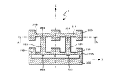
以下、本発明の好適な実施の形態について、図面を参照しつつ説明する。図1は本発明の第1の実施の形態に係る歪みゲージ式センサの中央縦断面正面図である。図2は、図1のA−A線における断面図である。図3は、歪みゲージの配置を示す図である。 Hereinafter, preferred embodiments of the present invention will be described with reference to the drawings. FIG. 1 is a central longitudinal sectional front view of a strain gauge type sensor according to a first embodiment of the present invention. 2 is a cross-sectional view taken along line AA in FIG. FIG. 3 is a diagram showing an arrangement of strain gauges.
図1の歪みゲージ式センサ1は、十分な剛性を有する固定部300に固定された第1フランジ100と、第1フランジ100に対向するように配置された第2フランジ200とを有している。固定部300は円盤形状であって、その上面の中央部は凹部になっている。そして、固定部300は、その周辺部で第1フランジ100を支持する構造になっている。第1フランジ100および第2フランジ200は、金属などで形成された円盤形状のフランジから構成されている。第1フランジ100には、4つの肉薄の可撓部111〜114が設けられており、各可撓部111〜114の中央部には連結体121〜124が形成されている。同様に、第2フランジ200には、4つの肉薄の可撓部211〜214が設けられており、各可撓部211〜214の中央部には連結体221〜224が形成されている(図2参照)。
The strain
そして、連結体121〜124と連結体221〜224とがボルト等の適当な手段を用いて連結されており、第1フランジ100の可撓部111〜114及び連結体121〜124と、第2フランジ200の可撓部211〜214及び連結体221〜224とは、ほぼ対称となっている。ここで、連結体121〜124と連結体221〜224とはそれぞれ強固に連結されているため、第1フランジ100と第2フランジ200とは一体の部材と見なすことができる。
And the connection bodies 121-124 and the connection bodies 221-224 are connected using suitable means, such as a volt | bolt, the flexible parts 111-114 of the
第1フランジ100の可撓部111〜114は、図3に示すように、X軸およびY軸上の正方向および負方向にそれぞれ配置されている。第1フランジ100の下面であり且つ固定部300の凹部に対向した位置には、一平面上に配置された複数の歪みゲージR11〜R14、R21〜R24、R31〜R34、R41〜R44が配置されている。
As shown in FIG. 3, the
第1フランジ100の可撓部111〜114は、それぞれ一直線上に配置された4個の歪みゲージを備えている。各可撓部111〜114の4個の歪みゲージの配置位置は、図3に示すように、X軸正方向およびX軸負方向に配置された可撓部111〜113においては、その中心位置を通り且つY軸に平行な線上における薄肉部分の外縁部と内縁部である。一方、Y軸正方向およびY軸負方向に配置された可撓部112〜114においては、その中心位置を通り且つX軸に平行な線上における薄肉部分の外縁部と内縁部である。すなわち、可撓部111の歪みゲージR11、R12と歪みゲージR13、R14、及び、可撓部113の歪みゲージR31、R32と歪みゲージR33、R34はX軸に対して線対称に配置されている。また、可撓部112の歪みゲージR21、R22と歪みゲージR23、R24、及び、可撓部114の歪みゲージR41、R42と歪みゲージR43、R44はY軸に対して線対称に配置されている。このように、各可撓部111〜114において、歪みゲージは最も大きな歪みが発生する位置に貼り付けられている。なお、歪みゲージのリード線の図示は省略している。
The
このように、歪みゲージ式センサ1には、4個の歪みゲージ、第1フランジ100の可撓部、第2フランジ200の可撓部及び連結体の組を4組設けられている。そして、各組の4個の歪みゲージ、第1フランジ100の可撓部、第2フランジ200の可撓部及び連結体は、Z軸を中心に90度おき且つZ軸から等距離に配置されている。
Thus, the strain
歪みゲージとしては、金属箔歪みゲージや金属線歪みゲージを用いている。歪みゲージは一種の抵抗体であり、歪みの発生する場所に貼り付けて使用する検出素子である。歪みの発生により抵抗値が変化することにより、歪みεを測定することができる。一般には、引張りによる歪みεに対しては抵抗値が大きくなり、圧縮による歪みεに対しては抵抗値が小さくなる比例特性を持っている。また、通常は材料が歪みεに対して応力σが比例する弾性域で使用する。本実施形態でも第1フランジ100の弾性域で使用するものとしている。
As the strain gauge, a metal foil strain gauge or a metal wire strain gauge is used. A strain gauge is a kind of resistor, and is a detection element that is used by being attached to a place where distortion occurs. The strain ε can be measured by changing the resistance value due to the occurrence of the strain. Generally, the resistance value increases with respect to the strain ε due to tension, and the resistance value decreases with respect to the strain ε due to compression. In general, the material is used in an elastic region in which the stress σ is proportional to the strain ε. Also in this embodiment, the
ここで、歪みゲージは、一般的な樹脂の上に金属箔のパターンを形成したものでもよい。また、第1フランジの下面に酸化シリコンなどの絶縁膜を形成し、その上にクロムまたはニッケルなどの合金の金属薄膜、酸化クロムなどの金属薄膜で歪みゲージを形成してもよい。この場合、歪みゲージを形成する面が平坦な一平面である場合には、フォトリソグラフィーの技術を利用して、スパッタリング装置などでプロセス的に形成可能であり、量産に適する。また、歪みを検出する素子としては、ピエゾ抵抗素子、感圧抵抗体、感圧抵抗インクなども利用可能であり、歪みを検出する素子であれば、これらに限られない。 Here, the strain gauge may be formed by forming a metal foil pattern on a general resin. Alternatively, an insulating film such as silicon oxide may be formed on the lower surface of the first flange, and a strain gauge may be formed thereon using a metal thin film of an alloy such as chromium or nickel, or a metal thin film such as chromium oxide. In this case, when the surface on which the strain gauge is formed is a flat surface, it can be formed in a process using a sputtering apparatus or the like using a photolithography technique, and is suitable for mass production. In addition, as an element for detecting strain, a piezoresistive element, a pressure sensitive resistor, a pressure sensitive resistance ink, and the like can be used, and the element is not limited as long as it is an element for detecting strain.
上述したように、第1フランジ100には可撓部111〜114が形成され、第2フランジ200には可撓部211〜214が形成されているので、第2フランジ200に力が作用すると、連結体121〜124及び連結体221〜224を介して、可撓部111〜114に力が伝わり、3次元空間の力の大きさ及び方向に応じて可撓部111〜114に歪みが発生する。よって、この歪みゲージ式センサ1は3次元空間の直交する3軸の力とその軸回りのモーメントを測定するための6軸力覚センサとして機能する。
As described above, since the
次に、各軸方向ごとに力とモーメントを検出する原理を説明する。以下、第1フランジが固定された状態で、第2フランジ200に力やモーメントが作用するものとする。
Next, the principle of detecting force and moment for each axial direction will be described. Hereinafter, it is assumed that force and moment act on the
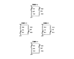
図4に、X軸方向の力Fxを加えたときの歪みゲージ式センサ1の状態を示す。このときは、第1フランジ100の可撓部111〜114及び第2フランジ200の可撓部211〜214は、図示したように変位し、歪みが検出される。図5に歪みゲージの抵抗値の変化を示す。図中、(+)は引張歪みを検出することによる抵抗値の増加を、(−)は圧縮歪みを検出することによる抵抗値の減少を示す。どちらの記号も無い歪みゲージは歪みが殆ど発生せず抵抗値の変化が殆ど無いことを示す。
FIG. 4 shows a state of the strain
次に、Y軸方向の力Fyを加えたときは、X軸方向の力Fxを加えたときの状態を90度ずらして考えればよいので、ここでは省略する。 Next, when the force Fy in the Y-axis direction is applied, the state when the force Fx in the X-axis direction is applied may be shifted by 90 degrees, and the description is omitted here.
図6にZ軸方向の力Fzを加えたときの歪みゲージ式センサ1の状態を示す。図7に、このときの各歪みゲージの変化を示す。
FIG. 6 shows a state of the strain
図8にY軸のモーメントMyを加えたときの歪みゲージ式センサ1の状態を示す。このときは、可撓部111が固定部300側に押し出され、可撓部113が固定部300から離隔するように変位する。図9に、このときの各歪みゲージの変化を示す。
FIG. 8 shows the state of the
次に、X軸のモーメントMxを加えたときは、Y軸のモーメントMyを加えたときの状態を90度ずらして考えればよいので、ここでは省略する。 Next, when the X-axis moment Mx is applied, the state when the Y-axis moment My is applied may be shifted by 90 degrees, and is omitted here.
また、Z軸のモーメントMzを加えたときは、連結体121〜124及び連結体221〜224がZ軸を中心とする円周に沿って同じ回転方向に傾倒するように変位する。
Further, when the Z-axis moment Mz is applied, the connecting
表1に、上述した各力およびモーメントに対する各歪みゲージの抵抗値の変化を示す。表中、+は抵抗値の増加、−は抵抗値の減少を示し、符号無しは抵抗値が殆ど変化しないことを示す。また、反対方向の力やモーメントの場合は符号が逆になる。 Table 1 shows changes in resistance values of the strain gauges with respect to the forces and moments described above. In the table, + indicates an increase in resistance value, − indicates a decrease in resistance value, and no sign indicates that the resistance value hardly changes. In the case of force or moment in the opposite direction, the sign is reversed.

以上の性質を利用して、数式1の演算を行うことにより各力およびモーメントを検出することができる。
Utilizing the above properties, each force and moment can be detected by performing the calculation of
上記の数式1を別の表現で記載すると、数式2になる。
When
以上のことから、可撓部111、113に配置された歪みゲージR11〜R14、R31〜R34は、Y軸方向の力とZ軸方向の力とを検出する機能を有しており、可撓部112、114に配置された歪みゲージR21〜R24、R41〜R44は、X軸方向の力とZ軸方向の力とを検出する機能を有していることが分かる。
From the above, the strain gauges R11 to R14 and R31 to R34 arranged in the
また、数式1の演算は、歪みゲージの抵抗値を直接検出して行ってもよいし、各抵抗値を電圧又は電流に変換して行ってもよい。また、マイクロコンピュータやパソコンのAD変換機能を利用して一旦デジタル値に変換してから行ってもよい。なお、演算方法は数式1に限られないのは勿論である。
The calculation of
また、図10は、数式1の演算を行うために利用可能なブリッジ回路を示す図である。各可撓部111〜114では、ハーフブリッジ回路が各2回路形成されており、定電圧で駆動している。そして、歪みゲージR11、R12間の節点電圧をY1Pとし、歪みゲージR13、R14間の節点電圧をY1Nとする。また同様に、図10に示すように、節点電圧Y2P、Y2N、Y3P、Y3N、Y4P、Y4Nを定める。これらの節点電圧を図示しないリード線で引き出し、図11に示すように、OPアンプなどの演算器に入力すれば、Fx、Fy、Fz、Mx、My、Mzを算出することができる。なお、各節点電圧を増幅してからAD変換器に入力し、マイクロコンピュータやパソコンなどで図8に相当する演算を行ってもよい。
FIG. 10 is a diagram illustrating a bridge circuit that can be used to perform the calculation of
以上説明したように、本実施の形態の歪みゲージ式センサ1では、一平面上に配置された4個の歪みゲージを用いて、平面上の歪みゲージの配列方向に平行な方向の力及び平面に垂直な方向の力を検出することができる。そのため、上記の2つの方向の力を検出するための歪みゲージをそれぞれ別々に設ける必要がなく、4個の歪みゲージを共用することで、上記の2つの方向の力を検出するための歪みゲージの数を少なくすることができる。従って、ブリッジ回路及びそのブリッジ回路からリード線を引き出すためのランドを含めた回路構成が簡略化されるので、センサの小型化が容易になる。
As described above, in the strain
次に、本発明の第2の実施の形態について、図12〜図14を参照して説明する。図12は本発明の第2の実施の形態に係る歪みゲージ式センサの歪みゲージの配置を示す図である。図13は、図12の歪みゲージ式センサで演算を行うために利用可能なブリッジ回路を示す図である。図14は、X方向、Y方向及びZ方向のベクトルへの分解を示す図である。 Next, a second embodiment of the present invention will be described with reference to FIGS. FIG. 12 is a diagram showing the arrangement of strain gauges of the strain gauge type sensor according to the second embodiment of the present invention. FIG. 13 is a diagram showing a bridge circuit that can be used to perform calculations with the strain gauge type sensor of FIG. FIG. 14 is a diagram illustrating decomposition into vectors in the X, Y, and Z directions.
本実施の形態の歪みゲージ式センサが、第1の実施の形態の歪みゲージ式センサ1と大きく異なる点は、第1フランジ100の下面における歪みゲージの配置及び数である。つまり、第1の実施の形態では、4組の可撓部及び4個の歪みゲージが90度おきに配置されているが、本実施の形態では、3組の可撓部及び4個の歪みゲージが120度おきに配置されている。そのため、第1フランジ及び第2フランジは、3組の可撓部に対応した位置に配置された3つの連結体を有している。
The strain gauge type sensor of the present embodiment is greatly different from the strain
本実施の形態では、3個の可撓部111〜113が、X軸正方向からY軸負方向に30度をなす第1線上に対応した位置、Y軸上の正方向に対応した位置およびX軸負方向からY軸負方向に30度をなす第2線上に対応した位置にそれぞれ配置されている。そして、可撓部111に配置された4個の歪みゲージR11〜R14は第1線と直交する方向に配列されており、可撓部112に配置された4個の歪みゲージR21〜R24はY軸と直交する方向に配列されており、可撓部113に配置された4個の歪みゲージR31〜R34は第2線と直交する方向に配列されている。
In the present embodiment, the three
第2フランジ200に対して、第1の実施の形態と同様に、Fx、Fy、Fz、Mx、My、Mzの力やモーメントを作用させると、表2のように、各歪みゲージの抵抗値が変化する。
When the forces and moments of Fx, Fy, Fz, Mx, My, and Mz are applied to the
表中、+は抵抗値の増加、−は抵抗値の減少を示し、符号無しは抵抗値が殆ど変化しないことを示す。また、反対方向の力やモーメントの場合は符号が逆になる。 In the table, + indicates an increase in resistance value, − indicates a decrease in resistance value, and no sign indicates that the resistance value hardly changes. In the case of force or moment in the opposite direction, the sign is reversed.
各可撓部111〜113では、図13に示すように、ハーフブリッジ回路が各2回路形成されており、定電圧で駆動している。そして、歪みゲージR11、R12間の節点電圧をV11とし、歪みゲージR13、R14間の節点電圧をV12とする。また同様に、節点電圧V21、V22、V31、V32を定める。これらの節点電圧を図示しないリード線で引き出し、第1の実施の形態と同様に、OPアンプなどの演算器に入力すれば、Fx、Fy、Fz、Mx、My、Mzを算出することができる。
In each of the
ここで、歪みゲージR11〜R14、R21〜R24、R31〜R34の抵抗値の変化から、連結体を傾倒させる力とZ軸方向に作用する力とを検出できるが、連結体を歪みゲージの配列方向に傾倒させる場合に、歪みゲージの抵抗値が最も大きく変化し、センサ感度が最もよくなる。 Here, from the change in the resistance values of the strain gauges R11 to R14, R21 to R24, R31 to R34, the force for tilting the coupled body and the force acting in the Z-axis direction can be detected. When tilting in the direction, the resistance value of the strain gauge changes the most, and the sensor sensitivity is the best.
また、歪みゲージR11〜R14、R21〜R24、R31〜R34の感度の方向性を考慮すると、図14のようなベクトル図になる。従って、可撓部111の連結体121を歪みゲージの配列方向に傾倒させる力は、V12−V11となり、可撓部111の連結体121のZ軸方向に作用する力は、V11+V12となり、可撓部112の連結体122を歪みゲージの配列方向に傾倒させる力は、V22−V22となり、可撓部112の連結体122のZ軸方向に作用する力は、−(V21+V22)となり、可撓部113の連結体123を歪みゲージの配列方向に傾倒させる力は、V32−V31となり、可撓部113の連結体123のZ軸方向に作用する力は、V31+V32となる。
Further, considering the directionality of the sensitivity of the strain gauges R11 to R14, R21 to R24, and R31 to R34, the vector diagram as shown in FIG. Therefore, the force that tilts the connecting
ここで、可撓部111の連結体121のZ軸方向に作用する力と、可撓部113の連結体123のZ軸方向に作用する力とは、連結体が固定部300から離隔する方向つまりZ軸正方向の力が作用した場合に、V11+V12、V31+V32は増加するが、可撓部112の連結体122のZ軸方向に作用する力は、連結体が固定部300から離隔する方向つまりZ軸正方向の力が作用した場合に、V21+V22は減少するので、極性を考慮して符号「−」を付加している。
Here, the force acting in the Z-axis direction of the
上記の数式2の考え方及び図14のベクトル図から、数式3の演算を行うことにより各力およびモーメントを検出することができる。 Each force and moment can be detected by performing the calculation of Formula 3 from the concept of Formula 2 and the vector diagram of FIG.
これにより、第1の実施の形態と同様の効果を得ることができる。 Thereby, the effect similar to 1st Embodiment can be acquired.
以上、本発明の好適な実施の形態について説明したが、本発明は上述の実施の形態に限られるものではなく、特許請求の範囲に記載した限りにおいて様々な設計変更が可能なものである。例えば、上述の第1及び第2の実施の形態では、6軸の力およびモーメントを検出する歪みゲージ式センサについて説明しているが、これに限らず、6軸の加速度および角加速度を検出する歪みゲージ式センサであってもよいし、X軸とY軸との2方向の力だけを検出する2軸センサとして使用してもよい。また、各組の4個の歪みゲージ、第1フランジ100の可撓部、第2フランジ200の可撓部及び連結体は、Z軸を中心に90度おき又は120度おき且つZ軸から等距離に配置されているが、これには限られない。また、可撓部111〜114及び可撓部211〜214の厚さや大きさは異なっていてもよいが同じであることが好ましい。また、第1フランジ100と第2フランジ200とは異なる大きさであってもよいし、シリコンゴムや合成樹脂で形成してもよい。各連結体は各フランジと同一部材であってもよい。
The preferred embodiments of the present invention have been described above. However, the present invention is not limited to the above-described embodiments, and various design changes can be made as long as they are described in the claims. For example, in the first and second embodiments described above, a strain gauge type sensor that detects six-axis forces and moments has been described. However, the present invention is not limited to this, and six-axis acceleration and angular acceleration are detected. It may be a strain gauge type sensor or may be used as a biaxial sensor that detects only forces in two directions of the X axis and the Y axis. The four strain gauges of each set, the flexible portion of the
また、上述の第1及び第2の実施の形態では、各可撓部は一直線上に配置された4個の歪みゲージを有しているが、各可撓部は一直線上に配置された2個の歪みゲージを有していてもよい。従って、第1の実施の形態の図10において、例えば、R12、R13、R22、R23、R32、R33、R42、R43を固定抵抗に置き換え、1アクティブハーフブリッジにしても力及びモーメントを検出可能である。つまり、この場合には、可撓部111は2個の歪みゲージR11、R14を有し、可撓部112は2個の歪みゲージR21、R14を有し、可撓部113は2個の歪みゲージR31、R34を有し、可撓部114は2個の歪みゲージR41、R44を有することになる。同様に、第2の実施の形態の図13において、例えば、R12、R13、R22、R23、R32、R33を固定抵抗に置き換え、1アクティブハーフブリッジにしても力及びモーメントを検出可能である。但し、一直線上に配置された4個の歪みゲージを有している場合の方が、一直線上に配置された2個の歪みゲージを有している場合よりも、センサの温度特性はよくなる。なお、前記の例において、歪みゲージを固定抵抗に、固定抵抗を歪みゲージに置き換えても同様の効果を得る。
In the first and second embodiments described above, each flexible portion has four strain gauges arranged on a straight line, but each flexible portion is arranged on a straight line 2. It may have individual strain gauges. Therefore, in FIG. 10 of the first embodiment, for example, R12, R13, R22, R23, R32, R33, R42, and R43 are replaced with fixed resistors, and even when one active half bridge is used, force and moment can be detected. is there. That is, in this case, the
1 歪みゲージ式センサ
100 第1フランジ
111〜114 可撓部
121〜124 連結体
200 第2フランジ
211〜214 可撓部
221〜224 連結体
300 固定部
R11〜R14、R21〜R24、R31〜R34、R41〜R44 歪みゲージ
DESCRIPTION OF
Claims (10)
前記第1可撓部に対向する第2可撓部を有する第2部材と、
前記第1可撓部と前記第2可撓部とを連結する連結体とを備え、
前記2個又は4個の歪みゲージのそれぞれの抵抗値の変化に基づいて前記平面上の前記2個又は4個の歪みゲージの配列方向に平行な方向の力及び前記平面に垂直な方向の力を検出することを特徴とする歪みゲージ式センサ。 A first member having a first flexible portion in which two or four strain gauges are arranged in a straight line on one plane;
A second member having a second flexible portion facing the first flexible portion;
A connecting body for connecting the first flexible part and the second flexible part;
A force in a direction parallel to the arrangement direction of the two or four strain gauges on the plane and a force in a direction perpendicular to the plane based on a change in the resistance value of each of the two or four strain gauges. A strain gauge type sensor characterized by detecting the above.
前記2個又は4個の歪みゲージは、前記第1可撓部の外端部及び前記連結体の外端部に対応した位置に配置されていることを特徴とする請求項1に記載の歪みゲージ式センサ。 The outer diameter of the connection body is smaller than the outer diameter of the first flexible portion,
2. The strain according to claim 1, wherein the two or four strain gauges are arranged at positions corresponding to an outer end portion of the first flexible portion and an outer end portion of the coupling body. Gauge type sensor.
前記複数組の前記2個又は4個の歪みゲージ、前記第1可撓部、前記第2可撓部及び前記連結体は、前記平面上の中心点を中心に等角度おき且つ前記中心点から等距離に配置されていることを特徴とする請求項1〜3のいずれか1項に記載の歪みゲージ式センサ。 A plurality of sets of the two or four strain gauges, the first flexible portion, the second flexible portion, and the coupling body are provided,
The plurality of sets of the two or four strain gauges, the first flexible portion, the second flexible portion, and the connection body are equiangular with respect to a central point on the plane and from the central point. The strain gauge sensor according to any one of claims 1 to 3, wherein the strain gauge sensor is arranged at an equal distance.
Priority Applications (4)
| Application Number | Priority Date | Filing Date | Title |
|---|---|---|---|
| JP2006277059A JP2008096230A (en) | 2006-10-11 | 2006-10-11 | Strain gauge type sensor |
| PCT/JP2007/067301 WO2008044404A1 (en) | 2006-10-11 | 2007-09-05 | Strain gauge sensor |
| US12/311,274 US20100000327A1 (en) | 2006-10-11 | 2007-09-05 | Strain gauge type sensor |
| EP07806744A EP2060894A1 (en) | 2006-10-11 | 2007-09-05 | Strain gauge sensor |
Applications Claiming Priority (1)
| Application Number | Priority Date | Filing Date | Title |
|---|---|---|---|
| JP2006277059A JP2008096230A (en) | 2006-10-11 | 2006-10-11 | Strain gauge type sensor |
Publications (2)
| Publication Number | Publication Date |
|---|---|
| JP2008096230A true JP2008096230A (en) | 2008-04-24 |
| JP2008096230A5 JP2008096230A5 (en) | 2009-08-27 |
Family
ID=39282613
Family Applications (1)
| Application Number | Title | Priority Date | Filing Date |
|---|---|---|---|
| JP2006277059A Pending JP2008096230A (en) | 2006-10-11 | 2006-10-11 | Strain gauge type sensor |
Country Status (4)
| Country | Link |
|---|---|
| US (1) | US20100000327A1 (en) |
| EP (1) | EP2060894A1 (en) |
| JP (1) | JP2008096230A (en) |
| WO (1) | WO2008044404A1 (en) |
Cited By (2)
| Publication number | Priority date | Publication date | Assignee | Title |
|---|---|---|---|---|
| JP2011247815A (en) * | 2010-05-28 | 2011-12-08 | Minebea Co Ltd | Three-axis force sensor panel |
| JP2016050883A (en) * | 2014-09-01 | 2016-04-11 | 日本リニアックス株式会社 | Multi-axis sensor and method for manufacturing multi-axis sensor |
Families Citing this family (3)
| Publication number | Priority date | Publication date | Assignee | Title |
|---|---|---|---|---|
| KR101293984B1 (en) * | 2011-12-02 | 2013-08-07 | 현대자동차주식회사 | Strain gauge type force-torque sensor and method for manufacturing the same |
| RU2517961C1 (en) * | 2013-01-09 | 2014-06-10 | Открытое акционерное общество "Авангард" | Force-measuring sensor |
| DE102020109799A1 (en) * | 2020-04-08 | 2021-10-14 | IMES Intelligent Measuring Systems GmbH | Load cell |
Citations (5)
| Publication number | Priority date | Publication date | Assignee | Title |
|---|---|---|---|---|
| JPH0575055B2 (en) * | 1985-03-29 | 1993-10-19 | Nippon Electric Co | |
| JPH07174786A (en) * | 1993-12-20 | 1995-07-14 | Fujikura Ltd | Semiconductor acceleration sensor |
| JP2581820B2 (en) * | 1990-01-23 | 1997-02-12 | 株式会社富士電機総合研究所 | 3D tactile sensor |
| JP2003004562A (en) * | 2001-06-18 | 2003-01-08 | Alps Electric Co Ltd | Input device and detecting device |
| JP2005031062A (en) * | 2003-06-17 | 2005-02-03 | Nitta Ind Corp | Multi-axes sensor |
Family Cites Families (3)
| Publication number | Priority date | Publication date | Assignee | Title |
|---|---|---|---|---|
| US4849730A (en) * | 1986-02-14 | 1989-07-18 | Ricoh Company, Ltd. | Force detecting device |
| JP4387691B2 (en) * | 2003-04-28 | 2009-12-16 | 株式会社ワコー | Force detection device |
| JP5075055B2 (en) * | 2008-08-12 | 2012-11-14 | アンリツ株式会社 | Light modulator |
-
2006
- 2006-10-11 JP JP2006277059A patent/JP2008096230A/en active Pending
-
2007
- 2007-09-05 US US12/311,274 patent/US20100000327A1/en not_active Abandoned
- 2007-09-05 EP EP07806744A patent/EP2060894A1/en not_active Withdrawn
- 2007-09-05 WO PCT/JP2007/067301 patent/WO2008044404A1/en active Application Filing
Patent Citations (5)
| Publication number | Priority date | Publication date | Assignee | Title |
|---|---|---|---|---|
| JPH0575055B2 (en) * | 1985-03-29 | 1993-10-19 | Nippon Electric Co | |
| JP2581820B2 (en) * | 1990-01-23 | 1997-02-12 | 株式会社富士電機総合研究所 | 3D tactile sensor |
| JPH07174786A (en) * | 1993-12-20 | 1995-07-14 | Fujikura Ltd | Semiconductor acceleration sensor |
| JP2003004562A (en) * | 2001-06-18 | 2003-01-08 | Alps Electric Co Ltd | Input device and detecting device |
| JP2005031062A (en) * | 2003-06-17 | 2005-02-03 | Nitta Ind Corp | Multi-axes sensor |
Cited By (2)
| Publication number | Priority date | Publication date | Assignee | Title |
|---|---|---|---|---|
| JP2011247815A (en) * | 2010-05-28 | 2011-12-08 | Minebea Co Ltd | Three-axis force sensor panel |
| JP2016050883A (en) * | 2014-09-01 | 2016-04-11 | 日本リニアックス株式会社 | Multi-axis sensor and method for manufacturing multi-axis sensor |
Also Published As
| Publication number | Publication date |
|---|---|
| EP2060894A1 (en) | 2009-05-20 |
| WO2008044404A1 (en) | 2008-04-17 |
| US20100000327A1 (en) | 2010-01-07 |
Similar Documents
| Publication | Publication Date | Title |
|---|---|---|
| JP4192084B2 (en) | Multi-axis sensor | |
| JP4303091B2 (en) | Strain gauge type sensor and strain gauge type sensor unit using the same | |
| US7500406B2 (en) | Multiaxial sensor | |
| JP5568768B2 (en) | Force detection device | |
| JP4909583B2 (en) | Multi-axis load cell | |
| JP4389001B1 (en) | Force sensor and motion sensor | |
| JP6618128B2 (en) | Force sensor and bridge circuit configuration method of force sensor | |
| JP2004354049A (en) | Force detection device | |
| JP2008096229A (en) | Electrostatic capacitive sensor | |
| JP2008096230A (en) | Strain gauge type sensor | |
| JP2008096230A5 (en) | ||
| JP2022191485A (en) | Multi-axis tactile sensor | |
| JP4877665B2 (en) | 3-axis force sensor | |
| JP2010014695A (en) | Multiaxial sensor | |
| US8950258B2 (en) | Micromechanical angular acceleration sensor and method for measuring an angular acceleration | |
| JP2008107257A (en) | Acceleration sensor | |
| JP6611761B2 (en) | Strain gauge and multi-axis force sensor | |
| JP2011080945A (en) | Force sensor | |
| JP3136188U (en) | Force detection device | |
| JP2006242675A (en) | Resistance type sensor | |
| JP2013234975A (en) | Force sensor | |
| JP2006071506A (en) | Multiaxial force sensor | |
| JP2005300465A (en) | Multiaxial sensor | |
| JP2006058211A (en) | Strain gauge type sensor | |
| JP2010160099A (en) | Multiaxial sensor |
Legal Events
| Date | Code | Title | Description |
|---|---|---|---|
| A621 | Written request for application examination |
Free format text: JAPANESE INTERMEDIATE CODE: A621 Effective date: 20090219 |
|
| A521 | Written amendment |
Free format text: JAPANESE INTERMEDIATE CODE: A523 Effective date: 20090709 |
|
| A131 | Notification of reasons for refusal |
Free format text: JAPANESE INTERMEDIATE CODE: A131 Effective date: 20111018 |
|
| A02 | Decision of refusal |
Free format text: JAPANESE INTERMEDIATE CODE: A02 Effective date: 20120228 |