JP2008092702A - Ring-type sintered magnet, rotor, and dynamo-electric machine - Google Patents
Ring-type sintered magnet, rotor, and dynamo-electric machine Download PDFInfo
- Publication number
- JP2008092702A JP2008092702A JP2006271942A JP2006271942A JP2008092702A JP 2008092702 A JP2008092702 A JP 2008092702A JP 2006271942 A JP2006271942 A JP 2006271942A JP 2006271942 A JP2006271942 A JP 2006271942A JP 2008092702 A JP2008092702 A JP 2008092702A
- Authority
- JP
- Japan
- Prior art keywords
- ring
- magnet
- sintered magnet
- type sintered
- thickness
- Prior art date
- Legal status (The legal status is an assumption and is not a legal conclusion. Google has not performed a legal analysis and makes no representation as to the accuracy of the status listed.)
- Pending
Links
Images


Landscapes
- Permanent Field Magnets Of Synchronous Machinery (AREA)
Abstract
Description
この発明は、リング型焼結磁石及びそれを使用したロータ並びに回転機の構造に関するものである。 The present invention relates to a ring-type sintered magnet, a rotor using the same, and a structure of a rotating machine.
小型回転機に適用されるリング型磁石は、小型化、高出力化及び高効率化のため、ネオジム系焼結磁石等の希土類系焼結磁石が使用される。従来、トルクムラの小さい回転機に適用されるリング型の希土類系磁石として、例えば特許文献1のような形状の磁石があった。特許文献1のリング型焼結磁石は、リング外周に切り欠き部を設けて凹凸を設けると共に、当該凹凸を軸方向に沿ってスキューさせることにより、磁石の回転方向の起磁力分布を正弦波状に近づけ高調波歪を低減すると共に、高調波歪によって発生するコギングトルクやトルクリップルといったトルクムラを抑制している。
A ring magnet applied to a small rotating machine uses rare earth sintered magnets such as neodymium sintered magnets for miniaturization, higher output and higher efficiency. Conventionally, as a ring-type rare earth magnet applied to a rotating machine with small torque unevenness, for example, there is a magnet having a shape as disclosed in
また、磁性粉末を樹脂で固めた樹脂磁石として、従来、リング外周に凹凸を設けたもの、リング内周に凹凸を設けたものが存在した。しかし、当該樹脂磁石は、その外周または内周に凹凸を有したリング型磁石を実現することができる半面、樹脂が混ざっているため高い磁気特性が得られなかった。 Further, as a resin magnet in which magnetic powder is hardened with a resin, conventionally, there are those having irregularities on the outer periphery of the ring and those having irregularities on the inner periphery of the ring. However, the resin magnet can realize a ring-type magnet having irregularities on the outer periphery or inner periphery, but high magnetic characteristics cannot be obtained because the resin is mixed.
リング型磁石を使った回転機では、コギングトルクやトルクリップルの原因となる起磁力の回転方向分布における高調波歪みの低減とともに、次の課題があった。 A rotating machine using a ring magnet has the following problems in addition to the reduction of harmonic distortion in the rotational direction distribution of the magnetomotive force that causes cogging torque and torque ripple.
回転機の小型化、高出力化、銅損低減による高効率化に有効な希土類焼結磁石は、資源的に豊富でない希土類原料(特にTb、Dyなど)を使用している問題や、複雑な製造工程を経るため製造コスト及び時間がかかる問題があった。また、小型高性能回転機に使用されているリング型磁石では、磁石の使用量が多く出力トルクに対する重量が重いなど、効率的に磁石が使われていないといった課題があった。 Rare earth sintered magnets that are effective for reducing the size of rotating machines, increasing output, and reducing copper loss are problematic in that rare earth materials (particularly Tb, Dy, etc.) that are not abundant are used. There is a problem that the manufacturing cost and time are required because of the manufacturing process. In addition, the ring-type magnet used in the small high-performance rotating machine has a problem that the magnet is not used efficiently because the amount of magnet used is large and the weight with respect to the output torque is heavy.
この発明は上記のような従来の課題を解消するためになされたものであり、磁石の総重量に対するトルク発生に有効な磁束量の割合を増加することができ、磁石の使用量を削減することができるリング型焼結磁石及びそれを使用したロータ並びに回転機を提供する。 The present invention has been made to solve the conventional problems as described above, and can increase the ratio of the amount of magnetic flux effective for generating torque with respect to the total weight of the magnet, thereby reducing the amount of magnet used. A ring-type sintered magnet that can be used, a rotor using the same, and a rotating machine are provided.
この発明に係るリング型焼結磁石は、リング軸に垂直な断面において、リング外周は円形状に形成されるとともに、リング内周はその周方向に凹部及び凸部が周期的に形成され、リング周方向にN極及びS極の磁極が交互に形成されており、磁極の境界が磁石厚さの薄い凹部の領域に形成されていることを特徴とする。 In the ring-type sintered magnet according to the present invention, the outer periphery of the ring is formed in a circular shape in a cross section perpendicular to the ring axis, and the inner periphery of the ring is periodically formed with recesses and protrusions in the circumferential direction. The magnetic poles of the N pole and the S pole are alternately formed in the circumferential direction, and the boundary of the magnetic pole is formed in a concave region having a thin magnet thickness.
この発明のリング型焼結磁石によれば、リング内周に凹部を設けて磁石厚さの薄い領域を設けることにより、当該磁石厚さの薄い領域においてリング型焼結磁石の内周部に配設される鉄心と外周部に配置されるステータを近接させることができるので、磁石厚さが薄い部分(凹部)でも磁束が流れやすく、磁束量の磁石厚さの厚い領域に対する低下が少なくなる。そのため、磁石の総重量に対するトルク発生に有効な磁束量の割合を増加することができ、リング外周に凹凸部を有するリング型焼結磁石と略同じ性能を保持しつつ、磁石の使用量を削減することができる。また、磁極の境界を磁石厚さの薄い領域(凹部)に配置することにより、磁束によるトルク発生の効果が少ない磁極の境界付近に磁束量の低い領域を配置することができ、トルク発生の効果の影響を最小限に抑えることができる。 According to the ring-type sintered magnet of the present invention, a concave portion is provided on the inner periphery of the ring to provide a region with a thin magnet thickness. Since the provided iron core and the stator disposed on the outer peripheral portion can be brought close to each other, the magnetic flux easily flows even in the portion where the magnet thickness is thin (concave portion), and the decrease in the amount of magnetic flux with respect to the thick magnet region is reduced. Therefore, it is possible to increase the ratio of the amount of magnetic flux that is effective for generating torque with respect to the total weight of the magnet, and reduce the amount of magnet usage while maintaining substantially the same performance as a ring-type sintered magnet having an uneven portion on the outer periphery of the ring. can do. In addition, by arranging the magnetic pole boundary in a thin magnet area (concave), it is possible to arrange a low magnetic flux area near the magnetic pole boundary where the effect of torque generation due to the magnetic flux is small. Can be minimized.
以下、本発明を実施するための最良の形態を図に基づいて説明する。 The best mode for carrying out the present invention will be described below with reference to the drawings.
実施の形態1.
図1はこの発明の実施の形態1によるリング型焼結磁石の断面形状を示す図である。図において、本実施の形態のリング型焼結磁石10は、リング軸に垂直な断面において、リング外周が円形状に形成され、リング内周が凹凸形状になるように形成されている。特にリング内周は、その周方向に凹部20及び凸部30が周期的に形成されている。また、磁石厚さの薄い凹部20にあたる領域では、磁石の厚さが一定値tとなっている。また、リング型焼結磁石10において、その結晶方向を示す配向の方向は、リング軸に垂直な断面において略径方向であるラジアル配向である。
FIG. 1 is a diagram showing a cross-sectional shape of a ring-type sintered magnet according to
図2は本実施の形態のリング型焼結磁石を取付けた回転機のロータを示す斜視図である。本実施の形態のリング型焼結磁石10は、ロータ100のシャフト50に固定された鉄心60の外周に取付けられる。また、図2に示すように、リング型焼結磁石10には、リング周方向にN極及びS極の磁極が交互に形成されており、当該磁極の境界は磁石厚さが薄い領域である凹部20に形成されている。さらに、磁極の境界は、リング軸方向に対して一定の傾斜角で傾くようにスキュー着磁されている。本実施の形態(図2)のリング型焼結磁石10では、磁極は8極で、磁石外径はΦ30mm、磁石の最大厚さは3mm、最小厚さは1mmである。また、磁石の軸長は35mmである。
FIG. 2 is a perspective view showing a rotor of a rotating machine to which the ring-type sintered magnet of the present embodiment is attached. Ring-type sintered
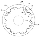
図3は図2の回転機のロータの断面形状を示している。図において、シャフト50の鉄心60は、リング型焼結磁石10の内周に設けられた凹部20及び凸部30に概ね沿うような凸部62及び凹部63をその外周に形成している。リング型焼結磁石10と鉄心60の間の隙間には、磁石の固定用の接着材(図示せず)が充填される。なお、当該隙間は0.03〜0.2mm程度である。また、鉄心60は電磁鋼板等を所定形状に打ち抜いて積層したものである。
FIG. 3 shows a cross-sectional shape of the rotor of the rotating machine of FIG. In the figure, the
図4は図2及び図3に示すロータを組み込んだ回転機を示す模式図である。図に示すように、ロータ100の外周には、巻線を施したステータ110が配置される。本実施の形態では、ステータ110は12スロットである。ロータ100は軸受120を介して回転機のケース130に回転可能に支持されている。
FIG. 4 is a schematic view showing a rotating machine incorporating the rotor shown in FIGS. 2 and 3. As shown in the figure, a
次に、本実施の形態のリング型焼結磁石の磁石厚さについて説明する。リング型焼結磁石の磁石厚さは、その最大厚さに対して最小厚さが小さいほど、起磁力分布を正弦波に近づける形状を実現しやすくなる。しかし、リング型焼結磁石の機械的な強度が弱くなり、磁石の製造中などに破損してしまうため、機械強度を維持する上で最小厚さが必要となる。本実施の形態のリング型焼結磁石の場合、最小磁石厚さは1mmである。磁石の強度を保つためには、最小厚さは最大厚さの30%以上が必要である。最小厚さが最大厚さの90%以上となると磁石の強度は十分得られるが、起磁力の高調波歪を低減する上で効果が少なくなってしまう。なお、磁石厚さ3mm、軸長30mmクラスのリング型焼結磁石では最小厚さは0.9mm以上が必要である。 Next, the magnet thickness of the ring-type sintered magnet of the present embodiment will be described. As for the magnet thickness of the ring-type sintered magnet, the smaller the minimum thickness with respect to the maximum thickness, the easier it is to realize a shape that approximates the magnetomotive force distribution to a sine wave. However, the mechanical strength of the ring-type sintered magnet is weakened and is damaged during the manufacture of the magnet, so that a minimum thickness is required to maintain the mechanical strength. In the case of the ring-type sintered magnet of the present embodiment, the minimum magnet thickness is 1 mm. In order to maintain the strength of the magnet, the minimum thickness needs to be 30% or more of the maximum thickness. When the minimum thickness is 90% or more of the maximum thickness, sufficient strength of the magnet can be obtained, but the effect is reduced in reducing harmonic distortion of magnetomotive force. In addition, the minimum thickness of a ring-type sintered magnet having a magnet thickness of 3 mm and an axial length of 30 mm is required to be 0.9 mm or more.
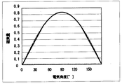
図5は本実施の形態のリング型焼結磁石の磁石厚さ分布を示す図である。図5は磁極1極分(電気角度が0度から180度)の磁石厚さ分布を示し、最大磁石厚さを基準とした(磁石厚さ)/(最大磁石厚さ)の分布を表している。本実施の形態では、図5の磁石厚さ分布をリング周方向に8極分繰り返し、電気角が48°以下の領域と132°以上の領域では、磁石の機械的強度を維持するため磁石厚さは略一定(上述した最小厚さ以上)としている。図6は比較例1としてリング型焼結磁石の外周に凹部及び凸部を設けた磁石厚さの分布を示している。図5と同様に磁石の機械的強度を維持するため磁石厚さが一定の領域を設けている。 FIG. 5 is a diagram showing the magnet thickness distribution of the ring-type sintered magnet of the present embodiment. FIG. 5 shows the magnet thickness distribution for one magnetic pole (electrical angle is 0 to 180 degrees), and represents the distribution of (magnet thickness) / (maximum magnet thickness) based on the maximum magnet thickness. Yes. In the present embodiment, the magnet thickness distribution of FIG. 5 is repeated for 8 poles in the ring circumferential direction, and the magnet thickness is maintained in the region where the electrical angle is 48 ° or less and the region where the electrical angle is 132 ° or more in order to maintain the mechanical strength of the magnet. The thickness is substantially constant (more than the above-mentioned minimum thickness). FIG. 6 shows a distribution of magnet thickness in which concave and convex portions are provided on the outer periphery of a ring-type sintered magnet as Comparative Example 1. Similar to FIG. 5, a region having a constant magnet thickness is provided to maintain the mechanical strength of the magnet.
ここで、リング型焼結磁石が発生する磁束量の回転方向の分布について説明する。図7は本実施の形態のリング型焼結磁石の磁束量を説明するための図である。図7において、リング型焼結磁石の中心をOとし、凹部20の周方向略中間位置を基準(θ=0度)とする回転角度をθとする。そして、角度θにおける磁束量(磁束密度)をΦ(θ)、磁石の起磁力をVm(θ)、鉄心60とステータ110間のギャップ長g(θ)とする。このとき、起磁力Vm(θ)は、磁石の単位長さあたりの起磁力vm(磁石の磁気特性で決まり一定)と磁石厚さLm(θ)で決まり、下記(1)式となる。
Here, the distribution in the rotation direction of the amount of magnetic flux generated by the ring-type sintered magnet will be described. FIG. 7 is a view for explaining the amount of magnetic flux of the ring-type sintered magnet of the present embodiment. In FIG. 7, the center of the ring-type sintered magnet is O, and the rotation angle with reference to the substantially intermediate position in the circumferential direction of the recess 20 (θ = 0 degrees) is θ. The amount of magnetic flux (magnetic flux density) at the angle θ is Φ (θ), the magnetomotive force of the magnet is Vm (θ), and the gap length g (θ) between the
Vm(θ)=vm・Lm(θ)・・・(1) Vm (θ) = vm · Lm (θ) (1)
従って、磁束量Φ(θ)は下記(2)式となる。 Therefore, the magnetic flux amount Φ (θ) is expressed by the following equation (2).
Φ(θ)=Vm(θ)/g(θ)=vm・Lm(θ)/g(θ)・・・(2) Φ (θ) = Vm (θ) / g (θ) = vm · Lm (θ) / g (θ) (2)
本実施の形態では、上述の磁束量分布Φ(θ)を正弦波分布に近似するように設定する。そうすると、本実施の形態のリング型焼結磁石の磁石の厚さLm(θ)は、磁石厚さの厚い領域(凸部30)において、次式(3)に従う。 In the present embodiment, the above-described magnetic flux amount distribution Φ (θ) is set so as to approximate a sine wave distribution. Then, the magnet thickness Lm (θ) of the ring-type sintered magnet of the present embodiment conforms to the following formula (3) in the thick magnet region (convex portion 30).
Lm(θ)≒a/(1/(k・sinθ)−1)・・・(3)
ここで a:磁石の最大厚さに対する磁石外周とステータ間のエアギャップの間隔
k:磁石厚さ最大の領域での、磁束量と起磁力の比例定数
k=Lm max・vm/((Lm max+a)/μ0)
Lm (θ) ≈a / (1 / (k · sin θ) −1) (3)
Where: a: gap of the air gap between the magnet outer circumference and the stator relative to the maximum magnet thickness
k: Proportional constant between the amount of magnetic flux and magnetomotive force in the maximum magnet thickness region
k = Lm max · vm / ((Lm max + a) / μ0)
これに対して、比較例1では、リング型焼結磁石の起磁力分布を正弦波分布に近づけることを目的として、磁石の厚さLm(θ)の分布を正弦波に近づけるように外周の凹部及び凸部を設定している。この場合、シャフトの鉄心とステータのギャップg(θ)は角度θによらず一定であるため、磁束量は磁石の厚さできまり、正弦波分布になる。磁石厚さの薄い領域では、磁路抵抗が大きく磁束が流れにくい。 On the other hand, in Comparative Example 1, for the purpose of bringing the magnetomotive force distribution of the ring-type sintered magnet closer to the sine wave distribution, the outer circumferential concave portion is made to bring the distribution of the magnet thickness Lm (θ) closer to the sine wave. And the convex part is set. In this case, since the gap g (θ) between the shaft core and the stator is constant regardless of the angle θ, the amount of magnetic flux is determined by the thickness of the magnet and has a sine wave distribution. In the thin magnet region, the magnetic path resistance is large and the magnetic flux does not flow easily.
一方、本実施の形態のリング型焼結磁石の場合は、磁石の厚さが薄い領域ではシャフトの鉄心60の外径が大きくなるため、鉄心60とステータ110のギャップが狭くなり、磁路抵抗が小さくなり、磁束が流れにくくなる現象が緩和される。
On the other hand, in the case of the ring-type sintered magnet according to the present embodiment, the outer diameter of the
図8は本実施の形態(図5の形状)のリング型焼結磁石の磁束量の分布を示す図である。図9は比較例1(図6の形状)のリング型焼結磁石の磁束量の分布を示す図である。なお、図8及び図9は磁極1極分(電気角度が0度から180度)の磁束量分布を示している。図5(本実施の形態)のリング型焼結磁石の形状と図6(比較例1)のリング型焼結磁石の形状を比較すると分かるように、図5(本実施の形態)のリング型焼結磁石の方が図6(比較例)のリング型焼結磁石よりも、平均的に磁石の厚さが薄くなり磁石の量が少なくなっているが、図8に示すように、リング型焼結磁石の凸部30の周方向中央部付近で正弦波状の分布が得られていることがわかる。
FIG. 8 is a diagram showing the distribution of the magnetic flux amount of the ring-type sintered magnet of the present embodiment (the shape of FIG. 5). FIG. 9 is a diagram showing the distribution of the magnetic flux amount of the ring-type sintered magnet of Comparative Example 1 (shape of FIG. 6). 8 and 9 show the magnetic flux amount distribution for one magnetic pole (electrical angle is 0 to 180 degrees). As can be seen by comparing the shape of the ring-type sintered magnet of FIG. 5 (this embodiment) with the shape of the ring-type sintered magnet of FIG. 6 (Comparative Example 1), the ring type of FIG. 5 (this embodiment). The sintered magnet is thinner than the ring-type sintered magnet of FIG. 6 (comparative example) on average, and the amount of magnet is smaller. However, as shown in FIG. It can be seen that a sinusoidal distribution is obtained near the center in the circumferential direction of the
なお、磁石厚さの厚い凸部30の領域において、リング内周を上記(3)式の曲線に近似するように形成したが、磁極中心位置が磁石の最大厚さ位置に来るようにリング内周を凸状の曲線形状にしても略同様の効果を得ることができる。
In the region of the
図5及び図6で示したリング型焼結磁石の磁石厚さの回転方向の積分値は磁石の使用量に比例する。この場合、図6のリング外周に凹部及び凸部を有するリング型焼結磁石に比較して、図5のリング内周に凹部及び凸部があるリング型焼結磁石では、磁石の使用量は25%少なくなる。なお、比較例2として、図6に示す磁石厚さの分布と同じ分布で、リング外周を円形状、内周に凹部及び凸部を設けた場合のリング型焼結磁石の磁束量の分布を図10に示す。この場合、磁路抵抗が少なくなる効果によって、正弦波からの歪は大きく、磁束量が増加している。 The integral value in the rotation direction of the magnet thickness of the ring-type sintered magnet shown in FIGS. 5 and 6 is proportional to the amount of magnet used. In this case, compared with the ring-type sintered magnet having the concave and convex portions on the outer periphery of the ring in FIG. 6, in the ring-type sintered magnet having the concave and convex portions on the inner periphery of the ring in FIG. 25% less. As Comparative Example 2, the distribution of the magnetic flux amount of the ring-type sintered magnet is the same as the distribution of the magnet thickness shown in FIG. 6, and the ring outer periphery has a circular shape and the inner periphery has recesses and projections. As shown in FIG. In this case, due to the effect of reducing the magnetic path resistance, the distortion from the sine wave is large and the amount of magnetic flux is increased.
次に、本実施の形態のリング型焼結磁石におけるスキュー着磁の方法と効果について説明する。図8の本実施の形態(図5の形状)のリング型焼結磁石の磁束量の分布において、磁石の厚さが一定の領域(凹部20の領域)である電気角度が45°以下、135°以上において、磁束量は一定となり、磁束量の分布における正弦波に対する高調波歪が大きくなる。そこで、図2に示すように、磁極(N極、S極)の境界が、磁石の厚さが薄くて一定の領域(凹部20の領域)にてリング軸方向に傾斜(スキュー)するように、スキュー着磁した。 Next, the method and effect of skew magnetization in the ring-type sintered magnet of the present embodiment will be described. In the distribution of the magnetic flux amount of the ring-type sintered magnet of the present embodiment (shape of FIG. 5) in FIG. 8, the electrical angle, which is the region where the magnet thickness is constant (region of the recess 20), is 45 ° or less, 135 Above 0 °, the amount of magnetic flux becomes constant, and the harmonic distortion with respect to the sine wave in the distribution of the amount of magnetic flux increases. Therefore, as shown in FIG. 2, the boundary between the magnetic poles (N pole and S pole) is inclined (skewed) in the ring axis direction in a certain area (the area of the recess 20) where the thickness of the magnet is thin. Skew magnetized.
このように、本実施の形態のリング型焼結磁石において、磁石の厚さが薄くて一定の領域(凹部20の領域)において、磁極の境界がリング軸方向に傾斜しているために、ステータ110に流れ込む磁束量を滑らかに変化させることができる。図11は上記のようにスキュー着磁した本実施の形態のリング型焼結磁石の磁束量の分布を示す図である。図に示すように、本例の磁束量の分布(図中の実線)において、正弦波分布(図中の点線)からのズレを非常に少なく抑えることができる。 As described above, in the ring-type sintered magnet of the present embodiment, since the boundary of the magnetic pole is inclined in the ring axis direction in the region where the magnet is thin and constant (the region of the recess 20), the stator The amount of magnetic flux flowing into 110 can be changed smoothly. FIG. 11 is a diagram showing the distribution of the magnetic flux amount of the ring-type sintered magnet according to the present embodiment skew-magnetized as described above. As shown in the figure, the deviation from the sine wave distribution (dotted line in the figure) can be suppressed very little in the magnetic flux amount distribution (solid line in the figure) of this example.
なお、磁極の境界がリング軸方向に対して傾斜するようにスキュー着磁させると、磁極の境界が傾斜している領域つまり磁石の厚さが一定の領域(凹部20の領域)において、異極の磁極同士が互いに磁束量をキャンセルさせあうため、磁石の発生する磁束量を有効に使用することには反する。しかしながら、本実施の形態の場合、磁石の厚さが薄い領域のみで磁極の境界が傾斜しているので、磁束量のキャンセルは少なく、影響が少ない。 When skew magnetization is performed so that the boundary of the magnetic pole is inclined with respect to the ring axis direction, in the region where the boundary of the magnetic pole is inclined, that is, the region where the magnet thickness is constant (the region of the recess 20), Since the magnetic poles of each other cancel each other, the amount of magnetic flux generated by the magnet is contrary to effective use. However, in the case of the present embodiment, since the boundary of the magnetic pole is inclined only in the region where the thickness of the magnet is thin, the cancellation of the magnetic flux amount is small and the influence is small.
スキュー着磁は通常、5次高調波を打ち消すような電気角72°前後のスキュー(傾斜)角が用いられることが多いが、本実施の形態の場合は、磁石の厚さの薄い一定の領域(凹部20の領域)に相当する角度でスキュー着磁させるのが好ましい。すなわち、本実施の形態の場合、電気角約90度でスキュー着磁している。 Skew magnetization usually uses a skew (inclination) angle of about 72 ° so as to cancel the fifth harmonic, but in the case of this embodiment, a constant region where the magnet is thin. It is preferable to skew-magnetize at an angle corresponding to (the region of the recess 20). That is, in the present embodiment, skew magnetization is performed at an electrical angle of about 90 degrees.
次に、本実施の形態のリング型焼結磁石の製造工程について説明する。本磁石の製造工程は、原料合金鋳造工程、粉砕工程、磁場中成形工程、焼結・熱処理工程、加工工程から構成される。具体的に説明すると、磁石の組成は、例えばNd:30wt%、B:1wt%、Dy:3wt%、Fe:残りwt%である。原料合金鋳造工程において高周波溶解で混合した原料合金を、水素脆性化処理、ジェットミルにより粉砕して(粉砕工程)、平均粒径4μmの磁性粉末を得る。その磁性粉末に磁場を加えて磁性結晶の方向を揃える配向を行い、内周に凹凸を有するリング形状に圧縮成形してリング成形体を製作する(磁場中成形工程)。そして、上記リング成形体を真空中で1080℃、900℃、600℃の焼結・熱処理工程を経て、リング焼結体を得る。なお、磁場中成形工程においては、磁場を加えながら加圧しても、磁場を加えた後、加圧してもよい。 Next, the manufacturing process of the ring-type sintered magnet of this embodiment will be described. The manufacturing process of the magnet includes a raw material alloy casting process, a pulverizing process, a forming process in a magnetic field, a sintering / heat treatment process, and a processing process. Specifically, the composition of the magnet is, for example, Nd: 30 wt%, B: 1 wt%, Dy: 3 wt%, and Fe: remaining wt%. The raw material alloy mixed by high frequency melting in the raw material alloy casting step is pulverized by hydrogen embrittlement treatment and a jet mill (pulverization step) to obtain a magnetic powder having an average particle size of 4 μm. A magnetic field is applied to the magnetic powder so as to align the direction of the magnetic crystal, and a ring molded body is manufactured by compression molding into a ring shape having irregularities on the inner periphery (molding process in a magnetic field). Then, the ring molded body is subjected to sintering and heat treatment processes at 1080 ° C., 900 ° C., and 600 ° C. in vacuum to obtain a ring sintered body. In the forming step in a magnetic field, pressurization may be performed while applying a magnetic field, or pressurization after applying a magnetic field.
磁場中成形工程におけるリング成形体において、磁石厚さが薄いところでも1mmあるため割れや欠けが生じにくい。焼結工程の焼結収縮のときも、同様の理由から焼結収縮時に形状歪が生じにくい。そのため磁石の割れ欠け変形が少なくなる。 In the ring molded body in the molding process in a magnetic field, cracks and chips are hardly generated because the magnet thickness is 1 mm even when the magnet thickness is thin. In the case of sintering shrinkage in the sintering process, shape distortion hardly occurs at the time of sintering shrinkage for the same reason. As a result, cracking and cracking deformation of the magnet is reduced.
上述の磁場中成形工程と焼結工程について詳細に説明する。金型として、内周が円形のダイス、外周にリング型磁石の内周の凹凸部に応じた凹凸部を有するコア、ダイスとコアに嵌め合わすことができる上パンチと下パンチを使用する。これらの金型は本実施の形態の場合、高さ15mmの成形体を成形できるように金型のキャビティの高さを30mm、ダイス高さを40mmとした。この金型を用いてリング外周が円形で内周に凹凸部を有する高さ15mmのリング成形体を複数個(例えば3個)作る。そして、複数個(例えば3個)のリング成形体を高さ方向に積み重ね、焼結することで、焼結後の高さ35mmでリング外周が円形、リング内周に凹凸部を有する本実施の形態のリング型焼結磁石を製造できる。なお、磁石高さが低い場合などは、1個のリング成形体を焼結することでリング型焼結磁石を製造しても良い。 The above-described forming step in a magnetic field and the sintering step will be described in detail. A die having a circular inner periphery, a core having an uneven portion corresponding to the uneven portion of the inner periphery of the ring magnet on the outer periphery, and an upper punch and a lower punch that can be fitted to the die and the core are used as the mold. In the case of this embodiment, these molds have a mold cavity height of 30 mm and a die height of 40 mm so that a molded body having a height of 15 mm can be formed. Using this mold, a plurality of (for example, three) ring molded bodies with a height of 15 mm having a circular outer periphery and an uneven portion on the inner periphery are produced. Then, by stacking and sintering a plurality of (for example, three) ring molded bodies in the height direction, the ring outer periphery is circular at a height of 35 mm after sintering, and the ring inner periphery has an uneven portion. A ring-shaped sintered magnet having a shape can be manufactured. In addition, when a magnet height is low etc., you may manufacture a ring-type sintered magnet by sintering one ring molded object.
上記のような、磁場中成形工程と焼結工程を用いるため、リング外周が円形状で、リング内周に凹凸部を有する本実施の形態のリング型焼結磁石を、割れや欠け、変形が発生することなく安定して製造することができる。 Since the ring forming step and the sintering step in the magnetic field as described above are used, the ring-shaped sintered magnet of the present embodiment having a circular outer periphery and an uneven portion on the inner periphery of the ring is not cracked, chipped, or deformed. It can be manufactured stably without generating.
最後に、本実施の形態のリング型焼結磁石10を取付けたロータ100と、前述した12スロットのステータ110とを組み合せてモータを製作した。そして、コギングトルクを測定した結果、リング内周に凹凸形状のない磁石厚さ一定のリング型磁石を用いた場合に比べて、コギングトルクを1/2以下に低減することができた。また、本実施の形態のリング型焼結磁石10を用いたモータでは、比較例1のリング型焼結磁石を用いたモータに比べてコギングトルクを20%低減することができ、さらに、磁石の使用量も比較例1に比べ25%低減することができた。
Finally, a motor was manufactured by combining the
本実施の形態のリング型焼結磁石をモータに組み込んだ状態では、N極とS極の境界付近である領域は磁石の厚さが薄くてその部分に逆磁界が加わりやすく、一般的に磁石は減磁しやすくなると考えられるが、当該領域ではステータ110と鉄心60との間隔が狭くパーミアンスが高いため減磁しにくいといった特徴も得られた。ただし、リング型焼結磁石10の磁石厚さの薄い領域(凹部20)において鉄心60との間隔が大きいと本実施の形態の効果が上がらず、また減磁しやすいといった問題も生じる。そのため、リング型焼結磁石10と鉄心60の間の間隔は、磁石厚さの薄い領域(凹部20)の長さ寸法以下が良い。
In the state where the ring-type sintered magnet of this embodiment is incorporated in a motor, the area near the boundary between the N pole and the S pole is thin and the magnetic field is likely to be applied to the area. However, in this region, the distance between the
以上のように本実施の形態によれば、リング軸に垂直な断面において、リング外周は円形状に形成されるとともに、リング内周はその周方向に凹部20及び凸部30が周期的に形成され、リング周方向にN極及びS極の磁極が交互に形成されており、磁極の境界が磁石厚さの薄い凹部20の領域に形成されているので、磁石厚さの薄い凹部20の領域において、リング型焼結磁石10の内周部に配設される鉄心60と外周部に配置されるステータ110を近接させることができ、磁石厚さが薄い凹部20の領域でも磁束が流れやすく、磁石厚さの薄い領域の磁石厚さの厚い領域に対する磁束量の低下が少なくなる。そのため、磁石の総重量に対するトルク発生に有効な磁束量の割合を増加することができ、リング外周に凹凸部を有するリング型焼結磁石と略同じ性能を保持しつつ、磁石の使用量を削減することができる。
As described above, according to the present embodiment, in the cross section perpendicular to the ring axis, the outer periphery of the ring is formed in a circular shape, and the
また、磁石厚さの薄い凹部20の領域において磁石厚さを略一定としたので、当該領域における機械的な強度が弱くなくなり、製造時における磁石の割れや欠け、リング形状の歪みを無くすことができる。
Further, since the magnet thickness is made substantially constant in the region of the
また、磁石厚さの厚い凸部30の領域において、リング内周を凸状の曲線形状、特に上記(3)式の曲線に近似して形成し、磁極の中心が凸部の最大磁石厚さ部分に位置するようにしたので、磁石の磁束量分布を正弦波形状に近似することができる。
Further, in the region of the
さらに、磁石の厚さが薄い凹部20の領域において、磁極の境界がリング軸方向に傾斜して形成されているので、当該領域における磁束量の分布の正弦波分布からのズレを少なく抑えることができる。
Further, since the boundary of the magnetic pole is formed in the ring axis direction in the region of the
上記実施の形態では、磁石の組成としてNd、B、Fe、Dyの例を示したが、Co、Al、Cu、その他添加元素を加えてもよい。 In the said embodiment, although the example of Nd, B, Fe, and Dy was shown as a composition of a magnet, you may add Co, Al, Cu, and another additive element.
また、上記実施の形態では、外周に凹凸部を設けた鉄心60として、電磁鋼板等の積層した例を示したが、冷鍛により製造したものでもよい。また、粉状の磁性材料を圧縮成形した圧粉鉄心で構成してもよい。また、リング型焼結磁石10と鉄心60の固定は、接着材を用いなくてもよく、ねじ等で機械的に固定しても、ロー付け等の固定でも良い。
Moreover, although the example which laminated | stacked electromagnetic steel plates etc. was shown as the
さらに、上記実施の形態では、8極のリング型焼結磁石と12スロットのステータで説明をおこなったが、磁極数やスロット数に依存するものではなく、他の磁極数のリング型焼結磁石においても、同様の効果を得ることができる。 Furthermore, in the above embodiment, the description has been made with an 8-pole ring-type sintered magnet and a 12-slot stator, but this does not depend on the number of magnetic poles or the number of slots. The same effect can be obtained also in.
実施の形態2.
本実施の形態では、上記リング型焼結磁石10において、磁石厚さの厚い領域(凸部30)では鉄心60とのギャップを0.06mm以下にするとともに、磁石厚さの薄い領域(凹部20)では鉄心60とのギャップを0.1mm以上にする。リング型焼結磁石10と鉄心60との固定を行う際に相互の位置決めが必要であるが、リング型焼結磁石の内周の全領域で嵌め合わせを行おうとすると、リング型焼結磁石10の内周部と鉄心60の外周部に高精度の形状精度を確保する必要が生じる。
In the present embodiment, in the ring-
そこで、本実施の形態では、磁石厚さの薄い領域(凹部20)で鉄心60とのギャップを広く、磁石厚さの厚い領域(凸部30)で鉄心60とのギャップを狭くすることにより、磁束量の大きな領域(凸部30)では磁路抵抗を最小限に少なくすることができ、磁束量の小さな領域(凹部20)では磁路抵抗が多少大きくても磁束量の減少の影響を受けなくて済み、全体としては磁束量を有効に活用できる。
Therefore, in the present embodiment, by widening the gap with the
また、磁石の厚さが厚い領域(凸部30)は、製造工程中の、磁石の加工前の状態(焼結後の状態)でも形状精度が高いため、焼結工程後に実施する加工工程(研削工程等)を省略して使用した場合においても位置決め精度が確保される。すなわち、加工工程を省いても、精度の高いロータの組立が実現でき、ロータに振れ等が発生しないため、騒音や振動が少ない回転機が実現できる。 In addition, the region where the magnet is thick (projection 30) has a high shape accuracy even before the magnet is processed (the state after sintering) during the manufacturing process. Positioning accuracy is ensured even when the grinding process is omitted. That is, even if the machining process is omitted, the assembly of the rotor with high accuracy can be realized, and no vibration or the like occurs in the rotor, so that a rotating machine with less noise and vibration can be realized.
ここで、本実施の形態において製造工程上得られる特徴について述べる。前述したようにネオジム等の希土類系焼結磁石の製造工程は、原料合金鋳造工程、粉砕工程、磁場中成形工程、焼結・熱処理工程、加工工程を経る。ここで、磁場中成形工程において磁性粉末を金型に給粉時の成形密度のばらつきを少なくすることと、焼結工程における焼結収縮による焼結歪を少なくすることで、次の加工工程の省略が可能となる。本形状のリング型焼結磁石の場合、磁石厚さの厚い領域(凸部30)では、金型への磁性粉末の給粉が安定していることと、焼結時の収縮が安定であることから、組立時に必要な形状精度を確保することが可能であり、磁石厚さの薄い領域(凹部20)で形状精度の制限を緩くしておいても、加工工程を省略することができる。ただし、加工工程を実施しても本実施の形態の効果は発揮できる。当然、磁石厚さの厚い領域のみを加工してもよい。また、全領域を加工してもよい。 Here, characteristics obtained in the manufacturing process in the present embodiment will be described. As described above, the manufacturing process of a rare earth sintered magnet such as neodymium undergoes a raw material alloy casting process, a pulverization process, a forming process in a magnetic field, a sintering / heat treatment process, and a processing process. Here, in the molding process in the magnetic field, by reducing the variation in the molding density when the magnetic powder is fed to the mold, and by reducing the sintering strain due to the sintering shrinkage in the sintering process, Omission is possible. In the case of a ring-shaped sintered magnet of this shape, in a region where the magnet thickness is thick (convex portion 30), the supply of magnetic powder to the mold is stable and the shrinkage during sintering is stable. Therefore, it is possible to ensure the shape accuracy required at the time of assembly, and the processing step can be omitted even if the restriction on the shape accuracy is loosened in the thin magnet region (recess 20). However, the effects of the present embodiment can be exhibited even if the processing steps are performed. Of course, you may process only the area | region where magnet thickness is thick. Further, the entire area may be processed.
以上のように、本実施の形態のリング型焼結磁石の形状によれば、製造における加工工程を省略あるいは簡略化することができ、磁石製造におけるロスを少なくし、製造コストを低減することができる。 As described above, according to the shape of the ring-type sintered magnet of the present embodiment, the manufacturing process can be omitted or simplified, the loss in magnet manufacturing can be reduced, and the manufacturing cost can be reduced. it can.
実施の形態3.
図12はこの発明の実施の形態3のリング型焼結磁石を用いた回転機のロータを示す斜視図、図13は図12の回転機のロータの断面形状を示す図である。
Embodiment 3 FIG.
12 is a perspective view showing a rotor of a rotating machine using a ring-type sintered magnet according to Embodiment 3 of the present invention, and FIG. 13 is a view showing a cross-sectional shape of the rotor of the rotating machine of FIG.
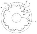
実施の形態1において、リング型焼結磁石10の内周部に配設される鉄心60は、リング型焼結磁石10の内周の凹部20及び凸部30に概ね沿うような凸部62及び凹部63をその外周に形成している。本実施の形態では、鉄心60の外周に、上記凸部62及び凹部63のほか、リング型焼結磁石10の磁石厚さが薄い凹部20に対向する位置に凹部64を設けている。
In the first embodiment, the
図12及び図13において、本実施の形態のリング型焼結磁石10は、実施の形態1と同様、リング外周が円形状に形成され、リング内周に凹部20及び凸部30が周期的に形成され、凹部20にあたる箇所では、磁石の厚さが一定となっている。また、その結晶方向を示す配向の方向は、略径方向を向いたラジアル配向である。
12 and 13, in the ring-
そして、リング型焼結磁石10は、シャフト50に固定された鉄心60の外周に取付けられる。また、リング型焼結磁石10には、リング周方向にN極及びS極の磁極が交互に形成されており、当該磁極の境界は磁石厚さが薄い領域である凹部20に形成されている。さらに、磁極の境界は、リング軸方向と略平行になるようにストレート着磁されている。
The ring-
また、鉄心60の外周には、リング型焼結磁石10の内周に設けられた凹部20及び凸部30に概ね沿うような凸部62及び凹部63が形成されている。さらに、鉄心60の外周には、上記凸部62及び凹部63のほか、リング型焼結磁石10の磁石厚さが薄い凹部20に対向する位置に凹部64が形成されている。本例では、凹部64は、凹部63と略同形状であり、リング型焼結磁石10の凸部30に概ね沿うような形状を成している。
Further, on the outer periphery of the
本実施の形態のリング型焼結磁石において、磁極は8極であり、鉄心60の凹部63,64は磁石の極数8極の倍である16個設けられている。また、磁石外径はΦ30mm、磁石の最大厚さは3mm、最小厚さは1mmである。さらに、磁石の軸長は35mmである。
In the ring-type sintered magnet according to the present embodiment, the magnetic pole has eight poles, and 16
本実施の形態では、リング型焼結磁石10の磁石の厚さが薄い領域(凹部20)において、鉄心60の外周に形成された凹部64と組み合わされる。そのため、磁石の薄い領域(凹部20)では鉄心60とステータ110との間隔が若干広くなり、磁路抵抗がその分大きくなる。そして、磁束量は、磁石の厚さが一定でも鉄心60とステータ110のギャップが広くなるためその分少なくなる。図14は本実施の形態のロータにおける磁束量の回転方向分布を示す図である。鉄心60の外周がリング型焼結磁石10の外周に沿った形状の場合(図8の磁束量分布)に比べ、正弦波の形状に近づき、高調波歪が少なくなることがわかる。
In the present embodiment, the ring-
本実施の形態の場合、同サイズの円筒型のリング型焼結磁石を使用した場合に比べてコギングトルクが1/2となり、磁石の使用量も25%低減できた。また、スキュー着磁のためのヨークが不要で、簡単なストレート着磁用ヨークを使用することによりリング型焼結磁石10の磁極が形成できる。
In the case of the present embodiment, the cogging torque is reduced by half compared to the case where a cylindrical ring-type sintered magnet of the same size is used, and the amount of magnet used can be reduced by 25%. Further, a yoke for skew magnetization is unnecessary, and the magnetic pole of the ring-
実施の形態4.
上記実施の形態では、リング型焼結磁石10の内周と鉄心60の外周のギャップを、磁極の境界に対して回転方向に対称になるように構成したが、リング型焼結磁石10の内周と鉄心60のギャップが軸方向に対して変化するように構成してもよい。
Embodiment 4 FIG.
In the above embodiment, the gap between the inner periphery of the ring-
図15及び図16はこの発明の実施の形態4のリング型焼結磁石を使用した回転機のロータの断面形状を示す図である。図15はリング軸方向の最下部における断面図であり、図16はリング軸方向の最上部における断面図である。 15 and 16 are views showing a cross-sectional shape of a rotor of a rotating machine using a ring-type sintered magnet according to Embodiment 4 of the present invention. FIG. 15 is a cross-sectional view in the lowermost part in the ring axis direction, and FIG. 16 is a cross-sectional view in the uppermost part in the ring axis direction.
図15及び図16において、リング型焼結磁石10は、実施の形態3と同様、リング外周が円形状に形成され、リング内周に凹部20及び凸部30が周期的に形成され、凹部20にあたる箇所では、磁石の厚さが一定となっている。また、その結晶方向を示す配向の方向は、略径方向を向いたラジアル配向である。
15 and 16, the ring-
また、リング型焼結磁石10には、リング周方向にN極及びS極の磁極が交互に形成されており、当該磁極の境界は磁石厚さが薄い領域である凹部20の略周方向中央位置に形成されており、リング軸方向と略平行になるようにストレート着磁されている。
The ring-
また、鉄心60の外周には、リング型焼結磁石10の内周の凹部20及び凸部30に概ね沿うような凸部62及び凹部63が形成されている。さらに、鉄心60の外周には、上記凸部62及び凹部63のほか、リング型焼結磁石10の磁石厚さが薄い凹部20に対向する位置に凹部64が形成されている。そして、本実施の形態では、上記凹部64は、そのリング周方向位置がリング軸方向において変化するように構成されている。すなわち、図15のリング軸方向下方においては、回転方向CCW方向のリング型焼結磁石10と鉄心60のギャップが広くなるように構成し、図16のようにリング軸方向上方に行くに従って、回転方向CCWと反対方向のリング型焼結磁石10と鉄心60のギャップが広くなるように構成する。
Further, on the outer periphery of the
以上のように、本実施の形態によれば、リング型焼結磁石10の磁極の境界がリング軸方向下部では回転方向CCWに位置し、リング軸方向上方になるに従い磁極の境界が回転方向と反対方向にシフトする。そのため、リング型焼結磁石の磁極の境界を所望の傾きでスキューすることができる。すなわち、本実施の形態の構成により、構成の簡単な着磁ヨークで実施できるストレート着磁でも、スキューの効果を得ることができ、コギングトルクやトルクリップルを低減することができる。
As described above, according to the present embodiment, the boundary of the magnetic pole of the ring-
実施の形態5.
上記実施の形態のリング型焼結磁石は、そのリング内周に、磁石厚さが一定の凹部と、凸状の曲線から成る凸部が形成されている。しかしながら、本発明では、リング内周の凹凸部は上記形状に限らず、本実施の形態に示すような種々の形状を採用することができる。
Embodiment 5. FIG.
In the ring-type sintered magnet of the above embodiment, a concave portion having a constant magnet thickness and a convex portion made of a convex curve are formed on the inner periphery of the ring. However, in the present invention, the uneven portion on the inner periphery of the ring is not limited to the above shape, and various shapes as shown in the present embodiment can be adopted.
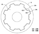
図17はこの発明の実施の形態5によるリング型焼結磁石の断面形状を示す図、図18は図17のリング型焼結磁石を取付けた回転機のロータの断面形状を示す図、図19は図17のリング型焼結磁石を取付けた回転機のロータを示す斜視図である。図において、本実施の形態のリング型焼結磁石10は、リング軸に垂直な断面において、リング外周が円形状に形成され、リング内周の周方向に磁石厚さが一定の凹部20Aと凸角形状の(折れ曲がり曲線で形成された)凸部30Aが周期的に形成されている。
17 is a diagram showing a cross-sectional shape of a ring-type sintered magnet according to Embodiment 5 of the present invention, FIG. 18 is a diagram showing a cross-sectional shape of a rotor of a rotating machine to which the ring-type sintered magnet of FIG. 17 is attached, FIG. FIG. 18 is a perspective view showing a rotor of a rotating machine to which the ring-type sintered magnet of FIG. 17 is attached. In the figure, the ring-
本実施の形態のリング型焼結磁石10は、ロータ100のシャフト50に固定された鉄心60の外周に取付けられる。図19に示すように、リング型焼結磁石10には、リング周方向にN極及びS極の磁極が交互に形成されており、当該磁極の境界は磁石厚さが薄い領域である凹部20Aに形成されている。さらに、磁極の境界は、リング軸方向に対して一定の傾斜角で傾くようにスキュー着磁されている。
Ring-
また、シャフト50の鉄心60は、リング型焼結磁石10の内周に設けられた凹部20A及び凸部30Aに概ね沿うような凸部62A及び凹部63Aをその外周に形成している。リング型焼結磁石10と鉄心60の間の隙間には、磁石の固定用の接着材(図示せず)が充填される。
Further, the
図20はこの発明の実施の形態5の他の例のリング型焼結磁石の断面形状を示す図である。上記実施の形態では、磁石厚さが薄い領域では磁石の厚さが一定の例を説明したが、磁石厚さが一定でなく変化がある形状であっても、トルクムラを低減する効果が損なわれることはない。すなわち、図20に示すように、リング型焼結磁石10のリング内周にS字曲線状の凸部30B及び凹部20Bを周期的に形成し、磁石厚さを円弧状に連続的に変化させるようにした。また、磁極の中心位置を凸部30Cの周方向の略中央位置に、磁極の境界を凹部20Cに配置する。図20のような形状にすることにより、磁石製造時におけるリング成形体への外力がリング形状の不連続部に集中することによるリング成形体の割れを防止することができ、また、焼結収縮時における不連続部への応力集中による割れ防止の効果が得られる。このように、図20の形状によれば、リング型焼結磁石10を安定して製造できる効果が得られるため、製造上のロスやコストを削減できる。
FIG. 20 is a diagram showing a cross-sectional shape of a ring-type sintered magnet according to another example of Embodiment 5 of the present invention. In the above-described embodiment, an example in which the magnet thickness is constant in the region where the magnet thickness is thin has been described. However, even if the magnet thickness is not constant but has a change shape, the effect of reducing torque unevenness is impaired. There is nothing. That is, as shown in FIG. 20, S-curved
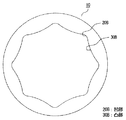
図21はこの発明の実施の形態5の他の例のリング型焼結磁石の断面形状を示す図である。図21のリング型焼結磁石10は、リング内周に2次曲線状の凸部30C及び凹部20Cを周期的に形成し、磁石の厚さが薄い領域(凹部20C)において磁石の厚さが均一な領域がない例である。本例において、磁極の中心位置を凸部30Cの周方向の略中央位置に、磁極の境界を凹部20Cに配置することにより、起磁力分布の高調波歪の低減は可能であり、また、鉄心60とステータ110間のギャップが磁石厚さの薄い領域(凹部20C)で狭くなるため、磁石の磁力を有効に活用でき磁石の使用量は少なくできる効果が得られる。本形状の場合、磁石の製造における磁場成形工程で使用する金型の形状が比較的簡単になる利点がある。
FIG. 21 is a diagram showing a cross-sectional shape of a ring-type sintered magnet according to another example of Embodiment 5 of the present invention. The ring-
図22は、図17、図20及び図21のリング型焼結磁石の回転方向の磁石厚さ分布を示す図である。また、図23は、図17、図20及び図21のリング型焼結磁石の回転方向の磁束密度分布を示す図である。なお、図22又は図23は、磁極1極分(電気角度が0度から180度)の磁石厚さ分布及び磁束密度分布を示し、それぞれ最大磁石厚さを基準とした(磁石厚さ)/(最大磁石厚さ)、(磁束密度)/(最大磁石厚さにおける磁束密度)の分布を表している。 FIG. 22 is a diagram showing the magnet thickness distribution in the rotation direction of the ring-type sintered magnets of FIGS. 17, 20, and 21. FIG. 23 is a diagram showing the magnetic flux density distribution in the rotational direction of the ring-type sintered magnets of FIGS. 17, 20, and 21. FIG. 22 or FIG. 23 shows the magnet thickness distribution and magnetic flux density distribution for one magnetic pole (electrical angle is 0 to 180 degrees), each based on the maximum magnet thickness (magnet thickness) / It shows the distribution of (maximum magnet thickness), (magnetic flux density) / (magnetic flux density at maximum magnet thickness).
図22において、図17のリング型焼結磁石の磁石の最大厚さtmaxと最小厚さtminの中間に当る半値(tmax+tmin)/2を定め、半値で決まる中心角(半値中心角と呼ぶ)の1極の磁極の中心角に対する割合である(半値中心角)/(磁極中心角)をパラメータとする。そして、図17のリング型焼結磁石の(半値中心角)/(磁極中心角)と、磁束密度分布の高調波の振幅、磁石の重量、(磁束密度分布の基本波振幅)/(磁石重量)の関係を図24、図25、図26に示す。 In FIG. 22, a half value (tmax + tmin) / 2 corresponding to the midpoint between the maximum thickness tmax and the minimum thickness tmin of the ring-type sintered magnet of FIG. 17 is determined, and the center angle determined by the half value (referred to as the half value center angle) A ratio of (half-value central angle) / (magnetic pole center angle), which is a ratio to the central angle of one magnetic pole, is a parameter. Then, the (half-value central angle) / (magnetic pole center angle) of the ring-type sintered magnet of FIG. 17, the harmonic amplitude of the magnetic flux density distribution, the weight of the magnet, (the fundamental wave amplitude of the magnetic flux density distribution) / (magnet weight). ) Are shown in FIG. 24, FIG. 25, and FIG.
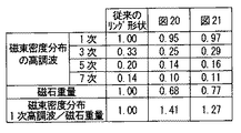
図24、図25、図26に示すように、リング型焼結磁石の半値中心角を小さくすることにより磁束密度分布の高調波は少なくなるが、それ以上に磁石重量が減少しており、そのため、磁束密度分布の基本波振幅/磁石重量は増加する。また、半値中心角が0.2〜0.8ではコギングトルク等のトルクムラの要因である磁束密度分布の5次、7次高調波が低減できることがわかる。また、図20及び図21のS字曲線状の凹凸部、二次曲線による凸部を有するリング型焼結磁石の(半値中心角)/(磁極中心角)はそれぞれ、0.56、0.7であり、図17の折れ曲がり直線形状のリング型焼結磁石の傾向とほぼ一致する。 As shown in FIGS. 24, 25, and 26, the harmonics of the magnetic flux density distribution are reduced by reducing the half-value central angle of the ring-type sintered magnet, but the magnet weight is further reduced. The fundamental wave amplitude / magnet weight of the magnetic flux density distribution increases. It can also be seen that when the half-value center angle is 0.2 to 0.8, the fifth and seventh harmonics of the magnetic flux density distribution, which is a cause of torque unevenness such as cogging torque, can be reduced. In addition, the (half-value central angle) / (magnetic pole central angle) of the ring-shaped sintered magnet having the S-shaped curved uneven portion and the convex portion formed by the quadratic curve in FIGS. 20 and 21 are 0.56,. 7, which almost coincides with the tendency of the bent linear sintered magnet in FIG.
次に、図27に、図20のS字曲線状リング型焼結磁石と、図21の二次曲線状のリング型焼結磁石と、磁石厚さが均一なリング型焼結磁石の比較を示す。比較する項目としては、磁束密度分布の基本波(1次)、3次、5次、7次高調波、磁石の重量、磁束密度分布の基本波振幅/磁石重量である。磁束密度分布の高調波は厚さが均一なリング型焼結磁石の基本波(1次)の振幅で規格化して示している。磁石重量は磁石厚さが均一なリング型磁石の重量で規格化して示す。図20のS次曲線状、図21の二次曲線状のリング型焼結磁石ともに、磁石重量が大幅に少なくなっているが基本波の減少幅は少なく、そのため、磁束密度分布の基本波振幅/磁石重量は大きくなっている。磁束密度分布の基本波はモータの回転に寄与する成分であり、磁石を有効に使えていることがわかる。一方、コギングトルクの発生要因となる磁束密度分布の高調波における5次、7次高調波はいずれも、従来のリング型磁石に比べて小さくなっており、トルクムラは小さくなる。 Next, FIG. 27 shows a comparison between the S-shaped curved ring-shaped sintered magnet of FIG. 20, the quadratic-curved ring-shaped sintered magnet of FIG. 21, and the ring-shaped sintered magnet having a uniform magnet thickness. Show. Items to be compared are the fundamental wave (primary) of the magnetic flux density distribution, the third, fifth, and seventh harmonics, the weight of the magnet, and the fundamental wave amplitude / magnet weight of the magnetic flux density distribution. The harmonics of the magnetic flux density distribution are shown normalized by the amplitude of the fundamental wave (primary) of a ring-type sintered magnet having a uniform thickness. The magnet weight is shown normalized by the weight of a ring magnet having a uniform magnet thickness. In both the S-shaped curved shape of FIG. 20 and the quadratic shaped ring-shaped sintered magnet of FIG. 21, the weight of the magnet is significantly reduced, but the amount of decrease in the fundamental wave is small. / The magnet weight is large. The fundamental wave of the magnetic flux density distribution is a component that contributes to the rotation of the motor, and it can be seen that the magnet can be used effectively. On the other hand, the fifth and seventh harmonics in the harmonics of the magnetic flux density distribution that are the cause of the cogging torque are both smaller than the conventional ring magnet, and the torque unevenness is reduced.
実施の形態6.
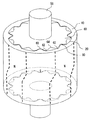
本実施の形態では、本発明の形状のリング型焼結磁石におけるスキュー着磁の変形例、つまりリング軸方向に対して磁極の境界をS字状にスキュー着磁する例について説明する。図28はこの発明の実施の形態6のリング型焼結磁石を取付けた回転機のロータを示す斜視図である。なお、図28は、実施の形態3(図12)の形状のリング型焼結磁石においてS字状にスキュー着磁を施した例を示している。すなわち、リング型焼結磁石10は、リング外周が円形状に形成され、リング内周に凹部20及び凸部30が周期的に形成され、凹部20にあたる箇所では磁石の厚さが一定となっている。
Embodiment 6 FIG.
In the present embodiment, a modified example of skew magnetization in the ring-shaped sintered magnet having the shape of the present invention, that is, an example in which the boundary of the magnetic pole is skewed in an S shape with respect to the ring axis direction will be described. FIG. 28 is a perspective view showing a rotor of a rotating machine to which a ring-type sintered magnet according to Embodiment 6 of the present invention is attached. FIG. 28 shows an example in which skew magnetization is applied in an S shape in the ring-type sintered magnet having the shape of the third embodiment (FIG. 12). That is, in the ring-
一方、リング型焼結磁石10の内周部に配設される鉄心60は、リング型焼結磁石10の内周の凹部20及び凸部30に概ね沿うような凸部62及び凹部63をその外周に形成していると共に、リング型焼結磁石10の磁石厚さが薄い凹部20に対向する位置に凹部64を設けている。
On the other hand, the
そして、リング型焼結磁石10には、リング周方向にN極及びS極の磁極が交互に形成されており、当該磁極の境界は磁石厚さが薄い領域である凹部20に形成されている。さらに、磁極の境界が、リング軸方向の上段及び下段ではストレートに形成され、上段及び下段の中間であるリング軸方向の所定領域において一定の傾斜角で傾くように段スキュー着磁されている。
In the ring-
実施の形態3の形状のリング型焼結磁石により、コギングトルクは十分低減可能であるが、モータの工作精度等によりコギングが発生する場合がある。また、モータによってはさらに低いコギングトルク(0.5%以下)が要求される場合がある。 Although the cogging torque can be sufficiently reduced by the ring-type sintered magnet having the shape of the third embodiment, cogging may occur depending on the working accuracy of the motor. Further, depending on the motor, a lower cogging torque (0.5% or less) may be required.
その場合、コギングトルクの実測結果をもとに、磁極の境界がスキューされている領域の上段及び下段に当たる磁石のコギングトルクが互いに打ち消し合うようにスキュー(傾斜)角度を設定すればよい。例えば、磁極の極数が8、スロット数12の場合、24周期の半分(機械角度15°/2で7.5°)にすることが有効となる。 In that case, based on the actual measurement result of the cogging torque, the skew (tilt) angle may be set so that the cogging torques of the magnets hitting the upper and lower stages of the region where the magnetic pole boundary is skewed cancel each other. For example, when the number of poles of the magnetic pole is 8 and the number of slots is 12, it is effective to set the half of 24 periods (a mechanical angle of 15 ° / 2 and 7.5 °).
なお、上記実施の形態では、段スキュー着磁した例を示したが、一般のいわゆるS字状にスキュー着磁しても良い。 In the above embodiment, an example in which step skew magnetization is performed has been described, but skew magnetization may be performed in a general so-called S shape.
なお、本実施の形態のS字状のスキュー着磁は、図12の形状のリング型焼結磁石に限らず、図2のリング型焼結磁石の形状等に適用するなどしても、同様の効果が得られる。 Note that the S-shaped skew magnetization of the present embodiment is not limited to the ring-shaped sintered magnet having the shape shown in FIG. The effect is obtained.
10 リング型焼結磁石、20,20A,20B,20C 凹部、
30,30A,30B,30C 凸部、50 シャフト、60 鉄心、
62,62A 凸部、63,63A 凹部、64 凹部、100 ロータ、
110 ステータ。
10 ring-type sintered magnet, 20, 20A, 20B, 20C recess,
30, 30A, 30B, 30C Convex part, 50 shaft, 60 iron core,
62, 62A convex part, 63, 63A concave part, 64 concave part, 100 rotor,
110 Stator.
Claims (14)
リング周方向にN極及びS極の磁極が交互に形成されており、上記磁極の境界が磁石厚さの薄い上記凹部の領域に形成されていることを特徴とするリング型焼結磁石。 In the cross section perpendicular to the ring axis, the outer periphery of the ring is formed in a circular shape, and the inner periphery of the ring is periodically formed with recesses and protrusions in the circumferential direction,
A ring-type sintered magnet, wherein magnetic poles of N poles and S poles are alternately formed in a circumferential direction of the ring, and a boundary between the magnetic poles is formed in the region of the concave portion having a thin magnet thickness.
Lm(θ)≒a/(1/(k・sinθ)−1)
ここで、Lm(θ):リング型焼結磁石の中心をOとし、凹部20の周方向略中心位 置(0度)を基準とした回転角度θにおける磁石厚さ
a:磁石の最大厚さに対する磁石外周とステータ間のエアギャップの間隔
k:磁石厚さ最大の領域での、磁束量と起磁力の比例定数
k=Lm max・vm/((Lm max+a)/μ0)
μ0:透磁率 The ring-type sintered magnet according to claim 3, wherein the magnet thickness conforms to Lm (θ) of the following formula in the region of the convex portion where the magnet is thick.
Lm (θ) ≈a / (1 / (k · sin θ) −1)
Here, Lm (θ): The thickness of the magnet at a rotation angle θ with the center of the ring-type sintered magnet being O and the substantially central position (0 degree) in the circumferential direction of the recess 20 as a reference.
a: Spacing of the air gap between the outer circumference of the magnet and the stator with respect to the maximum thickness of the magnet
k: Proportional constant between the amount of magnetic flux and magnetomotive force in the maximum magnet thickness region
k = Lm max · vm / ((Lm max + a) / μ0)
μ0: Permeability
Priority Applications (1)
| Application Number | Priority Date | Filing Date | Title |
|---|---|---|---|
| JP2006271942A JP2008092702A (en) | 2006-10-03 | 2006-10-03 | Ring-type sintered magnet, rotor, and dynamo-electric machine |
Applications Claiming Priority (1)
| Application Number | Priority Date | Filing Date | Title |
|---|---|---|---|
| JP2006271942A JP2008092702A (en) | 2006-10-03 | 2006-10-03 | Ring-type sintered magnet, rotor, and dynamo-electric machine |
Publications (2)
| Publication Number | Publication Date |
|---|---|
| JP2008092702A true JP2008092702A (en) | 2008-04-17 |
| JP2008092702A5 JP2008092702A5 (en) | 2009-01-22 |
Family
ID=39376256
Family Applications (1)
| Application Number | Title | Priority Date | Filing Date |
|---|---|---|---|
| JP2006271942A Pending JP2008092702A (en) | 2006-10-03 | 2006-10-03 | Ring-type sintered magnet, rotor, and dynamo-electric machine |
Country Status (1)
| Country | Link |
|---|---|
| JP (1) | JP2008092702A (en) |
Cited By (5)
| Publication number | Priority date | Publication date | Assignee | Title |
|---|---|---|---|---|
| JP2012010571A (en) * | 2010-05-28 | 2012-01-12 | Nisca Corp | Magnet rotor for rotary electric machine, manufacturing method of the same, and inner rotor type motor |
| CN103368293A (en) * | 2012-03-26 | 2013-10-23 | 珠海格力电器股份有限公司 | Motor rotor structure and motor with same |
| CN103904851A (en) * | 2014-03-28 | 2014-07-02 | 湖北立锐机电有限公司 | Magnetic ring structure, shaft and permanent magnet synchronous motor with magnetic ring structure and shaft |
| DE102013206787A1 (en) * | 2013-04-16 | 2014-10-16 | Efficient Energy Gmbh | Rotor and method of manufacturing a rotor |
| CN108565993A (en) * | 2018-06-11 | 2018-09-21 | 成都银河磁体股份有限公司 | A kind of magnet |
Citations (7)
| Publication number | Priority date | Publication date | Assignee | Title |
|---|---|---|---|---|
| JPH0576147A (en) * | 1991-09-10 | 1993-03-26 | Fuji Elelctrochem Co Ltd | Rotor for motor |
| JPH07222385A (en) * | 1994-01-31 | 1995-08-18 | Fuji Electric Co Ltd | Reverse salient cylindrical magnet synchronous motor |
| JPH0956092A (en) * | 1995-08-10 | 1997-02-25 | Daido Steel Co Ltd | Permanent-magnet rotor |
| JPH11308795A (en) * | 1998-04-20 | 1999-11-05 | Mitsubishi Electric Corp | Permanent magnet type synchronous motor |
| JP2004248378A (en) * | 2003-02-12 | 2004-09-02 | Toyoda Mach Works Ltd | Ring magnet, rotating electric machine with this ring magnet, and rotor for rotating electric machine |
| WO2005008862A1 (en) * | 2003-07-22 | 2005-01-27 | Aichi Steel Corporation Ltd. | Thin hybrid magnetization type ring magnet, yoke-equipped thin hybrid magnetization type ring magnet, and brush-less motor |
| JP2006230099A (en) * | 2005-02-17 | 2006-08-31 | Mitsubishi Electric Corp | Ring magnet and apparatus and method for manufacturing ring magnet |
-
2006
- 2006-10-03 JP JP2006271942A patent/JP2008092702A/en active Pending
Patent Citations (7)
| Publication number | Priority date | Publication date | Assignee | Title |
|---|---|---|---|---|
| JPH0576147A (en) * | 1991-09-10 | 1993-03-26 | Fuji Elelctrochem Co Ltd | Rotor for motor |
| JPH07222385A (en) * | 1994-01-31 | 1995-08-18 | Fuji Electric Co Ltd | Reverse salient cylindrical magnet synchronous motor |
| JPH0956092A (en) * | 1995-08-10 | 1997-02-25 | Daido Steel Co Ltd | Permanent-magnet rotor |
| JPH11308795A (en) * | 1998-04-20 | 1999-11-05 | Mitsubishi Electric Corp | Permanent magnet type synchronous motor |
| JP2004248378A (en) * | 2003-02-12 | 2004-09-02 | Toyoda Mach Works Ltd | Ring magnet, rotating electric machine with this ring magnet, and rotor for rotating electric machine |
| WO2005008862A1 (en) * | 2003-07-22 | 2005-01-27 | Aichi Steel Corporation Ltd. | Thin hybrid magnetization type ring magnet, yoke-equipped thin hybrid magnetization type ring magnet, and brush-less motor |
| JP2006230099A (en) * | 2005-02-17 | 2006-08-31 | Mitsubishi Electric Corp | Ring magnet and apparatus and method for manufacturing ring magnet |
Cited By (6)
| Publication number | Priority date | Publication date | Assignee | Title |
|---|---|---|---|---|
| JP2012010571A (en) * | 2010-05-28 | 2012-01-12 | Nisca Corp | Magnet rotor for rotary electric machine, manufacturing method of the same, and inner rotor type motor |
| CN103368293A (en) * | 2012-03-26 | 2013-10-23 | 珠海格力电器股份有限公司 | Motor rotor structure and motor with same |
| DE102013206787A1 (en) * | 2013-04-16 | 2014-10-16 | Efficient Energy Gmbh | Rotor and method of manufacturing a rotor |
| US10256686B2 (en) | 2013-04-16 | 2019-04-09 | Efficient Energy Gmbh | Rotor and method for producing a rotor |
| CN103904851A (en) * | 2014-03-28 | 2014-07-02 | 湖北立锐机电有限公司 | Magnetic ring structure, shaft and permanent magnet synchronous motor with magnetic ring structure and shaft |
| CN108565993A (en) * | 2018-06-11 | 2018-09-21 | 成都银河磁体股份有限公司 | A kind of magnet |
Similar Documents
| Publication | Publication Date | Title |
|---|---|---|
| JP7173119B2 (en) | permanent magnet piece | |
| US7618496B2 (en) | Radial anisotropic sintered magnet and its production method, magnet rotor using sintered magnet, and motor using magnet rotor | |
| JP5860654B2 (en) | Inner rotor type permanent magnet motor | |
| US20140062254A1 (en) | Permanent Magnet Rotating Electrical Machine | |
| US9716411B2 (en) | Permanent-magnet-type rotating electric mechanism | |
| JP2008245488A (en) | Ring-like magnet, manufacturing method therefor, and motor | |
| JP2008141853A (en) | Biaxial concentric motor | |
| JP4391964B2 (en) | Ring magnet and method for manufacturing ring magnet | |
| WO2010116921A1 (en) | Magnetic circuit structure | |
| JP2008092702A (en) | Ring-type sintered magnet, rotor, and dynamo-electric machine | |
| JP2012095401A (en) | Rotor of rotary electric machine and rotary electric machine | |
| JP2008167615A (en) | Single-phase claw pole permanent magnet motor | |
| JP2020103039A (en) | Axial air gap type electric motor | |
| JP4644875B2 (en) | End plates used for motors and rotors of motors | |
| JP5325074B2 (en) | Rotating electric machine and its stator | |
| JP6384543B2 (en) | Polar anisotropic ring magnet and rotor using the same | |
| JP2008109725A (en) | Ring-type sintered magnet, production process therefor and permanent magnet motor | |
| JP2007336624A (en) | Multi-phase claw tooth type permanent magnet motor | |
| JP6403672B2 (en) | Rotating electric machine and elevator hoisting machine | |
| JP2006254622A (en) | Permanent magnet type motor | |
| JP4694253B2 (en) | Permanent magnet rotating electric machine | |
| JP3943532B2 (en) | Sintered ring magnet | |
| JP2011147288A (en) | Rotor of synchronous motor | |
| JP6987327B1 (en) | Core piece, stator core, stator, and rotary electric machine | |
| JP2017147920A (en) | Surface magnet rotator |
Legal Events
| Date | Code | Title | Description |
|---|---|---|---|
| A521 | Written amendment |
Free format text: JAPANESE INTERMEDIATE CODE: A523 Effective date: 20081201 |
|
| A621 | Written request for application examination |
Free format text: JAPANESE INTERMEDIATE CODE: A621 Effective date: 20081201 |
|
| A977 | Report on retrieval |
Free format text: JAPANESE INTERMEDIATE CODE: A971007 Effective date: 20110512 |
|
| A131 | Notification of reasons for refusal |
Free format text: JAPANESE INTERMEDIATE CODE: A131 Effective date: 20110607 |
|
| A521 | Written amendment |
Free format text: JAPANESE INTERMEDIATE CODE: A523 Effective date: 20110801 |
|
| A131 | Notification of reasons for refusal |
Free format text: JAPANESE INTERMEDIATE CODE: A131 Effective date: 20120626 |
|
| A02 | Decision of refusal |
Free format text: JAPANESE INTERMEDIATE CODE: A02 Effective date: 20121106 |