JP2008091320A - Lamp fastener for semiconductor processing reactor - Google Patents
Lamp fastener for semiconductor processing reactor Download PDFInfo
- Publication number
- JP2008091320A JP2008091320A JP2007159858A JP2007159858A JP2008091320A JP 2008091320 A JP2008091320 A JP 2008091320A JP 2007159858 A JP2007159858 A JP 2007159858A JP 2007159858 A JP2007159858 A JP 2007159858A JP 2008091320 A JP2008091320 A JP 2008091320A
- Authority
- JP
- Japan
- Prior art keywords
- eyelet
- screw
- lamp
- fastener
- assembly
- Prior art date
- Legal status (The legal status is an assumption and is not a legal conclusion. Google has not performed a legal analysis and makes no representation as to the accuracy of the status listed.)
- Granted
Links
- 239000004065 semiconductor Substances 0.000 title claims abstract description 13
- 239000004020 conductor Substances 0.000 claims abstract 2
- 238000000034 method Methods 0.000 claims description 17
- 238000005229 chemical vapour deposition Methods 0.000 claims description 10
- 238000010438 heat treatment Methods 0.000 description 12
- 230000007246 mechanism Effects 0.000 description 4
- 229910001369 Brass Inorganic materials 0.000 description 3
- 239000010951 brass Substances 0.000 description 3
- 238000006243 chemical reaction Methods 0.000 description 3
- 239000010453 quartz Substances 0.000 description 3
- 239000002994 raw material Substances 0.000 description 3
- VYPSYNLAJGMNEJ-UHFFFAOYSA-N silicon dioxide Inorganic materials O=[Si]=O VYPSYNLAJGMNEJ-UHFFFAOYSA-N 0.000 description 3
- XUIMIQQOPSSXEZ-UHFFFAOYSA-N Silicon Chemical compound [Si] XUIMIQQOPSSXEZ-UHFFFAOYSA-N 0.000 description 2
- 238000012986 modification Methods 0.000 description 2
- 230000004048 modification Effects 0.000 description 2
- 229910052710 silicon Inorganic materials 0.000 description 2
- 239000010703 silicon Substances 0.000 description 2
- 239000000758 substrate Substances 0.000 description 2
- 239000010409 thin film Substances 0.000 description 2
- 241000233805 Phoenix Species 0.000 description 1
- 238000000137 annealing Methods 0.000 description 1
- 238000005530 etching Methods 0.000 description 1
- 239000010408 film Substances 0.000 description 1
- 230000006698 induction Effects 0.000 description 1
- 239000000463 material Substances 0.000 description 1
- 239000002184 metal Substances 0.000 description 1
- 230000002093 peripheral effect Effects 0.000 description 1
Images


Classifications
-
- H—ELECTRICITY
- H01—ELECTRIC ELEMENTS
- H01R—ELECTRICALLY-CONDUCTIVE CONNECTIONS; STRUCTURAL ASSOCIATIONS OF A PLURALITY OF MUTUALLY-INSULATED ELECTRICAL CONNECTING ELEMENTS; COUPLING DEVICES; CURRENT COLLECTORS
- H01R11/00—Individual connecting elements providing two or more spaced connecting locations for conductive members which are, or may be, thereby interconnected, e.g. end pieces for wires or cables supported by the wire or cable and having means for facilitating electrical connection to some other wire, terminal, or conductive member, blocks of binding posts
- H01R11/11—End pieces or tapping pieces for wires, supported by the wire and for facilitating electrical connection to some other wire, terminal or conductive member
- H01R11/26—End pieces terminating in a screw clamp, screw or nut
-
- C—CHEMISTRY; METALLURGY
- C23—COATING METALLIC MATERIAL; COATING MATERIAL WITH METALLIC MATERIAL; CHEMICAL SURFACE TREATMENT; DIFFUSION TREATMENT OF METALLIC MATERIAL; COATING BY VACUUM EVAPORATION, BY SPUTTERING, BY ION IMPLANTATION OR BY CHEMICAL VAPOUR DEPOSITION, IN GENERAL; INHIBITING CORROSION OF METALLIC MATERIAL OR INCRUSTATION IN GENERAL
- C23C—COATING METALLIC MATERIAL; COATING MATERIAL WITH METALLIC MATERIAL; SURFACE TREATMENT OF METALLIC MATERIAL BY DIFFUSION INTO THE SURFACE, BY CHEMICAL CONVERSION OR SUBSTITUTION; COATING BY VACUUM EVAPORATION, BY SPUTTERING, BY ION IMPLANTATION OR BY CHEMICAL VAPOUR DEPOSITION, IN GENERAL
- C23C16/00—Chemical coating by decomposition of gaseous compounds, without leaving reaction products of surface material in the coating, i.e. chemical vapour deposition [CVD] processes
- C23C16/44—Chemical coating by decomposition of gaseous compounds, without leaving reaction products of surface material in the coating, i.e. chemical vapour deposition [CVD] processes characterised by the method of coating
- C23C16/48—Chemical coating by decomposition of gaseous compounds, without leaving reaction products of surface material in the coating, i.e. chemical vapour deposition [CVD] processes characterised by the method of coating by irradiation, e.g. photolysis, radiolysis, particle radiation
- C23C16/481—Chemical coating by decomposition of gaseous compounds, without leaving reaction products of surface material in the coating, i.e. chemical vapour deposition [CVD] processes characterised by the method of coating by irradiation, e.g. photolysis, radiolysis, particle radiation by radiant heating of the substrate
-
- H—ELECTRICITY
- H01—ELECTRIC ELEMENTS
- H01L—SEMICONDUCTOR DEVICES NOT COVERED BY CLASS H10
- H01L21/00—Processes or apparatus adapted for the manufacture or treatment of semiconductor or solid state devices or of parts thereof
- H01L21/67—Apparatus specially adapted for handling semiconductor or electric solid state devices during manufacture or treatment thereof; Apparatus specially adapted for handling wafers during manufacture or treatment of semiconductor or electric solid state devices or components ; Apparatus not specifically provided for elsewhere
- H01L21/67005—Apparatus not specifically provided for elsewhere
- H01L21/67011—Apparatus for manufacture or treatment
- H01L21/67098—Apparatus for thermal treatment
- H01L21/67115—Apparatus for thermal treatment mainly by radiation
-
- H—ELECTRICITY
- H05—ELECTRIC TECHNIQUES NOT OTHERWISE PROVIDED FOR
- H05B—ELECTRIC HEATING; ELECTRIC LIGHT SOURCES NOT OTHERWISE PROVIDED FOR; CIRCUIT ARRANGEMENTS FOR ELECTRIC LIGHT SOURCES, IN GENERAL
- H05B3/00—Ohmic-resistance heating
- H05B3/0033—Heating devices using lamps
- H05B3/0038—Heating devices using lamps for industrial applications
- H05B3/0047—Heating devices using lamps for industrial applications for semiconductor manufacture
-
- F—MECHANICAL ENGINEERING; LIGHTING; HEATING; WEAPONS; BLASTING
- F16—ENGINEERING ELEMENTS AND UNITS; GENERAL MEASURES FOR PRODUCING AND MAINTAINING EFFECTIVE FUNCTIONING OF MACHINES OR INSTALLATIONS; THERMAL INSULATION IN GENERAL
- F16B—DEVICES FOR FASTENING OR SECURING CONSTRUCTIONAL ELEMENTS OR MACHINE PARTS TOGETHER, e.g. NAILS, BOLTS, CIRCLIPS, CLAMPS, CLIPS OR WEDGES; JOINTS OR JOINTING
- F16B41/00—Measures against loss of bolts, nuts, or pins; Measures against unauthorised operation of bolts, nuts or pins
- F16B41/002—Measures against loss of bolts, nuts or pins
-
- F—MECHANICAL ENGINEERING; LIGHTING; HEATING; WEAPONS; BLASTING
- F16—ENGINEERING ELEMENTS AND UNITS; GENERAL MEASURES FOR PRODUCING AND MAINTAINING EFFECTIVE FUNCTIONING OF MACHINES OR INSTALLATIONS; THERMAL INSULATION IN GENERAL
- F16B—DEVICES FOR FASTENING OR SECURING CONSTRUCTIONAL ELEMENTS OR MACHINE PARTS TOGETHER, e.g. NAILS, BOLTS, CIRCLIPS, CLAMPS, CLIPS OR WEDGES; JOINTS OR JOINTING
- F16B43/00—Washers or equivalent devices; Other devices for supporting bolt-heads or nuts
-
- H—ELECTRICITY
- H01—ELECTRIC ELEMENTS
- H01R—ELECTRICALLY-CONDUCTIVE CONNECTIONS; STRUCTURAL ASSOCIATIONS OF A PLURALITY OF MUTUALLY-INSULATED ELECTRICAL CONNECTING ELEMENTS; COUPLING DEVICES; CURRENT COLLECTORS
- H01R11/00—Individual connecting elements providing two or more spaced connecting locations for conductive members which are, or may be, thereby interconnected, e.g. end pieces for wires or cables supported by the wire or cable and having means for facilitating electrical connection to some other wire, terminal, or conductive member, blocks of binding posts
- H01R11/11—End pieces or tapping pieces for wires, supported by the wire and for facilitating electrical connection to some other wire, terminal or conductive member
- H01R11/12—End pieces terminating in an eye, hook, or fork
-
- H—ELECTRICITY
- H01—ELECTRIC ELEMENTS
- H01R—ELECTRICALLY-CONDUCTIVE CONNECTIONS; STRUCTURAL ASSOCIATIONS OF A PLURALITY OF MUTUALLY-INSULATED ELECTRICAL CONNECTING ELEMENTS; COUPLING DEVICES; CURRENT COLLECTORS
- H01R4/00—Electrically-conductive connections between two or more conductive members in direct contact, i.e. touching one another; Means for effecting or maintaining such contact; Electrically-conductive connections having two or more spaced connecting locations for conductors and using contact members penetrating insulation
- H01R4/28—Clamped connections, spring connections
- H01R4/30—Clamped connections, spring connections utilising a screw or nut clamping member
- H01R4/302—Clamped connections, spring connections utilising a screw or nut clamping member having means for preventing loosening of screw or nut, e.g. vibration-proof connection
Abstract
Description
本発明は、概ね、半導体加工リアクタに適切な加熱ランプに関する。 The present invention relates generally to heating lamps suitable for semiconductor processing reactors.
化学気相成長(CVD)は、半導体産業において非常によく知られている、シリコンウエハなどの基板上に原料から薄膜を形成するプロセスである。CVDプロセスでは、堆積される原料成分を含む気体分子が、ウエハに供給されて、化学反応によりウエハ上にその原料から薄膜が形成される。一般に、CVDプロセスは、化学反応を促進し高品質の膜を生成するように、高温で行われる。 Chemical vapor deposition (CVD) is a process well known in the semiconductor industry for forming a thin film from a raw material on a substrate such as a silicon wafer. In the CVD process, gas molecules containing raw material components to be deposited are supplied to the wafer, and a thin film is formed from the raw material on the wafer by a chemical reaction. In general, CVD processes are performed at high temperatures to promote chemical reactions and produce high quality films.
基板(例えば、シリコンウエハ)は、抵抗加熱、誘導加熱、または放射加熱を用いて加熱し得る。これらの間では、放射加熱が、最も効率のよい技術であり、よって、いくつかのタイプのCVDに、特にコールドウォール型リアクタに、現在好ましい方法であり、このリアクタでは、各加熱サイクルにおいて急速加熱することが望ましい。同様に、放射加熱は、短時間アニール(RTA)、高速熱処理装置(RTP)、エッチング器具などの多数の他のタイプの半導体加工リアクタにおいて好ましい。放射加熱には、リアクタと呼ばれる高温炉内に赤外線ランプを配置する必要がある。現在、ランプは、真鍮座金およびねじでリアクタに留め付けられる。リアクタ内の空間は制限されるので、これらのねじは、差し込みおよび/または交換が難しく、またリアクタの機器自体の中で紛失してしまうことも多い。紛失したねじは、リアクタに損傷を与え、電気的短絡を引き起こす恐れがあり、その結果、ランプの交換中にねじの場所を突き止め交換する時間が、無駄になる。 The substrate (eg, a silicon wafer) can be heated using resistance heating, induction heating, or radiant heating. Among these, radiant heating is the most efficient technique and is therefore the currently preferred method for some types of CVD, especially for cold wall reactors, where rapid heating is used in each heating cycle. It is desirable to do. Similarly, radiant heating is preferred in many other types of semiconductor processing reactors such as short time annealing (RTA), rapid thermal processing equipment (RTP), etching tools and the like. For radiant heating, it is necessary to place an infrared lamp in a high-temperature furnace called a reactor. Currently, lamps are fastened to the reactor with brass washers and screws. Due to the limited space in the reactor, these screws are difficult to insert and / or replace and are often lost in the reactor equipment itself. Lost screws can damage the reactor and cause an electrical short, resulting in wasted time to locate and replace the screw during lamp replacement.
したがって、先の構成の上述の問題を回避する、半導体加工リアクタ内において加熱ランプを留め付ける手段への要望が存在する。 Accordingly, there is a need for a means for fastening a heating lamp in a semiconductor processing reactor that avoids the above-described problems of previous configurations.
本発明の一態様において、半導体加工用ランプを提供する。ランプは、ランプボディと、ランプボディ内のフィラメントと、被捕捉型の締結具アセンブリと、フィラメントから被捕捉型の締結具への電気的接続を提供する導電コネクタと、を含む。 In one aspect of the present invention, a semiconductor processing lamp is provided. The lamp includes a lamp body, a filament within the lamp body, a captured fastener assembly, and a conductive connector that provides an electrical connection from the filament to the captured fastener.
被捕捉型の締結具は、いくつかの形態の1つを取り得ることが理解される。好ましい実施形態では、被捕捉型の締結具は、ねじ切りされたハトメ形末端部を含む。ねじ切りされたねじをハトメ形末端部に螺合させる。ねじの軸の上部のねじ山は、一旦ねじ切りされた部分がねじ切りされたハトメを通過するとねじが自由に回転し得るように、取り除く。別の実施形態では、ハトメ内にねじを保持するように、ランプの導線をハトメの被加締め部分に通す。別の実施形態では、環状の溝を有するねじをハトメ形末端部に挿入する。続いて、保持用スナップリングを環状の溝に係合させる。さらに別の実施形態では、ハトメ形末端部にねじを挿入し、ハトメ形末端部の上部のタブをねじの頭部に係合させる。さらに別の実施形態では、ハウジングアセンブリを有するハトメ形末端部にねじを挿入し、アームにより末端部にヒンジ式に連結したハウジングアセンブリをねじの頭部上に折り曲げる。さらに別の実施形態では、円形の蟻溝を頭部の底に有するねじを、ハトメ形末端部に挿入する。ハトメ形末端部は、ノッチ付きの突起部を有し、ノッチ付き突起部は、円形の蟻溝と係合する上面から延びる。 It will be appreciated that the captured fastener may take one of several forms. In a preferred embodiment, the captured fastener includes a threaded end piece. Screw the threaded screw into the eyelet shaped end. The upper thread of the screw shaft is removed so that once the threaded portion passes the threaded eyelet, the screw can rotate freely. In another embodiment, the lamp leads are threaded through the crimped portion of the eyelet so as to retain the screw in the eyelet. In another embodiment, a screw having an annular groove is inserted into the eyelet shaped end. Subsequently, the holding snap ring is engaged with the annular groove. In yet another embodiment, a screw is inserted into the eyelet end and the tab at the top of the eyelet end engages the head of the screw. In yet another embodiment, a screw is inserted into the eyelet-shaped end having a housing assembly, and the housing assembly hinged to the end by an arm is folded over the head of the screw. In yet another embodiment, a screw having a circular dovetail at the bottom of the head is inserted into the grommet end. The eyelet-shaped end portion has a notched protrusion, and the notched protrusion extends from the upper surface that engages the circular dovetail.
本発明の別の態様に係る、半導体加工リアクタ用ランプのハトメ形末端部内にねじを維持するための方法を提供する。本方法は、頭部と長い軸部分とを備えるねじを設けるステップを、含み、当該ステップでは、長い軸部分は、ねじ切りされた部分を有する。ねじをハトメ形末端部内に挿入する。ハトメ形末端部からねじが外れないように、ねじをハトメ形末端部内に捕捉する。 In accordance with another aspect of the present invention, a method for maintaining a screw in a grommet end of a semiconductor processing reactor lamp is provided. The method includes providing a screw comprising a head and a long shaft portion, wherein the long shaft portion has a threaded portion. Insert the screw into the grommet end. The screw is captured within the eyelet end so that the screw does not come off the eyelet end.
本発明の別の態様に係る化学気相成長リアクタを提供する。リアクタは、ランプと、ランプをリアクタ内に留めるための締結具と、ランプをリアクタから取り外した後、締結具をランプ上に保持するための手段と、を含む。 A chemical vapor deposition reactor according to another aspect of the present invention is provided. The reactor includes a lamp, a fastener for retaining the lamp in the reactor, and means for holding the fastener on the lamp after the lamp is removed from the reactor.
これらは、本発明の他の態様であって、以下の説明および添付の図面から容易に理解されるだろう。当該図面では、同様の番号は、同様の部品を指し、これは、本発明を示すためであって、本発明を限定する意図はない。 These are other aspects of the present invention and will be readily understood from the following description and accompanying drawings. In the drawings, like numerals refer to like parts and are intended to illustrate the present invention and are not intended to limit the present invention.
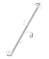
図1に、リアクタ内にあるのが一般的である先行技術のランプ10を示す。ここに示すランプ10は、一般に、2つのハトメ形末端部12を含み、このハトメ形末端部は、導電金属からなり、管14の両側に配置され、当該管14は、一般に、石英または他の透過性材料からなる。フィラメント16は、管14の中を通り、各ハトメ形末端部12に電気的に接続される。各ハトメ形末端部12は、(図ではプラスの)真鍮ねじ18および座金20でリアクタに留め付けられる。よって、電源が末端部12に接続されると、一般に当業者に知られるように、フィラメント16には、電流が流れ、放射エネルギー源となり得る。困ったことに、リアクタ内の空間は制限されているので、ねじ18および座金20の取り外しおよび回収を行いにくい。これらのランプはその作動で消耗するので、新しいランプと交換する必要が頻繁に生じる。このように絶えず交換を行うことによって、締結具が落下し紛失する可能性が高くなる。その上、一般的なリアクタは、20を超えるランプ(ハトメおよび締結具は40)を収容するので、締結具が落下する可能性は高くなる。
FIG. 1 shows a
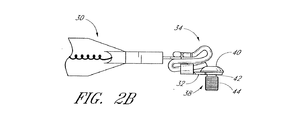
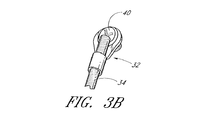
この問題への1つの解決方法として、ハトメ形末端部で締結具を捕捉することを提案する。図2Aおよび図3Aの好ましい実施形態に示すように、石英ランプ30をワイヤまたは導電コネクタ34によりハトメ形末端部32に取り付ける。ハトメ形末端部32の開口部36の内側は、ねじ切りされている。この好ましい実施形態では、六角形の受け部をボタン状頭部40に設けた結果、締結具またはねじ38は、アレンレンチで締め付けられる。当然ながら、代替駆動機構も使用できるので、どんなタイプのねじまたはボルトと取り替えてよい。長い軸部分が、ボタン状頭部40から延びる。軸は、アンダーカット状でねじ切りされていない円筒形中間部42と、先端が鈍い、ねじ切りされた端部44とを有する。捕捉型ねじの組み立ては、ねじ切りされたハトメの中にねじ38を螺合させることにより行う。組み立て後、ねじ切りされていない中間部42は、ハトメ36内を自由に回転するが、ねじ38は、故意に緩めなければ、ねじ切りされたハトメから外れることはない。ランプ30をリアクタ内に取り付ける際、ねじ切りされていない中間部42はハトメ36内において回転自在なままで、ねじ切りされた端部44をリアクタの電極に螺合させ得る。
One solution to this problem is to capture the fastener at the eyelet end. As shown in the preferred embodiment of FIGS. 2A and 3A, a
図1および図2A〜図15の実施形態に係るランプが使用される、例示的な半導体加工リアクタは、アリゾナ州フェニックスのASM America,Inc.から市販品を入手可能なEpsilon(登録商標)化学気相成長リアクタである。Epsilon(登録商標)のチャンバ用の加熱システムの一構成の説明が、「Heating System for Reaction Chamber of Chemical Vapor Deposition Equipment」という発明の名称の、1990年12月4日発行の米国特許第4,975,561号明細書にあり、その開示は、参照によりここに組み込まれる。これに関連して、ここに記載のランプの容量は、6kWから10kWであることが好ましい。 An exemplary semiconductor processing reactor in which lamps according to the embodiments of FIGS. 1 and 2A-15 are used is ASM America, Inc. of Phoenix, Arizona. Epsilon® chemical vapor deposition reactor available commercially from A description of one configuration of a heating system for an Epsilon® chamber is given in US Pat. No. 4,975, issued Dec. 4, 1990, entitled “Heating System for Reaction Chamber of Chemical Vapor Deposition Equipment”. No. 561, the disclosure of which is hereby incorporated by reference. In this connection, the capacity of the lamp described here is preferably between 6 kW and 10 kW.
図2Bおよび図3Bに変更した実施形態を示し、当該実施形態では、導電コネクタ34は、延長された真鍮の導線を含み、当該導線は、ねじ38をハトメ形末端部32と接触させて下方に偏ったままにしておくことを支援する。導電コネクタ34は、ハトメ形末端部32の保持部を通って延ばされ、次に、加締められて、その結果、延ばされた部分が、ねじ38の頭部40と接触しそれを保持することを助ける。ここに示すように、この実施形態のハトメ形末端部32には、内側にねじ溝を具える必要はない。
A modified embodiment is shown in FIGS. 2B and 3B, in which the
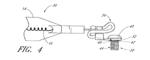
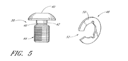
図4および図5に、本発明の別の実施形態に係る、被捕捉型の締結具アセンブリを示す。締結具またはねじ38は、ボタン状頭部40と、頭部40から延びる長い軸部とを有する。軸は、アンダーカット状でねじ切りされていない円筒形中間部42と、先端が鈍くねじ切りされた端部44と、を有する。環状の溝46(図5)が、ねじ切りされた端部44に最も近い端部に隣接して設けられる。ねじ部材を、ハトメとの関係において捕捉されて回転し得るように保持するための保持用スナップリング48(例えば、Eリング、Cリング)が設けられる。保持用スナップリング48は、間隙52を有する環状の周縁リム50を含む。リム50は、ねじ部材の環状の溝46と係合し得る。被捕捉型のねじの組み立ては、座金を伴ってまたは伴わずに、ハトメ形末端部32の中にねじ38を挿入することにより行う。ねじ部材は、保持用スナップリング48のリム50をねじ38の環状の溝46内に係合させることにより、捕捉され、リング48は、ハトメ形末端部32の下側に配置される。
4 and 5 illustrate a captured fastener assembly according to another embodiment of the present invention. The fastener or screw 38 has a button-
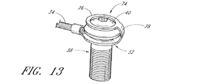
図6は、本発明のさらに別の実施形態に係る被捕捉型の締結具アセンブリの側面図であり、図7は、本発明のさらに別の実施形態に係る被捕捉型の締結具アセンブリの平面図である。石英ランプ30は、導電コネクタ34によりハトメ形末端部32に取り付けられる。締結具またはねじ38は、六角形の受け部付きのボタン状頭部40と、先端が鈍くねじ切りされた部分44とを有する。ハトメ形末端部32はねじ切りされていないので、ねじ38に、ねじ切りされていない部分を含ませる必要はない。ねじ38を、ハトメ末端部32との関係において捕捉されて回転し得るように保持するために、ハトメ32は、上向きに突出する四角形の3つのタブ60を上面の直径の周りに均等な間隔をおいて配置した統合型の捕捉部分を有する。ここに示した3つの撓み得るタブの代わりに、1つまたはそれ以上の撓み得るタブを使用してよい。図8〜図9に示すように、被捕捉型のねじの組み立ては、ハトメ形末端部32の中に、座金を伴ってまたは伴わずに、ねじ38を挿入することにより行う。ねじ38の頭部40上にタブ60が撓むことにより、ねじ38が捕捉される。図10に示すように、ここに示す撓み得るタブの構成の代わりに、タブを、適合性のある形状にして、例えば、タブ60が、係合すると、ねじ部材の頭部40の周りにスナップ留めされ得る波状にして固定し得ることが、理解されるだろう。
FIG. 6 is a side view of a captured fastener assembly according to still another embodiment of the present invention, and FIG. 7 is a plan view of the captured fastener assembly according to still another embodiment of the present invention. FIG. The
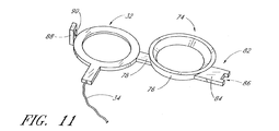
図11は、本発明のさらに別の実施形態に係る被捕捉型の締結具アセンブリの側面図であり、図12は、本発明のさらに別の実施形態に係る被捕捉型の締結具アセンブリの上下面の図である。ねじを、ハトメ形末端部32との関係において捕捉され回転し得るように保持するために、ハウジングアセンブリ74を追加することにより、ハトメ形末端部32を変更している。ハウジングアセンブリ74は、円錐形のキャップ部材76を含み、当該キャップ部材76は、アーム78によりハトメ形末端部32にヒンジ式に連結される。アーム部78は、ハトメ部分にハウジングアセンブリをかぶせるように適合されて、ねじ部材の頭部40に係合させて捕捉することを目的として、半径周りに屈曲させ得る。ねじ部材の頭部にドライバーを到達させるための貫通孔80を、キャップの上部に設ける。締め付け機構(図示せず)をねじに到達させ締め付け機構でねじを操作し得る程度大きく、ハトメ形末端部32からねじが外れるのを妨げる程度小さい、締め付け機構の大きさを選択し得るように、孔80の直径を選択する。
FIG. 11 is a side view of a captured fastener assembly according to still another embodiment of the present invention, and FIG. 12 is a top view of the captured fastener assembly according to still another embodiment of the present invention. It is a figure of a lower surface. The
本例では、キャッチアセンブリ82が、円錐形のキャップ76の部材に設けられて、キャップを係合させると固定されるが、図13に示した代替案のように、キャッチアセンブリは省略してよい。図11および図12に戻ると、キャッチアセンブリ82は、固定型の長方形のタブ84を含み、当該タブ84は、円錐形のキャップ部材76の側から外側に延び、遠位端にノッチ86を有する。キャッチアセンブリ82は、タブ88をさらに備え、当該タブ88は、ハトメ形末端部32から上向きに延び適合性のあるキャッチ90を有する。図14に示すように、キャッチ90が円錐形のハウジングアセンブリ74に直接係合するように、ここに示すノッチ86は省略してよいことに留意する。
In this example, a
被捕捉型のねじは、ねじ38を、またはねじおよび座金をハトメ形末端部32の中に挿入することにより、組み立てられる。ねじ部材は、円錐形のキャップ部材76をねじの頭部上に折り曲げることにより、捕捉される。キャッチアセンブリ82を使用する場合、円錐形のキャップ76のノッチ付きのタブ84は、ハトメ形末端部32の適合性のあるタブ90内に係合する。他の構成では、ここに示す円錐形のキャップの構成の代わりに、キャップを他の外形、例えば、リング形にし得ることが理解されるだろう。
The captured screw is assembled by inserting the
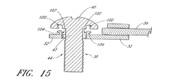
図15は、本発明のさらに別の実施形態における被捕捉型の締結具アセンブリの側面図である。締結具またはねじ38は、六角形の受け部付きのボタン状頭部40を有し、長い軸部分が、頭部40から延びる。軸は、アンダーカット状のねじ切りされていない円筒形の中間部42と、先端が鈍いねじ切りされた端部44とを有する。軸の周りに同心に形成された円形の蟻溝100は、ねじ頭部40の底面に設けられた凹所である。円形の蟻溝100の内径は、ハトメ形末端部32の直径より小さいが、軸の主な直径よりも大きいことに留意する。ハトメ形末端部は、上面から上向きに延び概ね円筒形のカラー102を有する。カラーの内径は、ハトメ形末端部32の内径と位置を合わせる。カラー102は、上面から外側に延び適合性のあるノッチ104を有する。被捕捉型のねじは、ねじ38をハトメ形末端部32の中に挿入することにより、組み立てられる。ねじ部材38は、ねじ部材の円形の蟻溝100を、カラー延長部102の適合性のあるノッチ104に係合させることにより、捕捉される。他の構成において、ここに示したノッチ付きカラーの代わりに、適合性のあるノッチ付きの係合部材を、ハトメ形末端部の上面から上向きに延びる2つまたはそれ以上のノッチ付きのタブなどの他の構成にし得ることが、理解されるだろう。
FIG. 15 is a side view of a captured fastener assembly in yet another embodiment of the present invention. The fastener or screw 38 has a button-
前述の各実施形態では、意図的な変更をしなければねじがハトメから垂直方向に持ち上がらず、ねじが外れないという意味で、ねじが、ハトメ形末端部内に捕捉される。しかしながら、放射加熱された半導体リアクタ内において対応の端子または電極に迅速に取り付けるためのねじは、ハトメ内を自由に回転する。 In each of the foregoing embodiments, the screw is captured in the eyelet shaped end in the sense that unless it is deliberately changed, the screw will not lift vertically from the eyelet and will not come off. However, screws for rapid attachment to corresponding terminals or electrodes in a radiantly heated semiconductor reactor rotate freely in the eyelet.
本発明の範囲を逸脱せずに種々の変更および変形を行い得ることを、当業者は理解するだろう。このような変更および変形は、添付の特許請求の範囲に定める本発明の範囲内であるものとする。 Those skilled in the art will appreciate that various changes and modifications can be made without departing from the scope of the invention. Such modifications and variations are intended to be within the scope of the invention as defined in the appended claims.
Claims (25)
前記ランプボディ内のフィラメントと、
被捕捉型の締結具アセンブリと、
導電コネクタと、
を備え、
前記フィラメントから前記被捕捉型の締結具アセンブリへの電気的接続を提供する半導体加工用ランプアセンブリ。 A lamp body,
A filament in the lamp body;
A captured fastener assembly;
A conductive connector;
With
A semiconductor processing lamp assembly that provides an electrical connection from the filament to the captured fastener assembly.
頭部と、ねじ切りされた部分を有する長い軸部分とを含むねじを設けるステップと、
前記ねじを前記ハトメ形末端部内に挿入するステップと、
前記ハトメ形末端部から前記ねじが外れないように、前記ねじを前記ハトメ形末端部内に捕捉するステップと、
を含む方法。 A method of maintaining a screw in a grommet end of a semiconductor processing reactor lamp, the method comprising:
Providing a screw comprising a head and a long shaft portion having a threaded portion;
Inserting the screw into the eyelet end;
Capturing the screw within the eyelet-shaped end so that the screw is not removed from the eyelet-shaped end;
Including methods.
前記ねじ切りされた端部の近位端に隣接して環状の溝を設けるステップと、
前記ねじを前記ハトメ形末端部の開口部に挿入するステップと、
保持用リングを前記環状の溝内にスナップ留めするステップと、
を含む請求項17に記載の方法。 The capturing step includes
Providing an annular groove adjacent the proximal end of the threaded end;
Inserting the screw into the eyelet-shaped end opening;
Snapping a retaining ring into the annular groove;
The method of claim 17 comprising:
前記ハトメ形末端部の上面から上向きに突出する複数のタブを設けるステップと、
前記ねじを前記ハトメ形末端部の開口部に挿入するステップと、
前記タブを前記ねじの頭部上に配置するステップと、
を含む請求項17に記載の方法。 The capturing step includes
Providing a plurality of tabs projecting upward from the upper surface of the eyelet-shaped end portion;
Inserting the screw into the eyelet-shaped end opening;
Placing the tab on the head of the screw;
The method of claim 17 comprising:
アームを含むハウジングアセンブリを設けるステップであって、前記アームは、前記ハトメ形末端部から延び、前記ハトメ形末端部から間隔をおいて配置されたハウジング部を有し、前記ハウジング部は、開口部を含み、前記アーム部分は、前記ハトメ形末端部上に前記ハウジング部を配置するように適合されて半径周りに撓ませることができる、ステップと、
前記ねじを前記ハトメ形末端部の開口部に挿入するステップと、
前記ハウジングアセンブリを前記ねじの頭部上に配置するステップと、
を含む請求項17に記載の方法。 The capturing step includes
Providing a housing assembly including an arm, the arm having a housing portion extending from and spaced from the eyelet-shaped end portion, the housing portion having an opening portion; The arm portion is adapted to position the housing portion on the eyelet-shaped end and can be bent about a radius; and
Inserting the screw into the eyelet-shaped end opening;
Placing the housing assembly on a head of the screw;
The method of claim 17 comprising:
前記ハウジング部の遠位の、前記ハトメ形末端部の側から延び、キャッチ用突起部を受け入れるように適合されたキャッチタブを設けるステップと、
前記ハウジングアセンブリが前記ねじの頭部上に配置されたとき、前記ノッチ付きタブを前記キャッチタブ内に係合させるステップと、
をさらに含む請求項22に記載の方法。 Providing the housing assembly with a notched tab extending distally of the eyelet-shaped end;
Providing a catch tab extending from a side of the eyelet shaped distal end of the housing portion and adapted to receive a catch projection;
Engaging the notched tab within the catch tab when the housing assembly is disposed on a head of the screw;
The method of claim 22 further comprising:
前記頭部の底面に円形の蟻溝を設けるステップと、
前記ハトメ形末端部の上面から上向きに延びる1つまたはそれ以上のノッチ付き突起部を設けるステップと、
前記ねじを前記ハトメ形末端部の開口部に挿入するステップと、
前記ノッチ付き突起部を前記円形の蟻溝内に係合させるステップと、
を含む請求項17に記載の方法。 The capturing step includes
Providing a circular dovetail on the bottom of the head;
Providing one or more notched protrusions extending upward from the top surface of the eyelet-shaped end;
Inserting the screw into the eyelet-shaped end opening;
Engaging the notched protrusion in the circular dovetail;
The method of claim 17 comprising:
化学気相成長リアクタ内にランプを留めるための締結具と、
前記ランプを前記リアクタから取り外した後、前記ランプ上に前記締結具を保持するための手段と、
を含む化学気相成長リアクタ。 A lamp,
A fastener for fastening the lamp in the chemical vapor deposition reactor;
Means for holding the fastener on the lamp after removing the lamp from the reactor;
A chemical vapor deposition reactor comprising:
Applications Claiming Priority (2)
| Application Number | Priority Date | Filing Date | Title |
|---|---|---|---|
| US11/502,935 | 2006-08-11 | ||
| US11/502,935 US7597574B2 (en) | 2006-08-11 | 2006-08-11 | Lamp fasteners for semiconductor processing reactors |
Publications (3)
| Publication Number | Publication Date |
|---|---|
| JP2008091320A true JP2008091320A (en) | 2008-04-17 |
| JP2008091320A5 JP2008091320A5 (en) | 2010-08-05 |
| JP5301796B2 JP5301796B2 (en) | 2013-09-25 |
Family
ID=38581881
Family Applications (1)
| Application Number | Title | Priority Date | Filing Date |
|---|---|---|---|
| JP2007159858A Active JP5301796B2 (en) | 2006-08-11 | 2007-06-18 | Chemical vapor deposition reactor |
Country Status (3)
| Country | Link |
|---|---|
| US (1) | US7597574B2 (en) |
| EP (1) | EP1893001A3 (en) |
| JP (1) | JP5301796B2 (en) |
Cited By (2)
| Publication number | Priority date | Publication date | Assignee | Title |
|---|---|---|---|---|
| JP2019525409A (en) * | 2016-07-22 | 2019-09-05 | サン−ゴバン グラス フランス | Glazing with conductive elements and its electrical connection |
| KR20220067438A (en) * | 2020-11-17 | 2022-05-24 | 주식회사 유라코퍼레이션 | Fixing Structure for Wire Bolt |
Families Citing this family (3)
| Publication number | Priority date | Publication date | Assignee | Title |
|---|---|---|---|---|
| DE102009034128A1 (en) * | 2009-07-20 | 2011-01-27 | Haver & Boecker Ohg | Protective device for a machine part |
| CN114651134A (en) * | 2019-11-07 | 2022-06-21 | 费森尤斯医疗护理德国有限责任公司 | Anti-drop component for screw, anti-drop screw assembly, anti-drop screw nut assembly and corresponding parts, combined structure and assembly |
| EP4298352A1 (en) * | 2021-02-26 | 2024-01-03 | RDI (Robaina Design Innovations) LLC | Fastener assembly |
Citations (7)
| Publication number | Priority date | Publication date | Assignee | Title |
|---|---|---|---|---|
| JPS54104987U (en) * | 1978-01-10 | 1979-07-24 | ||
| US4692343A (en) * | 1985-08-05 | 1987-09-08 | Spectrum Cvd, Inc. | Plasma enhanced CVD |
| JPS62201465U (en) * | 1986-06-12 | 1987-12-22 | ||
| JPH07100863B2 (en) * | 1987-06-18 | 1995-11-01 | アドヴァンスド・セミコンダクター・マテリアルズ・インコーポレーテッド | Heating device for reaction chamber of chemical vapor deposition equipment |
| FR2758910A1 (en) * | 1997-01-29 | 1998-07-31 | Peugeot | Earth terminal for use in vehicle electrical wiring system |
| JP2002289549A (en) * | 2001-03-28 | 2002-10-04 | Hitachi Kokusai Electric Inc | Wafer treatment device |
| JP2006164621A (en) * | 2004-12-03 | 2006-06-22 | Ushio Inc | Heater lamp |
Family Cites Families (27)
| Publication number | Priority date | Publication date | Assignee | Title |
|---|---|---|---|---|
| BE406408A (en) * | 1933-11-22 | |||
| US2151807A (en) | 1936-06-18 | 1939-03-28 | Benjamin Electric Ltd | Cable terminal |
| US2387055A (en) * | 1942-05-20 | 1945-10-16 | Gen Electric | Electric switch for discharge lamps |
| US2454243A (en) * | 1945-09-07 | 1948-11-16 | Arthur E Wiedenhoeft | Lighting fixture |
| BE465060A (en) * | 1946-05-23 | |||
| US2706804A (en) | 1952-09-27 | 1955-04-19 | Gilbert Co A C | Wire connection binding clip |
| US3376779A (en) * | 1965-10-23 | 1968-04-09 | Sol Jack | Self-locking pin |
| US3505636A (en) * | 1967-05-08 | 1970-04-07 | Clell D Mcdowell | Clamping bolt assembly for an easily loosened clamp |
| US3561075A (en) | 1969-07-15 | 1971-02-09 | Motorola Inc | Threaded fastener captivating device |
| US3862397A (en) * | 1972-03-24 | 1975-01-21 | Applied Materials Tech | Cool wall radiantly heated reactor |
| US4049335A (en) * | 1977-01-10 | 1977-09-20 | Julian Victor J | Sealed battery threaded stud termination |
| US4261402A (en) * | 1978-11-06 | 1981-04-14 | Textron, Inc. | Captive thread forming terminal screw |
| US4632497A (en) * | 1985-09-18 | 1986-12-30 | Allen-Bradley Company, Inc. | Terminal assembly for electrical apparatus |
| JPH04328043A (en) * | 1991-04-26 | 1992-11-17 | Nippon Sheet Glass Co Ltd | Mounting structure for vehicle marker lamp |
| US5372781A (en) * | 1992-02-18 | 1994-12-13 | Solarchem Enterprises Inc. | UV reactor assembly with improved lamp cooling means |
| US5533916A (en) | 1994-01-19 | 1996-07-09 | Leviton Manufacturing Co., Inc. | Reverse wire termination device |
| US5511301A (en) * | 1994-07-25 | 1996-04-30 | Textron Inc. | Self retaining fastener |
| DE9412215U1 (en) * | 1994-07-28 | 1994-09-22 | Lamson & Sessions Gmbh | Cable lug with fastening element |
| JP3725913B2 (en) * | 1995-04-12 | 2005-12-14 | 株式会社ソミック石川 | Ball joint device |
| US5781692A (en) * | 1997-06-04 | 1998-07-14 | Trw Inc. | Quartz lamp heater assembly for thin film deposition apparatus |
| JP3371359B2 (en) * | 1997-07-10 | 2003-01-27 | 矢崎総業株式会社 | Terminal connection fixing structure |
| DE60125428T2 (en) * | 2000-03-07 | 2007-10-04 | Sumitomo Wiring Systems, Ltd., Yokkaichi | Arrangement for preventing incorrect connection of battery terminals, battery and contact terminals |
| JP3659863B2 (en) | 2000-04-06 | 2005-06-15 | 大日本スクリーン製造株式会社 | Heat treatment equipment |
| US6280263B1 (en) * | 2000-05-02 | 2001-08-28 | Yazaki North America, Inc. | Anti-rotation terminal with captured nut |
| TW538974U (en) * | 2001-01-03 | 2003-06-21 | Mosel Vitelic Inc | Heating lamp brackets for reaction chambers of evaporation coating machines |
| US7075037B2 (en) | 2001-03-02 | 2006-07-11 | Tokyo Electron Limited | Heat treatment apparatus using a lamp for rapidly and uniformly heating a wafer |
| US6648692B1 (en) * | 2002-09-30 | 2003-11-18 | Rockwell Automation Technologies, Inc. | Zero space fuse system |
-
2006
- 2006-08-11 US US11/502,935 patent/US7597574B2/en active Active
-
2007
- 2007-06-18 JP JP2007159858A patent/JP5301796B2/en active Active
- 2007-08-09 EP EP07015663A patent/EP1893001A3/en not_active Withdrawn
Patent Citations (7)
| Publication number | Priority date | Publication date | Assignee | Title |
|---|---|---|---|---|
| JPS54104987U (en) * | 1978-01-10 | 1979-07-24 | ||
| US4692343A (en) * | 1985-08-05 | 1987-09-08 | Spectrum Cvd, Inc. | Plasma enhanced CVD |
| JPS62201465U (en) * | 1986-06-12 | 1987-12-22 | ||
| JPH07100863B2 (en) * | 1987-06-18 | 1995-11-01 | アドヴァンスド・セミコンダクター・マテリアルズ・インコーポレーテッド | Heating device for reaction chamber of chemical vapor deposition equipment |
| FR2758910A1 (en) * | 1997-01-29 | 1998-07-31 | Peugeot | Earth terminal for use in vehicle electrical wiring system |
| JP2002289549A (en) * | 2001-03-28 | 2002-10-04 | Hitachi Kokusai Electric Inc | Wafer treatment device |
| JP2006164621A (en) * | 2004-12-03 | 2006-06-22 | Ushio Inc | Heater lamp |
Cited By (9)
| Publication number | Priority date | Publication date | Assignee | Title |
|---|---|---|---|---|
| JP2019525409A (en) * | 2016-07-22 | 2019-09-05 | サン−ゴバン グラス フランス | Glazing with conductive elements and its electrical connection |
| KR20220067438A (en) * | 2020-11-17 | 2022-05-24 | 주식회사 유라코퍼레이션 | Fixing Structure for Wire Bolt |
| KR20220166252A (en) * | 2020-11-17 | 2022-12-16 | 주식회사 유라코퍼레이션 | Fixing Structure for Wire Bolt |
| KR20220166769A (en) * | 2020-11-17 | 2022-12-19 | 주식회사 유라코퍼레이션 | Fixing Structure for Wire Bolt |
| KR20220166768A (en) * | 2020-11-17 | 2022-12-19 | 주식회사 유라코퍼레이션 | Fixing Structure for Wire Bolt |
| KR102484079B1 (en) | 2020-11-17 | 2023-01-04 | 주식회사 유라코퍼레이션 | Fixing Structure for Wire Bolt |
| KR102484076B1 (en) * | 2020-11-17 | 2023-01-04 | 주식회사 유라코퍼레이션 | Fixing Structure for Wire Bolt |
| KR102484081B1 (en) | 2020-11-17 | 2023-01-04 | 주식회사 유라코퍼레이션 | Fixing Structure for Wire Bolt |
| KR102484080B1 (en) | 2020-11-17 | 2023-01-04 | 주식회사 유라코퍼레이션 | Fixing Structure for Wire Bolt |
Also Published As
| Publication number | Publication date |
|---|---|
| EP1893001A3 (en) | 2008-09-17 |
| JP5301796B2 (en) | 2013-09-25 |
| EP1893001A2 (en) | 2008-02-27 |
| US20080038950A1 (en) | 2008-02-14 |
| US7597574B2 (en) | 2009-10-06 |
Similar Documents
| Publication | Publication Date | Title |
|---|---|---|
| JP5301796B2 (en) | Chemical vapor deposition reactor | |
| KR102322400B1 (en) | High temperature electrode connections | |
| JP5650547B2 (en) | Cam lock electrode clamp | |
| JP3189241U (en) | Shower head electrode and gasket | |
| CN201781676U (en) | Inner electrode, with clamped and mechanically fastened edge, of spray nozzle electrode assembly | |
| US7699669B2 (en) | Screw assembly for electrical connectors | |
| KR20090068284A (en) | Components for a plasma processing apparatus | |
| JP2021510010A (en) | Lift pin system for wafer operation | |
| JP2006352114A (en) | Board support for clamping electric connector | |
| JP2006073531A (en) | High-temperature lamp connector for double-base type lamp and socket | |
| JP2007530894A (en) | Method and system for securing components used in plasma processing | |
| JP5015869B2 (en) | Modular gas ion source | |
| US6113704A (en) | Substrate-supporting device for semiconductor processing | |
| WO2011116990A1 (en) | Electrode arrangement | |
| JP2008091320A5 (en) | Chemical vapor deposition reactor | |
| TWI575825B (en) | Electronic device | |
| US8602802B2 (en) | Easy assembling one click bulb socket | |
| TW201447971A (en) | Discharge lamp and tool for attaching and detaching discharge lamp | |
| JP2007024212A (en) | Conductive fastener | |
| JP2006100273A (en) | Connection apparatus and manufacturing method for connection apparatus | |
| JP2005042150A (en) | Partition wall connector of film-forming apparatus | |
| JP2009004176A (en) | Terminal block | |
| KR200251797Y1 (en) | socket with a cap | |
| KR20050067835A (en) | Lamp assembly of process chamber | |
| JP5327680B2 (en) | lighting equipment |
Legal Events
| Date | Code | Title | Description |
|---|---|---|---|
| RD02 | Notification of acceptance of power of attorney |
Free format text: JAPANESE INTERMEDIATE CODE: A7422 Effective date: 20090703 |
|
| RD03 | Notification of appointment of power of attorney |
Free format text: JAPANESE INTERMEDIATE CODE: A7423 Effective date: 20090703 |
|
| A521 | Request for written amendment filed |
Free format text: JAPANESE INTERMEDIATE CODE: A821 Effective date: 20091208 |
|
| RD04 | Notification of resignation of power of attorney |
Free format text: JAPANESE INTERMEDIATE CODE: A7424 Effective date: 20091208 |
|
| A521 | Request for written amendment filed |
Free format text: JAPANESE INTERMEDIATE CODE: A523 Effective date: 20100618 |
|
| A621 | Written request for application examination |
Free format text: JAPANESE INTERMEDIATE CODE: A621 Effective date: 20100618 |
|
| A977 | Report on retrieval |
Free format text: JAPANESE INTERMEDIATE CODE: A971007 Effective date: 20120621 |
|
| A131 | Notification of reasons for refusal |
Free format text: JAPANESE INTERMEDIATE CODE: A131 Effective date: 20120703 |
|
| A131 | Notification of reasons for refusal |
Free format text: JAPANESE INTERMEDIATE CODE: A131 Effective date: 20130409 |
|
| A521 | Request for written amendment filed |
Free format text: JAPANESE INTERMEDIATE CODE: A523 Effective date: 20130531 |
|
| TRDD | Decision of grant or rejection written | ||
| A01 | Written decision to grant a patent or to grant a registration (utility model) |
Free format text: JAPANESE INTERMEDIATE CODE: A01 Effective date: 20130618 |
|
| A61 | First payment of annual fees (during grant procedure) |
Free format text: JAPANESE INTERMEDIATE CODE: A61 Effective date: 20130620 |
|
| R150 | Certificate of patent or registration of utility model |
Free format text: JAPANESE INTERMEDIATE CODE: R150 Ref document number: 5301796 Country of ref document: JP Free format text: JAPANESE INTERMEDIATE CODE: R150 |
|
| R250 | Receipt of annual fees |
Free format text: JAPANESE INTERMEDIATE CODE: R250 |
|
| R250 | Receipt of annual fees |
Free format text: JAPANESE INTERMEDIATE CODE: R250 |
|
| R250 | Receipt of annual fees |
Free format text: JAPANESE INTERMEDIATE CODE: R250 |
|
| R250 | Receipt of annual fees |
Free format text: JAPANESE INTERMEDIATE CODE: R250 |
|
| R250 | Receipt of annual fees |
Free format text: JAPANESE INTERMEDIATE CODE: R250 |
|
| S111 | Request for change of ownership or part of ownership |
Free format text: JAPANESE INTERMEDIATE CODE: R313113 |
|
| R250 | Receipt of annual fees |
Free format text: JAPANESE INTERMEDIATE CODE: R250 |
|
| R350 | Written notification of registration of transfer |
Free format text: JAPANESE INTERMEDIATE CODE: R350 |
|
| R250 | Receipt of annual fees |
Free format text: JAPANESE INTERMEDIATE CODE: R250 |