JP2008080452A - Marking position recording stamp - Google Patents
Marking position recording stamp Download PDFInfo
- Publication number
- JP2008080452A JP2008080452A JP2006263457A JP2006263457A JP2008080452A JP 2008080452 A JP2008080452 A JP 2008080452A JP 2006263457 A JP2006263457 A JP 2006263457A JP 2006263457 A JP2006263457 A JP 2006263457A JP 2008080452 A JP2008080452 A JP 2008080452A
- Authority
- JP
- Japan
- Prior art keywords
- black position
- stamp
- black
- recording
- needle
- Prior art date
- Legal status (The legal status is an assumption and is not a legal conclusion. Google has not performed a legal analysis and makes no representation as to the accuracy of the status listed.)
- Withdrawn
Links
Images


Landscapes
- Printing Plates And Materials Therefor (AREA)
Abstract
Description
本発明は墨位置(アンカーボルト打込み位置)を記録(マーキング)するための墨位置記録スタンプに係り、特にポイントレーザなどで壁面や天井面に指示された墨位置に効率よく記録を行うための墨位置記録スタンプに関する。 The present invention relates to a black position recording stamp for recording (marking) a black position (anchor bolt driving position), and in particular, a black mark for efficiently recording at a black position designated on a wall surface or a ceiling surface by a point laser or the like. It relates to the position record stamp.
従来、施工現場における天井面や壁面の機器据付位置の記録については、次のように行われている。 Conventionally, recording of equipment installation positions on ceiling surfaces and wall surfaces at construction sites is performed as follows.
まず、現場担当者が施工図面や現場状況を考慮して決定し、その結果として指定された位置を床面に記録する。次に、この床面に記録した位置を、下げ振りや上下方向にポイントレーザを照射するレーザ鉛直器を用いて天井面や壁面等の墨位置記録対象面に投影する。この投影後、機器据付位置付近で待機している作業員が墨位置を確認し、チョークなどを用いて壁面にマークを描く。以上のようにして機器据付位置の記録を行っている。また、記録装置等を用いて自動で記録することも提案されている(特許文献1、特許文献2参照)。
しかしながら、作業員がチョークなどを用いて墨位置の記録を行うと、その記録のために引いた線の太さが不安定となる。さらに、×印を記録パターンとして選択した場合には交差点と墨位置が合致しない可能性が高いなどの不安要素が含まれる。一方、特許文献1等に記載の記録装置は大型であり、手が届く範囲での記録には向いていない。 However, when the worker records the black position using chalk or the like, the thickness of the line drawn for the recording becomes unstable. In addition, when an X mark is selected as the recording pattern, anxiety factors such as a high possibility that the intersection and the black position do not match are included. On the other hand, the recording apparatus described in Patent Document 1 is large and is not suitable for recording within a reachable range.
本発明は、このような事情に鑑みて成されたもので、従来技術の欠点を解消し、効率よく墨位置の記録(マーキング)を行うことを目的とする。 The present invention has been made in view of such circumstances, and an object of the present invention is to eliminate the drawbacks of the prior art and efficiently record (mark) the black ink position.
請求項1に記載の発明は、有底の筒体と、前記筒体に設けられており、墨位置を特定させるためのパターンを有する印面とその印面の反対側の裏面とを有するとともに前記印面と前記裏面とを貫通する貫通孔が形成されたスタンプ部と、前記筒体内に配置された弾性部材と、前記スタンプ部に形成された貫通孔に挿入されており、前記弾性部材により付勢されて突出させられる墨位置確認針と、を備えており、前記墨位置確認針の突出部分は、この突出部分に加えられる力により前記弾性部材が弾性変形させられて、前記筒体内に収納されることを特徴とする。 The invention according to claim 1 has a bottomed cylinder, a marking surface provided on the cylinder, having a pattern for specifying a black position, and a back surface opposite to the marking surface, and the marking surface. And a stamp part formed with a through-hole penetrating the back surface, an elastic member disposed in the cylinder, and a through-hole formed in the stamp part, and biased by the elastic member A black position confirmation needle that is protruded in a protruding manner, and the protruding portion of the black position confirmation needle is housed in the cylinder by elastically deforming the elastic member by a force applied to the protruding portion. It is characterized by that.
請求項1に記載の発明によれば、例えば、壁面等の墨位置記録対象面に墨位置確認針(の先端)を突き当て、そのまま墨位置記録スタンプを押し当てると、墨位置確認針に墨位置記録対象面から力(反力)が加えられ、弾性部材が弾性変形させられる。すなわち、墨位置確認針の突出している部分が徐々に空間内に収納され、その突出している部分が短くなる。これにより、スタンプ部の印面と墨位置記録対象面との間隔が徐々に狭まり、最終的にスタンプ部の印面と墨位置記録対象面とが接触する。すなわち、墨位置記録対象面に対して印面による墨位置の記録が行われる。 According to the first aspect of the present invention, for example, when the black position recording needle (the tip) is abutted against the black position recording target surface such as a wall surface and the black position recording stamp is pressed as it is, A force (reaction force) is applied from the position recording target surface, and the elastic member is elastically deformed. That is, the protruding portion of the black position confirmation needle is gradually housed in the space, and the protruding portion is shortened. Thereby, the interval between the stamp surface of the stamp portion and the black position recording target surface is gradually narrowed, and finally the stamp surface of the stamp portion and the black position recording target surface come into contact with each other. That is, the black position is recorded by the seal face on the black position recording target surface.
この墨位置の記録の際、墨位置記録スタンプ(スタンプ部)は墨位置に突き当てられた墨位置確認針にガイドされる形で移動することになるので、墨位置に墨位置確認針(の先端)を突き当てた後は、墨位置を意識することなく、適正位置に墨位置の記録を行うことが可能となる。すなわち、効率よく墨位置の記録(マーキング)を行うことが可能となる。また、手が届く範囲での墨位置の記録を容易に行うことができるように状況を整えることも可能となる。 At the time of recording the black position, the black position recording stamp (stamp part) moves while being guided by the black position confirmation needle abutted on the black position. After the front end is abutted, it is possible to record the black position at an appropriate position without being aware of the black position. That is, it is possible to efficiently record (mark) the black position. It is also possible to arrange the situation so that the black position can be easily recorded within a reachable range.
請求項2に記載の発明は、請求項1に記載の発明において、前記墨位置を特定させるためのパターンは、その中心位置の推定が容易であるが中心部が中空であるパターンであり、前記貫通孔は、前記パターンの中心位置に形成されていることを特徴とする。 The invention according to claim 2 is the pattern according to claim 1, wherein the pattern for specifying the black position is a pattern in which the center position is easy to estimate but the center is hollow, The through hole is formed at the center position of the pattern.
請求項2に記載の発明によれば、墨位置の記録の際、墨位置記録スタンプ(スタンプ部)は墨位置に突き当てられた墨位置確認針にガイドされる形で移動することになるので、墨位置に墨位置確認針(の先端)を突き当てた後は、墨位置を意識することなく、適正位置に墨位置の記録を行うことが可能となる。すなわち、効率よく墨位置の記録(マーキング)を行うことが可能となる。また、手が届く範囲での墨位置の記録を容易に行うことができるように状況を整えることも可能となる。 According to the second aspect of the present invention, at the time of recording the black position, the black position recording stamp (stamp portion) moves in a manner guided by the black position confirmation needle abutted against the black position. After the black position confirmation needle (the tip) is brought into contact with the black position, it is possible to record the black position at an appropriate position without being aware of the black position. That is, it is possible to efficiently record (mark) the black position. It is also possible to arrange the situation so that the black position can be easily recorded within a reachable range.
請求項3に記載の発明は、前記墨位置確認針は、その先端部からインクを射出できるように中空に形成されていることを特徴とする。 The invention according to claim 3 is characterized in that the black position confirmation needle is formed hollow so that ink can be ejected from a tip portion thereof.
請求項3に記載の発明によれば、中心にも墨位置の正確な記録を残すことが可能となる。 According to the third aspect of the present invention, it is possible to leave an accurate record of the black position at the center.
請求項4に記載の発明は、前記墨位置確認針は、その先端部から光を照射できるように中空に形成されていることを特徴とする。 The invention described in claim 4 is characterized in that the black position confirmation needle is formed in a hollow shape so that light can be irradiated from a tip portion thereof.
請求項4に記載の発明によれば、針先と壁面等が離れた場所であっても記録を行う墨位置を効率よく確認することが可能となる。 According to the fourth aspect of the present invention, it is possible to efficiently check the black position where recording is performed even at a location where the needle tip and the wall surface are separated.
本発明によれば、効率よく墨位置の記録(マーキング)を行うことが可能となる。 According to the present invention, it is possible to efficiently record (mark) the black position.
以下、本発明の第一実施形態である墨位置記録スタンプについて図面を参照しながら説明する。 The black position recording stamp according to the first embodiment of the present invention will be described below with reference to the drawings.
図1は、本発明の第一実施形態である墨位置記録スタンプの構成を説明するための斜視図である。 FIG. 1 is a perspective view for explaining the configuration of the black position recording stamp according to the first embodiment of the present invention.
図1に示すように、本実施形態の墨位置記録スタンプ10は、スタンプ本体20、スタンプ部30、弾性部材40、及び、墨位置確認針50等を備えている。
As shown in FIG. 1, the black
スタンプ本体20は有底の筒体であり、その一端面(開口側)にはスタンプ部30が固定されている。スタンプ部30は、例えば、インキを含浸させた多孔質印字体を備えたいわゆる浸透印であり、連続して墨位置を記録することが可能となっている。スタンプ部30は、その表面に墨位置を特定させるためのパターンを有する印面31を備えている。
The
墨位置を特定させるためのパターンとしては各種のものが考えられるが、本実施形態では、図1に示すように、径が異なりかつ同心上に配置された二つの円と、その円と円の間に配置された放射状に延びる四つの直線部と、を含むパターンを採用している。このパターンによれば、壁面等の墨位置記録対象面Mには、図2に示す印影が得られる。図2に示すように、このパターンの中心には印影が存在しないが、二つの円及び放射状に延びる四つの直線部により構成される印影により、中心位置の推定が容易となっている。すなわち、このパターンが本発明の中心位置の推定が容易であるが中心部が中空であるパターンに相当する。なお、図2中、一つの円及び放射状に延びる四つの直線部のみのパターン、又は、放射状に延びる四つの直線部のみのパターンを採用してもよい。 Various patterns can be considered for specifying the black ink position. In this embodiment, as shown in FIG. 1, two circles having different diameters and arranged concentrically, and the circle and the circle are arranged. A pattern including four radially extending linear portions arranged therebetween is employed. According to this pattern, the imprint shown in FIG. 2 is obtained on the black position recording target surface M such as a wall surface. As shown in FIG. 2, there is no imprint at the center of this pattern, but the center position is easily estimated by the imprint composed of two circles and four linear portions extending radially. That is, this pattern corresponds to a pattern in which the center position of the present invention can be easily estimated but the center portion is hollow. In addition, in FIG. 2, you may employ | adopt the pattern of only four linear parts extended in one circle and radial directions, or the pattern of only four linear parts extended radially.
スタンプ部30の中心位置にはその裏面と印面31を貫通する貫通孔32が形成されている。この貫通孔32には墨位置を把握するための墨位置確認針50が挿入されている。スタンプ部30は一定の厚みを有しており、かつ、その貫通孔32の径は墨位置確認針50の径よりも若干大きく設定されているので、墨位置確認針50は、この貫通孔32にガイドされる形でその軸方向に進退可能となっている。
A through
墨位置確認針50の基端51には、スタンプ本体20内壁及びスタンプ部30裏面により規定される空間K内に配置されたプレートPが固定されている。墨位置確認針50は、空間K内に配置されたスプリング等の弾性部材40によりプレートPを介して付勢されている。これにより、墨位置確認針50は、スタンプ部30の印面31(パターンの)中心位置から突出している。
A plate P disposed in a space K defined by the inner wall of the
次に、以上のように構成された墨位置記録スタンプ10により墨位置を記録する動作例について説明する。
Next, an operation example of recording the black position with the black
まず、現場担当者が施工図面や現場状況を考慮して決定し、その結果として指定された位置を床面に記録する。次に、この床面に記録した位置を、下げ振りや上下方向にポイントレーザを照射するレーザ鉛直器を用いて天井面や壁面等の墨位置記録対象面Mに投影する。この投影後、機器据付位置付近で待機している作業員が墨位置を確認する。 First, the person in charge of the site decides in consideration of the construction drawings and the site situation, and records the designated position on the floor as a result. Next, the position recorded on the floor surface is projected onto a black position recording target surface M such as a ceiling surface or a wall surface by using a laser vertical device that irradiates a point laser in the downward direction or the vertical direction. After this projection, a worker waiting near the equipment installation position confirms the black position.
そして、図3に示すように、その確認した墨位置に墨位置確認針50の先端52を突き当て、そのまま墨位置記録スタンプ10を押し当てる。すると、墨位置確認針50に墨位置記録対象面Mから力(反力)が加えられる形となり、弾性部材40が弾性変形させられる。すなわち、墨位置確認針50の突出している部分が徐々に空間K内に収納され、その突出している部分が短くなる。これにより、スタンプ部30の印面31と墨位置記録対象面Mとの間隔が徐々に狭まり、最終的にスタンプ部30の印面31と墨位置記録対象面Mとが接触する。すなわち、墨位置記録対象面Mに対して印面31による墨位置の記録が行われる。
Then, as shown in FIG. 3, the leading
この墨位置の記録の際、墨位置記録スタンプ10(スタンプ部30)は墨位置に突き当てられた墨位置確認針50にガイドされる形で移動することになるので、墨位置に墨位置確認針50の先端52を突き当てた後は、墨位置を意識することなく、適正位置に墨位置の記録を行うことが可能となる。すなわち、効率よく墨位置の記録(マーキング)を行うことが可能となる。
At the time of recording the black position, the black position recording stamp 10 (stamp unit 30) moves while being guided by the black
なお、墨位置の記録が完了し、墨位置記録スタンプ10を墨位置記録対象面Mから離すと、弾性部材40の元の形状に復帰しようとする作用により、墨位置確認針50は再び元の長さ突出するので、連続して墨位置を記録することが可能となっている。
When the black position recording is completed and the black
以上説明したように、本実施形態の墨位置記録スタンプ10によれば、手持ちが可能な筒体であるスタンプ本体20にスタンプ部30を取付けているので、簡便な持運びと容易な墨位置の記録を実現できる。また、印面31(パターン)の中心位置から墨位置確認針50を突出させているので、正確な墨位置を記録前に確認可能となる。
As described above, according to the black
次に、第二実施形態である墨位置記録スタンプについて図面を参照しながら説明する。 Next, the black position recording stamp according to the second embodiment will be described with reference to the drawings.
図4は、本発明の第二実施形態である墨位置記録スタンプの構成を説明するための斜視図である。 FIG. 4 is a perspective view for explaining the configuration of the black position recording stamp according to the second embodiment of the present invention.
本実施形態の墨位置記録スタンプ60は、第一実施形態と異なり、墨位置確認針50を中空に形成してある。他の構成については第一実施形態と同様であるので、同一の符号を付しその説明を省略する。
Unlike the first embodiment, the black
本実施形態の墨位置記録スタンプの墨位置確認針50´は、その先端52´から基端51´に貫通する貫通孔53´が形成された中空の針である。墨位置確認針50´の基端51´にはインク供給管70が接続されており、その先端52´からインクを射出することが可能となっている。
The black
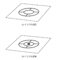
これにより、墨位置確認針50´の先端52´からインクを供給しない場合には、図5(a)に示すように、中心に印影が存在しないが、墨位置確認針50´の先端52からインクを射出した場合には、図5(b)に示すように、中心にも印影が存在する。すなわち、本実施形態の墨位置記録スタンプ60によれば、中心にも墨位置の記録を行うことが可能となる。
Thus, when ink is not supplied from the tip 52 'of the black position confirmation needle 50', as shown in FIG. 5A, there is no imprint at the center, but from the
以上説明したように、本実施形態の墨位置記録スタンプ60によれば、墨位置確認針50´が中空に形成されており、その先端52´からインクを射出可能となっているので、印面31(パターン)の中心での墨位置記録を実現でき、これにより、より高精度の墨位置記録を実現できる。
As described above, according to the black
なお、墨位置確認針50´の基端51´に、インク供給管70に代えて、光(例えばレーザ光)供給管を接続し、その先端52´から光(例えばレーザ光)を照射するようにしてもよい。
In addition, instead of the
このようにすれば、墨位置確認針50´の軸心が壁面等の墨位置記録対象面のどの位置に投影されるかを示すことができる。したがって、この墨位置記録スタンプ60を平行移動可能なXYアームと上下方向に移動可能なエアシリンダに取付ければ、特願2005−204452号に記載のマーキング機構の様に、壁面等の墨位置記録対象面に接触することなく墨位置の確認ができるマーキング装置の一部品として使用することが可能となる。また、離れた場所からでも記録を行う墨位置の確認を効率よく行うことが可能となる。
In this way, it is possible to indicate on which position of the black position recording target surface such as the wall surface the axis of the black position confirmation needle 50 'is projected. Therefore, if the black
上記実施形態はあらゆる点で単なる例示にすぎない。これらの記載によって本発明は限定的に解釈されるものではない。本発明はその精神または主要な特徴から逸脱することなく他の様々な形で実施することができる。 The above embodiment is merely an example in all respects. The present invention is not construed as being limited to these descriptions. The present invention can be implemented in various other forms without departing from the spirit or main features thereof.
10…墨位置記録スタンプ、20…スタンプ本体、30…スタンプ部、31…印面、32…貫通孔、40…弾性部材、50…墨位置確認針、51…基端、52…先端、53…貫通孔、60…墨位置記録スタンプ、70…インク供給管、K…空間、M…墨位置記録対象面、P…プレート
DESCRIPTION OF
Claims (4)
前記筒体に設けられており、墨位置を特定させるためのパターンを有する印面とその印面の反対側の裏面とを有するとともに前記印面と前記裏面とを貫通する貫通孔が形成されたスタンプ部と、
前記筒体内に配置された弾性部材と、
前記スタンプ部に形成された貫通孔に挿入されており、前記弾性部材により付勢されて突出させられる墨位置確認針と、
を備えており、
前記墨位置確認針の突出部分は、この突出部分に加えられる力により前記弾性部材が弾性変形させられて、前記筒体内に収納されることを特徴とする墨位置記録スタンプ。 A bottomed cylinder,
A stamp portion provided in the cylinder, having a marking surface having a pattern for specifying a black position and a back surface opposite to the marking surface, and having a through-hole penetrating the marking surface and the back surface; ,
An elastic member disposed in the cylinder;
Inserted in a through-hole formed in the stamp portion, and a black position confirmation needle that is biased and protruded by the elastic member;
With
The black position recording stamp is characterized in that the protruding portion of the black position confirmation needle is housed in the cylinder by elastically deforming the elastic member by a force applied to the protruding portion.
前記貫通孔は、前記パターンの中心位置に形成されていることを特徴とする請求項1に記載の墨位置記録スタンプ。 The pattern for specifying the black position is a pattern in which the center position is easy to estimate but the center is hollow,
2. The black position recording stamp according to claim 1, wherein the through hole is formed at a center position of the pattern.
Priority Applications (1)
| Application Number | Priority Date | Filing Date | Title |
|---|---|---|---|
| JP2006263457A JP2008080452A (en) | 2006-09-27 | 2006-09-27 | Marking position recording stamp |
Applications Claiming Priority (1)
| Application Number | Priority Date | Filing Date | Title |
|---|---|---|---|
| JP2006263457A JP2008080452A (en) | 2006-09-27 | 2006-09-27 | Marking position recording stamp |
Publications (1)
| Publication Number | Publication Date |
|---|---|
| JP2008080452A true JP2008080452A (en) | 2008-04-10 |
Family
ID=39351816
Family Applications (1)
| Application Number | Title | Priority Date | Filing Date |
|---|---|---|---|
| JP2006263457A Withdrawn JP2008080452A (en) | 2006-09-27 | 2006-09-27 | Marking position recording stamp |
Country Status (1)
| Country | Link |
|---|---|
| JP (1) | JP2008080452A (en) |
Cited By (1)
| Publication number | Priority date | Publication date | Assignee | Title |
|---|---|---|---|---|
| CN106989740A (en) * | 2017-05-25 | 2017-07-28 | 深圳市洪涛装饰股份有限公司 | A kind of indoor ceiling telltale mark instrument and its marker |
Citations (9)
| Publication number | Priority date | Publication date | Assignee | Title |
|---|---|---|---|---|
| JPS416412Y1 (en) * | 1964-04-23 | 1966-04-01 | ||
| JPS50112141A (en) * | 1973-10-29 | 1975-09-03 | ||
| JPS5729359A (en) * | 1980-06-12 | 1982-02-17 | Avicon Inc | Fibrous collagen stanching-adhesive cloth |
| JPH0639750A (en) * | 1992-04-20 | 1994-02-15 | Mirai Ind Co Ltd | Marking device for marking on ceiling surface one point on floor surface irradiated vertically upward by means of beam |
| JPH0663875A (en) * | 1992-08-14 | 1994-03-08 | K S Planning:Kk | Marking device for ceiling, wall surfaces, etc. |
| KR970014943A (en) * | 1995-09-29 | 1997-04-28 | 전성원 | Point indicator for body rigidity test |
| JPH10244478A (en) * | 1997-02-28 | 1998-09-14 | Honda Motor Co Ltd | Laying-out needle having ink |
| JP2000199712A (en) * | 1999-01-06 | 2000-07-18 | Masayuki Asano | Device for marking on ceilling surface |
| JP2002346956A (en) * | 2001-05-28 | 2002-12-04 | Honda Motor Co Ltd | Laser scriber |
-
2006
- 2006-09-27 JP JP2006263457A patent/JP2008080452A/en not_active Withdrawn
Patent Citations (9)
| Publication number | Priority date | Publication date | Assignee | Title |
|---|---|---|---|---|
| JPS416412Y1 (en) * | 1964-04-23 | 1966-04-01 | ||
| JPS50112141A (en) * | 1973-10-29 | 1975-09-03 | ||
| JPS5729359A (en) * | 1980-06-12 | 1982-02-17 | Avicon Inc | Fibrous collagen stanching-adhesive cloth |
| JPH0639750A (en) * | 1992-04-20 | 1994-02-15 | Mirai Ind Co Ltd | Marking device for marking on ceiling surface one point on floor surface irradiated vertically upward by means of beam |
| JPH0663875A (en) * | 1992-08-14 | 1994-03-08 | K S Planning:Kk | Marking device for ceiling, wall surfaces, etc. |
| KR970014943A (en) * | 1995-09-29 | 1997-04-28 | 전성원 | Point indicator for body rigidity test |
| JPH10244478A (en) * | 1997-02-28 | 1998-09-14 | Honda Motor Co Ltd | Laying-out needle having ink |
| JP2000199712A (en) * | 1999-01-06 | 2000-07-18 | Masayuki Asano | Device for marking on ceilling surface |
| JP2002346956A (en) * | 2001-05-28 | 2002-12-04 | Honda Motor Co Ltd | Laser scriber |
Cited By (1)
| Publication number | Priority date | Publication date | Assignee | Title |
|---|---|---|---|---|
| CN106989740A (en) * | 2017-05-25 | 2017-07-28 | 深圳市洪涛装饰股份有限公司 | A kind of indoor ceiling telltale mark instrument and its marker |
Similar Documents
| Publication | Publication Date | Title |
|---|---|---|
| FI20021060A0 (en) | Arrangement for fire-fighting | |
| EP1628161A3 (en) | Lithographic apparatus and device manufacturing method | |
| EP1749674A3 (en) | Print apparatus, ribbon movement control device, ribbon film, ribbon movement control method, and program | |
| JP2008080452A (en) | Marking position recording stamp | |
| US20170136577A1 (en) | Method for Welding a Ball onto a First Component, and Method for Connecting Two Components | |
| JP5663847B2 (en) | Calibration jig and calibration method | |
| JP2005249182A (en) | Component fixture and temporary holding mechanism of component fixture to nailing machine | |
| JP2006320934A (en) | Pressing device | |
| JP2019089181A (en) | Assembling device and method for assembling with assembling device | |
| JPH0976168A (en) | Jig for bearing insertion | |
| JP4486018B2 (en) | Armature damper, armature damper manufacturing method and dot head | |
| JP2010114309A (en) | Flux transfer head, and flux transfer device | |
| JP2010054773A (en) | Method for removing foreign material and method for manufacturing semiconductor device | |
| JP2008251232A (en) | Collector apparatus | |
| CN215701512U (en) | Micro-motion auxiliary platform for assembling mobile phone camera welding ring | |
| JP5013344B2 (en) | Perforated parts feeder | |
| JP2014237079A (en) | Nozzle position adjustment jig | |
| JP2008105174A (en) | Method and device for holding plastic fastening element in always usable state and plastic fastening element | |
| JP2006055956A (en) | Fitting apparatus, fitting means, and fitting method | |
| JP5135936B2 (en) | Writing instrument clip | |
| JPH0639750A (en) | Marking device for marking on ceiling surface one point on floor surface irradiated vertically upward by means of beam | |
| JP2011062744A (en) | Roll changing device | |
| CN113119042A (en) | Micro-motion auxiliary platform for assembling mobile phone camera welding ring | |
| JP2006205523A (en) | Writing implement support device and drawing equipment | |
| JP2531007B2 (en) | Depth measuring method and measuring device |
Legal Events
| Date | Code | Title | Description |
|---|---|---|---|
| A621 | Written request for application examination |
Free format text: JAPANESE INTERMEDIATE CODE: A621 Effective date: 20080912 |
|
| A131 | Notification of reasons for refusal |
Free format text: JAPANESE INTERMEDIATE CODE: A131 Effective date: 20110902 |
|
| A761 | Written withdrawal of application |
Free format text: JAPANESE INTERMEDIATE CODE: A761 Effective date: 20111003 |