JP2008077458A - Storage data processing device, storage device, storage data processing program - Google Patents
Storage data processing device, storage device, storage data processing program Download PDFInfo
- Publication number
- JP2008077458A JP2008077458A JP2006256752A JP2006256752A JP2008077458A JP 2008077458 A JP2008077458 A JP 2008077458A JP 2006256752 A JP2006256752 A JP 2006256752A JP 2006256752 A JP2006256752 A JP 2006256752A JP 2008077458 A JP2008077458 A JP 2008077458A
- Authority
- JP
- Japan
- Prior art keywords
- data
- block
- calculation
- management information
- sector
- Prior art date
- Legal status (The legal status is an assumption and is not a legal conclusion. Google has not performed a legal analysis and makes no representation as to the accuracy of the status listed.)
- Pending
Links
Images

Classifications
-
- G—PHYSICS
- G06—COMPUTING OR CALCULATING; COUNTING
- G06F—ELECTRIC DIGITAL DATA PROCESSING
- G06F11/00—Error detection; Error correction; Monitoring
- G06F11/07—Responding to the occurrence of a fault, e.g. fault tolerance
- G06F11/08—Error detection or correction by redundancy in data representation, e.g. by using checking codes
- G06F11/10—Adding special bits or symbols to the coded information, e.g. parity check, casting out 9's or 11's
- G06F11/1076—Parity data used in redundant arrays of independent storages, e.g. in RAID systems
-
- G—PHYSICS
- G11—INFORMATION STORAGE
- G11B—INFORMATION STORAGE BASED ON RELATIVE MOVEMENT BETWEEN RECORD CARRIER AND TRANSDUCER
- G11B20/00—Signal processing not specific to the method of recording or reproducing; Circuits therefor
- G11B20/10—Digital recording or reproducing
- G11B20/18—Error detection or correction; Testing, e.g. of drop-outs
- G11B20/1833—Error detection or correction; Testing, e.g. of drop-outs by adding special lists or symbols to the coded information
-
- G—PHYSICS
- G06—COMPUTING OR CALCULATING; COUNTING
- G06F—ELECTRIC DIGITAL DATA PROCESSING
- G06F2211/00—Indexing scheme relating to details of data-processing equipment not covered by groups G06F3/00 - G06F13/00
- G06F2211/10—Indexing scheme relating to G06F11/10
- G06F2211/1002—Indexing scheme relating to G06F11/1076
- G06F2211/1092—Single disk raid, i.e. RAID with parity on a single disk
-
- G—PHYSICS
- G11—INFORMATION STORAGE
- G11B—INFORMATION STORAGE BASED ON RELATIVE MOVEMENT BETWEEN RECORD CARRIER AND TRANSDUCER
- G11B2220/00—Record carriers by type
- G11B2220/20—Disc-shaped record carriers
- G11B2220/25—Disc-shaped record carriers characterised in that the disc is based on a specific recording technology
- G11B2220/2508—Magnetic discs
- G11B2220/2516—Hard disks
Landscapes
- Engineering & Computer Science (AREA)
- Theoretical Computer Science (AREA)
- Signal Processing (AREA)
- Quality & Reliability (AREA)
- Physics & Mathematics (AREA)
- General Engineering & Computer Science (AREA)
- General Physics & Mathematics (AREA)
- Signal Processing For Digital Recording And Reproducing (AREA)
Abstract
【課題】上位装置への応答時間の増加を抑えつつ、エラーリカバリ能力を向上させる記憶装置、記憶データ処理装置、記憶データ処理プログラムを提供する。
【解決手段】記憶媒体において第2ブロック毎に、第2ブロックに対応する第3ブロックが有効か無効かの情報を含む管理情報を記憶する管理情報記憶部と、管理情報記憶部に記憶された管理情報において、更新対象として指定された第2ブロックに対応する第3ブロックが無効である場合、更新対象中の全ての第1ブロックのデータについてビット位置毎の演算を行い、演算の結果を演算データとして出力する演算部と、演算部により出力された演算データを、更新対象に対応付けられた第3ブロックへ書き込み、管理情報記憶部に記憶された管理情報において第3ブロックを有効とする書き込み部とを備えた。
【選択図】図1Provided are a storage device, a storage data processing device, and a storage data processing program that improve error recovery capability while suppressing an increase in response time to a host device.
A management information storage unit for storing management information including information on whether a third block corresponding to the second block is valid or invalid for each second block in the storage medium, and the management information storage unit stores the management information. In the management information, when the third block corresponding to the second block designated as the update target is invalid, the calculation is performed for each bit position on the data of all the first blocks being updated, and the calculation result is calculated. A calculation unit that outputs data, and calculation data output by the calculation unit is written to the third block associated with the update target, and the third block is enabled in the management information stored in the management information storage unit And equipped with.
[Selection] Figure 1
Description
本発明は、読み出しエラーのリカバリを行う記憶装置、それに用いられる記憶データ処理装置、記憶データ処理プログラムに関するものである。 The present invention relates to a storage device that performs recovery of a read error, a storage data processing device used therefor, and a storage data processing program.
近年、ハードディスク装置(HDD:Hard Disk Drive)の記録容量は増加の傾向にあり、一つのハードディスク装置で200GB以上の容量を保有するようになってきている。これに伴い、一つのセクタが読み出しエラーとなった場合の被害は大きくなっている。特にハードディスク装置内のデータ管理に関するディレクトリ情報が記録されている箇所に該当するセクタが一つ読み出しエラーとなった場合などにおいては、被害を受けるデータが更に膨大になる。また、この深刻度は容量が増すほど増える。 In recent years, the recording capacity of a hard disk drive (HDD) has been increasing, and one hard disk device has a capacity of 200 GB or more. Along with this, the damage when a read error occurs in one sector is increasing. In particular, when one sector corresponding to a location where directory information related to data management in the hard disk device is recorded results in a read error, the data to be damaged further increases. Also, this severity increases with increasing capacity.
従来、このようなハードディスク装置固有の障害を避ける手段として、ハードディスク装置をアレイとして構築するシステムが用意されている。このシステムにおいては、読み出しエラーになったドライブが存在しても、冗長度を高めるために配置されている他のハードディスク装置のデータを使ってリカバリする。ハードディスク装置単体でのエラーへの耐久性を高める方法としては、ECC(Error Correcting Code)をセクタ内の情報に付加する方式がとられている。ここで、ディスク媒体上の各セクタは、SB(syncbyte)、DATA、ECCで構成されている。 Conventionally, systems for constructing hard disk devices as an array have been prepared as means for avoiding such problems inherent to the hard disk devices. In this system, even if there is a drive having a read error, recovery is performed using data of another hard disk device arranged to increase redundancy. As a method for enhancing the durability against errors in a single hard disk device, a method of adding ECC (Error Correcting Code) to information in a sector is employed. Here, each sector on the disk medium is composed of SB (syncbyte), DATA, and ECC.
ここで、或るセクタで読み出しエラーが発生した場合を想定する。このとき、ハードディスク装置内のデータバッファには、読み出しを開始した時点のセクタのデータから読み出しエラーが起きたセクタの手前のセクタまでのデータが保持されている。そして、読み出しエラーが起きたセクタのデータ読み出しがリトライでも成功しない場合、ハードディスク装置は、有効なデータをデータバッファに取り込めないために上位装置におくることができず、最終的にデータのリカバリ処理に失敗すると、上位装置に対して読み出しエラーを通知し、終了していた。 Here, it is assumed that a read error occurs in a certain sector. At this time, the data buffer in the hard disk device holds data from the data of the sector at the time of starting reading to the sector before the sector where the read error occurred. If the data read of the sector in which the read error has occurred is not successful even after retrying, the hard disk device cannot be placed in the host device because it cannot capture valid data into the data buffer, and eventually the data recovery process If it failed, the host device was notified of a read error and ended.
なお、本発明の関連ある従来技術として、トラックサイズ分のバッファを用意し、トラック単位でのデータチェック処理を行うファイル制御装置がある(例えば、特許文献1参照)。また、セクタ毎にLDC(Long Distance Code)のパリティを付加し、所定のセクタ数毎にパリティセクタデータを付加し、所定のセクタ毎にパリティセクタデータを算出し、再生時にLDCのパリティによる訂正が不能となった場合にパリティセクタデータを用いて訂正を行うデータ記録方法がある(例えば、特許文献2参照)。
ECCによる訂正能力そのものは緩やかに向上してきてはいるが、新しいデータ訂正方式などは採用されておらず、近年は同じ技術が用いられ続けている。しかしながら、ハードディスク装置単体の記録容量が増加する傾向にある中で、従来のECCによるデータ訂正能力では、相対的にデータ喪失の危険が増してきていると言える。 Although the correction capability by ECC itself has been gradually improved, no new data correction method has been adopted, and the same technology has been used in recent years. However, while the recording capacity of a single hard disk device tends to increase, it can be said that the risk of data loss is relatively increasing with the conventional data correction capability using ECC.
また、上述したように従来のハードディスク装置において、ECCで訂正できない場合に、エラーを上位装置に対して通知し、終了する、という仕組みはディスク装置の誕生以来ほとんど変わってない。 Further, as described above, in a conventional hard disk device, when ECC cannot be corrected, a mechanism for notifying an error to a higher-level device and terminating is almost unchanged since the birth of the disk device.
また、特許文献1のような技術は、書き込み処理を行うたびにトラック分のデータを読み出さなければならず、コマンドの処理時間が約2倍に増加し、性能が低下するため、現実的に使用することは困難である。また、特許文献2のような技術は、上位装置から書き込みデータを受領したときに冗長データを用意しなければならず、性能が低下するため、現実的に使用することは困難である。
In addition, the technique as in
本発明は上述した問題点を解決するためになされたものであり、エラーリカバリ能力を向上させる記憶装置、それに用いられる記憶データ処理装置、記憶データ処理プログラムを提供することを目的とする。 The present invention has been made to solve the above-described problems, and an object thereof is to provide a storage device that improves error recovery capability, a storage data processing device used in the storage device, and a storage data processing program.
上述した課題を解決するため、本発明は、所定のデータ長の第1ブロックを単位としてデータが配置され、且つ複数の前記第1ブロックで構成される第2ブロックを単位として前記第1ブロックが配置され、且つ前記第2ブロックに対応して前記第1ブロック長を持つ第3ブロックが配置される記憶媒体に対して少なくとも書き込み処理を行う記憶装置に用いられる記憶データ処理装置において、前記第2ブロック毎に、該第2ブロックに対応する第3ブロックが有効か無効かの情報を含む管理情報を記憶する管理情報記憶部と、前記管理情報記憶部に記憶された管理情報において、更新対象として指定された第2ブロックに対応する第3ブロックが無効である場合、前記更新対象中の全ての第1ブロックのデータについてビット位置毎の演算を行い、該演算の結果を演算データとして出力する演算部と、前記演算部により出力された演算データを、前記更新対象に対応付けられた第3ブロックへ書き込み、前記管理情報記憶部に記憶された管理情報において該第3ブロックを有効とする書き込み部とを備えたものである。 In order to solve the above-described problem, the present invention provides data that is arranged in units of a first block having a predetermined data length, and in which the first block is in units of a second block composed of a plurality of the first blocks. In the stored data processing device used for a storage device that is arranged and performs at least a writing process on a storage medium in which the third block having the first block length corresponding to the second block is arranged, the second For each block, in the management information storage unit that stores management information including information on whether the third block corresponding to the second block is valid or invalid, and the management information stored in the management information storage unit, If the third block corresponding to the designated second block is invalid, the data of all the first blocks being updated are represented by bit positions. The calculation unit that outputs the calculation result as calculation data, and the calculation data output by the calculation unit are written to the third block associated with the update target and stored in the management information storage unit The management information includes a writing unit that validates the third block.
また、本発明に係る記憶データ処理装置において、前記演算部は、前記演算データを初期化し、前記更新対象中の各々の第1ブロックのデータを順次、前記演算の入力データとし、該入力データと前記演算データについてビット位置毎の演算を行い、該演算の結果を新たな演算データとして記憶し、該演算と該記憶を全ての前記入力データについて繰り返し、前記演算データを出力することを特徴とする。 Further, in the stored data processing apparatus according to the present invention, the calculation unit initializes the calculation data, and sequentially sets each first block data being updated as input data for the calculation, The calculation data is calculated for each bit position, the calculation result is stored as new calculation data, the calculation and the storage are repeated for all the input data, and the calculation data is output. .
また、本発明に係る記憶データ処理装置において、更に、読み出し対象として指定された第1ブロックからデータを読み出し、該データの読み出しに失敗した場合、前記読み出しに失敗した第1ブロックをエラーブロックとし、前記管理情報記憶部に記憶された管理情報において前記読み出し対象を含む第2ブロックに対応する第3ブロックが有効である場合、該第2ブロック中の該エラーブロック以外の全ての第1ブロックのデータである正常データを読み出し、該第2ブロックに対応する第3ブロックのデータである冗長データを読み出す読み出し部を備え、前記演算部は更に、前記正常データと前記冗長データについてビット位置毎の演算を行い、該演算の結果を前記エラーブロックのデータとして出力することを特徴とする。 Further, in the stored data processing device according to the present invention, when data is read from the first block designated as a read target and reading of the data fails, the first block that has failed to be read is set as an error block, When the third block corresponding to the second block including the read target is valid in the management information stored in the management information storage unit, the data of all the first blocks other than the error block in the second block And reading out the redundant data which is the data of the third block corresponding to the second block, and the calculation unit further performs calculation for each bit position of the normal data and the redundant data. And the result of the operation is output as data of the error block.
また、本発明に係る記憶データ処理装置において、前記演算部は、前記演算データを初期化し、各々の前記正常データと前記冗長データを順次、前記演算の入力データとし、該入力データと前記演算データについてビット位置毎の演算を行い、該演算の結果を新たな演算データとして記憶し、該演算と該記憶を全ての前記入力データについて繰り返し、前記演算データを出力することを特徴とする。 Further, in the stored data processing device according to the present invention, the calculation unit initializes the calculation data, and sequentially sets the normal data and the redundant data as input data for the calculation. The input data and the calculation data The calculation is performed for each bit position, the result of the calculation is stored as new calculation data, the calculation and the storage are repeated for all the input data, and the calculation data is output.
また、本発明に係る記憶データ処理装置において、前記書き込み部は、外部装置からのデータ書き込み指示を受けた場合、前記データ書き込み命令によるデータ書き込み対象を含む第2ブロックに対応する第3ブロックについて、前記管理情報記憶部に記憶された管理情報において該第3ブロックを有効とすることを特徴とする。 Further, in the stored data processing apparatus according to the present invention, when the writing unit receives a data write instruction from an external device, the third block corresponding to the second block including the data write target by the data write command, The third block is validated in the management information stored in the management information storage unit.
また、本発明に係る記憶データ処理装置において、前記演算部は、外部装置からのデータ読み出し指示またはデータ書き込み指示による処理を行っていないときに、前記管理情報記憶部に記憶された管理情報において無効である第3ブロックに対応する第2ブロックについて前記演算を行うことを特徴とする。 Further, in the stored data processing device according to the present invention, the arithmetic unit is invalid in the management information stored in the management information storage unit when the processing according to the data read instruction or the data write instruction from the external device is not performed. The calculation is performed on the second block corresponding to the third block.
また、本発明に係る記憶データ処理装置において、前記管理情報記憶部は、不揮発性メモリであることを特徴とする。 In the stored data processing apparatus according to the present invention, the management information storage unit is a nonvolatile memory.
また、本発明に係る記憶データ処理装置において、前記管理情報記憶部は、外部装置からライトキャッシュデータを前記記憶媒体上に書き込む指示、またはヘッドを退避させる指示を受領した場合、前記管理情報を前記記憶媒体に書き込むことを特徴とする。 In the storage data processing device according to the present invention, when the management information storage unit receives an instruction to write write cache data on the storage medium or an instruction to evacuate a head from an external device, the management information storage unit It is characterized by writing to a storage medium.
また、本発明に係る記憶データ処理装置において、前記管理情報は、前記第2ブロック毎に、該第2ブロックに含まれる複数の第1ブロックの指定を含むことを特徴とする。 In the stored data processing apparatus according to the present invention, the management information includes designation of a plurality of first blocks included in the second block for each second block.
また、本発明に係る記憶データ処理装置において、前記管理情報は、前記第2ブロック毎に、該第2ブロックに含まれる複数の第1ブロックの指定を含み、前記書き込み部は、前記管理情報に基づいて前記第2ブロックを前記記憶媒体に配置することを特徴とする。 In the storage data processing device according to the present invention, the management information includes designation of a plurality of first blocks included in the second block for each second block, and the writing unit includes the management information in the management information. Based on this, the second block is arranged in the storage medium.
また、本発明に係る記憶データ処理装置において、前記管理情報記憶部は、外部装置から各々の第2ブロックへのアクセス頻度に基づいて第2ブロックに含まれる複数の第1ブロックの数を決定し、前記管理情報に含めることを特徴とする。 In the stored data processing device according to the present invention, the management information storage unit determines the number of the plurality of first blocks included in the second block based on an access frequency from the external device to each second block. And included in the management information.
また、本発明に係る記憶データ処理装置において、前記演算部による演算は、順次演算を行う順序を変えても演算結果が変わらない演算であることを特徴とする。 In the stored data processing apparatus according to the present invention, the calculation by the calculation unit is a calculation in which the calculation result does not change even if the order of sequential calculation is changed.
また、本発明に係る記憶データ処理装置において、前記演算部による演算は、排他的論理和であることを特徴とする。 In the stored data processing apparatus according to the present invention, the calculation by the calculation unit is an exclusive OR.
また、本発明に係る記憶データ処理装置において、前記第1ブロックは、少なくとも1つのセクタであり、前記第3ブロックは、前記第1ブロック長を持ち、前記演算データは、前記第1ブロック長を持つことを特徴とする。 In the stored data processing apparatus according to the present invention, the first block is at least one sector, the third block has the first block length, and the operation data has the first block length. It is characterized by having.
また、本発明は、記憶装置における記憶データ処理をコンピュータに実行させる記憶データ処理プログラムにおいて、所定のデータ長の第1ブロックを単位としてデータが配置され、且つ複数の前記第1ブロックで構成される第2ブロックを単位として前記第1ブロックが配置され、且つ前記第2ブロックに対応して前記第1ブロック長を持つ第3ブロックが配置される記憶媒体について、前記第2ブロック毎に、該第2ブロックに対応する第3ブロックが有効か無効かの情報を含む管理情報を記憶する管理情報記憶ステップと、前記管理情報記憶ステップにより記憶された管理情報において、更新対象として指定された第2ブロックに対応する第3ブロックが無効である場合、前記更新対象中の全ての第1ブロックのデータについてビット位置毎の演算を行い、該演算の結果を演算データとして出力する演算ステップと、前記演算ステップにより出力された演算データを、前記更新対象に対応付けられた第3ブロックへ書き込み、前記管理情報記憶ステップにより記憶された管理情報において該第3ブロックを有効とする書き込みステップとをコンピュータに実行させるものである。 According to the present invention, in a stored data processing program for causing a computer to execute stored data processing in a storage device, data is arranged in units of a first block having a predetermined data length, and is configured by a plurality of the first blocks. A storage medium in which the first block is arranged in units of the second block and the third block having the first block length corresponding to the second block is arranged, for each second block, the first block A management information storage step for storing management information including information indicating whether the third block corresponding to two blocks is valid or invalid; and the second block designated as an update target in the management information stored in the management information storage step If the third block corresponding to is invalid, the bit for all the data of the first block being updated A calculation step of performing calculation for each device and outputting the result of the calculation as calculation data; and writing the calculation data output by the calculation step into the third block associated with the update target; In the management information stored in the step, the computer is caused to execute a writing step for validating the third block.
また、本発明は、所定のデータ長の第1ブロックを単位としてデータが配置され、且つ複数の前記第1ブロックで構成される第2ブロックを単位として前記第1ブロックが配置され、且つ前記第2ブロックに対応して前記第1ブロック長を持つ第3ブロックが配置される記憶媒体に対して少なくとも書き込み処理を行う記憶装置において、前記第2ブロック毎に、該第2ブロックに対応する第3ブロックが有効か無効かの情報を含む管理情報を記憶する管理情報記憶部と、前記管理情報記憶部に記憶された管理情報において、更新対象として指定された第2ブロックに対応する第3ブロックが無効である場合、前記更新対象中の全ての第1ブロックのデータについてビット位置毎の演算を行い、該演算の結果を演算データとして出力する演算部と、前記演算部により出力された演算データを、前記更新対象に対応付けられた第3ブロックへ書き込み、前記管理情報記憶部に記憶された管理情報において該第3ブロックを有効とする書き込み部とを備えたものである。 According to the present invention, data is arranged in units of a first block having a predetermined data length, and the first block is arranged in units of a second block composed of a plurality of the first blocks. In a storage device that performs at least write processing on a storage medium in which a third block having the first block length corresponding to two blocks is arranged, a third block corresponding to the second block is provided for each second block. A management information storage unit that stores management information including information indicating whether the block is valid or invalid, and a third block corresponding to a second block designated as an update target in the management information stored in the management information storage unit includes: When invalid, an operation is performed for each bit position on the data of all the first blocks being updated, and the result of the operation is output as operation data And a write unit that writes the calculation data output by the calculation unit to the third block associated with the update target and validates the third block in the management information stored in the management information storage unit; It is equipped with.
本発明によれば、エラーリカバリ能力を向上させて、高密度記録化に伴うデータ記憶の信頼性が高い記憶装置、それに用いられる記憶データ処理装置、記憶データ処理プログラムを提供することができる。 ADVANTAGE OF THE INVENTION According to this invention, error recovery capability can be improved and the memory | storage device with high reliability of the data storage accompanying high-density recording, the memory | storage data processing apparatus used for it, and a memory | storage data processing program can be provided.
以下、本発明の実施の形態について図面を参照しつつ説明する。 Embodiments of the present invention will be described below with reference to the drawings.
実施の形態1.
本実施の形態においては、本発明の記憶データ処理装置及び記憶装置をハードディスク装置に適用した例について説明する。
In the present embodiment, an example in which a storage data processing device and a storage device of the present invention are applied to a hard disk device will be described.
まず、本実施の形態に係るハードディスク装置の構成について説明する。 First, the configuration of the hard disk device according to the present embodiment will be described.
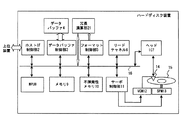
図1は、本実施の形態に係るハードディスク装置の構成の一例を示すブロック図である。 FIG. 1 is a block diagram showing an example of the configuration of the hard disk device according to the present embodiment.
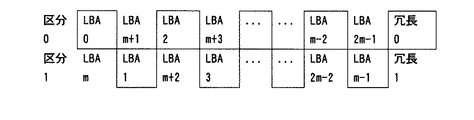
次に、従来のハードディスク装置について説明する。このハードディスク装置は、外部と接続するためのホストIF(Interface)を制御するホストIF制御部2、データバッファ制御部3、データバッファ4、フォーマット制御部5、リードチャネル6、ヘッドIC(Integrated Circuit)7、ハードディスク装置の制御用のMPU(Micro Processing Unit)8、制御用のデータおよび制御用プログラムを格納するメモリ9、制御用プログラムを格納する不揮発性メモリ(FROM)10、スピンドルモータ(SPM)やヴォイスコイルモータ(VCM)の動作を制御するサーボ制御部11、ヘッドアクチュエータを実際に動かすVCM12、ディスクを回転させるSPM13、Read/Write用のヘッド14、ディスク媒体15、内部のコモンバス16、冗長演算部21を備える。
Next, a conventional hard disk device will be described. This hard disk device includes a host
また、ハードディスク装置は、ホストIF制御部2に接続されるホストIFを介して、PC(Personal Computer)等の上位装置(外部装置)に接続される。ホストIF制御部2、データバッファ制御部3、データバッファ4、フォーマット制御部5、リードチャネル6、ヘッドIC7、MPU8、メモリ9、不揮発性メモリ10、サーボ制御部11は、コモンバス16により接続されている。
The hard disk device is connected to a host device (external device) such as a PC (Personal Computer) via a host IF connected to the host
ハードディスク装置から上位装置へのデータの読み出しにおいて、上位装置からの読み出し命令に従って、データはディスク媒体15から読み出され、ヘッド14、およびヘッドIC7を経由してリードチャネル6に送られる。さらに、そのデータは、フォーマット制御部5を経由してECC計算が行われ、エラーの起きなかったデータだけが、データバッファ制御部3を経由してデータバッファ4にいったん保持される。そして、再びデータバッファ制御部3およびホストIF制御部2を経由して上位装置に送られる。
In reading data from the hard disk device to the host device, the data is read from the
また、上位装置からハードディスク装置へのデータの書き込みにおいて、上位装置から書き込み命令として送られたデータは、ホストIF制御部2を経由し、データバッファ制御部3を経由して、いったんデータバッファ4に取り込まれる。さらに、そのデータは、書き込みを実施するのに適当なタイミングで、再びデータバッファ制御部3を経由し、フォーマット制御部5、リードチャネル6、ヘッドIC7を経由してディスク媒体15に書き込まれる。
In writing data from the host device to the hard disk device, data sent as a write command from the host device passes through the host IF
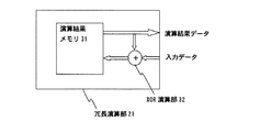
図2は、本実施の形態に係る冗長演算部の構成の一例を示すブロック図である。冗長演算部21は、演算結果メモリ31、XOR(Exclusive OR:排他的論理和)演算部32を備える。演算結果メモリ31は、セクタサイズの容量を持ち、1セクタ分の演算結果データ(演算データ)を保持する。外部からの1セクタ分の入力データと演算結果メモリ31に保持された1セクタ分の演算結果データは、XOR演算部32によりビット位置毎のXOR演算が行われる。この演算結果は、新たな演算結果データとして演算結果メモリ31に保持される。また、MPU8は、演算結果メモリ31に保持された演算結果データを、コモンバス16を介して読み出し、冗長セクタデータとすることができる。
FIG. 2 is a block diagram showing an example of the configuration of the redundant calculation unit according to the present embodiment. The
次に、ディスク媒体15上のユーザ領域におけるセクタ配置について説明する。
Next, the sector arrangement in the user area on the
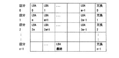
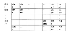
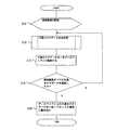
図3は、本実施の形態に係るディスク媒体上のユーザ領域におけるセクタ配置の一例を示す配置図である。この図は、通常のユーザデータが書き込まれる通常セクタと冗長セクタデータが書き込まれる冗長セクタの配置を示す。また、この図における1つの要素は、1つのセクタを表す。また、この図は、区分を区分番号で表し、通常セクタをLBA(Logical Block Address)で表し、冗長セクタを対応する区分番号で表す。ここでは、連続するm個のLBAを持つ通常セクタが1つの区分とされ、この図において1つの区分は1つの行で表されている。また、ユーザ領域全体は、n個の区分に分けられている。また、区分毎に、その区分のユーザデータに基づく冗長セクタデータを書き込むための1つの冗長セクタが挿入される。つまり、j番目の区分LBA(ji)〜LBA((j+1)i−1)を持つユーザデータに対して1つの冗長セクタデータ(j)が生成され、挿入される(i=0,1,…m−1)(j=0,1,…n−1)。 FIG. 3 is an arrangement diagram showing an example of sector arrangement in the user area on the disk medium according to the present embodiment. This figure shows the arrangement of normal sectors to which normal user data is written and redundant sectors to which redundant sector data is written. Further, one element in this figure represents one sector. Further, in this figure, a partition is represented by a partition number, a normal sector is represented by an LBA (Logical Block Address), and a redundant sector is represented by a corresponding partition number. Here, a normal sector having m consecutive LBAs is defined as one section, and one section is represented by one row in this figure. The entire user area is divided into n sections. Further, for each section, one redundant sector for writing redundant sector data based on the user data of the section is inserted. That is, one redundant sector data (j) is generated and inserted (i = 0, 1,...) For user data having the j-th section LBA (ji) to LBA ((j + 1) i−1). m−1) (j = 0, 1,... n−1).
次に、本実施の形態に係るハードディスク装置の動作について説明する。 Next, the operation of the hard disk device according to the present embodiment will be described.
まず、ディスク媒体15に書き込まれているユーザデータから冗長セクタデータを生成し、冗長セクタデータの書き込みを行う冗長セクタデータ更新処理について説明する。
First, redundant sector data update processing for generating redundant sector data from user data written on the
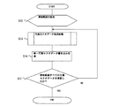
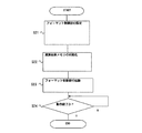
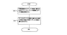
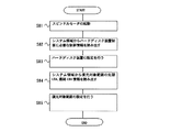
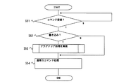
冗長セクタデータ更新処理は、上位装置からの更新指示を受けた場合、または、上位装置からのアクセスがない期間(MPU8の空き時間)が閾値を超えた場合に実行される。図4は、本実施の形態に係る冗長セクタデータ更新処理の動作の一例を示すフローチャートである。まず、MPU8は、ユーザ領域の全てを更新範囲として設定する(S12)。次に、MPU8は、更新範囲において区分毎に冗長セクタデータ生成処理を行い(S13)、生成した1つの冗長セクタデータをディスク媒体15に書き込む単一冗長セクタデータ書き込み処理を行う(S14)。次に、MPU8は、更新範囲の全ての区分の冗長セクタデータを更新したか否かの判断を行い、全てを更新していない場合(S17,N)、処理S13へ戻り、全てを更新した場合(S17,Y)、このフローは終了する。 The redundant sector data update processing is executed when an update instruction is received from a higher-level device, or when a period when there is no access from the higher-level device (empty time of the MPU 8) exceeds a threshold value. FIG. 4 is a flowchart showing an example of the operation of the redundant sector data update process according to the present embodiment. First, the MPU 8 sets the entire user area as an update range (S12). Next, the MPU 8 performs redundant sector data generation processing for each section in the update range (S13), and performs single redundant sector data write processing for writing the generated single redundant sector data to the disk medium 15 (S14). Next, the MPU 8 determines whether or not the redundant sector data of all sections in the update range has been updated. If not all have been updated (S17, N), the process returns to step S13 and all have been updated. (S17, Y), this flow ends.
次に、処理S13の冗長セクタデータ生成処理について説明する。 Next, the redundant sector data generation process of process S13 will be described.
冗長セクタデータ生成処理は、対象の区分のユーザデータを読み出し、冗長演算部21によりユーザデータから冗長セクタデータを生成する処理である。図5は、本実施の形態に係る冗長セクタデータ生成処理の動作の一例を示すフローチャートである。まず、MPU8は、対象の区分の先頭LBA及び最終LBA、処理対象セクタ数、セクタ配置をフォーマット制御部5に設定する(S21)。セクタ配置は、冗長セクタデータの生成に用いる通常セクタの配置を示し、読み出す通常セクタの順序を指定するものである。ここでは、上述したように対象の区分内の通常セクタは連続して配置されており、MPU8は、連続する通常セクタを読み出すようにセクタ配置を指定する。次に、MPU8は、冗長演算部21の演算結果メモリ31を初期化(0クリア)する(S22)。次に、MPU8は、フォーマット制御部5を起動し、対象のユーザデータを読み出させ、冗長演算部21へ入力させる(S23)。次に、MPU8は、動作が終了したか否かの判断を行い、動作が終了していない場合(S24,N)、処理S24へ戻り、動作が終了した場合(S24,Y)、このフローは終了する。
The redundant sector data generation process is a process of reading user data in a target section and generating redundant sector data from the user data by the
次に、冗長セクタデータ生成処理中の冗長演算部21の動作について説明する。まず、演算結果メモリ31における1セクタ分のデータは全て0に初期化されるため、最初のユーザデータである入力データは、そのまま演算結果データとして演算結果メモリ31に保持される。その後のユーザデータと演算結果データは、ビット位置毎にXOR演算され、演算結果データとして演算結果メモリ31に上書きされていく。冗長セクタデータ生成処理が終了した時点で、演算結果メモリ31に保持された演算結果データが、冗長セクタデータとなる。
Next, the operation of the
また、最終LBAを含む区分である最終区分は、他の区分より通常セクタの数が少ない場合があるが、冗長セクタデータ生成処理において、区分内の全てのユーザデータが入力データとして入力されれば通常セクタの数に関わらず、冗長セクタデータを得ることができる。 In addition, the final section, which is a section including the final LBA, may have a smaller number of normal sectors than the other sections, but if all user data in the section is input as input data in the redundant sector data generation process, Redundant sector data can be obtained regardless of the number of normal sectors.
次に、単一冗長セクタデータ書き込み処理について説明する。 Next, a single redundant sector data write process will be described.
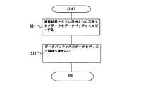
図6は、本実施の形態に係る単一冗長セクタデータ書き込み処理の動作の一例を示すフローチャートである。まず、MPU8は、演算結果メモリ31に保持された冗長セクタデータをデータバッファ4へコピーする(S31)。次に、MPU8は、通常のデータバッファ4内のユーザデータをディスク媒体15に書き込む処理と同様、データバッファ4内の冗長セクタデータをディスク媒体15に書き込み(S32)、このフローは終了する。
FIG. 6 is a flowchart showing an example of the operation of the single redundant sector data write processing according to the present embodiment. First, the MPU 8 copies the redundant sector data held in the calculation result memory 31 to the data buffer 4 (S31). Next, the MPU 8 writes the redundant sector data in the data buffer 4 to the
従来のユーザデータの書き込みと同様にして、データバッファ4からディスク媒体15へ書き込む経路を、冗長セクタデータの書き込みに利用することにより、従来のハードディスク装置に本発明を適用することによるハードウェア規模の増加を少なくすることができる。また、第2冗長セクタデータ更新処理においても、全ての冗長セクタデータを一旦データバッファ4にコピーすることにより、全ての冗長セクタデータを連続して書き込むことができる。
Similar to the conventional writing of user data, the path of writing from the data buffer 4 to the
上述したように、冗長セクタデータの更新は、上位装置からのコマンド(書き込みや読み出しなど)の受領をしていないタイミングで行うことが望ましい。ハードディスク装置において読み出し不可能なエラーセクタが発生するケースは稀であるため、上位装置からのコマンド受領タイミングまたはその直後などに冗長セクタデータの更新を行う必要性は無い。冗長セクタデータの更新の頻度が高いと、処理のオーバヘッドが増加することにより、ハードディスク装置の性能が低下してしまうためである。 As described above, it is desirable to update the redundant sector data at a timing when a command (such as writing or reading) is not received from the host device. Since it is rare that an error sector that cannot be read occurs in the hard disk device, there is no need to update redundant sector data at the timing of command reception from the host device or immediately thereafter. This is because if the frequency of updating the redundant sector data is high, the processing overhead increases, and the performance of the hard disk device is degraded.
次に、ユーザデータ読み出し処理、ディスク媒体走査処理について説明する。 Next, user data reading processing and disk medium scanning processing will be described.
MPU8が上位装置から読み出し命令を受け、対象となる通常セクタの全てが正常に読み出された場合、冗長セクタデータに関する処理は必要とされず、対象のユーザデータを上位装置に送るだけでよい。一方、ユーザデータ読み出し処理において、リカバリできないセクタであるエラーセクタがあった場合、エラーセクタに書き込まれているデータであるエラーセクタデータを復元するエラーセクタデータ復元処理を行う。 When the MPU 8 receives a read command from the host device and all of the target normal sectors are normally read, the processing related to the redundant sector data is not required, and it is only necessary to send the target user data to the host device. On the other hand, when there is an error sector that is a sector that cannot be recovered in the user data read process, an error sector data recovery process is performed to restore error sector data that is data written in the error sector.
また、MPU8が上位装置からディスク媒体走査命令を受けた場合、MPU8は、ディスク媒体15上のユーザ領域における全てのセクタをユーザデータ読み出し処理と同様にして読み出し、エラーセクタの検出を行うディスク媒体走査処理を行う。このディスク媒体走査処理により、エラーセクタがあった場合、ユーザデータ読み出し処理と同様、エラーセクタデータ復元処理を行う。
When the MPU 8 receives a disk medium scan command from the host device, the MPU 8 reads all sectors in the user area on the
また、所定の期間毎に、MPU8は、ディスク媒体15上のユーザ領域における全てのセクタをユーザデータ読み出し処理と同様にして読み出すディスク媒体走査処理を行う。このディスク媒体走査処理により、エラーセクタがあった場合、ユーザデータ読み出し処理と同様、エラーセクタデータ復元処理を行う。
Also, every predetermined period, the MPU 8 performs a disk medium scanning process for reading all sectors in the user area on the
次に、エラーセクタデータ復元処理について説明する。 Next, error sector data restoration processing will be described.
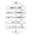
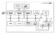
図7は、本実施の形態に係るエラーセクタデータ復元処理の動作の一例を示すフローチャートである。まず、MPU8は、演算結果メモリ31を初期化し(S44)、上述したセクタ配置に従って、ディスク媒体15からエラーセクタが所属する区分内の通常セクタを読み出し、読み出し可能な(エラーセクタデータ以外の)ユーザデータを冗長演算部21へ入力する(S45)。次に、MPU8は、その区分に対応する冗長セクタデータをディスク媒体15から読み出し、冗長演算部21へ入力する(S46)。このとき、冗長演算部21の動作により、演算結果メモリ31における演算結果データは、エラーセクタのデータが復元されたものである復元データとなる。次に、MPU8は、演算結果メモリ31から復元データを読み出し、上位装置に送る(S47)。次に、MPU8は、エラーセクタの代わりに他の空きセクタを割り当てる交代(リアサイン)処理を行い(S48)、このフローは終了する。
FIG. 7 is a flowchart showing an example of operation of error sector data restoration processing according to the present embodiment. First, the MPU 8 initializes the calculation result memory 31 (S44), reads out the normal sector in the section to which the error sector belongs from the
上述したように、対象とする区分内のエラーセクタデータ以外のユーザデータと冗長セクタデータとに対してXOR演算を行うことにより、エラーセクタデータを復元することができる。また、XOR演算部32は、入力データであるセクタの順序を変えても演算結果データが変わらないことから、ある区分について全ての通常セクタのユーザデータをいかなるセクタ順で入力しても、最終的な演算結果データとして冗長セクタデータを得ることができ、エラーセクタが存在数する区分についてエラーセクタデータ以外のユーザデータと冗長セクタデータとをいかなるセクタ順で入力しても、最終的な演算結果データとしてエラーセクタデータを得ることができる。また、最後の区分のように他の区分よりも通常セクタの数が少ない区分であっても、全ての通常セクタのユーザデータを用いることにより他の区分と同様に冗長セクタデータ生成処理とエラーセクタデータ復元処理を行うことができる。 As described above, the error sector data can be restored by performing the XOR operation on the user data other than the error sector data in the target section and the redundant sector data. In addition, since the operation result data does not change even if the order of sectors as input data is changed, the XOR operation unit 32 can finally input user data of all normal sectors in any sector order for a certain section. Redundant sector data can be obtained as correct calculation result data. Even if user data other than error sector data and redundant sector data are input in any sector order for the number of sectors where there are error sectors, the final calculation result data Error sector data can be obtained. Also, even if the number of normal sectors is smaller than the other categories, such as the last category, redundant sector data generation processing and error sectors can be performed in the same way as other categories by using user data of all normal sectors. Data restoration processing can be performed.
なお、本実施の形態においては、冗長セクタデータ生成処理とエラーセクタデータ復元処理のためにXOR演算部32を用いたが、入力データとする複数のセクタの順番を変えても演算結果が変わらない演算であれば、他の演算を用いても良い。また、本実施の形態においては、入力データと演算結果データをセクタ単位としたが、バイト単位、ワード単位など、他のデータ長を単位としても良い。 In this embodiment, the XOR operation unit 32 is used for redundant sector data generation processing and error sector data restoration processing. However, even if the order of a plurality of sectors as input data is changed, the calculation result does not change. Other calculations may be used as long as they are calculations. In the present embodiment, input data and operation result data are in units of sectors, but other data lengths such as in units of bytes or words may be used as units.
本実施の形態によれば、読み出しエラーが発生した場合であっても、エラーセクタのデータを復元することができるため、ディスク装置の信頼性が飛躍的に高まる。また、上位装置からの指示または空き時間に従って、冗長データセクタの更新を行うことにより、上位装置への応答時間の増加を抑えることができる。 According to the present embodiment, even when a read error occurs, the data in the error sector can be restored, so that the reliability of the disk device is dramatically improved. Further, by updating the redundant data sector in accordance with an instruction from the host device or a free time, an increase in response time to the host device can be suppressed.
実施の形態2.
本実施の形態においては、複数の冗長セクタデータをまとめて書き込むハードディスク装置について説明する。
In the present embodiment, a hard disk device that writes a plurality of redundant sector data together will be described.
本実施の形態に係るハードディスク装置の構成は、実施の形態1と同様である。 The configuration of the hard disk device according to the present embodiment is the same as that of the first embodiment.
次に、ディスク媒体15上のユーザ領域におけるセクタ配置について説明する。
Next, the sector arrangement in the user area on the
図8は、本実施の形態に係るディスク媒体上のユーザ領域のセクタ配置の一例を示す配置図である。この場合、実施の形態1に示した全ての通常セクタの後に、全ての冗長セクタが連続して配置される。 FIG. 8 is an arrangement diagram showing an example of the sector arrangement of the user area on the disk medium according to the present embodiment. In this case, all the redundant sectors are continuously arranged after all the normal sectors shown in the first embodiment.
次に、本実施の形態に係るハードディスク装置の動作について説明する。 Next, the operation of the hard disk device according to the present embodiment will be described.
実施の形態1と比較すると、本実施の形態には冗長セクタデータ更新処理が異なる。図9は、本実施の形態に係る冗長セクタデータ更新処理の動作の一例を示すフローチャートである。この図において、図4と同一符号は図4に示された対象と同一又は相当物を示しており、ここでの説明を省略する。処理S13の後、MPU8は、生成されたそれぞれの冗長セクタデータが重ならないように、演算結果メモリ31に保持された冗長セクタデータを一旦データバッファ4に格納する(S15)。次に、MPU8は、更新範囲の全ての冗長セクタデータをデータバッファ4上に格納したか否かの判断を行う(S18)。生成していない場合(S18,N)、処理S13へ戻り、生成した場合(S18,Y)、MPU8は、データバッファ4上の全ての冗長セクタデータを一括してディスク媒体15へ書き込み(S19)、このフローは終了する。
Compared with the first embodiment, the present embodiment differs in redundant sector data update processing. FIG. 9 is a flowchart showing an example of the operation of the redundant sector data update process according to the present embodiment. In this figure, the same reference numerals as those in FIG. 4 denote the same or corresponding parts as those in FIG. 4, and a description thereof will be omitted here. After the process S13, the MPU 8 temporarily stores the redundant sector data held in the operation result memory 31 in the data buffer 4 so that the generated redundant sector data does not overlap (S15). Next, the MPU 8 determines whether or not all redundant sector data in the update range has been stored on the data buffer 4 (S18). If not generated (S18, N), the process returns to step S13. If generated (S18, Y), the MPU 8 writes all the redundant sector data on the data buffer 4 to the
本実施の形態によれば、複数の冗長セクタデータを連続して書き込むことができるため、冗長セクタデータの書き込み時間を短縮することができる。 According to the present embodiment, since a plurality of redundant sector data can be written continuously, the writing time of redundant sector data can be shortened.
実施の形態3.
本実施の形態においては、1つの区分にエラーセクタが2セクタ連続した場合であってもエラーセクタのデータを復元することができるハードディスク装置について説明する。
In the present embodiment, a hard disk device capable of restoring error sector data even when there are two consecutive error sectors in one section will be described.
本実施の形態に係るハードディスク装置の構成は、実施の形態1と同様である。 The configuration of the hard disk device according to the present embodiment is the same as that of the first embodiment.
次に、ディスク媒体15上のユーザ領域におけるセクタ配置について説明する。
Next, the sector arrangement in the user area on the
図10は、本実施の形態に係るディスク媒体上のユーザ領域におけるセクタ配置の一例を示す配置図である。この図は、通常セクタと冗長セクタの配置を示す。また、この図は、区分を区分番号で表し、通常セクタをそのセクタに割り当てられたLBAで表し、冗長セクタを対応する区分番号で表す。ここでは、連続する2m個のLBAを持つユーザデータが2つの区分に交互に配置され、区分毎に1つの冗長セクタが挿入される。 FIG. 10 is an arrangement diagram showing an example of sector arrangement in the user area on the disk medium according to the present embodiment. This figure shows the arrangement of normal sectors and redundant sectors. In this figure, a partition is represented by a partition number, a normal sector is represented by an LBA assigned to the sector, and a redundant sector is represented by a corresponding partition number. Here, user data having continuous 2m LBAs are alternately arranged in two sections, and one redundant sector is inserted for each section.
例えば、連続するm個のLBA(0)〜LBA(m−1)を持つ通常セクタのうち偶数のLBA(0),LBA(2),…LBA(m−2)を持つm個の通常セクタと、次に連続するm個のLBA(m)〜LBA(2m−1)を持つ通常セクタのうち奇数のLBA(m+1),LBA(m+3),…LBA(2m−1)を交互に配置し、1行目として示した区分0とし、この区分0内のm個の通常セクタから得られる冗長セクタ0をこの区分の後に挿入する。同様に、LBA(m)〜LBA(2m−1)を持つ通常セクタのうち偶数のLBA(m),LBA(m+2),…LBA(2m−2)を持つm個の通常セクタと、LBA(0)〜LBA(m−1)を持つ通常セクタのうち奇数のLBA(1),LBA(3),…LBA(m−1)を交互に配置し、2行目として示した区分1とし、この区分1内のm個の通常セクタから得られる冗長セクタ1を挿入する。
For example, among normal sectors having m consecutive LBA (0) to LBA (m-1), m normal sectors having even LBA (0), LBA (2), ... LBA (m-2) Then, odd LBA (m + 1), LBA (m + 3),... LBA (2m-1) are alternately arranged among normal sectors having m LBA (m) to LBA (2m-1) next in succession. The
つまり、1行目の区分0には、通常セクタLBA(0),LBA(m+1),LBA(2,LBA(m+3),…LBA(m−2),LBA(2m−1)と冗長セクタ0が配置され、2行目の区分1には、通常セクタLBA(m),LBA(1),LBA(m+2),LBA(3),…LBA(2m−2),LBA(m−1)と冗長セクタ1が配置される。
That is, in the
次に、本実施の形態に係るハードディスク装置の動作について説明する。 Next, the operation of the hard disk device according to the present embodiment will be described.
冗長セクタデータ更新処理は、実施の形態1と同様である。 The redundant sector data update process is the same as that in the first embodiment.
実施の形態1と比較すると、処理S22におけるセクタ配置の指定が異なる。ここで、MPU8は、セクタ配置として、上述したように2つの区分に交互に配置された通常セクタの順序を指定する。 Compared to the first embodiment, the designation of sector arrangement in process S22 is different. Here, the MPU 8 designates the order of the normal sectors alternately arranged in the two sections as described above as the sector arrangement.
このセクタ配置を用いることにより、実施の形態1と同様の冗長セクタデータ生成処理やエラーセクタデータ復元処理を行うことができ、必要な通常セクタが読み出される。 By using this sector arrangement, redundant sector data generation processing and error sector data restoration processing similar to those in the first embodiment can be performed, and necessary normal sectors are read out.
本実施の形態によれば、エラーセクタが2セクタ連続する場合であっても、2つの区分に1つずつエラーセクタが存在することになり、区分毎にエラーセクタデータ復元処理を行うことにより、2セクタ連続するエラーセクタを復元することができる。 According to the present embodiment, even if the error sector is two consecutive sectors, one error sector exists in each of the two sections, and by performing error sector data restoration processing for each section, Two consecutive sectors can be restored.
実施の形態4.
本実施の形態においては、1つの区分にエラーセクタが2セクタ連続した場合であってもエラーセクタのデータを復元することができ、かつ処理時間を短縮することができるハードディスク装置について説明する。
Embodiment 4 FIG.
In the present embodiment, a description will be given of a hard disk device that can restore error sector data and reduce processing time even when two consecutive error sectors exist in one section.
本実施の形態に係るハードディスク装置の構成は、実施の形態1と同様であるが、冗長演算部21において、演算結果メモリ31は、2セクタ分の容量を持ち、XOR演算部32は、外部からの2セクタ分の入力データと演算結果メモリ31に保持された2セクタ分の演算結果データに対して、ビット位置毎のXOR演算を行う。
The configuration of the hard disk device according to the present embodiment is the same as that of the first embodiment, but in the
次に、ディスク媒体15上のユーザ領域におけるセクタ配置について説明する。
Next, the sector arrangement in the user area on the
本実施の形態におけるセクタ配置は、実施の形態3と同様である。例えば、図11に示すように、1行目の区分0には、LBA(0),LBA(m+1),LBA(2),LBA(m+3),…LBA(m−2),LBA(2m−1)と冗長セクタデータ0が配置され、2行目の区分1には、LBA(m),LBA(1),LBA(m+2),LBA(3),…LBA(2m−2),LBA(m−1)と冗長セクタデータ1が配置される。
The sector arrangement in the present embodiment is the same as that in the third embodiment. For example, as shown in FIG. 11, the
本実施の形態に係る冗長セクタデータ生成処理及びエラーセクタデータ復元処理において、MPU8は、セクタ配置に従って、2セクタずつ読み出し、冗長演算部21は、2セクタずつのXOR演算を行う。この例においては、LBA(0),LBA(1)の2セクタが一度に読み出され、冗長演算部21の入力データとなる。その後、LBA(2),LBA(3)の2セクタ,…LBA(m−2),LBA(m−1)の2セクタがそれぞれ読み出され、冗長演算部21の入力データとなる。最終的に演算結果データ31には、2セクタ分の冗長セクタデータまたはエラーセクタデータが出来上がる。
In the redundant sector data generation processing and error sector data restoration processing according to the present embodiment, the MPU 8 reads out two sectors at a time in accordance with the sector arrangement, and the
本実施の形態によれば、エラーセクタが2セクタ連続する場合であっても、2つの区分に1つずつエラーセクタが存在することになり、区分毎にエラーセクタデータ復元処理を行うことにより、2セクタ連続するエラーセクタを復元することができる。更に、2セクタ分の演算結果メモリ31と2セクタ分のXOR演算部32を用いることにより、冗長セクタデータ生成処理及びエラーセクタデータ復元処理に要する時間は、実施の形態3と比較しておよそ1/2に短縮することができる。 According to the present embodiment, even if the error sector is two consecutive sectors, one error sector exists in each of the two sections, and by performing error sector data restoration processing for each section, Two consecutive sectors can be restored. Further, by using the calculation result memory 31 for two sectors and the XOR operation unit 32 for two sectors, the time required for the redundant sector data generation processing and the error sector data restoration processing is approximately 1 as compared with the third embodiment. / 2 can be shortened.
なお、本実施の形態において、演算結果メモリ31とXOR演算部32のデータ長を2セクタ分としたが、他のデータ長としても良い。また、本実施の形態においては、連続するLBAを持つ通常セクタを2つの区分に交互に配置するとしたが、連続するLBAを持つ通常セクタを複数の区分に所定の規則で配置しても良い。 In the present embodiment, the data lengths of the operation result memory 31 and the XOR operation unit 32 are two sectors, but other data lengths may be used. In this embodiment, normal sectors having continuous LBAs are alternately arranged in two sections. However, normal sectors having continuous LBAs may be arranged in a plurality of sections according to a predetermined rule.
実施の形態5.
本実施の形態においては、データバッファやMPUの負荷を軽減するハードディスク装置について説明する。
Embodiment 5 FIG.
In the present embodiment, a hard disk device that reduces the load on the data buffer and MPU will be described.
まず、本実施の形態に係るハードディスク装置の構成について説明する。 First, the configuration of the hard disk device according to the present embodiment will be described.
図11は、本実施の形態に係るハードディスク装置の構成の一例を示すブロック図である。この図において、図1と同一符号は図1に示された対象と同一又は相当物を示しており、ここでの説明を省略する。この図は、図1と比較すると、新たに冗長演算部21からフォーマット制御部5への経路を備える。
FIG. 11 is a block diagram showing an example of the configuration of the hard disk device according to the present embodiment. In this figure, the same reference numerals as those in FIG. 1 denote the same or corresponding parts as those in FIG. 1, and the description thereof is omitted here. Compared with FIG. 1, this figure newly includes a path from the
次に、本実施の形態に係るハードディスク装置の動作について説明する。 Next, the operation of the hard disk device according to the present embodiment will be described.
冗長セクタデータ更新処理は、実施の形態1と同様であるが、単一セクタデータ書き込み処理が異なる。その他の動作は、実施の形態1と同様である。 The redundant sector data update process is the same as that of the first embodiment, but the single sector data write process is different. Other operations are the same as those in the first embodiment.
図12は、本実施の形態に係る単一冗長セクタデータ書き込み処理の動作の一例を示すフローチャートである。まず、MPU8は、冗長演算部21から直接ディスク媒体15へ演算結果メモリ31のデータを書き込めるように、フォーマット制御部5に対してデータの経路の設定を行う(S33)。次に、MPU8は、データバッファ4内のユーザデータをディスク媒体15に書き込む手順と同様にして、演算結果メモリ31内の冗長セクタデータをディスク媒体15に書き込み(S34)、このフローは終了する。
FIG. 12 is a flowchart showing an example of the operation of the single redundant sector data write processing according to the present embodiment. First, the MPU 8 sets a data path for the format control unit 5 so that the data in the calculation result memory 31 can be written directly from the
実施の形態1と比較すると、冗長演算部21における演算結果メモリ31に保持された冗長セクタデータが、フォーマット制御部5を介して直接ディスク媒体15に書き込まれることにより、データバッファ4やMPU8(ファームウェア)の負荷を削減することができる。
Compared to the first embodiment, the redundant sector data held in the calculation result memory 31 in the
実施の形態6.
本実施の形態においては、ユーザ領域の一部の範囲に冗長セクタを付加するハードディスク装置について説明する。
Embodiment 6 FIG.
In the present embodiment, a hard disk device that adds redundant sectors to a part of the user area will be described.
ここで、ユーザ領域のうち冗長セクタを付加する通常セクタの集合を復元対象範囲とし、この復元対象範囲内の通常セクタが区分に分けられる。従って、復元対象範囲の通常セクタにエラーセクタがあった場合のみ、エラーセクタデータ復元処理が行われる。 Here, a set of normal sectors to which redundant sectors are added in the user area is set as a restoration target range, and the normal sectors in the restoration target range are divided into sections. Therefore, the error sector data restoration process is performed only when there is an error sector in the normal sector in the restoration target range.
まず、本実施の形態に係るハードディスク装置の構成は、実施の形態1と同様である。 First, the configuration of the hard disk device according to the present embodiment is the same as that of the first embodiment.
次に、本実施の形態に係るハードディスク装置の動作について説明する。 Next, the operation of the hard disk device according to the present embodiment will be described.
まず、復元対象範囲が設定されている場合の電源投入時の処理である復元対象範囲識別処理について説明する。 First, a restoration target range identification process that is a process at power-on when a restoration target range is set will be described.
図13は、本実施の形態に係る復元対象範囲識別処理の動作の一例を示すフローチャートである。まず、MPU8は、SPM13の起動を行う(S81)。次に、MPU8は、システム領域からハードディスク装置制御に必要な制御情報を読み出し(S82)、読み出した制御情報に基づいてハードディスク装置の設定を行う(S83)。次に、MPU8は、システム領域から復元対象範囲の先頭LBA及び最終LBAを読み出し(S84)、読み出した情報に基づいて復元対象範囲の設定を行い(S85)、このフローは終了する。 FIG. 13 is a flowchart showing an example of the operation of the restoration target range identification process according to the present embodiment. First, the MPU 8 starts up the SPM 13 (S81). Next, the MPU 8 reads control information necessary for hard disk device control from the system area (S82), and sets the hard disk device based on the read control information (S83). Next, the MPU 8 reads the first LBA and the last LBA of the restoration target range from the system area (S84), sets the restoration target range based on the read information (S85), and this flow ends.
上述した復元対象範囲の設定により、冗長セクタデータ更新処理における更新範囲は、復元対象範囲に設定される。その他の動作は、実施の形態1と同様である。 By setting the restoration target range described above, the update range in the redundant sector data update process is set to the restoration target range. Other operations are the same as those in the first embodiment.
本実施の形態によれば、復元の必要な通常セクタに対してだけ冗長セクタを付加することにより、ハードディスク装置内のメモリ9やディスク媒体15上のシステム領域などのリソースの消費を抑えることができる。
According to the present embodiment, by adding redundant sectors only to normal sectors that need to be restored, consumption of resources such as the memory 9 in the hard disk device and the system area on the
実施の形態7.
本実施の形態においては、区分毎にそのサイズを変えることができるハードディスク装置について説明する。
Embodiment 7 FIG.
In the present embodiment, a hard disk device whose size can be changed for each section will be described.
上述した実施の形態において、区分のサイズである区分サイズは、一定であるとしたが、本実施の形態においては、例えば、アクセス頻度の高い領域は、区分サイズを小さくし、アクセス頻度の低い領域は、区分サイズを大きくするなど、区分サイズを設定することができる。 In the above-described embodiment, the partition size, which is the size of the partition, is assumed to be constant. However, in this embodiment, for example, an area with a high access frequency is an area with a low access frequency by reducing the partition size. Can set the partition size, such as increasing the partition size.
まず、本実施の形態に係るハードディスク装置の構成は、実施の形態1と同様である。 First, the configuration of the hard disk device according to the present embodiment is the same as that of the first embodiment.
次に、本実施の形態に係るハードディスク装置の動作について説明する。 Next, the operation of the hard disk device according to the present embodiment will be described.
次に、復元対象範囲が設定されている場合の電源投入時の処理である復元対象範囲識別処理について説明する。 Next, a restoration target range identification process that is a process at power-on when a restoration target range is set will be described.
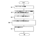
まず、区分サイズが設定されている場合の電源投入時処理である区分サイズ識別処理について説明する。図14は、本実施の形態に係る区分サイズ識別処理の動作の一例を示すフローチャートである。まず、処理S81,S82,S83は、実施の形態6と同様である。次に、MPU8は、システム領域から区分サイズを含む区分情報を読み出し(S86)、読み出した情報に基づいて各区分の区分サイズなどの設定を行い(S87)、このフローは終了する。 First, a description will be given of a partition size identification process that is a power-on process when a partition size is set. FIG. 14 is a flowchart showing an example of the operation of the segment size identification process according to the present embodiment. First, processes S81, S82, and S83 are the same as those in the sixth embodiment. Next, the MPU 8 reads the partition information including the partition size from the system area (S86), sets the partition size of each partition based on the read information (S87), and this flow ends.
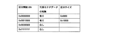
ここで、ディスク媒体15上のシステム領域に保存される区分情報について説明する。図15は、本実施の形態に係る区分情報の一例を示す表である。区分情報は、区分毎に、区分開始LBA、冗長セクタデータの有無、区分サイズを持つ。この例の場合、LBA(0x00000000)〜LBA(0x0000ffff)の領域は、区分サイズが0x0800セクタずつとなる区分に割り当てられ、各区分には冗長セクタが割り当てられる。また、LBA(0x00010000)〜LBA(0x0001ffff)の領域は、区分サイズが0x10000セクタずつとなる区分に割り当てられ、各区分には冗長セクタが割り当てられる。また、LBA(0x00020000)〜最終セクタの領域は、区分や冗長セクタが割り当てられない。
Here, the division information stored in the system area on the
上述した復元対象範囲の設定により、冗長セクタデータ更新処理における更新範囲は、冗長セクタデータがある領域に設定される。その他の動作は、実施の形態1と同様である。 By setting the restoration target range described above, the update range in the redundant sector data update process is set to an area where the redundant sector data is present. Other operations are the same as those in the first embodiment.
このような区分情報をシステム領域に保持しておくことにより、ハードディスク装置の用途毎、あるいはハードディスク装置のユーザ毎に区分や冗長セクタの割り当てを変更することができる。また、更新の多いユーザ領域、即ちエラーセクタの発生する確率の高い領域の冗長セクタデータの割合を多くすることにより、ハードディスク装置のリソースを効率的に使用することができるとともに、データを復元できる可能性が大幅に増大し、ハードディスク装置の信頼性を大幅に高めることができる。 By holding such partition information in the system area, the partition and the allocation of redundant sectors can be changed for each use of the hard disk device or for each user of the hard disk device. In addition, by increasing the proportion of redundant sector data in user areas that are frequently updated, that is, areas that have a high probability of generating error sectors, it is possible to efficiently use hard disk device resources and to restore data. And the reliability of the hard disk device can be greatly enhanced.
実施の形態8.
本実施の形態においては、各冗長セクタデータが有効か否かの情報を持つハードディスク装置について説明する。
Embodiment 8 FIG.
In the present embodiment, a hard disk device having information on whether each redundant sector data is valid will be described.
本実施の形態に係るハードディスク装置の構成は、実施の形態1と同様である。 The configuration of the hard disk device according to the present embodiment is the same as that of the first embodiment.
次に、各冗長セクタデータが有効であるか無効であるかを示す冗長セクタデータテーブルについて説明する。 Next, a redundant sector data table indicating whether each redundant sector data is valid or invalid will be described.
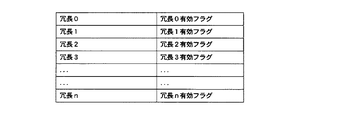
冗長セクタデータテーブルは、MPU8により生成され、不揮発性メモリ10に格納される。図16は、本実施の形態に係る冗長セクタデータテーブルのデータ構造の一例を示す表である。冗長セクタデータテーブルは、冗長セクタデータ毎に、対応する冗長セクタデータ番号(区分番号)と、その冗長セクタデータが有効であるか無効であるかを示す有効フラグとを持つ。MPU8は、冗長セクタデータの更新時に、この冗長セクタデータテーブルを参照することにより、無効な冗長セクタデータのみを更新することができ、効率的に冗長セクタデータの更新を行うことができる。 The redundant sector data table is generated by the MPU 8 and stored in the nonvolatile memory 10. FIG. 16 is a table showing an example of the data structure of the redundant sector data table according to the present embodiment. The redundant sector data table has, for each redundant sector data, a corresponding redundant sector data number (partition number) and a valid flag indicating whether the redundant sector data is valid or invalid. The MPU 8 can update only invalid redundant sector data by referring to this redundant sector data table when updating redundant sector data, and can efficiently update redundant sector data.
この冗長セクタデータテーブルの更新は、上位装置からのコマンドを受領していないタイミングで行うことが望ましい。 It is desirable to update the redundant sector data table at a timing when a command from the host device is not received.
次に、本実施の形態に係るハードディスク装置の動作について説明する。 Next, the operation of the hard disk device according to the present embodiment will be described.
冗長セクタデータ更新処理は、実施の形態1と同様であるが、処理S12の代わりに、冗長セクタデータテーブルから有効フラグが無効を示す区分を検索し、検索された区分を更新範囲として設定する。その他の処理は、実施の形態1と同様である。 The redundant sector data update process is the same as that in the first embodiment, but instead of the process S12, a segment in which the valid flag is invalid is retrieved from the redundant sector data table, and the retrieved segment is set as an update range. Other processes are the same as those in the first embodiment.
次に、上位装置からコマンドを受領する場合の処理であるコマンド受領処理について説明する。 Next, a command receiving process, which is a process when receiving a command from the host device, will be described.
図17は、本実施の形態に係るコマンド受領処理の動作の一例を示すフローチャートである。まず、MPU8は、上位装置からのコマンドを受領したか否かの判断を行い、受領していなければ(S51,N)、処理S51へ戻り、受領していれば(S51,Y)、次の処理へ移行する。次に、MPU8は、コマンドがデータの書き込みであるか否かの判断を行い、書き込みでなければ(S52,N)、処理S54へ移行し、書き込みであれば(S52,Y)、次の処理へ移行する。次に、MPU8は、フラグクリア処理を行う(S53)。次に、MPU8は、コマンドに従う通常の処理であるコマンド処理を行い(S54)。このフローは終了する。 FIG. 17 is a flowchart showing an example of the operation of command reception processing according to the present embodiment. First, the MPU 8 determines whether or not a command from the host device has been received. If it has not been received (S51, N), the process returns to step S51. If it has been received (S51, Y), Transition to processing. Next, the MPU 8 determines whether or not the command is data writing. If it is not writing (S52, N), the process proceeds to step S54. If it is writing (S52, Y), the next processing is performed. Migrate to Next, the MPU 8 performs a flag clear process (S53). Next, the MPU 8 performs command processing which is normal processing according to the command (S54). This flow ends.
次に、有効フラグをクリア(無効に)するフラグクリア処理について説明する。 Next, a flag clear process for clearing (invalidating) the valid flag will be described.
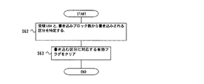
図18は、本実施の形態に係るフラグクリア処理の動作の一例を示すフローチャートである。まず、MPU8は、受領したLBAと書き込みサイズから書き込みの対象の区分である書き込み対象区分を特定する(S62)。例えば、全ての区分のサイズが一定である場合、MPU8は、(受領LBA÷区分サイズ)を書き込み対象区分の開始区分とし、((受領LBA+書き込みサイズ)÷区分サイズ)を書き込み対象区分の終了区分とする。区分サイズが一定でない場合、区分サイズで場合分けを行う。次に、MPU8は、書き込み対象区分に対応する有効フラグをクリアし(S63)、このフローは終了する。 FIG. 18 is a flowchart showing an example of the operation of the flag clear process according to the present embodiment. First, the MPU 8 specifies a write target section, which is a write target section, from the received LBA and write size (S62). For example, when the sizes of all the sections are constant, the MPU 8 sets (reception LBA ÷ partition size) as the start section of the write target section and ((reception LBA + write size) ÷ partition size) as the end section of the write target section. And If the segment size is not constant, the segmentation is performed according to the segment size. Next, the MPU 8 clears the valid flag corresponding to the write target section (S63), and this flow ends.
もし、データの書き込みの後にフラグクリア処理を行うとすると、書き込みとフラグクリア処理の間に不測の事態が発生して有効フラグが残ったままになった場合、誤ったエラーセクタデータ復元処理が行われる。そのため、本実施の形態において、フラグクリア処理は、データの書き込みの前に行われる。 If the flag clear process is performed after the data is written, if an unforeseen situation occurs between the write and the flag clear process and the valid flag remains, an erroneous error sector data recovery process is performed. Is called. Therefore, in the present embodiment, the flag clear process is performed before data writing.
次に、有効フラグをセット(有効に)するフラグセット処理について説明する。 Next, a flag setting process for setting (validating) a valid flag will be described.
MPU8は、単一冗長セクタデータ書き込み処理の後に、フラグセット処理を行う。ここで、MPU8は、冗長セクタデータテーブルにおいて、単一冗長セクタデータ書き込み処理により書き込まれた冗長セクタデータに対応する有効フラグをセットする。 The MPU 8 performs a flag set process after the single redundant sector data write process. Here, the MPU 8 sets a valid flag corresponding to the redundant sector data written by the single redundant sector data writing process in the redundant sector data table.
もし、単一冗長セクタデータ書き込み処理の前にフラグセット処理を行うとすると、冗長セクタデータが書き込まれていない状態で有効フラグだけセットされた場合、誤ったエラーセクタデータ復元処理が行われる。 If the flag setting process is performed before the single redundant sector data writing process, if only the valid flag is set in a state where the redundant sector data is not written, an erroneous error sector data restoring process is performed.
次に、本実施の形態に係るエラーセクタデータ復元処理について説明する。 Next, error sector data restoration processing according to the present embodiment will be described.
図19は、本実施の形態に係るエラーセクタデータ復元処理の動作の一例を示すフローチャートである。まず、MPU8は、検出したエラーセクタのLBAからエラーセクタが属する区分を特定し、冗長セクタデータテーブルを参照してその区分に対応する有効フラグを取得する(S41)。次に、MPU8は、取得した有効フラグが有効を示すか否かの判断を行い、無効を示す場合(S42,N)、このフローは終了し、有効を示す場合(S42,Y)、次の処理へ移行する。その後の処理S44,S45,S46,S47,S48は、実施の形態1のエラーセクタデータ復元処理と同様である。 FIG. 19 is a flowchart showing an example of operation of error sector data restoration processing according to the present embodiment. First, the MPU 8 specifies a section to which the error sector belongs from the LBA of the detected error sector, and acquires a valid flag corresponding to the section by referring to the redundant sector data table (S41). Next, the MPU 8 determines whether or not the acquired validity flag indicates validity. When the validity flag indicates invalidity (S42, N), this flow ends, and when the validity flag indicates validity (S42, Y), Transition to processing. The subsequent processes S44, S45, S46, S47, and S48 are the same as the error sector data restoration process of the first embodiment.
ハードディスク装置の電源が切られた後、冗長セクタデータテーブルが保持されていないと、次回の電源投入直後にエラーセクタが検出された場合にエラーセクタデータ復元処理を行うことができない。そこで、本実施の形態においては、冗長セクタデータテーブルは、不揮発性メモリ10に保存されるとした。 If the redundant sector data table is not retained after the hard disk device is turned off, the error sector data restoration process cannot be performed when an error sector is detected immediately after the next power-on. Therefore, in the present embodiment, the redundant sector data table is stored in the nonvolatile memory 10.
なお、ハードディスク装置が上位装置からFlush Cacheコマンドやヘッドを退避させるコマンドを受領したタイミングで、冗長セクタデータテーブルが更新され、ディスク媒体15に書き込まれるようにしても良い。ハードディスク装置は、一般的にライトキャッシュ機能を使用しているため、電源が切られる前、データバッファ4(キャッシュ)に保持されている上位装置からの書き込みデータがディスク媒体15に書き込まれる。Flush Cacheコマンドは、この書き込みを強制的に行わせるものであり、ハードディスク装置の電源OFFの前に上位装置から発行される。従って、このタイミングを利用して、MPU8は、冗長セクタデータテーブルの更新とディスク媒体15への書き込みを行う。
Note that the redundant sector data table may be updated and written to the
本実施の形態によれば、更新の必要な冗長セクタデータのみを更新することができるため、冗長セクタデータの更新の負荷を低減することができる。従って、ハードディスク装置の性能低下を抑えつつ、迅速に冗長セクタデータを更新することができる。また、エラーセクタが検出された場合に、エラーセクタに対応する冗長セクタデータが生成されている確率を高めることができる。 According to the present embodiment, only redundant sector data that needs to be updated can be updated, so that the load of updating redundant sector data can be reduced. Therefore, the redundant sector data can be updated quickly while suppressing the performance degradation of the hard disk device. In addition, when an error sector is detected, the probability that redundant sector data corresponding to the error sector is generated can be increased.
ここで、全ての区分サイズを小さくすると、エラーセクタに対する冗長セクタデータが有効である可能性が高くなるが、ハードディスク装置内部のメモリ9やディスク媒体15上のシステム領域などのリソースの消費が増大する。そこで、実施の形態7のように、区分毎に区分サイズを変えることにより、リソースの消費を抑えつつ、ハードディスク装置の信頼性を高めることができる。
Here, if all the partition sizes are reduced, the possibility that the redundant sector data for the error sector is effective increases, but the consumption of resources such as the memory 9 in the hard disk device and the system area on the
実施の形態9.
本実施の形態においては、区分情報を動的に変更するハードディスク装置について説明する。
Embodiment 9 FIG.
In the present embodiment, a hard disk device that dynamically changes classification information will be described.
本実施の形態に係るハードディスク装置の構成は、実施の形態1と同様である。 The configuration of the hard disk device according to the present embodiment is the same as that of the first embodiment.
次に、本実施の形態に係るハードディスク装置の動作について説明する。 Next, the operation of the hard disk device according to the present embodiment will be described.
冗長セクタデータ更新処理、冗長セクタデータ生成処理、単一冗長セクタデータ書き込み処理、ユーザデータ読み出し処理、ディスク媒体走査処理は、実施の形態1と同様である。また、実施の形態8と同様、冗長セクタデータテーブルが不揮発性メモリ10に格納される。また、実施の形態2と同様、セクタ配置は、全ての通常セクタが連続して配置された後に、全ての冗長セクタが連続して配置される。また、実施の形態7と同様、ディスク媒体15上のシステム領域に区分情報が保存される。
The redundant sector data update process, redundant sector data generation process, single redundant sector data write process, user data read process, and disk medium scanning process are the same as those in the first embodiment. Further, as in the eighth embodiment, the redundant sector data table is stored in the nonvolatile memory 10. Further, as in the second embodiment, in the sector arrangement, after all the normal sectors are continuously arranged, all the redundant sectors are continuously arranged. In addition, the classification information is stored in the system area on the
次に、区分情報を動的に変更する区分情報変更処理について説明する。 Next, the classification information changing process for dynamically changing the classification information will be described.
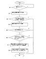
図20は、本実施の形態に係る区分情報変更処理の動作の一例を示すフローチャートである。まず、MPU8は、上位装置から書き込みコマンドを受領したか否かの判断を行い、受領していない場合(S91,N)、処理S91へ戻り、受領した場合(S91,Y)、次の処理へ移行する。次に、MPU8は、書き込み範囲の最終LBAを計算する(S92)。次に、MPU8は、今までに書き込みが無かった領域への書き込みか否かの判断を行い、書き込みが無かった領域への書き込みで無い場合(S93,N)、このフローは終了し、書き込みが無かった領域への書き込みである場合(S93,Y)、次の処理へ移行する。 FIG. 20 is a flowchart showing an example of the operation of the classification information change process according to the present embodiment. First, the MPU 8 determines whether or not a write command has been received from the host device. If it has not been received (S91, N), the process returns to the process S91. If it has been received (S91, Y), the process proceeds to the next process. Transition. Next, the MPU 8 calculates the final LBA of the write range (S92). Next, the MPU 8 determines whether or not the writing has been performed in the area that has not been written so far. If the writing has not been performed in the area that has not been written (S93, N), this flow ends and the writing is completed. If the writing is in the area that did not exist (S93, Y), the process proceeds to the next process.
次に、MPU8は、書き込み範囲の最終LBAを書き込み最大LBAとして記憶する(S94)。次に、MPU8は、所定の時間間隔が経過したか否かの判断を行い、経過していない場合(S95,N)、このフローは終了し、経過した場合(S95,Y)、次の処理へ移行する。次に、MPU8は、書き込み最大LBAが冗長セクタを割り当てている区分よりも大きいか否かの判断を行い、大きくない場合(S96,N)、このフローは終了し、大きい場合(S96,Y)、次の処理へ移行する。次に、MPU8は、書き込み最大LBAを含む区分まで、冗長セクタを割り当てて使用するように区分情報の変更を行う(S97)。次に、MPU8は、冗長セクタ有効テーブルの初期化を行い、全ての冗長セクタデータを一旦無効にし(S98)、このフローは終了する。 Next, the MPU 8 stores the final LBA of the write range as the write maximum LBA (S94). Next, the MPU 8 determines whether or not a predetermined time interval has elapsed. If it has not elapsed (S95, N), this flow ends, and if it has elapsed (S95, Y), the next process Migrate to Next, the MPU 8 determines whether or not the maximum write LBA is larger than the section to which the redundant sector is allocated. If not larger (S96, N), this flow ends, and if larger (S96, Y). Then, the process proceeds to the next process. Next, the MPU 8 changes the partition information so that redundant sectors are allocated and used up to the partition including the maximum write LBA (S97). Next, the MPU 8 initializes the redundant sector validity table, temporarily invalidates all redundant sector data (S98), and this flow ends.
ハードディスク装置において使用開始からディスク容量の全体を使用するようになるまでの期間は長い。もし、使用開始時に全ての区分情報が設定されるとすると、未使用のユーザ領域に対応した冗長セクタの領域は、しばらく使用されない。本実施の形態によれば、動的に区分情報を変更することにより、未使用の冗長セクタの領域を減らすことができる。例えば、ユーザ領域全体に亘って0x10000セクタ毎に区分が構成されている場合、ユーザ領域の半分未満の領域だけが使用されている状態では区分サイズを0x08000にすることにより、冗長セクタの領域を有効に利用することができる。 The period from the start of use in the hard disk device until the entire disk capacity is used is long. If all the division information is set at the start of use, the redundant sector area corresponding to the unused user area is not used for a while. According to the present embodiment, the area of unused redundant sectors can be reduced by dynamically changing the partition information. For example, when a partition is configured for each 0x10000 sector over the entire user area, the redundant sector area is enabled by setting the partition size to 0x08000 when only less than half of the user area is used. Can be used.
なお、第1ブロックは、実施の形態における通常セクタに対応する。また、第2ブロックは、実施の形態における区分に対応する。また、第3ブロックは、実施の形態における冗長セクタに対応する。また、記憶媒体は、実施の形態におけるディスク媒体に対応する。また、更新対象は、実施の形態における更新範囲に対応する。また、演算データは、実施の形態における演算結果データに対応する。また、演算部は、実施の形態における冗長演算部に対応する。また、書き込み部及び読み出し部は、実施の形態におけるMPU、データバッファ、バッファ制御部、フォーマット制御部に対応する。また、演算ステップは、実施の形態における処理S13に対応する。また、書き込みステップは、実施の形態における処理S14または処理S19に対応する。 The first block corresponds to the normal sector in the embodiment. The second block corresponds to the division in the embodiment. The third block corresponds to the redundant sector in the embodiment. The storage medium corresponds to the disk medium in the embodiment. The update target corresponds to the update range in the embodiment. Further, the calculation data corresponds to the calculation result data in the embodiment. The calculation unit corresponds to the redundant calculation unit in the embodiment. The writing unit and the reading unit correspond to the MPU, the data buffer, the buffer control unit, and the format control unit in the embodiment. The calculation step corresponds to step S13 in the embodiment. The writing step corresponds to the process S14 or the process S19 in the embodiment.
また、管理情報記憶部は、実施の形態における冗長セクタデータテーブルに対応する。また、管理情報記憶ステップは、実施の形態におけるフラグセット処理及びフラグクリア処理に対応する。また、読み出しステップは、実施の形態におけるエラーセクタデータ復元処理に対応する。 The management information storage unit corresponds to the redundant sector data table in the embodiment. The management information storing step corresponds to the flag setting process and the flag clearing process in the embodiment. The reading step corresponds to the error sector data restoration process in the embodiment.
また、本実施の形態に係るMPU8及び冗長演算部21は、記憶装置に容易に適用することができ、記憶装置の性能をより高めることができる。ここで、記憶装置には、例えば磁気ディスク装置、光ディスク装置、光磁気ディスク装置等が含まれ得る。
In addition, the MPU 8 and the
(付記1) 所定のデータ長の第1ブロックを単位としてデータが配置され、且つ複数の前記第1ブロックで構成される第2ブロックを単位として前記第1ブロックが配置され、且つ前記第2ブロックに対応して前記第1ブロック長を持つ第3ブロックが配置される記憶媒体に対して少なくとも書き込み処理を行う記憶装置に用いられる記憶データ処理装置において、
前記第2ブロック毎に、該第2ブロックに対応する第3ブロックが有効か無効かの情報を含む管理情報を記憶する管理情報記憶部と、
前記管理情報記憶部に記憶された管理情報において、更新対象として指定された第2ブロックに対応する第3ブロックが無効である場合、前記更新対象中の全ての第1ブロックのデータについてビット位置毎の演算を行い、該演算の結果を演算データとして出力する演算部と、
前記演算部により出力された演算データを、前記更新対象に対応付けられた第3ブロックへ書き込み、前記管理情報記憶部に記憶された管理情報において該第3ブロックを有効とする書き込み部と
を備える記憶データ処理装置。
(付記2) 付記1に記載の記憶データ処理装置において、
前記演算部は、前記演算データを初期化し、前記更新対象中の各々の第1ブロックのデータを順次、前記演算の入力データとし、該入力データと前記演算データについてビット位置毎の演算を行い、該演算の結果を新たな演算データとして記憶し、該演算と該記憶を全ての前記入力データについて繰り返し、前記演算データを出力することを特徴とする記憶データ処理装置。
(付記3) 付記1または付記2に記載の記憶データ処理装置において、
更に、読み出し対象として指定された第1ブロックからデータを読み出し、該データの読み出しに失敗した場合、前記読み出しに失敗した第1ブロックをエラーブロックとし、前記管理情報記憶部に記憶された管理情報において前記読み出し対象を含む第2ブロックに対応する第3ブロックが有効である場合、該第2ブロック中の該エラーブロック以外の全ての第1ブロックのデータである正常データを読み出し、該第2ブロックに対応する第3ブロックのデータである冗長データを読み出す読み出し部を備え、
前記演算部は更に、前記正常データと前記冗長データについてビット位置毎の演算を行い、該演算の結果を前記エラーブロックのデータとして出力することを特徴とする記憶データ処理装置。
(付記4) 付記3に記載の記憶データ処理装置において、
前記演算部は、前記演算データを初期化し、各々の前記正常データと前記冗長データを順次、前記演算の入力データとし、該入力データと前記演算データについてビット位置毎の演算を行い、該演算の結果を新たな演算データとして記憶し、該演算と該記憶を全ての前記入力データについて繰り返し、前記演算データを出力することを特徴とする記憶データ処理装置。
(付記5) 付記1乃至付記4のいずれかに記載の記憶データ処理装置において、
前記書き込み部は、外部装置からのデータ書き込み指示を受けた場合、前記データ書き込み命令によるデータ書き込み対象を含む第2ブロックに対応する第3ブロックについて、前記管理情報記憶部に記憶された管理情報において該第3ブロックを有効とすることを特徴とする記憶データ処理装置。
(付記6) 付記1乃至付記5のいずれかに記載の記憶データ処理装置において、
前記演算部は、外部装置からのデータ読み出し指示またはデータ書き込み指示による処理を行っていないときに、前記管理情報記憶部に記憶された管理情報において無効である第3ブロックに対応する第2ブロックについて前記演算を行うことを特徴とする記憶データ処理装置。
(付記7) 付記1乃至付記6のいずれかに記載の記憶データ処理装置において、
前記管理情報記憶部は、不揮発性メモリであることを特徴とする記憶データ処理装置。
(付記8) 付記1乃至付記6のいずれかに記載の記憶データ処理装置において、
前記管理情報記憶部は、外部装置からライトキャッシュデータを前記記憶媒体上に書き込む指示、またはヘッドを退避させる指示を受領した場合、前記管理情報を前記記憶媒体に書き込むことを特徴とする記憶データ処理装置。
(付記9) 付記1乃至付記8のいずれかに記載の記憶データ処理装置において、
前記管理情報は、前記第2ブロック毎に、該第2ブロックに含まれる複数の第1ブロックの指定を含むことを特徴とする記憶データ処理装置。
(付記10) 付記1乃至付記9のいずれかに記載の記憶データ処理装置において、
前記管理情報は、前記第2ブロック毎に、該第2ブロックに含まれる複数の第1ブロックの指定を含み、
前記書き込み部は、前記管理情報に基づいて前記第2ブロックを前記記憶媒体に配置することを特徴とする記憶データ処理装置。
(付記11) 付記10に記載の記憶データ処理装置において、
前記管理情報記憶部は、外部装置から各々の第2ブロックへのアクセス頻度に基づいて第2ブロックに含まれる複数の第1ブロックの数を決定し、前記管理情報に含めることを特徴とする記憶データ処理装置。
(付記12) 付記1乃至付記11のいずれかに記載の記憶データ処理装置において、
前記演算部による演算は、順次演算を行う順序を変えても演算結果が変わらない演算であることを特徴とする記憶データ処理装置。
(付記13) 付記12に記載の記憶データ処理装置において、
前記演算部による演算は、排他的論理和であることを特徴とする記憶データ処理装置。
(付記14) 付記1乃至付記13のいずれかに記載の記憶データ処理装置において、
前記第1ブロックは、少なくとも1つのセクタであり、前記第3ブロックは、前記第1ブロック長を持ち、前記演算データは、前記第1ブロック長を持つことを特徴とする記憶データ処理装置。
(付記15) 記憶装置における記憶データ処理をコンピュータに実行させる記憶データ処理プログラムにおいて、
所定のデータ長の第1ブロックを単位としてデータが配置され、且つ複数の前記第1ブロックで構成される第2ブロックを単位として前記第1ブロックが配置され、且つ前記第2ブロックに対応して前記第1ブロック長を持つ第3ブロックが配置される記憶媒体について、前記第2ブロック毎に、該第2ブロックに対応する第3ブロックが有効か無効かの情報を含む管理情報を記憶する管理情報記憶ステップと、
前記管理情報記憶ステップにより記憶された管理情報において、更新対象として指定された第2ブロックに対応する第3ブロックが無効である場合、前記更新対象中の全ての第1ブロックのデータについてビット位置毎の演算を行い、該演算の結果を演算データとして出力する演算ステップと、
前記演算ステップにより出力された演算データを、前記更新対象に対応付けられた第3ブロックへ書き込み、前記管理情報記憶ステップにより記憶された管理情報において該第3ブロックを有効とする書き込みステップと
をコンピュータに実行させる記憶データ処理プログラム。
(付記16) 所定のデータ長の第1ブロックを単位としてデータが配置され、且つ複数の前記第1ブロックで構成される第2ブロックを単位として前記第1ブロックが配置され、且つ前記第2ブロックに対応して前記第1ブロック長を持つ第3ブロックが配置される記憶媒体に対して少なくとも書き込み処理を行う記憶装置において、
前記第2ブロック毎に、該第2ブロックに対応する第3ブロックが有効か無効かの情報を含む管理情報を記憶する管理情報記憶部と、
前記管理情報記憶部に記憶された管理情報において、更新対象として指定された第2ブロックに対応する第3ブロックが無効である場合、前記更新対象中の全ての第1ブロックのデータについてビット位置毎の演算を行い、該演算の結果を演算データとして出力する演算部と、
前記演算部により出力された演算データを、前記更新対象に対応付けられた第3ブロックへ書き込み、前記管理情報記憶部に記憶された管理情報において該第3ブロックを有効とする書き込み部と
を備える記憶装置。
(付記17) 付記16に記載の記憶装置において、
前記演算部は、前記演算データを初期化し、前記更新対象中の各々の第1ブロックのデータを順次、前記演算の入力データとし、該入力データと前記演算データについてビット位置毎の演算を行い、該演算の結果を新たな演算データとして記憶し、該演算と該記憶を全ての前記入力データについて繰り返し、前記演算データを出力することを特徴とする記憶装置。
(付記18) 付記16または付記17に記載の記憶装置において、
更に、読み出し対象として指定された第1ブロックからデータを読み出し、該データの読み出しに失敗した場合、前記読み出しに失敗した第1ブロックをエラーブロックとし、前記管理情報記憶部に記憶された管理情報において前記読み出し対象を含む第2ブロックに対応する第3ブロックが有効である場合、該第2ブロック中の該エラーブロック以外の全ての第1ブロックのデータである正常データを読み出し、該第2ブロックに対応する第3ブロックのデータである冗長データを読み出す読み出し部を備え、
前記演算部は更に、前記正常データと前記冗長データについてビット位置毎の演算を行い、該演算の結果を前記エラーブロックのデータとして出力することを特徴とする記憶装置。
(付記19) 付記18に記載の記憶装置において、
前記演算部は、前記演算データを初期化し、各々の前記正常データと前記冗長データを順次、前記演算の入力データとし、該入力データと前記演算データについてビット位置毎の演算を行い、該演算の結果を新たな演算データとして記憶し、該演算と該記憶を全ての前記入力データについて繰り返し、前記演算データを出力することを特徴とする記憶装置。
(付記20) 付記16乃至付記19のいずれかに記載の記憶装置において、
前記書き込み部は、外部装置からのデータ書き込み指示を受けた場合、前記データ書き込み命令によるデータ書き込み対象を含む第2ブロックに対応する第3ブロックについて、前記管理情報記憶部に記憶された管理情報において該第3ブロックを有効とすることを特徴とする記憶装置。
(Supplementary Note 1) Data is arranged in units of a first block having a predetermined data length, and the first block is arranged in units of a second block composed of a plurality of the first blocks, and the second block In a storage data processing device used for a storage device that performs at least a writing process on a storage medium in which a third block having the first block length is arranged corresponding to
A management information storage unit that stores management information including information on whether the third block corresponding to the second block is valid or invalid for each second block;
In the management information stored in the management information storage unit, when the third block corresponding to the second block designated as the update target is invalid, the data of all the first blocks in the update target for each bit position A calculation unit that performs the calculation of and outputs the result of the calculation as calculation data;
A calculation unit that writes the calculation data output by the calculation unit to the third block associated with the update target and that validates the third block in the management information stored in the management information storage unit; Stored data processing device.
(Supplementary Note 2) In the storage data processing apparatus according to
The calculation unit initializes the calculation data, sequentially sets the data of each first block being updated as input data for the calculation, performs calculation for each bit position on the input data and the calculation data, A stored data processing apparatus that stores the result of the calculation as new calculation data, repeats the calculation and the storage for all the input data, and outputs the calculation data.
(Supplementary Note 3) In the stored data processing apparatus according to
Further, when data is read from the first block designated as a read target and the data read fails, the first block that fails to be read is regarded as an error block, and the management information stored in the management information storage unit When the third block corresponding to the second block including the read target is valid, normal data that is data of all the first blocks other than the error block in the second block is read, and the second block is read. A reading unit that reads redundant data that is data of the corresponding third block is provided,
The stored data processing device, wherein the operation unit further performs an operation for each bit position on the normal data and the redundant data, and outputs a result of the operation as data of the error block.
(Supplementary Note 4) In the storage data processing apparatus according to
The calculation unit initializes the calculation data, sequentially sets the normal data and the redundant data as input data for the calculation, performs calculation for each bit position on the input data and the calculation data, A stored data processing apparatus that stores a result as new operation data, repeats the operation and the storage for all the input data, and outputs the operation data.
(Supplementary Note 5) In the stored data processing apparatus according to any one of
In the management information stored in the management information storage unit, when the writing unit receives a data writing instruction from an external device, the third block corresponding to the second block including the data writing target by the data writing command A stored data processing apparatus characterized by validating the third block.
(Supplementary Note 6) In the storage data processing device according to any one of
When the arithmetic unit does not perform the process according to the data read instruction or the data write instruction from the external device, the second block corresponding to the third block that is invalid in the management information stored in the management information storage unit A stored data processing apparatus that performs the calculation.
(Supplementary note 7) In the stored data processing apparatus according to any one of
The storage data processing device, wherein the management information storage unit is a nonvolatile memory.
(Supplementary Note 8) In the storage data processing apparatus according to any one of
The management information storage unit writes the management information to the storage medium when receiving an instruction to write write cache data on the storage medium or an instruction to retract the head from an external device. apparatus.
(Supplementary note 9) In the stored data processing apparatus according to any one of
The storage data processing apparatus, wherein the management information includes designation of a plurality of first blocks included in the second block for each of the second blocks.
(Supplementary Note 10) In the stored data processing apparatus according to any one of
The management information includes designation of a plurality of first blocks included in the second block for each second block;
The storage unit according to
(Supplementary Note 11) In the storage data processing apparatus according to Supplementary Note 10,
The management information storage unit determines the number of a plurality of first blocks included in the second block based on an access frequency from the external device to each of the second blocks, and includes the management information in the management information. Data processing device.
(Supplementary note 12) In the stored data processing device according to any one of
The stored data processing apparatus according to
(Supplementary note 13) In the storage data processing apparatus according to
The stored data processing apparatus, wherein the operation by the operation unit is exclusive OR.
(Supplementary Note 14) In the storage data processing apparatus according to any one of
The storage data processing apparatus, wherein the first block is at least one sector, the third block has the first block length, and the operation data has the first block length.
(Supplementary Note 15) In a storage data processing program for causing a computer to execute storage data processing in a storage device,
Data is arranged in units of a first block having a predetermined data length, and the first block is arranged in units of a second block composed of a plurality of the first blocks, and corresponding to the second block Management for storing management information including information on whether the third block corresponding to the second block is valid or invalid for each second block of the storage medium on which the third block having the first block length is arranged An information storage step;
In the management information stored in the management information storing step, when the third block corresponding to the second block designated as the update target is invalid, the data of all the first blocks in the update target is set for each bit position. A calculation step of performing the calculation of and outputting the result of the calculation as calculation data;
A calculation step of writing the calculation data output in the calculation step into a third block associated with the update target, and making the third block valid in the management information stored in the management information storage step; A stored data processing program to be executed by the program.
(Supplementary Note 16) Data is arranged in units of a first block having a predetermined data length, and the first block is arranged in units of a second block composed of a plurality of the first blocks, and the second block In a storage device that performs at least write processing on a storage medium in which the third block having the first block length corresponding to
A management information storage unit that stores management information including information on whether the third block corresponding to the second block is valid or invalid for each second block;
In the management information stored in the management information storage unit, when the third block corresponding to the second block designated as the update target is invalid, the data of all the first blocks in the update target for each bit position A calculation unit that performs the calculation of and outputs the result of the calculation as calculation data;
A calculation unit that writes the calculation data output by the calculation unit to the third block associated with the update target and that validates the third block in the management information stored in the management information storage unit; Storage device.
(Supplementary note 17) In the storage device according to
The calculation unit initializes the calculation data, sequentially sets the data of each first block being updated as input data for the calculation, performs calculation for each bit position on the input data and the calculation data, A storage device that stores the result of the calculation as new calculation data, repeats the calculation and the storage for all the input data, and outputs the calculation data.
(Supplementary Note 18) In the storage device according to
Further, when data is read from the first block designated as a read target and the data read fails, the first block that fails to be read is regarded as an error block, and the management information stored in the management information storage unit When the third block corresponding to the second block including the read target is valid, normal data that is data of all the first blocks other than the error block in the second block is read, and the second block is read. A reading unit that reads redundant data that is data of the corresponding third block is provided,
The storage unit further performs a calculation for each bit position on the normal data and the redundant data, and outputs a result of the calculation as data of the error block.
(Supplementary note 19) In the storage device according to supplementary note 18,
The calculation unit initializes the calculation data, sequentially sets each of the normal data and the redundant data as input data for the calculation, performs calculation for each bit position on the input data and the calculation data, A storage device that stores a result as new calculation data, repeats the calculation and the storage for all the input data, and outputs the calculation data.
(Supplementary note 20) In the storage device according to any one of
In the management information stored in the management information storage unit, when the writing unit receives a data writing instruction from an external device, the third block corresponding to the second block including the data writing target by the data writing command A storage device that makes the third block effective.
2 ホストIF制御部、3 データバッファ制御部、4 データバッファ、5 フォーマット制御部、6 リードチャネル、7 ヘッドIC、8 MPU、9 メモリ、10 不揮発性メモリ、11 サーボ制御部、12 VCM、13 SPM、14 ヘッド、15 ディスク媒体、16 コモンバス、21 冗長演算部、31 演算結果メモリ、32 XOR演算部。 2 Host IF control unit, 3 data buffer control unit, 4 data buffer, 5 format control unit, 6 read channel, 7 head IC, 8 MPU, 9 memory, 10 nonvolatile memory, 11 servo control unit, 12 VCM, 13 SPM , 14 heads, 15 disk media, 16 common buses, 21 redundant operation unit, 31 operation result memory, 32 XOR operation unit.
Claims (6)
前記第2ブロック毎に、該第2ブロックに対応する第3ブロックが有効か無効かの情報を含む管理情報を記憶する管理情報記憶部と、
前記管理情報記憶部に記憶された管理情報において、更新対象として指定された第2ブロックに対応する第3ブロックが無効である場合、前記更新対象中の全ての第1ブロックのデータについてビット位置毎の演算を行い、該演算の結果を演算データとして出力する演算部と、
前記演算部により出力された演算データを、前記更新対象に対応付けられた第3ブロックへ書き込み、前記管理情報記憶部に記憶された管理情報において該第3ブロックを有効とする書き込み部と
を備える記憶データ処理装置。 Data is arranged in units of a first block having a predetermined data length, and the first block is arranged in units of a second block composed of a plurality of the first blocks, and corresponding to the second block In a storage data processing device used for a storage device that performs at least a writing process on a storage medium in which a third block having the first block length is arranged,
A management information storage unit that stores management information including information on whether the third block corresponding to the second block is valid or invalid for each second block;
In the management information stored in the management information storage unit, when the third block corresponding to the second block designated as the update target is invalid, the data of all the first blocks in the update target for each bit position A calculation unit that performs the calculation of and outputs the result of the calculation as calculation data;
A calculation unit that writes the calculation data output by the calculation unit to the third block associated with the update target and that validates the third block in the management information stored in the management information storage unit; Stored data processing device.
前記演算部は、前記演算データを初期化し、前記更新対象中の各々の第1ブロックのデータを順次、前記演算の入力データとし、該入力データと前記演算データについてビット位置毎の演算を行い、該演算の結果を新たな演算データとして記憶し、該演算と該記憶を全ての前記入力データについて繰り返し、前記演算データを出力することを特徴とする記憶データ処理装置。 The stored data processing apparatus according to claim 1.
The calculation unit initializes the calculation data, sequentially sets the data of each first block being updated as input data for the calculation, performs calculation for each bit position on the input data and the calculation data, A stored data processing apparatus that stores the result of the calculation as new calculation data, repeats the calculation and the storage for all the input data, and outputs the calculation data.
更に、読み出し対象として指定された第1ブロックからデータを読み出し、該データの読み出しに失敗した場合、前記読み出しに失敗した第1ブロックをエラーブロックとし、前記管理情報記憶部に記憶された管理情報において前記読み出し対象を含む第2ブロックに対応する第3ブロックが有効である場合、該第2ブロック中の該エラーブロック以外の全ての第1ブロックのデータである正常データを読み出し、該第2ブロックに対応する第3ブロックのデータである冗長データを読み出す読み出し部を備え、
前記演算部は更に、前記正常データと前記冗長データについてビット位置毎の演算を行い、該演算の結果を前記エラーブロックのデータとして出力することを特徴とする記憶データ処理装置。 The storage data processing device according to claim 1 or 2,
Further, when data is read from the first block designated as a read target and the data read fails, the first block that fails to be read is regarded as an error block, and the management information stored in the management information storage unit When the third block corresponding to the second block including the read target is valid, normal data that is data of all the first blocks other than the error block in the second block is read, and the second block is read. A reading unit that reads redundant data that is data of the corresponding third block is provided,
The stored data processing device, wherein the operation unit further performs an operation for each bit position on the normal data and the redundant data, and outputs a result of the operation as data of the error block.
前記演算部は、前記演算データを初期化し、各々の前記正常データと前記冗長データを順次、前記演算の入力データとし、該入力データと前記演算データについてビット位置毎の演算を行い、該演算の結果を新たな演算データとして記憶し、該演算と該記憶を全ての前記入力データについて繰り返し、前記演算データを出力することを特徴とする記憶データ処理装置。 The stored data processing apparatus according to claim 3.
The calculation unit initializes the calculation data, sequentially sets each of the normal data and the redundant data as input data for the calculation, performs calculation for each bit position on the input data and the calculation data, A stored data processing apparatus that stores a result as new operation data, repeats the operation and the storage for all the input data, and outputs the operation data.
所定のデータ長の第1ブロックを単位としてデータが配置され、且つ複数の前記第1ブロックで構成される第2ブロックを単位として前記第1ブロックが配置され、且つ前記第2ブロックに対応して前記第1ブロック長を持つ第3ブロックが配置される記憶媒体について、前記第2ブロック毎に、該第2ブロックに対応する第3ブロックが有効か無効かの情報を含む管理情報を記憶する管理情報記憶ステップと、
前記管理情報記憶ステップにより記憶された管理情報において、更新対象として指定された第2ブロックに対応する第3ブロックが無効である場合、前記更新対象中の全ての第1ブロックのデータについてビット位置毎の演算を行い、該演算の結果を演算データとして出力する演算ステップと、
前記演算ステップにより出力された演算データを、前記更新対象に対応付けられた第3ブロックへ書き込み、前記管理情報記憶ステップにより記憶された管理情報において該第3ブロックを有効とする書き込みステップと
をコンピュータに実行させる記憶データ処理プログラム。 In a storage data processing program for causing a computer to execute storage data processing in a storage device,
Data is arranged in units of a first block having a predetermined data length, and the first block is arranged in units of a second block composed of a plurality of the first blocks, and corresponding to the second block Management for storing management information including information on whether the third block corresponding to the second block is valid or invalid for each second block of the storage medium on which the third block having the first block length is arranged An information storage step;
In the management information stored in the management information storing step, when the third block corresponding to the second block designated as the update target is invalid, the data of all the first blocks in the update target is set for each bit position. A calculation step of performing the calculation of and outputting the result of the calculation as calculation data;
A calculation step of writing the calculation data output in the calculation step into a third block associated with the update target, and making the third block valid in the management information stored in the management information storage step; A stored data processing program to be executed by the program.
前記第2ブロック毎に、該第2ブロックに対応する第3ブロックが有効か無効かの情報を含む管理情報を記憶する管理情報記憶部と、
前記管理情報記憶部に記憶された管理情報において、更新対象として指定された第2ブロックに対応する第3ブロックが無効である場合、前記更新対象中の全ての第1ブロックのデータについてビット位置毎の演算を行い、該演算の結果を演算データとして出力する演算部と、
前記演算部により出力された演算データを、前記更新対象に対応付けられた第3ブロックへ書き込み、前記管理情報記憶部に記憶された管理情報において該第3ブロックを有効とする書き込み部と
を備える記憶装置。 Data is arranged in units of a first block having a predetermined data length, and the first block is arranged in units of a second block composed of a plurality of the first blocks, and corresponding to the second block In a storage device that performs at least a writing process on a storage medium in which a third block having the first block length is arranged,
A management information storage unit that stores management information including information on whether the third block corresponding to the second block is valid or invalid for each second block;
In the management information stored in the management information storage unit, when the third block corresponding to the second block designated as the update target is invalid, the data of all the first blocks in the update target for each bit position A calculation unit that performs the calculation of and outputs the result of the calculation as calculation data;
A calculation unit that writes the calculation data output by the calculation unit to the third block associated with the update target and that validates the third block in the management information stored in the management information storage unit; Storage device.
Priority Applications (2)
| Application Number | Priority Date | Filing Date | Title |
|---|---|---|---|
| JP2006256752A JP2008077458A (en) | 2006-09-22 | 2006-09-22 | Storage data processing device, storage device, storage data processing program |
| US11/650,724 US7627725B2 (en) | 2006-09-22 | 2007-01-08 | Stored data processing apparatus, storage apparatus, and stored data processing program |
Applications Claiming Priority (1)
| Application Number | Priority Date | Filing Date | Title |
|---|---|---|---|
| JP2006256752A JP2008077458A (en) | 2006-09-22 | 2006-09-22 | Storage data processing device, storage device, storage data processing program |
Publications (1)
| Publication Number | Publication Date |
|---|---|
| JP2008077458A true JP2008077458A (en) | 2008-04-03 |
Family
ID=39226396
Family Applications (1)
| Application Number | Title | Priority Date | Filing Date |
|---|---|---|---|
| JP2006256752A Pending JP2008077458A (en) | 2006-09-22 | 2006-09-22 | Storage data processing device, storage device, storage data processing program |
Country Status (2)
| Country | Link |
|---|---|
| US (1) | US7627725B2 (en) |
| JP (1) | JP2008077458A (en) |
Cited By (2)
| Publication number | Priority date | Publication date | Assignee | Title |
|---|---|---|---|---|
| JP2010146625A (en) * | 2008-12-17 | 2010-07-01 | Toshiba Storage Device Corp | Storage device and storage device control method |
| JP2010267333A (en) * | 2009-05-15 | 2010-11-25 | Nippon Hoso Kyokai <Nhk> | Hard disk device with parity function |
Families Citing this family (6)
| Publication number | Priority date | Publication date | Assignee | Title |
|---|---|---|---|---|
| GB2446183B (en) * | 2007-01-31 | 2011-07-20 | Hewlett Packard Development Co | Method and apparatus for controlling motion of storage media |
| JP5381519B2 (en) * | 2009-09-01 | 2014-01-08 | 富士通株式会社 | A storage control device, a storage system, and an access method for detecting an erroneous calculation of a write position on a disk. |
| CN104765658B (en) * | 2015-04-30 | 2017-10-13 | 四川效率源信息安全技术股份有限公司 | Western number hard disc physical problem causes the data reconstruction method of parameter identification mistake |
| JP6845021B2 (en) * | 2017-01-12 | 2021-03-17 | 株式会社東芝 | Electronic devices, IC cards and information processing systems |
| JP2023142223A (en) | 2022-03-24 | 2023-10-05 | 株式会社東芝 | magnetic disk device |
| JP2024137183A (en) | 2023-03-24 | 2024-10-07 | 株式会社東芝 | Magnetic disk device and parity management method |
Citations (7)
| Publication number | Priority date | Publication date | Assignee | Title |
|---|---|---|---|---|
| JPH0535416A (en) * | 1991-07-26 | 1993-02-12 | Nec Corp | File controller |
| JPH07141123A (en) * | 1993-09-27 | 1995-06-02 | Hitachi Ltd | Array type disk system and control method of array type disk system |
| JPH08124318A (en) * | 1994-10-24 | 1996-05-17 | Sony Corp | Data recording method and device, data reproducing method and device, data recording and reproducing method, and recording medium |
| JPH09330180A (en) * | 1996-06-10 | 1997-12-22 | Hitachi Ltd | Disk array device for computer system |
| JP2000207134A (en) * | 1999-01-08 | 2000-07-28 | Nec Corp | Disk array device and control method |
| JP2002312130A (en) * | 2001-03-14 | 2002-10-25 | Hewlett Packard Co <Hp> | Improved stripe-based processing method |
| JP2003167689A (en) * | 2001-11-30 | 2003-06-13 | Toshiba Corp | Disk array device and parity processing method in the device |
Family Cites Families (5)
| Publication number | Priority date | Publication date | Assignee | Title |
|---|---|---|---|---|
| JPH06332623A (en) | 1993-05-24 | 1994-12-02 | Mitsubishi Electric Corp | Array type recorder and recorder |
| JPH1186465A (en) | 1997-09-01 | 1999-03-30 | Victor Co Of Japan Ltd | Signal processor |
| JP3272308B2 (en) | 1998-09-25 | 2002-04-08 | インターナショナル・ビジネス・マシーンズ・コーポレーション | Error correction system, error correction method, and data storage system having error correction function |
| JP2003346432A (en) | 2002-05-22 | 2003-12-05 | Internatl Business Mach Corp <Ibm> | Data storage device and data processing method |
| JP2006277395A (en) * | 2005-03-29 | 2006-10-12 | Matsushita Electric Ind Co Ltd | Information processing apparatus and information processing method |
-
2006
- 2006-09-22 JP JP2006256752A patent/JP2008077458A/en active Pending
-
2007
- 2007-01-08 US US11/650,724 patent/US7627725B2/en not_active Expired - Fee Related
Patent Citations (7)
| Publication number | Priority date | Publication date | Assignee | Title |
|---|---|---|---|---|
| JPH0535416A (en) * | 1991-07-26 | 1993-02-12 | Nec Corp | File controller |
| JPH07141123A (en) * | 1993-09-27 | 1995-06-02 | Hitachi Ltd | Array type disk system and control method of array type disk system |
| JPH08124318A (en) * | 1994-10-24 | 1996-05-17 | Sony Corp | Data recording method and device, data reproducing method and device, data recording and reproducing method, and recording medium |
| JPH09330180A (en) * | 1996-06-10 | 1997-12-22 | Hitachi Ltd | Disk array device for computer system |
| JP2000207134A (en) * | 1999-01-08 | 2000-07-28 | Nec Corp | Disk array device and control method |
| JP2002312130A (en) * | 2001-03-14 | 2002-10-25 | Hewlett Packard Co <Hp> | Improved stripe-based processing method |
| JP2003167689A (en) * | 2001-11-30 | 2003-06-13 | Toshiba Corp | Disk array device and parity processing method in the device |
Cited By (2)
| Publication number | Priority date | Publication date | Assignee | Title |
|---|---|---|---|---|
| JP2010146625A (en) * | 2008-12-17 | 2010-07-01 | Toshiba Storage Device Corp | Storage device and storage device control method |
| JP2010267333A (en) * | 2009-05-15 | 2010-11-25 | Nippon Hoso Kyokai <Nhk> | Hard disk device with parity function |
Also Published As
| Publication number | Publication date |
|---|---|
| US20080077753A1 (en) | 2008-03-27 |
| US7627725B2 (en) | 2009-12-01 |
Similar Documents
| Publication | Publication Date | Title |
|---|---|---|
| US7702954B2 (en) | Data storage apparatus having error recovery capability | |
| JP4897524B2 (en) | Storage system and storage system write performance deterioration prevention method | |
| US6687850B1 (en) | Disk drive for storing sector-reconstruction sectors and for storing a sector-reconstruction status in sectors distributed around a disk | |
| JP4886877B2 (en) | Recording medium control apparatus and method | |
| TW201719416A (en) | Data storage device and data maintenance method thereof | |
| US7627725B2 (en) | Stored data processing apparatus, storage apparatus, and stored data processing program | |
| JP2008204041A (en) | Storage apparatus and data arrangement control method | |
| WO2009118917A1 (en) | Storage device using flash memory | |
| JP4922433B2 (en) | Magnetic disk apparatus and data block rewriting method | |
| JPWO2009004674A1 (en) | Storage device, disk device, write determination method, control device | |
| CN102473141B (en) | Nonvolatile memory devices and memory controller | |
| US20080091971A1 (en) | Stored data processing apparatus, storage apparatus, and stored data processing program | |
| US20110047409A1 (en) | Storage device supporting auto backup function | |
| US20100058145A1 (en) | Storage device and method of controlling storage device | |
| US7487388B2 (en) | Method of recovering reallocation sectors in data storage system and disc drive using the same | |
| US20100064198A1 (en) | Stored data processing apparatus, storage apparatus, medium storing stored data processing program, and stored data processing method | |
| US11443826B2 (en) | Storage area retirement in a storage device | |
| JP4460596B2 (en) | Disk management method, disk management apparatus, and storage system | |
| US20110205654A1 (en) | Control apparatus, nonvolatile storage apparatus and data initialization method | |
| CN110310674B (en) | Disk device and data management method | |
| JP4710274B2 (en) | MEMORY DEVICE, MEMORY DEVICE CONTROL METHOD, AND DATA PROCESSING SYSTEM | |
| JP7572520B1 (en) | STORAGE APPARATUS, STORAGE CONTROL METHOD, AND PROGRAM | |
| US20070174739A1 (en) | Disk device, method of writing data in disk device, and computer product | |
| KR20140101626A (en) | Data processing method of solid state drive | |
| JP2006244017A (en) | Data copy method |
Legal Events
| Date | Code | Title | Description |
|---|---|---|---|
| A621 | Written request for application examination |
Free format text: JAPANESE INTERMEDIATE CODE: A621 Effective date: 20090605 |
|
| A711 | Notification of change in applicant |
Free format text: JAPANESE INTERMEDIATE CODE: A712 Effective date: 20091022 |
|
| A131 | Notification of reasons for refusal |
Free format text: JAPANESE INTERMEDIATE CODE: A131 Effective date: 20110628 |
|
| A02 | Decision of refusal |
Free format text: JAPANESE INTERMEDIATE CODE: A02 Effective date: 20111025 |